1
Model: K-Series
Installation Instructions
7. If you are installing:
•
Clamp Adjustment
Screw
Washer
•
•
SINGLE display with RECESSED mounting
holes: Proceed to "CABLE MANAGEMENT."
KCY-210/-220: Proceed to "MULTI-DUAL ARM
ASSEMBLY."
ALL other display configurations: Proceed to
"DISPLAY INSTALLATION."
INSTALLATION TO POLE
10
1. Verify that you have the following parts:
Item
Clamp
Description
Qty
10
MOUNT, Pole, K-Series
1
20
CLAMP, Back
1
30
SCREW, Button Head Cap, 1/4"-20 x 1-1/8"
3
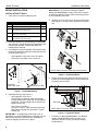
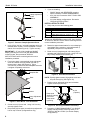
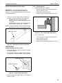
Figure 7: Remove Clamp Adjustment Screw
IMPORTANT ! : IF you will be installing a SINGLE
display with RECESSED mounting holes, then proceed
to "DISPLAY INSTALLATION" before continuing with this
mount installation procedure.
3. Using 2.5mm hex key, re-install baseplate with three
retained attach screws. Ensure baseplate nut faces
interior of mount (See Figure 6). Tighten securely.
2. Determine approximate location for mount keeping in
mind display size, extension, height adjustment (if
applicable), and pitch/roll requirements.
IMPORTANT ! : IF you will be installing a SINGLE
display (including KCY-210/-220) with RECESSED
mounting holes, then proceed to "DISPLAY
INSTALLATION" before continuing with this mount
installation procedure.
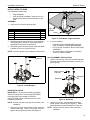
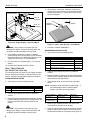
3. Place mount (10) against pole, with clamp (20) on
opposite side of pole (See Figure 9). Using 5/32" hex
key, loosely assemble with screws (30).
Pole
10
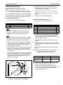
4. From below desk, insert retained clamp adjustment
screw and washer through bracket (20) and up
through hole in desk (See Figure 8). Using
3/16" hex key, thread screw into baseplate nut but do
not tighten completely at this time.
30
(3 places)
20
Baseplate Nut
Figure 9: Pole Mount Installation
Desk
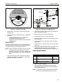
NOTE: Equally tighten screws (30) against mount and
the pole clamp (20). (See Figure 10)
4. Position mount at desired height and orientation.
Tighten screws (30) securely.
20
20
Washer
Clamp Adjustment
Screw
Figure 8: Desk Mount - Hole Installation
5. Center mount (10) over hole. Using 3/16" hex key,
securely tighten screw.
6. Drop screw (30) into open (unused) clamp adjustment
hole on top of mount (for appearance only).
6
Keep equal
distance between
mount and
clamp when
tightening
30
(3 places)
Figure 10: Securing Pole Mount and Clamp
5. Proceed to "CABLE MANAGEMENT" (for SINGLE
display with RECESSED mounting holes), or to
"DISPLAY INSTALLATION" (for all other display
configurations).