1
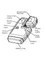
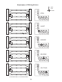
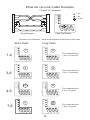
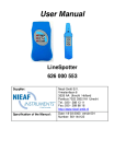
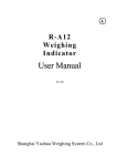
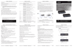
LanRoamerf Tester/Analyzer
www.jdsu.com/hbn
User's Guide
Detachable
Remote
Green Pair
Lights
Shield
Light
Tone
Light
Amber
Pair
Lights
Tone
Button
Fault
Lights
Battery
Low
Battery Cap
Warning!
Do not attach to energized cables. The
LanRoamer™ may be damaged.
Caution!
Improperly crimped or un-crimped plugs can
damage the jacks on the LanRoamer™. Inspect
plugs for proper termination and crimping
before inserting into the tester. Contacts should
always be recessed into the plastic grooves of
the plug.
Introduction
The LanRoamer™ cable tester is a unique
blend of a popular type of low-end tester
interface with an advanced microprocessor
controller. The most popular aspects of this
type of tester are an indication at both ends
that the cable has been tested, no buttons to
push to perform a test and a case that snaps
together for storage. The microprocessor brings
the additional features of automatic power
management, split pair error detection, direct
indication of the type and location of faults
and tone generation. The patented split pair
detection technique allows the LanRoamer™ to
have these advanced features at a reasonable
price.
Features
•
uto-on and auto-off when testing cables,
A
just plug both ends into tester!
•
able test results displayed on main unit
C
and remote unit, in less than 2 seconds
after plugging in the cable
•
Snap-together case for easy storage and
convenient patch cable testing
•
Tone generator mode for use with tone
tracers, auto-off
•
Debug mode with from/to and failures for
each pair
•
Battery low indicator
•
Tests for shorts, opens, miswires,
reversals and split pairs
Description
The main unit has four green pair lights, a
green shield light, four red fault lights, a red
battery low light and a green tone light. The
remote unit has four amber pair lights. When
a connection from the main unit to the remote
is sensed, testing begins automatically. On
the main unit, the lights for each pair will
either be ON, OFF or FLASHING. An ON light
indicates a good pair, an OFF light indicates
an open pair and a FLASHING light indicates
a bad pair. If a pair is bad, one or more of
the fault lights will be flashing to indicate the
type or types of faults. On the remote unit,
the pair lights are either ON or OFF. An ON
light indicates a good pair, and an OFF light
indicates an open or bad pair. Holding down
the tone button until all lights momentarily
turn on starts the debug mode. The pairs
are stepped through one at a time to display
connection and fault information on a pair-bypair basis. A second press of the tone button
turns off debug or completion of two complete
cycles. When not in debug mode, pressing
and releasing the tone button in less than 1.5
seconds causes the LanRoamer™ to generate
a warble tone signal on all pairs, flashing the
tone light to indicate tone is on. The tone will
turn off automatically after three hours, or with
a second press of the tone button.
Instructions for Use
LanRoamer™ powers off automatically after
5 minutes of continuously testing a cable.
Disconnecting the cable restores normal
function. Be sure to install a battery if using for
the first time—see battery installation.
To Test a Patch Cable
1) Plug one end of patch cable into main unit.
2) Plug other end of cable into remote unit.
3) The tester will power on immediately,
indicating a test in progress by quickly
winking the pair lights on both the main
and remote; it will then be followed by a
combination of pair lights on — this shows
the test results. See Main Unit Results and
Remote Unit Results sections on page 7.
4) D
isconnect patch cable after test. The test
repeats automatically every 2.3 seconds if
the cable has only open and passing pairs
and repeats every 4 seconds if there are
failures.
To Test Installed Cable (Office jack to patch
panel)
1) R
emove remote unit from main unit by
sliding remote towards top of the main unit.
2) Attach one end of supplied one foot jumper
cable to remote and other end to wall jack.
3) Attach one end of the second supplied onefoot jumper to main unit and the other end to
the patch panel jack.
4) The tester will power on immediately,
indicating a test in progress by quickly
winking the pair lights on both the main and
remote; it will be immediately followed by a
combination of pair lights on — this shows
the test results. See Main Unit Results and
Remote Unit Results sections on page 7.
5) D
isconnect after test. The test repeats
automatically every 2.3 seconds if the
cable has only open and passing pairs and
repeats every 4 seconds if there are failures.
Application Hints: The jumper cables must be
short compared to the cable run for accurate
split pair indication, no more than 10% of the
total run length.
To Test Coax (Requires optional RJ45-to-coax
adapter)
1) P
lug the RJ45 to F coax adapters into the
remote and
main units.
2) Attach cable to be tested to f connectors.
3) The tester will power on if it senses the
cable. If not, the cable is open. The coax
adapter is connected to the 1-2 pair and will
be on steady if good, or blink the 1-2 and
short lights if shorted.
To Place Tone on a Cable
1) P
ress and release the TONE button. The
light immediately above the button will start
flashing.
2) C
onnect cable to be traced to main unit.
For best signal, do not connect remote. Due
to the shielding effect of twisted pairs, the
strongest signal is obtained by connecting
only one wire in a cable to the tone source.
3) To turn tone off, press the TONE button
a second time. The tone will turn off
automatically after 3 hours.
Interpreting Results
Definition of Errors – (See “Examples
of Wiring Errors”) The four fault lights are
discussed below in order of severity. The
severity has to do with the ability of the type
of error to mask lower severity errors. For
example, if there is a short in the cable,
miswires, reversals and split pairs cannot be
detected for the pairs involved in the short
fault. Multiple faults on multiple pairs can be
better understood by using the debug mode to
examine the errors one pair at a time.
Short – The pair has a low resistance
connection from one wire of the pair to the
other wire of the pair or to any other wire in the
cable or the shield. A single flashing pair light
and the short light indicate a short within the
pair. Multiple flashing pair lights and only the
short light indicate shorts between the pairs
involved.
Miswire – A wire or both wires of a pair are not
connected to the correct pins at the other end
of the cable. Debugs “from–to” format is very
helpful in visualizing what the specific miswire
is.
Reverse – A reverse is a special case of a
miswire in which the pair is wired to the correct
pair of pins or to another designated pair of
pins, but the two leads are reversed.
Split Pair – A split pair is an error in the twisting
of the wires together within the cable. The
cables generally are made up of eight wires
twisted together in 4 pairs. These 4 pairs are
designated as pairs by the wiring standards
and are intended to carry a signal and it’s
return. 1 & 2, 3 & 6, 4 & 5 and 7 & 8 are the
pairs designated by T568A/B. A cable can
be wired with correct continuity, but not with
correct pairing. This most often happens when
the cable is terminated consistently at both
ends, but in the wrong order. A dynamic or AC
test is required to detect this type of error. If
the only error is a split pair error, the cable has
correct continuity. If cross talk is not a concern,
as in flat satin cable, the cable is good if the
only error is the split pair error.
Examples of Wiring Errors
RSE
PAIR
REVE
SPLT
RSE
PAIR
REVE
SPLT
1-2
3-6
MISWIRE
4-5
7-8
RSE
E
PAIR
REVE
SPLT
RT
WIR
SHO
MIS
1-2
3-6
REVERSE
4-5
7-8
RSE
PAIR
REVE
SPLT
IRE
RT
SHO
W
MIS
1-2
3-6
SPLIT PAIR
4-5
7-8
PAIR
RSE
REVE
SPLT
RT
E
WIR
SHO
(1 not twisted with 2; 3 not twisted with 6)
MIS
1
2
3
4
5
6
7
8
7-8
E
1
2
3
4
5
6
7
8
SHORT
4-5
RT
1
2
3
4
5
6
7
8
3-6
WIR
1
2
3
4
5
6
7
8
1-2
SHO
1
2
3
4
5
6
7
8
7-8
MIS
1
2
3
4
5
6
7
8
OPEN
4-5
RT
1
2
3
4
5
6
7
8
= ON
= FLASH
3-6
E
WIR
1
2
3
4
5
6
7
8
= OFF
1-2
SHO
1
2
3
4
5
6
7
8
MIS
1
2
3
4
5
6
7
8
Main Unit Results – The main unit indicates
the beginning of a test by flashing the pair
lights in sequence top to bottom. The cable
is then tested and the results displayed as
follows:
Pair light off – Pair is open. Depending on the
wiring standard, this may be correct.
Pair light on – Pair is wired correctly.
Pair light is flashing – One or more errors were
detected for this pair, as indicated by flashing
error lights.
If there are no flashing lights, the results are
displayed for 2 seconds. If there was an error,
the results are displayed for twice as long.
Remote Unit Results – The remote unit
indicates the beginning of a test by flashing the
pair lights quickly, the order or number of lights
flashed depends on the cable being tested.
The cable is then tested and the results
displayed as follows:
Pair light off – Pair is open or has a fault.
Depending on the wiring standard, this may be
correct.
Pair light on – Pair is wired correctly.
If there are no errors, the results are displayed
for 2 seconds.
10
If there was an error, the results are displayed
for twice as long.
If the lights for the pairs expected are on, the
cable is good.
Debug Mode – (See “Ethernet Up-Link Cable
Example”) The debug mode is provided to allow
diagnosis of faults, especially when there are
multiple errors on multiple pairs. To enter the
debug mode, press and hold the tone button
until all lights on the main unit light (lamp test).
Once the lamp test is complete, debug displays
the results of the last cable test. This is from
internal memory, so the cable is not required to
be connected when running debug.
The debug display begins with a short flash on
the 1-2 pair to indicate that what follows is the
result for the 1-2 pair test (or the “from”). If the
pair was not open, a second longer flash on
one or more pair lights designates what pair 12 is connected “to” at the remote end, or pairs
involved in a fault condition along with the fault
lights. The 3-6, 4-5 and 7-8 pair lights each in
turn begin with a short flash followed by the
results for that pair. The individual pair results
continue to be displayed until the tone button
is pressed again or two complete cycles of all
pairs is completed. The remote unit does not
display anything when in debug mode.
11
Ethernet Up-Link Cable Example
1-2 and 3-6 swapped
1
2
3
4
5
6
7
8
= OFF
1-2
= ON
3-6
= FLASH
4-5
7-8
SPLT
RSE
PAIR
E
WIR
MIS
Wiring Diagram
REVE
RT
SHO
1
2
3
4
5
6
7
8
Cable Test Results
Sequence of LanRoamer™ debug mode displays for Ethernet up-link cable
Short Flash
Long Flash
1-2
1-2
1
3-6
4-5
SPLT
RSE
PAIR
IRE
T
SHOR
4
3-6
4-5
7-8
Pair connected from
3-6 to 1-2 (miswire)
7-8
SPLT
RSE
PAIR
IRE
T
SHOR
MISW
REVE
PAIR
RSE
REVE
SPLT
IRE
T
SHOR
MISW
1-2
1-2
5
3-6
4-5
6
3-6
4-5
7-8
7-8
Pair connected from
4-5 to 4-5 (good)
IR
PA
SPLT
IRE
T
SHOR
MISW
RSE
REVE
IR
E
RS
REVE
PA
SPLT
IRE
T
SHOR
MISW
1-2
1-2
7
3-6
7-8
MISW
4-5
REVE
PAIR
RSE
REVE
IRE
T
SHOR
MISW
1-2
3
3-6
4-5
Pair connected from
1-2 to 3-6 (miswire)
7-8
1-2
3-6
4-5
SPLT
1-2
2
3-6
7-8
4-5
8
3-6
4-5
7-8
Pair connected from
7-8 to 7-8 (good)
7-8
SPLT
PAIR
T
SHOR
IRE
MISW
RSE
REVE
PAIR
IRE
RSE
REVE
SPLT
T
SHOR
MISW
12
Battery Replacement
When the battery low light is on while
generating tone or testing cables, the battery
should be replaced as soon as practical. The
cable testing results will become unreliable
when the battery reaches about 4.5 volts.
To replace battery:
1) R
emove rubber battery cap by peeling back
a corner until it pops off.
2) P
ull battery out of cavity and remove battery
snap.
3) C
onnect a new Alkaline 9 volt battery to
battery snaps.
4) S
lide battery into cavity and snap cap in
place.
13
Specifications
Electrical
Battery Life, typical alkaline — times are for the
full capacity of the battery used continuously in
one of the following modes —Standby: 2.5 years
Cable Testing: 20 hours
Tone Mode: 170 hours
Cable Types: S
hielded or unshielded, CAT3,
CAT4, CAT5, CAT5e, CAT6
Minimum cable length for testing split pairs:
1 meter (3 feet)
Maximum cable length for testing:
305 meters (1000 feet)
Coax Cable: 100 ohms maximum DC resistance,
center conductor plus shield
Environmental
Temperature
Operating:0 to 50°C(32 to 122°F)
Storage:-20 to 70°C( -4 to 158°F)
Humidity: 10% to 90%, non-condensing
Physical
Length:14.5 cm (5.70 in)
Width: 7.2 cm (2.85 in)
Height:3.0 cm (1.20 in)
Weight (with battery): 162 gm (5.7 oz.)
(Specifications subject to change)
14
Warranty
JDSU guarantees that its products will be free
of all defects in material and workmanship.
This warranty extends for the period of 12
months for test instruments and 3 months for
cables from date of manufacture or purchase
(proof of purchase required).
All product deemed defective under this
warranty will be repaired or replaced at JDSU’s
discretion. No further warranties either implied
or expressed will apply, nor will responsibility
for operation of this device be assumed by
JDSU.
WEEE Directive Compliance: JDSU has
established processes in compliance with the
Waste Electrical and Electronic Equipment
(WEEE) Directive, 2002/96/EC. This product
should not be disposed of as unsorted
municipal waste and should be collected
separately and disposed of according to your
national regulations. In the European Union,
all equipment purchased from JDSU after
2005-08-13 can be returned for disposal at the
end of its useful life. JDSU will ensure that all
waste equipment returned is reused, recycled,
or disposed of in an environmentally friendly
manner, and in compliance with all applicable
national and international waste legislation. It
15
is the responsibility of the equipment owner to
return the equipment to JDSU for appropriate
disposal. If the equipment was imported by a
reseller whose name or logo is marked on the
equipment, then the owner should return the
equipment directly to the reseller. Instructions
for returning waste equipment to JDSU can
be found in the Environmental section of
JDSU’s web site at www.jdsu.com. If you
have questions concerning disposal of your
equipment, contact JDSU’s WEEE Program
Management team at [email protected].
16
Shipping
Before returning any product to JDSU, you
must first request a Return Merchandise
Authorization Number by contacting our
Customer Service Dept. at (805) 383-1500.
1) No shipments will be accepted without this
number, which must be clearly marked on
the shipping label.
2) Ship the equipment with a copy of the sales
receipt, if available.
3) Attach a description of the operational
problem.
4) Include a contact name, phone number and
E-mail address.
5) Pack securely to prevent damage during
shipping.
6) Ship prepaid to: JDSU, 808 Calle Plano,
Camarillo, CA 93012
Support Service
For technical information and support, please
visit www.jdsu.com/hbn.
17
Notes:
18
Notes:
19
Contact Information:
808 Calle Plano
Camarillo, CA 93012
USA
Regional Sales
North America
Tel: +1 805 383 1500
Fax:+1 805 383 1595
Latin America
Tel: +55 11 5503 3800
Fax:+55 11 5505 1598
Asia Pacific
Tel: +852 2892 0990
Fax:+852 2892 0770
EMEA
Tel: +49 7121 86 2222
Fax:+49 7121 86 1222
Customer Service
www.jdsu.com/customerservice
TU9840 (Rev B - 04/07)