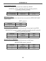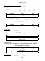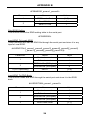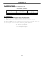
1
® 8x8 DVI Matrix EXT-DVI-848 User Manual www.gefen.com f ASKING FOR ASSISTANCE Technical Support: Telephone Fax (818) 772-9100 (800) 545-6900 (818) 772-9120 Technical Support Hours: 8:00 AM to 5:00 PM Monday thru Friday Pacific Time Write To: Gefen, LLC c/o Customer Service 20600 Nordhoff St Chatsworth, CA 91311 www.gefen.com [email protected] Notice Gefen, LLC reserves the right to make changes in the hardware, packaging and any accompanying documentation without prior written notice. 8x8 DVI Matrix is a trademark of Gefen, LLC © 2010 Gefen, LLC, All Rights Reserved All trademarks are the property of their respective owners. Rev A7 CONTENTS 1 Introduction 2 Operation Notes 3 Features 4 8x8 DVI Matrix Front Panel Layout 5 8x8 DVI Matrix Front Panel Descriptions 6 8x8 DVI Matrix Back Panel Layout 7 8x8 DVI Matrix Back Panel Descriptions 8 EXT-RMT-Matrix-848 Panel Layout 9 EXT-RMT-Matrix-848 Panel Descriptions 10 Connecting And Operating The 8x8 DVI Matrix 11 8x8 DVI Matrix Remote Description & Operation 12 RMT-848IR IR Channel Configuration 13 EXT-RMT-Matrix-848 Remote Operation 14 RMT-8-IR IR Channel Configuration 15 RS-232 Serial Control Interface 16 Network Cable Wiring Diagram 17 Appendix A 19 Appendix B 24 Specifications 25 Warranty INTRODUCTION Congratulations on your purchase of the 8x8 DVI Matrix. Your complete satisfaction is very important to us. Gefen Gefen delivers innovative, progressive computer and electronics add-on solutions that harness integration, extension, distribution and conversion technologies. Gefen’s reliable, plug-and-play products supplement cross-platform computer systems, professional audio/video environments and HDTV systems of all sizes with hard-working solutions that are easy to implement and simple to operate. The Gefen 8x8 DVI Matrix Now you can easily combine eight cross-platform computers and eight digital displays without networking. Our 8x8 DVI Matrix provides a simple, reliable and highly effective method of creating multiple computer workstations, with each workstation capable of accessing any one of the computers or sources at any time by remote control. You also have the option of setting up the eight stations locally or extending them with a Gefen extender. How It Works The 8x8 Matrix has eight DVI inputs and eight DVI outputs. You simply connect your eight computer DVI ports to the 8x8 Matrix inputs, then connect your eight DVI displays to the 8x8 Matrix outputs. 1 OPERATION NOTES READ THESE NOTES BEFORE INSTALLING OR OPERATING THE 8X8 DVI MATRIX • The 8x8 DVI Matrix is HDCP compliant when used in EDID pass-through mode (when a single DVI input is mapped to a single DVI output). Additional Matrix outputs which attempt to route video signals to a source device that has already made an HDCP connection with an HDCP-compliant display will not be able to display an image. • By default, EDID routing is based on the first connected source and display. For example, if monitor A is the first display to connect to source 1 its EDID will be used. All other displays that connect to source 1 thereafter will have its EDID ignored. If display 1 switches to another source a hot-plug signal will be sent and the EDID from the next display that is connected, in numerical order, will be used. • The Status Output display will only list the current display/source routing. • There is no internal scaling in the 8x8 DVI Matrix. All of the attached monitors must be able to display the resolutions output by the source devices. For maximum compatibility it is recommended that only one compatible/common resolution be used by all of the source devices. 2 FEATURES Features • Increases your productivity by providing you with access to eight computers from eight workstations • Maintains beautiful, sharp HDTV resolutions up to 1080p, 2K, and 1920x1200 • Discrete IR remote control included • Long-distance remote control at distances of up to 330 feet using optional wired CAT5 cabled remotes • Serial RS232 port for remote control via computer or a control automation device such as Crestron • Supports DDWG standards for DVI monitors. Package Includes (1) 8x8 DVI Matrix (1) RMT-848IR IR Remote Control (1) 24V DC Power Supply (8) 6-foot DVI cables (1) Rack Ears (1) User’s Manual 3 1 2 3 8X8 DVI MATRIX FRONT PANEL LAYOUT 4 8X8 DVI MATRIX FRONT PANEL DESCRIPTIONS 1 LED Status Display This display will list the current display/source routes. Monitor (A~H) Selected Source (1~8) Monitor Output’s are labeled 1 through 8 on the rear panel of the 8x8 DVI Matrix. These numbers correspond to the letters A through H on the LED Status Display. The top row of letters will remain static while each input number below will represent which source each of the displays are currently viewing. HPD (Hot Plug Detect) Whenever a display is connected/disconnected an HPD event will occur. This will be displayed on the LED Status Display. A 2 stage status update will occur whenever a HPD event occurs 1. 2. The first stage will return the HPD status for all outputs. H means that the HPD status is HIGH and an L indicates that the HPD status is LOW. In the example above, all outputs except for A has an HPD that is LOW, while output A has an HPD that is HIGH. The second stage will return the active monitor status for all outputs. M means that a monitor has been detected and an S indicates that no monitor is attached or is active. In the example above, all outputs except for A are not detecting a monitor, while output A detects a monitor on its output. 3 IR Receiver Use the included RMT-848IR remote control to route video to the different displays. 4 Power LED Indicator This input indicator will become active once the included 24V DC power adapter has been properly connected. 5 18 10 1 19 2 11 20 3 12 21 4 13 22 5 14 6 23 15 7 24 16 8 25 27 17 26 9 8X8 DVI MATRIX BACK PANEL LAYOUT 6 8X8 DVI MATRIX BACK PANEL DESCRIPTIONS 1-8 Optional Remote Switching Ports Ports 1 through 8 are used for remote switching using the optional component EXT-RMT-MATRIX-848. 9 RS-232 Serial Control Interface This port is used for serial communication for multiple functions. Access to certain features are only through the RS-232 interface. 10-17 DVI Input Ports Connect up to 8 DVI sources to DVI Input Ports 1 through 8. 18-25 DVI Output Ports Connect up to 8 DVI displays to DVI Output Ports 1 through 8. These output ports correspond to Monitors A through H on the LED Status Display. 26 24V DC Power Input Connect the included 24V DC power supply to this input. 27 IR Extender mini-jack input Connect the optional separately-sold Gefen IR Extender (shown below) to this input to conceal the Matrix and expose only the IR sensor, extend the range of the IR remote, or simply beautify installations by creating a sleek, custom appearance to the A/V setup. Gefen’s IR Extender, part # EXT-RMT-EXTIR 7 EXT-RMT-MATRIX-848 PANEL LAYOUT Front Panel 1 2 3 Back Panel 4 (PRODUCT SOLD SEPARATELY) 8 5 6 EXT-RMT-MATRIX-848 PANEL DESCRIPTIONS 1 Direct Select Buttons When this unit is attached to a CAT-5 port that corresponds to a display on the 8x8 DVI Matrix, use buttons 1 through 8 to select what source that display will be viewing. Buttons 1 through 8 directly correspond to DVI source inputs 1 through 8 on the 8x8 DVI Matrix. 2 IR Receiver This port will receive commands from the RMT-8-IR remote control (included with the EXT-RMT-MATRIX-848) for remote controlled switching at the extended location. 3 Active Input LED Indicator 1 through 8 LED indicators that will visually acknowledge which source is currently selected. 4 CAT-5 Input Port Connect a CAT-5 cable between this port and the CAT-5 remote switching ports (Item 1 through 8 on page 6) for remote switching. 5 IR EXTension Eye Connect the optional IR Receiver Extender (part# EXT-RMT-EXTIR) to this port. 6 RS-232 Serial Control Port This port can be used to control switching via RS-232 serial communication. 9 CONNECTING AND OPERATING THE 8X8 DVI MATRIX How to Connect the 8x8 DVI Matrix 1. Connect up to 8 DVI sources to the DVI Input ports on the 8x8 DVI Matrix using the supplied DVI cables. 2. Connect up to 8 DVI displays to the DVI Output ports on the 8x8 DVI Matrix using user supplied DVI cables. 3. Optionally connect up to 8 remote switching units (Part# EXT-RMT-MATRIX848) to the RJ-45 Input ports on the rear panel on the 8x8 DVI Matrix using user supplied CAT-5, CAT-5e or CAT-6. NOTE: Maximum extension of the EXT-RMT-MATRIX-848 units are 330 Feet (100 Meters). Operating the 8x8 DVI Matrix There are 2 main ways to control the 8x8 DVI Matrix. Local and remote control. Local control is done using the included RMT-848IR remote control. Remote control is done using the optional EXT-RMT-MATRIX-848 switching units. Local Control To control the unit locally, please use the included RMT-848IR remote control. Please see page 12 for usage information. Remote control To control the unit remotely, please use the EXT-RMT-MATRIX-848 remote switcher. Each remote switcher has 8 direct select push-buttons that correspond to DVI inputs 1 through 8. Press the push-button corresponding to the desired source for viewing. There is also the option to use RS-232 switching via the RS232 port located on the rear panel of the EXT-RMT-MATRIX-848. 10 8X8 DVI MATRIX REMOTE DESCRIPTION & OPERATION How to Route Sources to Displays Input Sources and Displays connect to the Matrix on the rear panel. Sources use input connectors 1 thru 8 while Displays use connectors A thru H. Please see page 6 for the Matrix Back Panel Layout diagram for details. Routing a Source to a Display is done with the RMT-848IR Remote Control unit, shown immediately below. Number Keys (Sources) Letter Keys (Displays) Routing is done in two simple steps. There is one button-press for each step. For example, here is how to route Source 4 to Display C: 1. Press the “C” letter key on the Remote once to select Output/Display “C”. 2. Press the “4” number key once to select Input Source 4. Source 4 will now be routed to Display C and a crisp, vibrant picture of the Source 4 will now appear on Display C. The LCD Display will show the route created (circled below): Repeat these steps to route any video source to any display. 11 RMT-848IR IR CHANNEL CONFIGURATION The RMT-848IR remote control has 4 discrete channels for use if the default IR code set conflicts with other remote control commands in your setup. There are 2 DIP Switches underneath the battery on the RMT-848IR remote control. These DIP Switches must match the IR channel in use on the 8x8 DVI Matrix. The underside of the 8x8 DVI has multiple banks of DIP Switches. Please see the diagram of the 8x8 DVI Matrix below for the correct bank and DIP Switches that are used for IR channel configuration. Information on the remaining DIP Switch banks can be found in Appendix A. See below for DIP Switch configurations for each of the available remote channels. 8x8 DVI Matrix DIP Switches RMT-848IR DIP Switches IR CHANNEL CONFIGURATION RMT-848IR REMOTE CONTROL Remote Channel 1: Default 8x8 DVI Matrix Remote Channel 1: Default Remote Channel 2: 1 1 2 Remote Channel 3: 2 1 2 2 Remote Channel 3: Remote Channel 4: 1 Remote Channel 2: 1 12 2 1 2 Remote Channel 4: 1 2 1 2 EXT-RMT-MATRIX-848 REMOTE OPERATION (PRODUCT SOLD SEPARATELY) Once the EXT-RMT-MATRIX-848 Remote is installed and connected to a remote output port on the 8x8 DVI Matrix, use the direct selection buttons to chose a source to view. Once a source is chosen, its corresponding LED should become active. Optionally, switching can be done using the RMT-8-IR remote control included with the optional EXT-RMT-MATRIX-848 or through the RS-232 serial communications port on the rear panel. LED Indicator Input Selection Buttons (REMOTE SOLD SEPARATELY) The RMT-8-IR remote control can be used to select the source that will be displayed on the monitor connected to the EXT-RMT-MATRIX-848. RMT-8-IR Button DVI Source 1 1 2 2 3 3 4 4 5 5 6 6 7 7 8 8 13 RMT-8-IR IR CHANNEL CONFIGURATION The RMT-8-IR remote control (included with purchase of the EXT-RMT-MATRIX-848) has 4 discrete IR channels for use if the default IR code set conflicts with other remote control commands in your setup. There are 2 DIP Switches underneath the battery compartment cover on the RMT-8-IR remote control that must match DIP Switches on the EXT-RMT-MATRIX-848. There are 4 DIP Switches located on the underside of the EXT-RMT-MATRIX-848. DIP Switches 1 and 2 on the EXT-RMTMATRIX-848 correspond to DIP Switches 1 and 2 on the RMT-8-IR remote control. See below for DIP Switch configuration of each of the available remote channels. RMT-8-IR DIP Switches RMT-8-IR REMOTE CONTROL Remote Channel 1: Default Remote Channel 2: 1 2 Remote Channel 3: 1 2 1 2 Remote Channel 4: 1 2 EXT-RMT-MATRIX-848 Remote Channel 1: Default Remote Channel 2: 1 2 3 4 1 2 3 4 Remote Channel 3: Remote Channel 4: 1 2 3 4 1 2 3 4 14 RS-232 SERIAL CONTROL INTERFACE 54321 12345 9876 6789 Only Pins 2 (RX), 3 (TX), and 5 (Ground) are used on the RS-232 serial interface RS232 Settings Bits per second ................................................................................................. 19200 Data bits .................................................................................................................... 8 Parity .................................................................................................................. None Stop bits .....................................................................................................................1 Flow Control ....................................................................................................... None Please see Appendix B for information on the available RS-232 commands. 15 NETWORK CABLE WIRING DIAGRAM Gefen has specifically engineered their products to work with the TIA/EIA-568-B specification. Please adhere to the table below when field terminating cable for use with Gefen products. Failure to do so may produce unexpected results and reduced performance. Pin Color 1 Orange / White 2 Orange 3 Green / White 4 Blue 5 Blue / White 6 Green 7 Brown / White 8 Brown 12345678 CAT-5, CAT-5e, and CAT-6 cabling comes in stranded and solid core types. Gefen recommends using solid core cabling. CAT-6 cable is also recommended for best results. Each cable run must be one continuous run from one end to the other. No splices or use of punch down blocks. 16 APPENDIX A The 8X8 DVI Matrix has 4 banks of DIP Switches located on the underside of the main unit. This section will outline the function of each DIP Switch bank. DIP SWITCH BANKS Front Panel Bank A Bank B Bank C Bank D Rear Panel DIP Switch Bank Description A RMT-848IR channel configuration B Monitor Pre-Emphasis C EDID Pass Through D Individual +5V Enable for Fiber Optic extenders DIP SWITCH BANK A DIP Switch Description 1 RMT-848IR remote control channel configuration. This setting must match DIP Switch 1 on the RMT-848IR remote control. 2 RMT-848IR remote control channel configuration. This setting must match DIP Switch 2 on the RMT-848IR remote control. 3 NOT USED 4 NOT USED 5 NOT USED 6 NOT USED 7 NOT USED 8 General +5V enable on all outputs for use with fiber optic products that require 5V for operation. [OFF] Feature disabled [ON] +5V DC enabled. 17 APPENDIX A DIP SWITCH BANK B DIP Switch Monitor Description 1 A [OFF] 0 db pre-emphasis, [ON] 6 db pre-emphasis 2 B [OFF] 0 db pre-emphasis, [ON] 6 db pre-emphasis 3 C [OFF] 0 db pre-emphasis, [ON] 6 db pre-emphasis 4 D [OFF] 0 db pre-emphasis, [ON] 6 db pre-emphasis 5 E [OFF] 0 db pre-emphasis, [ON] 6 db pre-emphasis 6 F [OFF] 0 db pre-emphasis, [ON] 6 db pre-emphasis 7 G [OFF] 0 db pre-emphasis, [ON] 6 db pre-emphasis 8 H [OFF] 0 db pre-emphasis, [ON] 6 db pre-emphasis DIP SWITCH BANK C DIP Switch Input Description 1 1 [OFF] EDID pass-through [ON] EDID set to LOCAL 2 2 [OFF] EDID pass-through [ON] EDID set to LOCAL 3 3 [OFF] EDID pass-through [ON] EDID set to LOCAL 4 4 [OFF] EDID pass-through [ON] EDID set to LOCAL 5 5 [OFF] EDID pass-through [ON] EDID set to LOCAL 6 6 [OFF] EDID pass-through [ON] EDID set to LOCAL 7 7 [OFF] EDID pass-through [ON] EDID set to LOCAL 8 8 [OFF] EDID pass-through [ON] EDID set to LOCAL DIP SWITCH BANK D DIP Switch Input Description 1 1 [OFF] +5V disabled [ON] +5V enabled 2 2 [OFF] +5V disabled [ON] +5V enabled 3 3 [OFF] +5V disabled [ON] +5V enabled 4 4 [OFF] +5V disabled [ON] +5V enabled 5 5 [OFF] +5V disabled [ON] +5V enabled 6 6 [OFF] +5V disabled [ON] +5V enabled 7 7 [OFF] +5V disabled [ON] +5V enabled 8 8 [OFF] +5V disabled [ON] +5V enabled 18 EDID MANAGEMENT QUICK START GUIDE To use EDID Management functions, the EDID mode must be changed from Pass-Through to LOCAL. Please follow the steps below to set this mode. NOTE: LOCAL EDID mode does not support HDCP. 1. Locate Bank C on the underside of the 8x8 DVI Matrix. 2. Each input has a DIP switch associated with it. Select the inputs that will be changed to LOCAL mode and flip their DIP switch to the ON position. By default, all DIP switches are in the Pass-Through mode (OFF). Once the selected inputs are in LOCAL mode an EDID can then be set for each input. Follow the commands below to quickly load an EDID into the LOCAL bank of each input. These instructions use the Windows application Hyperterminal. For details on these and other RS-232 commands please see appendix B. 1. Connect a computer to the 8x8 DVI Matrix’s RS-232 port. 2. Use the RS-232 settings on page 15 to open a connection with the 8x8 DVI Matrix from the computer using the Hyperterminal application. 3. To store an EDID of a connected display into a LOCAL storage location, type in the following command: #EDIDDSTOLO A 1 This example will store the EDID from the monitor connected to output A to input 1. Simply modify the monitor and input characters to route any monitor’s EDID to any input’s LOCAL storage. This command supports multiple LOCAL storage parameters. For example, to store the EDID from the monitor connected to the output A to the LOCAL storage locations for all inputs (1 through 8), type the following command: #EDIDDSTOLO A 1 2 3 4 5 6 7 8 4. To check the EDID of a connected monitor, type the following command: #PRDSEDID A 1 This example will check the EDID from the monitor connected to output A. Simply modify the monitor character (A-H) to check a different output monitor’s EDID. 5. To check the EDID stored in any input’s LOCAL storage, type the following command: #PRLOEDID 1 1 This example will check the EDID that is stored in the LOCAL storage bank for input 1. Simply modify the input character (1-8) to check a different input’s stored LOCAL EDID. 19 APPENDIX B The 8X8 DVI Matrix uses RS-232 serial communication for access to a number of features. Please us this section for EDID storing, calling, and routing functions. REMOTE FUNCTION The remote functions are used to modify the setting of the product, such as: Input to output routing, EDID memory management etc. These functions are available only via serial communications on the RS-232 port. HELP FUNCTION To reference the commands listed in the following pages, simply type HELP and then enter key to display a list of the available commands. EDID STORAGE LOCATIONS There are 2 storage locations for EDIDs. The main storage location is located right in front of each input. These eight locations will transmit an EDID directly to the source devices connected to each input. These eight locations will be referred to as LOCAL in the following section. The second storage location is an EDID storage bank that can support up to seven EDIDs. Any EDID in this bank can then be uploaded to some or all of the LOCAL EDID storage locations for use by the source devices. This storage location will be referred to as the EDID BANK in the following section. Modify By Shortcut Switching Command First character indicates the output monitor. Second character indicates the input number. Example: ‘A5’ routes input 5 to output monitor A Matrix Status Command The ‘M’ or ‘m’ command will return the current routing state. Shortcut Routing Command This command sets the matrix routing state according to a preset routing state. First character is ‘S’ or ‘s’, second character indicates the state that is set by function #PSASRS or #MSASRS (please see page 24) Setting Function Menu The ‘P’ or ‘p’ command will return the settings function menu. Modify By Function The syntax for each function is always the same. The ‘#” character is the start flag followed by the function name in capital letter and a space. The space tells the MCU that the function name is ending. Finally, the parameters required for each function are separated by a space and ending by the ‘\r’ character or “Enter” 20 APPENDIX B Example: #FunctionName_param1_param2_param3_param4…\r Set Preset Routing State This function enables the user to determine up to 10 routing states to save in memory. #PSASRS_param1_param2_param3_param4_param5_param6_param7_ param8_param9\r Parameter Name Value 1 Routing state [0:9] 2 Input route to MONITOR A [1:8] 3 Input route to MONITOR B [1:8] 4 Input route to MONITOR C [1:8] 5 Input route to MONITOR D [1:8] 6 Input route to MONITOR E [1:8] 7 Input route to MONITOR F [1:8] 8 Input route to MONITOR G [1:8] 9 Input route to MONITOR H [1:8] Set Current Matrix As Routing State #MSASRS_param1\r Parameter Name Value 1 Routing state [0:9] Print Routing State Table #PRRS\r Mask Outputs This function masks the output by by setting the DS HPD to low. #MASK_param1[_param2][_param3][_param4][_param5] [_param6][_param7][_param8]\r Parameter Name Value 1 (2-8 optionally) MONITOR [A : H] 21 APPENDIX B Unmask Masked Outputs This function unmasks outputs that were masked by “#MASK” #UNMASK_param1[_param2][_param3][_param4][_param5] [_param6][_param7][_param8]\r Parameter Name Value 1 (2-8 optionally) MONITOR [A : H] RMT-848IR Address This function set the remote channel that must match the GEFEN RMT-848IR remote control. #RMT_param1\r Parameter Value 1 [0:3] DS EDID Store In Locals Edid This function reads EDID file from DS and store it in any input Locals EDID. #EDIDDSTOLO_param1_param2[_param3][_param4][_param5] [_param6] [_param7][_param8][_param9]\r Parameter Name Value 1 MONITOR [A:H] 2 (3-9 optionally) INPUT [1:8] DS EDID Store In EDID Bank This function reads EDID file from DS and store it in EDID bank. #EDIDDSTOBA_param1_param2\r Parameter Name Value 1 MONITOR [A:H] 2 EDID bank offset [1:7] 22 APPENDIX B EDID From Bank Store In Locals EDID This function reads an EDID file from the EDID bank and stores it in any Input’s local EDID. #EDIDBATOLO_param1_param2[_param3][_param4][_param5][_param6] [_param7][_param8][_param9]\r Parameter Name Value 1 EDID bank offset [1:7] 2 (3-9 optionally) INPUT [1:8] Route Input DDC To Local EDID This function routes the Input DDC to the Local EDID. #DDCTOLO_param1\r Parameter Name Value 1 INPUT [1:8] Print DS EDID This function reads the DS EDID file and sends it to the serial port. #PRDSEDID_param1_param2\r Parameter Name Value 1 MONITOR [A:H] Send BIN file 0 Send TXT file 1 2 Print Local EDID This function reads the Input Local EDID file and sends it to the serial port. #PRLOEDID_param1_param2\r Parameter Name Value 1 INPUT [1:8] 2 Send BIN file 0 Send TXT file 1 Print EDID Bank This function reads the EDID file from the EDID bank and send it to the serial port. 23 APPENDIX B #PRBAEDID_param1_param2\r Parameter Name Value 1 EDID bank offset [1:7] Send BIN file 0 Send TXT file 1 2 Print EDID Setting This function sends the EDID setting table to the serial port. #PRSEEDID\r Load EDID To Locals EDID These functions will load an EDID file through the serial port and store it in any Input’s Local EDID. #LOEDIDTOLO_param1_param2_param3[_param4][_param5][_param6] [_param7][_param8][_param9][_param10]\r Parameter 1 2 3 (4-10 optionally) Name Value Semi echo mode 0 Full echo mode 1 EDID.bin file (256 bytes) 1 EDID.bin file (256 bytes) 2 INPUT [1:8] Load EDID To EDID Bank This function loads and EDID through the serial port and store it in the EDID bank. #LOEDIDTOBA_param1_param2\r Parameter 1 2 3 Name Value Semi echo mode 0 Full echo mode 1 EDID.bin file (256 bytes) 1 EDID.bin file (256 bytes) 2 EDID bank offset [1:7] 24 APPENDIX B Set Output Pre Emphasis This function will set output Pre Emphasis in db. #PE_param1_param2\r Parameter Name Value 1 MONITOR [A:H] 2 Pre Emp. level [db] [0,2,4,6] Set Default Setting This function will set the product back to its default setting. 1. 2. Routing state will be INPUT1-MONA, INPUT2-MONB, …, All the features with default to how the hardware switches are set. The DVI and HDMI 8x8 has the following shortcut routing commands. If the user has not changed these commands, the routing will be as follows: ‘s0’ - Route 1-A, 2-B, 3-C ... ‘sx’ - All outputs to input x 25 SPECIFICATIONS Video Amplifier Bandwidth ................................................... 165 MHz per channel Single Link Range .............................................. 1080p (HDTV) / 1920x1200 (PC) Input Video Signal .............................................................................. 1.2 Volts p-p Input DDC Signal ......................................................................... 5 Volts p-p (TTL) Remote Control Ports .................................. One RS232 female, One mini-stereo Rack mountable ............................................... 2U rack space, rack ears included DVI Connector ................................................... DVI-I 29 Pin Female (digital only) Power Supply ............................................................................................ 24V DC Power Consumption ....................................................................... 60 Watts (max) 26 WARRANTY Gefen warrants the equipment it manufactures to be free from defects in material and workmanship. If equipment fails because of such defects and Gefen is notified within two (2) years from the date of shipment, Gefen will, at its option, repair or replace the equipment, provided that the equipment has not been subjected to mechanical, electrical, or other abuse or modifications. Equipment that fails under conditions other than those covered will be repaired at the current price of parts and labor in effect at the time of repair. Such repairs are warranted for ninety (90) days from the day of reshipment to the Buyer. This warranty is in lieu of all other warranties expressed or implied, including without limitation, any implied warranty or merchantability or fitness for any particular purpose, all of which are expressly disclaimed. 1. Proof of sale may be required in order to claim warranty. 2. Customers outside the US are responsible for shipping charges to and from Gefen. 3. Copper cables are limited to a 30 day warranty and cables must be in their original condition. The information in this manual has been carefully checked and is believed to be accurate. However, Gefen assumes no responsibility for any inaccuracies that may be contained in this manual. In no event will Gefen be liable for direct, indirect, special, incidental, or consequential damages resulting from any defect or omission in this manual, even if advised of the possibility of such damages. The technical information contained herein regarding the features and specifications is subject to change without notice. For the latest warranty coverage information, please visit Gefen’s Warranty web page at http://www.gefen.com/kvm/aboutus/warranty.jsp PRODUCT REGISTRATION Please register your product online by visiting Gefen’s web site at http://www.gefen.com/kvm/Registry/Registration.jsp 27 *ma-DVI-848* Rev A7 20600 Nordhoff St., Chatsworth CA 91311 1-800-545-6900 818-772-9100 www.gefen.com fax: 818-772-9120 [email protected]