1
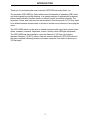
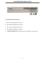
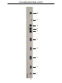
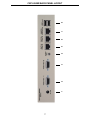
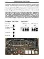
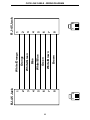
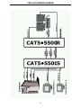
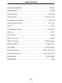
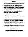
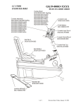
®
CAT5•5500
EXT-CAT5-5500
USER'S MANUAL
www.gefen.com
ASKING FOR ASSISTANCE
Technical Support:
Telephone
(818) 772-9100
(800) 545-6900
Fax
(818) 772-9120
Technical Support Hours:
8:00 AM to 5:00 PM Monday thru Friday.
Write To:
Gefen Inc.
c/o Customer Service
20600 Nordhoff St.
Chatsworth, CA 91311
[email protected]
www.gefen.com
Notice
Gefen Inc. reserves the right to make changes in the hardware, packaging and any
accompanying documentation without prior written notice.
CAT5•5500 is a trademark of Gefen Inc.
© 2010 Gefen Inc., All Rights Reserved
Rev B1
TABLE OF CONTENTS
1
Introduction
2
How It Works
3
CAT5•5500S Front Panel Layout
4
CAT5•5500R Front Panel Layout
5
CAT5•5500S Back Panel Layout
6
CAT5•5500 Back Panel Function Descriptions
7
CAT5•5500R Back Panel Layout
8
CAT5•5500R Back Panel Functions Descriptions
9
CAT5 Cable Length Setup
10
Link Cable Wiring Diagrams
11
CAT5•5500 - Wiring Diagram
12
System Specifications
13
Warranty
OPERATION NOTES
READ THESE NOTES BEFORE INSTALLING
OR OPERATING THE CAT5•5500 SYSTEM
* Industry standard Category-5 (CAT-5) cables are used to operate CAT5•5500 system.
Linking the CAT5•5500 sender and receiver units together requires one CAT-5 cable to
extend the first monitor. A second CAT-5 cable is required to extend the second monitor
signal and a third CAT-5 cable is required to extend USB and audio.
* When monitors are used in the local and remote locations, the video monitors must be
able to use the same resolution. This pertains to monitors placed remotely, and those divided between local and remote locations. The video monitors will not initialize correctly
at start-up if they are unable to sync the same resolution of the local monitors.
* The CAT5•5500 units are housed in a metal box for better RF shielding.
INTRODUCTION
Thank you for purchasing the new ex•tend•it CAT5•5500 series by Gefen, Inc.
The ex•tend•it CAT5•5500 by Gefen allows users the benefits of extending USB, audio,
and video signals beyond the desktop. In a growing number of applications, broadcast
stations and production facilities there is a need to control a computer remotely. The
keyboard, mouse, and video monitor are relocated to the remote side. A CPU may need
to be shared between several users or moved to another room because of annoying fan
noise.
The CAT5•5500 series can be used to extend computers with noisy fans, printers, hard
drives, scanners, cameras, keyboards, mouse, and any other USB-type peripherals.
The CAT5•5500 has the potential to cover the distance of 330 feet over industry
standard Category 5 (CAT-5) cables. One can connect additional CAT5•5500 series to
the same computer, allowing access to the same computer from other locations up to
330 feet apart.
1
HOW IT WORKS
CONTENTS
The CAT5•5500 system consists of:
(1) CAT5•5500S sender unit
(1) CAT5•5500R receiver unit
(2) 5 VDC power supplies
(2) Video cables (6FT)
(1) USB cable (06FT)
(1) Audio cable (06FT)
(1) User Manual
HOW IT WORKS
In its most basic application, the CAT5•5500S sender unit resides next to the computer.
Supplied with the system, VGA, audio, and USB cables, they connect the computer to the
CAT5•5500S sender unit.
The CAT5•5500R receiver unit is placed next to the monitors and USB peripherals at the
remote location. The monitors and USB peripherals are connected to the CAT5•5500R,
similar to the way they are connected to the back of the computer (PC or Macintosh).
Industry standard Category 5 (CAT-5) cables are used to link CAT5•5500S sender
and CAT5•5500R receiver units together. The CAT5•5500 model requires one CAT5 cable to extend the first monitor. A second CAT-5 cable is required to extend the
second monitor signal and a third CAT-5 cable is required to extend USB and audio.
2
CAT5•5500S FRONT PANEL DESCRIPTIONS
1
FRONT PANEL FUNCTION DESCRIPTIONS
1
Power On Indicator - Indicates that the unit is on and plugged in.
3
CAT5•5500R FRONT PANEL LAYOUT
1
2
3
4 5
Front Panel Function Descriptions
1
F2 - Fine focus adjustment for monitor 2
2
B2 - Adjusts the brightness for monitor 2
3
F1 - Fine focus adjustment for monitor 1
4
B1 - Adjusts the brightness for monitor 1
5
POWER ON INDICATOR - Indicates that the unit is plugged in and powered on
4
1
2
3
4
5
6
7
8
9
10
CAT5•5500S BACK PANEL LAYOUT
5
CAT5•5500S BACK PANEL FUNCTIONS
1
POWER - 5 VDC external power supply
2
MONITOR 1 - HD15 output connects to the monitor 1 for local video
3
VIDEO IN 1 - HD15 input from computer
4
MONITOR 2 - HD15 output connects to the monitor 2 for local video
5
VIDEO IN 2 - HD15 input from computer
6
CAT5 2 Video 2 - RJ-45 input extends video input 2 with CAT-5 cable
7
CAT5 2 Video 1 - RJ-45 input extends video input 2 with CAT-5 cable
8
CAT5 1 USB/AUDIO - RJ-45 input extends USB and audio signals with CAT-5
cable
9
AUDIO IN - Audio Mini Jack input from computer
10
USB IN - USB Input from computer
6
1
2
3
4
5
6
7
8
CAT5•5500R BACK PANEL LAYOUT
7
CAT5•5500R BACK PANEL FUNCTIONS
1
POWER - 5 VDC external power supply
2
VIDEO OUT 1 - HD15 output connecting to the video monitor 1
3
VIDEO OUT 2 - HD15 output connecting to the video monitor 2
4
AUDIO - Audio Mini Jack
5
CAT-5 Video 2 - RJ-45 input connects CAT-5 cable to receive extended video
signals
6
CAT-5 Video 1 - RJ-45 input connects CAT-5 cable to receive extended video
signals
7
CAT5 USB/Audio - RJ-45 input connects CAT-5 cable to receive extended USB
and audio signals
8
USB OUT - USB Outputs - Connects to USB devices
8
HOW TO ADJUST THE PICTURE
Jumper settings are used to set the focus of the picture and characters to the best possible
sharpness. The jumpers in the CAT5•5500R are set at the factory as shown in the diagram
below. The first step to adjusting the video is to have the CAT5•5500S and CAT5•5500R
connected together with the CAT-5 cable that is going to be used in the installation. Then
set your computer to the resolution and refresh rate that you will be using most frequently
be using. Then open up the CAT5•5500R by unscrewing the bottom three screws on back
end of the box. Then two screws on each side of the box and the top. That is 9 screws in
total that need to be removed. Lastly the 4 hex bolts around the Monitor Out port and the
Video In port need to also be removed. After that look at some text on the monitor and
set the jumpers to the recommended jumper setting based on the length of your CAT-5
cable. If you still see some smearing try moving all the jumpers up or down one from the
recommended setting. If you see smearing of just one color adjust an individual jumper
for the color that is smearing (it can be two colors). Repeat the same steps for monitor 2
Recommended Jumper Settings
Jumper Settings
Cable length
Video 1 on the
left
*As shown in picture
133-198 feet
Position
0-132 feet
4
3
2
1
199-264 feet
265-330 feet
9
Red Green Blue
Video 2 on the
right
Red Green Blue
10
1
8
8
7
6
5
4
3
2
1
RJ-45 Jack
Brown
White/Brown
Green
White/Blue
Blue
White/Green
Orange
White/Orange
8
7
6
5
4
3
2
1
1
8
RJ-45 Jack
CAT5 LINK CABLE - WIRING DIAGRAM
CAT5•5500 WIRING DIAGRAM
11
SPECIFICATIONS
Video Amplifier Bandwidth .................................................................................. 350 MHz
Actual Bandwidth ................................................................................................ 120 MHz
Input Video Signal ......................................................................................... 1.2 Volts p-p
Input Sync Signal ................................................................................... 5 Volts p-p (TTL)
Horizontal Frequency Range ........................................................................... 15-70 KHz
Vertical Frequency Range .............................................................................. 30 - 170 Hz
Video In .................................................................................................................. HD-15
Focus/Brightness Control ............................................................................. 25 to 450 FT
Video out ................................................................................................................ HD-15
Link Connector ........................................................................................................ RJ-45
USB - "A" Connector ........................................................................................... USB Out
USB - "B" Connector ............................................................................ USB Device Input
Power Consumption ................................................................................ 15 Watts (max.)
Power Supply ......................................................................................... 5 VDC (External)
Dimensions Send Unit .................................................................... 16”W x 1 3/4”H x 4”D
Dimensions Receive Unit .................................................................. 8”W x 1 3/4”H x 4”D
Rack Mountable ....................................................................................... 2 Rack Spaces
Shipping Weight ....................................................................................................... 9 Lbs
12
13
*ma-cat5-5500*
Rev B1
20600 Nordhoff St., Chatsworth CA 91311
1-800-545-6900
818-772-9100
www.gefen.com
Pb
This product uses UL listed power supplies.
fax: 818-772-9120
[email protected]