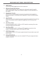
1
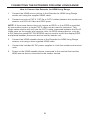
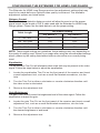
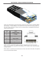
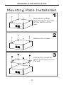
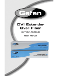
Extender for HDMI Long Range
GTV-HDMI-CAT5LR
User Manual
www.gefentv.com
ASKING FOR ASSISTANCE
Technical Support:
Telephone
Fax
(818) 772-9100
(800) 545-6900
(818) 772-9120
Technical Support Hours:
8:00 AM to 5:00 PM Monday thru Friday.
Write To:
Gefen Inc.
c/o Customer Service
20600 Nordhoff St
Chatsworth, CA 91311
www.gefentv.com
[email protected]
Notice
Gefen Inc. reserves the right to make changes in the hardware, packaging and
any accompanying documentation without prior written notice.
Extender for HDMI Long Range is a trademark of Gefen Inc.
© 2008 Gefen Inc., All Rights Reserved
All trademarks are the property of their respective companies
Rev X1
CONTENTS
1
Introduction
2
Operation Notes
3
Features
4
Sender Unit Panel Layout
5
Sender Unit Panel Descriptions
6
Receiver Unit Panel Layout
7
Receiver Unit Panel Descriptions
8
Connecting The Extender For HDMI Long Range
9
Configuring The Extender For HDMI Long Range
10 Network Cable Wiring Diagram
11 Mounting Plate Installation
12 Specifications
13
Warranty
INTRODUCTION
Congratulations on your purchase of the Extender for HDMI Long Range. Your
complete satisfaction is very important to us.
Gefen TV
Gefen TV is a unique product line catering to the growing needs for innovative
home theater solutions. We specialize in total integration for your home theater,
while also focusing on going above and beyond customer expectations to ensure
you get the most from your hardware. We invite you to explore our distinct
product line and hope you find your solutions. Don’t see what you are looking for
here? Please call us so we can better assist you with your particular needs.
The Gefen TV Extender for HDMI Long Range
The GefenTV HDMI CAT5-LR sends HDMI signals up to 825 feet (250m) away
from your HDMI source using just two widely available and inexpensive CAT5
cables (only one cable if the display’s EDID is remembered by source equipment). The HDMI CAT5-LR extender is also capable of supporting computer
video (DVI-D) when used with a DVI-to-HDMI cable, adding versatility. There are
no compromises with this solution -- video resolutions up to 1080p are delivered
in perfect digital purity accompanied with 7.1 digital audio for a full multimedia
experience at the remote destination.
How It Works
The GefenTV HDMI CAT5-LR Sender sits next to the source (computer, set-top
box or DVD player). The supplied cable connects an HDMI source to the HDMI
CAT5-LR Sender unit. The GefenTV HDMI CAT5-LR Receiver sits next to the
HDTV display -- up to 825 feet away. The HDTV display plugs into the GefenTV
HDMI CAT5-LR Receiver. Two CAT5 cables link the HDMI CAT5-LR Sender and
Receiver units to each other. Power is connected to HDMI CAT5-LR Sender and
Receiver, and a vibrant HD picture results on the connected HDTV display at the
receiver.
Note: The GefenTV HDMI CAT5-LR is HDMI 1.2 and DVI 1.0 compliant. It does
not support HDCP.
1
OPERATION NOTES
READ THESE NOTES BEFORE INSTALLING OR
OPERATING THE EXTENDER FOR HDMI LONG RANGE
•
The Extender for HDMI Long Range uses 2 CAT-5, CAT-5e or CAT-6 cables
for extension. If field terminating cables, please adhere to the TIA/EIA-568-B
specification.
•
Maximum extension is 820 feet (250 meters) at a resolution of 1080p.
•
HDMI 1.2 compliant
•
Extender for HDMI Long Range is NOT HDCP compliant.
2
FEATURES
Features
•
Extends high definition displays up to 820 feet (250 meters) from the source
at 1080p
•
Supports resolutions up to 1080p, 2K, and 1920 x 1200
•
Audio and video are transmitted over the CAT-5 cables with zero signal loss
•
Eliminates equipment noise in the viewing environment
•
Equalizer/Gain control for optimal picture quality
•
Improved compensation for cable skew
•
HDMI 1.2 compliant
Package Includes
(1) Extender for HDMI Long Range Sender
(1) Extender for HDMI Long Range Receiver
(1) One 6 Foot HDMI Cable (M-M)
(2) 5V DC Power Supplies
(1) Set of Wall Mounting Plates
(1) User’s Manual
3
SENDER UNIT PANEL LAYOUT
Front Panel
1
Back Panel
2
3
4
4
5
SENDER UNIT PANEL DESCRIPTIONS
1
HDMI Input
Connect the HDMI source device to this input port.
2
RJ-45 Port (Video)
This port accepts an CAT-5, CAT-5e or CAT-6 cable for transmission of the video
and audio signals to the receiver.
3
RJ-45 Port (DDC)
This port accepts an CAT-5, CAT-5e or CAT-6 cable for connection to the
receiver. This cable will be used for DDC and HDCP data.
4
5V DC Power Input
Connect the included 5V DC power supply between this input and an open wall
power socket.
5
Power LED indicator
The LED will become active once the included 5V DC power supply has been
properly connected.
5
RECEIVER UNIT PANEL LAYOUT
Front Panel
1
Back Panel
2
3
4
5
6
6
7
8
RECEIVER UNIT PANEL DESCRIPTIONS
1
HDMI Output
Connect the HDMI capable device to this output port.
2
Distance Control Dip Switches
These 2 Dip Switches are used to adjust the video/audio signal for specific
CAT-5 cable lengths. Please use the table on page 9 for more information on
this setting.
3
Equalization Trim Pot
This Trim Pot is used to adjust the amount of equalization that is applied to
the incoming signal. This setting must be adjusted to receive the best possible
quality.
4
Gain Trim Pot
This Trim Pot is used to adjust the amount of gain that is applied to the incoming
signal. This setting is meant to adjust the brightness of the incoming video
signal.
5
RJ-45 Port (Video)
This port accepts an CAT-5, CAT-5e or CAT-6 cable for receiving of the video
and audio signals from the sender.
6
RJ-45 Port (DDC)
This port accepts an CAT-5, CAT-5e or CAT-6 cable for connection to the
sender. This cable will be used for DDC and HDCP data.
7
5V DC Power Input
Connect the included 5V DC power supply between this input and an open wall
power socket.
8
Power LED indicator
The LED will become active once the included 5V DC power supply has been
properly connected.
7
CONNECTING THE EXTENDER FOR HDMI LONG RANGE
How to Connect the Extender for HDMI Long Range
1.
Connect the HDMI source device to the Extender for HDMI Long Range
sender unit using the supplied HDMI cable.
2.
Connect one pair of CAT-5, CAT-5e or CAT-6 cables between the sender and
receiver unit’s RJ-45 Video and DDC ports.
NOTE: If the source device does not require an EDID, or if an EDID is provided
by some other means, a single CAT-5 cable can be used for extension. This
single cable solution will only use the CAT-5 cable connected between the RJ-45
Video ports on the sender and receiver units. An EDID storage device, such as
a DVI detective (part# EXT-DVI-EDIDN) can be used to record the display EDID
and placed between the source device and the sender unit.
3.
Connect the HDMI capable device to the Extender for HDMI Long Range
receiver unit using a user supplied HDMI cable.
4.
Connect the included 5V DC power supplies to both the sender and receiver
units.
5.
Power on the HDMI capable device connected to the receiver first and the
HDMI source device connected to the sender second.
8
CONFIGURING THE EXTENDER FOR HDMI LONG RANGE
The Extender for HDMI Long Range receiver has adjustment settings that may
need to be made before an optimal video quality is achieved. The available
adjustment options are listed below.
Distance Control
The Dip Switches related to distance control will allow the user to set the proper
signal output for the length of CAT-5 cable used with the Extender for HDMI Long
Range system. Please use the table below to set the proper setting:
Cable Length
Dip Switch Setting
Dip Switch 1
Dip Switch 2
0 - 165 Feet
OFF
OFF
166 - 330 Feet
ON
OFF
331 - 495 Feet
OFF
ON
496 - 820 Feet
ON
ON
NOTE: These length settings are guidelines. Actual settings may vary depending on
the quality of cabling used. If there is no image after using the recommended settings
above, please try the setting listed either below or above the one currently being
used.
Equalization
The equalization Trim Pot will eliminate video noise that may be present in the video
signal. Follow the steps below to adjust the equalization:
1.
Locate the equalization Trim Pot on the front panel of the receiver and insert
a small adjustment tool, such as a small flat headed screwdriver, into the
hole.
2.
Turn the Trim Pot in either a clockwise or counter-clockwise direction until
the video noise is eliminated.
3.
Remover the adjustment tool.
Gain (Brightness)
The gain Trim Pot will control the brightness level of the video signal. Follow the
steps below to adjust the gain:
4.
Locate the gain Trim Pot on the front panel of the receiver and insert a small
adjustment tool, such as a small flat headed screwdriver, into the hole.
5.
Turn the Trim Pot in either a clockwise or counter-clockwise direction until
the desired brightness is achieved.
6.
Remover the adjustment tool.
9
NETWORK CABLE WIRING DIAGRAM
Gefen has specifically engineered their products to work with the TIA/EIA-568-B
specification. Please adhere to the table below when field terminating cable for
use with Gefen products. Failure to do so may produce unexpected results and
reduced performance.
Pin
Color
1
Orange / White
2
Orange
3
Green / White
4
Blue
5
Blue / White
6
Green
7
Brown / White
8
Brown
12345678
CAT-5, CAT-5e, and CAT-6 cabling comes in stranded and solid core types.
Gefen recommends using solid core cabling. CAT-6 cable is also recommended
for best results.
Each cable run must be one continuous run from one end to the other. No splices
or use of punch down blocks.
10
MOUNTING PLATE INSTALLATION
Mounting Plate Installation
1
Remove the rubber
feet covering the screws
off the bottom of the
unit.
Remove the screws.
2
3
Line up the mounting
plates and screw it on to
the unit.
11
SPECIFICATIONS
Video Amplifier Bandwidth ....................................................................... 165 MHz
Single Link Range/Max. Resolution ........................................ 1080p/1920 x 1200
Input Video Signal .............................................................................. 1.2 Volts p-p
Input DDC Signal ......................................................................... 5 Volts p-p (TTL)
HDMI Connector ................................................................ Type A, 19 Pin Female
Link Connector .............................................................................. RJ-45 Shielded
Power Supply/Power Consumption .................................... 5V DC / 20 watts max.
Dimensions ................................................................................ 5” W x 1” H x 5” D
Shipping Weight ............................................................................................ 3 lbs.
12