1
Print Server Reference Manual
For the Lantronix Family of Ethernet Print Servers
The information in this guide may change without notice. The manufacturer assumes no responsibility for any errors
which may appear in this guide.
UNIX is a registered trademark of The Open Group. Ethernet is a trademark of XEROX Corporation. DEC and LAT
are trademarks of Digital Equipment Corporation. Centronics is a registered trademark of Centronics Data Computer
Corp. PostScript is a trademark of Adobe Systems, Inc. NetWare is a trademark of Novell Corp. AppleTalk, Chooser,
and Macintosh are trademarks of Apple Computer Corp. LaserJet and Bitronics are trademarks of Hewlett Packard.
Windows is a trademark of Microsoft.
Copyright 2000, Lantronix. All rights reserved. No part of the contents of this book may be transmitted or reproduced
in any form or by any means without the written permission of Lantronix. Printed in the United States of America.
The revision date for this manual is 30, October 2000.
Part Number: 900-065A
Rev. A
WARNING
This equipment has been tested and found to comply with the limits for a Class A digital device pursuant to Part 15 of
FCC Rules. These limits are designed to provide reasonable protection against such interference when operating in a
commercial environment. This equipment generates, uses, and can radiate radio frequency energy, and if not installed
and used in accordance with this guide, may cause harmful interference to radio communications.
Operation of this equipment in a residential area is likely to cause interference in which case the user, at his or her own
expense, will be required to take whatever measures may be required to correct the interference.
Changes or modifications to this device not explicitly approved by Lantronix will void the user’s authority to operate
this device.
Cet appareil doit se soumettre avec la section 15 des statuts et règlements de FCC. Le fonctionnement est subjecté aux
conditions suivantes:
(1) Cet appareil ne doit pas causer une interférence malfaisante.
(2) Cet appareil doît accepter n'importé quelle interférence reìue qui peut causer uneopération indésirable.
Contents
1: Introduction............................................................................................................. 1-1
1.1 Product Overview ........................................................................................................... ............1-1
1.2 Protocol Support ........................................................................................................... ..............1-1
1.3 Terms ...................................................................................................................... ....................1-2
1.4 Server Features ............................................................................................................ ...............1-2
1.5 How To Use This Manual..................................................................................................... ......1-4
2: Concepts ................................................................................................................. 2-1
2.1 Services ................................................................................................................... ....................2-1
2.2 Network Protocols .......................................................................................................... ............2-1
2.3 AppleTalk .................................................................................................................. .................2-1
2.3.1 Addressing ............................................................................................................... ...2-2
2.3.2 Zones...........................................................................................................................2-2
2.3.3 Name Binding Protocol (NBP) ...................................................................................2-3
2.4 LAN Manager .............................................................................................................................2-3
2.4.1 Networking .................................................................................................................2-3
2.5 LAT.............................................................................................................................................2-4
2.6 TCP/IP ........................................................................................................................................2-5
2.6.1 IP Addresses ...............................................................................................................2-5
2.6.2 Dynamic Host Control Protocol (DHCP) ...................................................................2-6
2.6.3 Simple Network Management Protocol (SNMP) .......................................................2-6
2.6.4 Reverse Telnet (RTEL)...............................................................................................2-7
2.6.5 LPR Support ...............................................................................................................2-7
2.6.6 TCP/IP Utilities and Commands ................................................................................2-7
2.7 NetWare .....................................................................................................................................2-8
2.7.1 Networking .................................................................................................................2-8
2.7.2 Access Lists ................................................................................................................2-9
2.8 PostScript ....................................................................................................................................2-9
2.9 Security .....................................................................................................................................2-10
2.9.1 Event Reporting/Logging .........................................................................................2-10
3: Getting Started........................................................................................................ 3-1
3.1 Configuration Methods ...............................................................................................................3-1
3.1.1 EZWebCon .................................................................................................................3-1
3.1.2 Using a Web Browser .................................................................................................3-2
3.1.3 Command Line Interface ............................................................................................3-2
3.2 Entering and Editing Commands ................................................................................................3-3
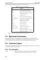
3.3 Restricted Commands .................................................................................................................3-4
3.4 Command Types .........................................................................................................................3-4
3.4.1 Set and Define.............................................................................................................3-4
3.4.2 Show, Monitor, and List .............................................................................................3-5
3.4.3 Clear and Purge...........................................................................................................3-5
3.5 Abbreviating Keywords ..............................................................................................................3-5
3.6 Maintenance Issues .....................................................................................................................3-5
i
Contents
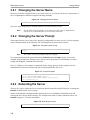
3.6.1 Changing the Server Name .........................................................................................3-6
3.6.2 Changing the Server Prompt.......................................................................................3-6
3.6.3 Rebooting the Server ..................................................................................................3-6
3.6.4 Restoring Factory Defaults .........................................................................................3-7
3.6.5 Reloading Operational Software.................................................................................3-7
3.7 Editing the Boot Parameters .......................................................................................................3-7
3.8 System Passwords.......................................................................................................................3-8
3.8.1 Privileged Password....................................................................................................3-8
3.8.2 Login Password ..........................................................................................................3-9
3.8.3 Maintenance Password ...............................................................................................3-9
3.9 Configuration Files .....................................................................................................................3-9
3.9.1 Using EZWebCon.....................................................................................................3-10
3.9.2 Without EZWebCon .................................................................................................3-10
4: Server Configuration .............................................................................................. 4-1
4.1 General Server Parameters..........................................................................................................4-1
4.1.1 Enabling Incoming Connections.................................................................................4-1
4.1.2 Enabling Server-Wide Port Characteristics ................................................................4-1
4.1.3 Enabling Announcements ...........................................................................................4-2
4.2 AppleTalk Server Parameters .....................................................................................................4-2
4.3 LAT Server Parameters ..............................................................................................................4-3
4.3.1 Server Identification ...................................................................................................4-3
4.3.2 Network Timers ..........................................................................................................4-3
4.3.3 Node Limit..................................................................................................................4-3
4.4 NetWare Server Parameters........................................................................................................4-4
4.4.1 Routing and Encapsulation .........................................................................................4-4
4.4.2 NetWare Access Lists.................................................................................................4-4
4.5 TCP/IP Server Parameters ..........................................................................................................4-5
4.5.1 IP Address...................................................................................................................4-5
4.5.2 Other TCP/IP Parameters ...........................................................................................4-5
4.5.3 Host Limit...................................................................................................................4-6
4.6 Creating Services ........................................................................................................................4-6
4.6.1 Creating a Simple Service (A Line Printer)................................................................4-7
4.6.2 Setting Up a Service With Group Codes ....................................................................4-8
4.6.3 TCP/Telnet Service Sockets .......................................................................................4-8
4.6.4 Enabling Other Service Options .................................................................................4-9
4.6.5 Setting Up a Modem Service ....................................................................................4-10
4.7 Security .....................................................................................................................................4-10
4.7.1 Controlling Incoming Sessions.................................................................................4-11
4.7.2 IP Security Table ......................................................................................................4-11
4.7.3 SNMP Security .........................................................................................................4-13
4.8 Event Logging...........................................................................................................................4-13
4.8.1 Configuring Host Types ...........................................................................................4-13
4.8.2 Host Name Formats ..................................................................................................4-13
4.8.3 Event Classes ............................................................................................................4-14
5: Ports......................................................................................................................... 5-1
5.1 Port Commands.............................................................................................................. .............5-1
5.1.1 Port Access .............................................................................................................. ...5-1
5.1.2 Serial Configuration....................................................................................................5-2
ii
Contents
5.1.3 Virtual Ports............................................................................................................ ....5-4
5.2 Other Port Characteristics ...........................................................................................................5-5
5.2.1 DTRwait .....................................................................................................................5-5
5.2.2 Port Names..................................................................................................................5-5
5.3 Security .......................................................................................................................................5-5
5.3.1 Password Restrictions .................................................................................................5-5
5.3.2 Preventing Access Until DSR Is Asserted..................................................................5-6
5.3.3 Automatic Logouts .....................................................................................................5-6
6: Using the Server ..................................................................................................... 6-1
6.1 Logging In and Out.....................................................................................................................6-1
6.1.1 Logging In ..................................................................................................................6-1
6.1.2 Logging Out................................................................................................................6-1
6.2 Configuring Your Port ................................................................................................................6-1
6.2.1 Privileged Port Commands .........................................................................................6-1
6.3 Local Server Commands.............................................................................................................6-2
6.3.1 Logout.........................................................................................................................6-2
6.3.2 Test Port......................................................................................................................6-2
6.4 Status Displays............................................................................................................................6-2
7: TCP/IP Host Setup .................................................................................................. 7-1
7.1 Selecting A Printing Method ......................................................................................................7-1
7.2 LPR Printing ...............................................................................................................................7-2
7.2.1 LPR Basics..................................................................................................................7-3
7.2.2 LPR on Windows NT 3.5.1 (and later).......................................................................7-4
7.2.3 LPR on AIX Hosts......................................................................................................7-6
7.2.4 LPR on HP Hosts........................................................................................................7-8
7.2.5 LPR on SCO UNIX Hosts ..........................................................................................7-9
7.2.6 LPR on Sun Solaris Hosts.........................................................................................7-10
7.3 Reverse Telnet (RTEL).............................................................................................................7-10
7.3.1 Components of RTEL...............................................................................................7-10
7.3.2 Installing Reverse Telnet Software...........................................................................7-11
7.3.3 Queueing with the RTEL Software ..........................................................................7-12
7.3.4 Setting up the RTEL Backend Filter ........................................................................7-12
7.3.5 Setting up the RTEL Named Pipe Daemon ..............................................................7-15
7.3.6 Creating a BSD Print Queue Using RTELPD ..........................................................7-17
7.3.7 Creating a SYSV Print Queue Using RTELPD........................................................7-17
7.3.8 RTEL Troubleshooting .............................................................................................7-18
7.4 TCP Socket Connections ..........................................................................................................7-18
7.5 PostScript Configuration...........................................................................................................7-19
8: NetWare Host Setup ............................................................................................... 8-1
8.1 Access Lists ............................................................................................................... .................8-1
8.2 Licensing NDS.............................................................................................................. ..............8-1
8.3 Printing .................................................................................................................. .....................8-2
8.3.1 Creating NDS Print Queues with PCONSOLE ..........................................................8-3
8.3.2 Creating Print Queues with NetWare Administrator..................................................8-4
8.3.3 Creating Bindery Print Queues with QINST ..............................................................8-6
8.3.4 Installing a Print Queue Using PCONSOLE ..............................................................8-7
8.3.5 Configuring Rprinter ..................................................................................................8-9
iii
Contents
8.4 PCL ........................................................................................................................ ...................8-15
8.5 PostScript ..................................................................................................................................8-15
8.6 Troubleshooting ........................................................................................................................8-15
8.6.1 QINST Print Queue Troubleshooting .......................................................................8-15
8.6.2 NDS Print Queue Troubleshooting...........................................................................8-16
8.6.3 NetWare Host Troubleshooting ................................................................................8-18
9: LAT Host Setup....................................................................................................... 9-1
9.1 Printing from LAT .......................................................................................................... ............9-1
9.1.1 Printing to an Application Port ...................................................................................9-1
9.1.2 Printing to a Service....................................................................................................9-2
9.1.3 Printing PostScript ......................................................................................................9-3
9.1.4 Printing Using DCPS Software ..................................................................................9-4
9.2 Troubleshooting ..........................................................................................................................9-4
9.2.1 VMS Printer Troubleshooting ....................................................................................9-4
9.2.2 VMS Host Troubleshooting........................................................................................9-6
10: AppleTalk Host Setup......................................................................................... 10-1
10.1 Configuration ............................................................................................................. .............10-1
10.1.1 Bitronics Interface ..................................................................................................10-1
10.1.2 Macintosh Service Configuration ...........................................................................10-2
10.2 Printing from a Macintosh ......................................................................................................10-2
10.2.1 Using AppleTalk on UNIX or VMS.......................................................................10-2
10.2.2 Using LaserPrep......................................................................................................10-2
10.2.3 Printing Bitmap Graphics .......................................................................................10-2
10.3 Troubleshooting Macintosh Printing ......................................................................................10-3
10.3.1 General Troubleshooting ........................................................................................10-3
10.3.2 Host Troubleshooting .............................................................................................10-5
11: LAN Manager Host Setup................................................................................... 11-1
11.1 Printing Methods.....................................................................................................................11-1
11.1.1 DLC .......................................................................................................................11-1
11.1.2 NetBIOS .................................................................................................................11-3
11.2 Windows NT Troubleshooting ...............................................................................................11-4
12: Command Reference.......................................................................................... 12-1
12.1 Overview.................................................................................................................. ...............12-1
12.2 Command Line Interface ........................................................................................................12-1
12.2.1 Command Completion............................................................................................12-1
12.2.2 Command Line Editing...........................................................................................12-2
12.3 Clear/Purge Commands ..........................................................................................................12-2
12.3.1 Clear/Purge IPsecurity ............................................................................................12-2
12.3.2 Clear/Purge Protocol NetWare Access ...................................................................12-3
12.3.3 Clear/Purge Service ................................................................................................12-3
12.3.4 Clear/Purge SNMP .................................................................................................12-4
12.4 Cls ...........................................................................................................................................12-4
12.5 Crash 451 ................................................................................................................................12-5
12.6 Define......................................................................................................................................12-5
12.7 Fg ............................................................................................................................................12-5
12.8 Finger ......................................................................................................................................12-5
iv
Contents
12.9 Help.........................................................................................................................................12-6
12.10 Initialize ................................................................................................................................12-7
12.11 List ........................................................................................................................................12-8
12.12 Logout...................................................................................................................................12-8
12.13 Man .......................................................................................................................................12-8
12.14 Mode .....................................................................................................................................12-8
12.15 Monitor .................................................................................................................................12-9
12.16 Netstat ...................................................................................................................................12-9
12.17 Ping .......................................................................................................................................12-9
12.18 Purge ...................................................................................................................................12-10
12.19 Remove Queue....................................................................................................................12-10
12.20 Save.....................................................................................................................................12-11
12.21 Set/Define IPsecurity ..........................................................................................................12-12
12.22 Set/Define Logging.............................................................................................................12-13
12.23 Set Noprivileged .................................................................................................................12-14
12.24 Set/Define Port Commands ................................................................................................12-15
12.24.1 Define Port Access .............................................................................................12-15
12.24.2 Set/Define Port Bitronics ....................................................................................12-16
12.24.3 Set/Define Port Character Size ...........................................................................12-16
12.24.4 Set/Define Port Command Completion ..............................................................12-17
12.24.5 Set/Define Port DSRlogout.................................................................................12-17
12.24.6 Set/Define Port DTRwait....................................................................................12-18
12.24.7 Set/Define Port Flow Control .............................................................................12-19
12.24.8 Set/Define Port Inactivity Logout.......................................................................12-20
12.24.9 Define Port Modem Control ...............................................................................12-20
12.24.10 Set/Define Port Name .......................................................................................12-21
12.24.11 Set/Define Port Parity .......................................................................................12-21
12.24.12 Set/Define Port Passflow ..................................................................................12-22
12.24.13 Set/Define Port Password .................................................................................12-22
12.24.14 Set/Define Port Printer......................................................................................12-23
12.24.15 Set/Define Port Signal Check ...........................................................................12-23
12.24.16 Set/Define Port Speed.......................................................................................12-24
12.24.17 Set/Define Port Stop .........................................................................................12-25
12.24.18 Set/Define Port Type ........................................................................................12-25
12.24.19 Set/Define Port Username ................................................................................12-26
12.24.20 Set/Define Port Verification .............................................................................12-26
12.25 Set/Define Printer Type ......................................................................................................12-27
12.26 Set Privileged/Noprivileged................................................................................................12-28
12.27 Set/Define Protocols Commands ........................................................................................12-28
12.27.1 Define Protocols AppleTalk ...............................................................................12-28
12.27.2 Define Protocols IP.............................................................................................12-29
12.27.3 Define Protocols LAN Manager .........................................................................12-30
12.27.4 Set/Define Protocols LAT ..................................................................................12-30
12.27.5 Set/Define Protocols NetWare............................................................................12-31
12.28 Set/Define Server Commands.............................................................................................12-34
12.28.1 Set/Define Server Announcements.....................................................................12-34
12.28.2 Set/Define Server Bootgateway..........................................................................12-35
12.28.3 Set/Define Server BOOTP..................................................................................12-35
12.28.4 Set/Define Server Buffering ...............................................................................12-35
12.28.5 Set/Define Server Circuit Timer .........................................................................12-36
v
Contents
12.28.6 Set/Define Server DHCP ....................................................................................12-36
12.28.7 Set/Define Server Gateway.................................................................................12-37
12.28.8 Set/Define Server Host Limit .............................................................................12-37
12.28.9 Set/Define Server Identification .........................................................................12-38
12.28.10 Set/Define Server Inactivity Timer...................................................................12-38
12.28.11 Set/Define Server Incoming .............................................................................12-39
12.28.12 Set/Define Server IPaddress .............................................................................12-40
12.28.13 Set/Define Server Keepalive Timer..................................................................12-40
12.28.14 Set/Define Server Loadhost ..............................................................................12-41
12.28.15 Set/Define Server Lock.....................................................................................12-41
12.28.16 Set/Define Server Login Password ...................................................................12-42
12.28.17 Set/Define Server Maintenance Password........................................................12-42
12.28.18 Set/Define Server Multicast Timer ...................................................................12-43
12.28.19 Set/Define Server Name ...................................................................................12-43
12.28.20 Set/Define Server NetWare Loadhost ..............................................................12-43
12.28.21 Set/Define Server NetWare Printserver............................................................12-44
12.28.22 Set Server NetWare Reset ................................................................................12-44
12.28.23 Set/Define Server Node Limit ..........................................................................12-45
12.28.24 Set/Define Server Password Limit....................................................................12-45
12.28.25 Set/Define Server Privileged Password ............................................................12-46
12.28.26 Set/Define Server Prompt .................................................................................12-46
12.28.27 Set/Define Server Queue Limit ........................................................................12-47
12.28.28 Set/Define Server RARP ..................................................................................12-48
12.28.29 Set/Define Server Reload .................................................................................12-48
12.28.30 Set/Define Server Retransmit Limit .................................................................12-48
12.28.31 Set/Define Server Secondary ............................................................................12-49
12.28.32 Set/Define Server Serial Delay .........................................................................12-49
12.28.33 Set/Define Server Service Groups ....................................................................12-49
12.28.34 Define Server Silentboot...................................................................................12-50
12.28.35 Set/Define Server Software ..............................................................................12-50
12.28.36 Set/Define Server Startupfile ............................................................................12-51
12.28.37 Set/Define Server Subnet Mask........................................................................12-52
12.29 Set/Define Service Commands ...........................................................................................12-53
12.29.1 Set/Define Service ..............................................................................................12-53
12.29.2 Set/Define Service AppleTalk ............................................................................12-53
12.29.3 Set/Define Service Banner..................................................................................12-53
12.29.4 Set/Define Service Binary ..................................................................................12-54
12.29.5 Set/Define Service Default .................................................................................12-54
12.29.6 Set/Define Service DLC .....................................................................................12-55
12.29.7 Set/Define Service EOJ ......................................................................................12-55
12.29.8 Set/Define Service Formfeed..............................................................................12-56
12.29.9 Set/Define Service Identification........................................................................12-56
12.29.10 Set/Define Service LAN Manager....................................................................12-57
12.29.11 Set/Define Service LAT ...................................................................................12-57
12.29.12 Set/Define Service NetWare.............................................................................12-57
12.29.13 Set/Define Service Password ............................................................................12-58
12.29.14 Set/Define Service Ports ...................................................................................12-58
12.29.15 Set/Define Service PostScript...........................................................................12-59
12.29.16 Set/Define Service PSConvert ..........................................................................12-59
12.29.17 Set/Define Service RTEL .................................................................................12-59
vi
Contents
12.29.18 Set/Define Service SOJ.....................................................................................12-60
12.29.19 Set/Define Service TCPport .............................................................................12-60
12.29.20 Set/Define Service Telnetport...........................................................................12-61
12.30 Set/Define SNMP ...............................................................................................................12-61
12.31 Show/Monitor/List Commands...........................................................................................12-62
12.31.1 Show/Monitor/List IPsecurity ............................................................................12-62
12.31.2 Show/Monitor/List Logging ...............................................................................12-62
12.31.3 Show/Monitor/List Ports ....................................................................................12-63
12.31.4 Show/Monitor/List Protocols..............................................................................12-64
12.31.5 Show/Monitor Queue..........................................................................................12-67
12.31.6 Show/Monitor/List Server ..................................................................................12-68
12.31.7 Show/Monitor/List Services ...............................................................................12-72
12.31.8 Show/Monitor/List SNMP..................................................................................12-72
12.31.9 Show/Monitor Users ...........................................................................................12-73
12.31.10 Show Version....................................................................................................12-73
12.32 Source .................................................................................................................................12-73
12.33 Stty ......................................................................................................................................12-74
12.34 Su ........................................................................................................................................12-74
12.35 Test Loop ............................................................................................................................12-75
12.36 Test Port ..............................................................................................................................12-75
12.37 Test Service.........................................................................................................................12-76
12.38 Who.....................................................................................................................................12-77
12.39 Zero Counters .....................................................................................................................12-77
A: Contact Information ...............................................................................................A-1
A.1 Problem Report Procedure........................................................................................................ A-1
A.2 Full Contact Information........................................................................................................... A-1
B: Troubleshooting.....................................................................................................B-1
B.1 Power-up Troubleshooting........................................................................................................ B-1
B.2 DHCP Troubleshooting............................................................................................................. B-2
B.3 BOOTP Troubleshooting .......................................................................................................... B-2
B.4 RARP Troubleshooting............................................................................................................. B-3
B.5 Printing Problems...................................................................................................................... B-3
B.6 PostScript Problems .................................................................................................................. B-3
C: Updating Software .................................................................................................... 5
C.1 Obtaining Software ....................................................................................................................... 5
C.2 Reloading Software....................................................................................................................... 6
C.3 Troubleshooting Flash ROM Updates ..........................................................................................8
Glossary
Index
vii
1: Introduction
1.1 Product Overview
The Lantronix Print Servers (EPS, MPS, and LPS models) are multi-protocol print servers that provide
shared network access to printers for a variety of network protocols and operating systems. The print servers
generally support the TCP/IP, IPX (NetWare), and Local Area Transport (LAT), AppleTalk (EtherTalk),
and Microsoft LAN Manager protocols. They can queue multiple pending jobs and service those jobs in the
order in which they are received from hosts.
Note:
The LPS does not support AppleTalk or LAT.
For a description of your individual print server model, please refer to the Installation Guide that came with
your print server.
Lantronix servers store their executable software in Flash (rewritable) ROM, meaning that they do not have
to download software from a host each time they boot. Software must only be downloaded when a new
software version becomes available. See Appendix D for more information.
Note:
In this manual, all servers will be referred to as “the Server” unless a distinction
needs to be made between models.
1.2 Protocol Support
The Server supports five industry-standard network protocols:
TCP/IP
TCP/IP is a widely-used protocol that can be run on networks with Macintoshes, PCs, and Unix
workstations. Server support includes Telnet, Rlogin, and the LPR and RTEL printing systems.
NetWare (IPX/SPX )
NetWare allows devices attached to the Server to act as networked printers. The Server supports all
NetWare frame types: Ethernet v2, Native Mode (802.3), 802.2, and 802.2 SNAP. In addition, it
supports both Bindery mode and NetWare Directory Services (NDS).
Local Area Transport (LAT)
LAT is a protocol developed by Digital Equipment Corporation for local network terminal connections and is supported on almost all Digital operating systems. It provides both logins to remote
hosts and host-initiated print spooling.
AppleTalk
AppleTalk allows networked Apple Macintosh computers to see devices attached to the Server and
access them as they would any networked printer.
LAN Manager
The Server allows devices on LAN Manager networks to access networked printers. Systems running Windows NT can access the devices using the Digital Network Port for Windows NT or the
NetBIOS protocol.
1-1
Terms
Introduction
1.3 Terms
In this manual, the following terms are used to describe parts of a network. See the Glossary for more
detailed explanations of these terms.
host
A computer, sometimes referred to as a CPU, attached to the network. The
term host
node
Any intelligent device directly connected to the Ethernet network and having
its own Ethernet addresses, such as a host, an Ethernet printer, or a terminal or
print server. Devices connected to the Server are not nodes.
service
A resource that can be accessed locally or via the network. For example, a host
is a service to which terminals can connect. The Server can offer its attached
printers to the network as services.
Local mode
The Server user interface, which is used to issue configuration commands and
establish sessions with services.
1.4 Server Features
AppleTalk Support
The Server provides Ethernet access to attached laser printers; Server print services appear in the
Macintosh Chooser window like any other printer on the network. Bi-directional communication
(either a serial or IEEE 1284 parallel interface) is required.
LAN Manager Support
The Server can be configured to appear as a print node to other LAN Manager nodes. Supported
systems include Windows NT and Windows 95.
LAT and Digital Compatibility
The Server supports LAT and TSM/NCP, making it fully compatible with most Digital Equipment
Corporation operating environments.
NetWare Support
The Server is used primarily for print serving. The Server can also be configured and logged into
from a NetWare fileserver, and can function as a print node for other NetWare fileservers.
TCP/IP and UNIX Compatibility
Almost all UNIX systems support Telnet, an established industry standard. Telnet can be used for
logging into the server to issue configuration commands. UNIX systems generally implement Rlogin as well, unless security considerations dictate that it be disabled at a particular site.
Small Size
The small, attractive case is designed to fit into any office environment. Because there is no internal
fan, the Server operates silently.
Ease of Use
The server’s Local mode supports command line editing, command line recall, and command completion. An extensive Help facility is also provided.
1-2
Introduction
Server Features
Easy Configuration
The EZWebCon utility (provided on CD-ROM) allows users to configure the Server from a any
host machine running the Java Virtual Machine (JVM).
Note:
You must be Supervisor to run the EZWebCon utility on a NetWare client.
Remote Configuration
The Server can be logged into and remotely configured using one of the following methods:
❍
Digital’s NCP and TSM facilities
❍
The Telnet console port, similar to the NCP remote console
❍
The network login feature, which allows managers to log into the Server via TCP/IP, LAT, and
NetWare.
❍
EZWebCon, a configuration application that runs on any host computer running the Java Virtual
Machine (JVM).
Command Line Interface
A simple but powerful command interface is provided for both users and system managers. The
Server operating code is downloaded automatically at power-up, making software upgrades as easy
as copying a file.
The Server stores its operating software permanently on-board, so it does not need to download
code unless new versions become available. Servers can also be configured to request a downloaded
configuration file at boot time.
The Command Reference chapter of this reference manual describes the commands available in the
Server’s local command line mode. These commands control port and server configuration
Note:
See the Command Reference for more information on the command line,
command recall, and command completion features.
Context-Sensitive Help
Context-sensitive on-line help is available at any point. You may type “HELP” by itself for overall
help, “HELP command” for help on a specific command, or a partial command line followed by a
question mark for help on what is appropriate at that particular point.
Note:
See Help on page 12-6 for more information.
Host-Initiated Connections
The Server may be configured to provide its attached devices as services to other nodes, allowing
hosts to share printers. AppleTalk, LAN Manager, LAT, NetWare, and TCP/IP hosts can queue jobs
to Server services simultaneously. The optional RTEL host software provides both printer backend
access and a named pipe interface to the Server from TCP/IP hosts.
Security
The Server includes several configurable security features. They include:
❍
Group codes, which allow the Server to act as a filter to limit the user’s knowledge of, and access
to, specific services.
1-3
How To Use This Manual
Introduction
❍
Automatic session logouts when a port is disconnected or a device is turned off.
❍
Password protection for privileges, ports, services, maintenance commands, and the remote
console.
DHCP Support
The Server can obtain an IP address from a DHCP server at boot time.
SNMP Support
The Server supports the Simple Network Management Protocol (SNMP), which can be used by network managers to monitor network load and error conditions. No enterprise-specific MIBs are supplied by Lantronix.
Diagnostics
Power-up and interactive diagnostics help system managers troubleshoot network and serial line
problems.
1.5 How To Use This Manual
The rest of the chapters in this manual describe the features and commands of the Server. Information is
broken down as follows:
◆
Chapters 2 through 6 cover general functionality:
◆
Chapter 2, Concepts, explains the basic ideas behind Server operation.
◆
Chapter 3, Getting Started, explains available configuration methods, as well as steps needed for
reconfiguration and maintenance operation.
◆
Chapter 4, Server Configuration, explains server-wide configuration options, including protocolspecific configuration and security issues.
◆
Chapter 5, Ports, details the port-specific configuration options
◆
Chapters 7 through 11 cover protocol-specific issues and troubleshooting:
❍
Chapter 7 covers TCP/IP Host Setup for LPR and RTEL printing.
❍
Chapter 8 covers NetWare Host Setup needed for printing.
❍
Chapter 9 covers LAT Host Setup for VMS printing.
❍
Chapter 10 covers AppleTalk Host Setup needed for printing.
❍
Chapter 11 covers LAN Manager Host Setup needed for printing.
◆
Chapter 12, Command Reference, lists the Server command set in detail, including syntax, options,
errors, examples, and where to find related information.
◆
Appendices provide supplementary information, including Technical Support contact information,
troubleshooting tips, and pinout information.
Note:
1-4
Installation and cabling are covered in your Server’s Installation Guide.
2: Concepts
2.1 Services
Services are the basic method of connecting to the Server from any host or another server. In general, a
service is required on the Server before any job or connection queueing will take place. See the Server
Configuration chapter for details on creating and using services.
2.2 Network Protocols
A network protocol describes the data contained in Ethernet packets. The network protocols provided by the
Server are completely separate, other than the use of the Ethernet data layer. The following figure shows the
protocol stacks supported by the Server.
Figure 2-1: Supported Network Protocols
AppleTalk
LAN Manager
Printer
SMB
Access Protocol
ATP
LAT
NetWare
TCP/IP
LAT
NCP
Telnet/ Rlogin/ RTEL/
lpd
SPX
TCP
IPX
IP
NetBEUI
DDP
Ethernet/IEEE 802.3 Data Layer
There are three different Ethernet frame formats, one of which is subdivided:
◆
What is typically called Ethernet is technically referred to as Ethernet v2. This is the default frame
type for most TCP/IP, LAT, and MOP/NCP protocol stacks. It can also be used for NetWare.
◆
The IEEE 802.2 frame format comes with either a regular or a SNAP SAP (Service Access Point).
AppleTalk uses the SNAP format by default. Both types can be used by NetWare.
◆
NetWare 2.x and 3.x stations, by default, do not use any of these frame types. They use a native mode
format that is being phased out.
2.3 AppleTalk
AppleTalk is a protocol used primarily by Apple Macintoshes to access network resources such as file
servers and printers. AppleTalk is also available for UNIX, NetWare, and other operating systems. The
AppleTalk protocol can be run over Ethernet (EtherTalk), Token Ring (TokenTalk), or LocalTalk, which is
a medium speed network type built into every Macintosh. These various network media can be connected
with AppleTalk routers to allow all nodes to communicate with one another. The AppleTalk protocol
supports features such as file sharing and security in addition to printing.
2-1
AppleTalk
Concepts
The Server supports only the Printer Access Protocol (PAP) and therefore cannot create outgoing AppleTalk
sessions—only incoming print requests are accepted. Any services on the Server with AppleTalk enabled
will show up as LaserWriters in Macintosh Chooser windows and are associated with an available zone
(explained in Section 2.3.2). Users who select a Server service as their LaserWriter will have their print jobs
forwarded to the Server for printing, or for queueing if the print port on the Server is in use or otherwise
unavailable.
AppleTalk printing is different from printing in other protocols. There are standard Macintosh drivers
provided for specific Apple printer types, such as LaserWriters and ImageWriters, but there are no plain
ASCII line printers by default. ASCII jobs are converted into PostScript (for laser printers) or bitmaps (for
ImageWriters) when printed. Only laser printer devices are supported by the Server under AppleTalk.
The Macintosh client will need to query the printer about status, so only laser printers that reply to these
interactive PostScript requests can be used. The Server parallel ports support Bitronics mode, provided the
attached laser printer also implements it.
2.3.1 Addressing
AppleTalk provides for dynamic node addressing, allowing a node to choose its address at boot time. It will
send network packets to the other nodes to avoid choosing a node ID already in use. A node can also
discover its network number by listening for AppleTalk router broadcasts; if none are heard, a default
network number is chosen. The Server will save zone/network/node ID triplets in permanent memory,
which reduces traffic at reboot time, although the Server AppleTalk address may change across boots in
response to any network changes.
Network numbers are configured in the routers, so the only AppleTalk configuration supported by the
Server is the specification of a zone name other than the default. Due to the generally non-configurable
nature of AppleTalk, most AppleTalk devices are truly “plug-and-play”— they can be powered up and used
right out of the box.
2.3.2 Zones
Zones are arbitrary groupings of AppleTalk nodes used to organize resources into groups that are easier for
users to understand. For example, a college may organize zones around departments, like Math
Department and Physics Department. Zones allow users to sift through large numbers of nodes by
choosing those groups they are familiar with regardless of the organization of the network. In general, zones
need not have a correlation to physical or network location, thus any node can declare itself a member of
any single zone.
Zones, like nodes, originate from and are configured on AppleTalk routers. One zone on each network will
be chosen by the router as the default zone. If there are no AppleTalk routers on the network, there will be
only one zone (the default zone) of which all nodes are members. If no zone name has been previously
defined on the Server, or if the defined zone is no longer valid, the Server will join the default zone and no
other configuration is needed. The Server can be placed in a different zone with the Define Protocols
AppleTalk command. Each time the Server is booted, or when its zone is changed, it will verify the zone
name with a router.
2-2
Concepts
LAN Manager
2.3.3 Name Binding Protocol (NBP)
NBP is used by AppleTalk to advertise resources, such as printers and fileservers, to the network. Any
resource that other users can access will have NBP information that must be communicated to other nodes.
The items in the Chooser window reflect the NBP resources on the network.
NBP and the Chooser organize resources by three levels: name, type, and zone. Names are arbitrary strings
assigned by users, such as Kathy or MyPrinter. Types are generic classes of resources, such as Macintosh
IIci and LaserWriter. Zones, mentioned previously, are collections of nodes on the network. Typical
Macintosh NBP information might be [Kathy, Macintosh IIci, Accounting] for the name, type, and zone,
respectively. A service offered by the Server called MyPrinter that has AppleTalk enabled and that is
located in the Engineering zone would have an NBP description of [MyPrinter, LaserWriter, Engineering].
If the LaserWriter resource in the Engineering zone were selected in the Chooser, one of the resources
shown would be the MyPrinter service offered by the Server.
The NBP type LaserWriter designates a PostScript printer, so nodes printing to printers of type
LaserWriter assume that the printer supports PostScript. Care must be taken to attach only PostScript
printers to Server services with AppleTalk enabled, and to disable AppleTalk on services that do not support
PostScript printers. It is not possible to print to non-PostScript printers (for example, ImageWriters and
StyleWriters) from a Macintosh via the Server.
2.4 LAN Manager
LAN Manager is based on the NetBIOS protocol. It is used by several PC-based operating systems, notably
OS/2, Windows NT, and Windows for Workgroups, although LAN Manager servers have been written for
HP and Sun workstations. The Server implements only enough of the NetBIOS protocol stack to provide
print services to nodes; no interactive logins are allowed.
The Server also implements the straightforward and easy to use DLC printer protocol typically used by HP
laser printers. You must select the hardware address of the Server as the target for the print job. DLC
operation is only supported under Windows NT. DLC does not provide queueing on the Server, nor does it
allow printing to more than one service on the Server.
2.4.1 Networking
NetBIOS is not a routable protocol, so the Server can only communicate with local nodes or nodes that are
accessible via a gateway capable of bridging the NetBIOS data.
LAN Manager node lookups take a text resource name and resolve it into a hardware address. For this
reason, node and resource names must be unique on the network, and the Server will print an error message
if any configuration that violates this rule is attempted.
Note:
NetBIOS can be run over TCP/IP, but the Server does not support this mode of
operation.
2-3
LAT
Concepts
2.5 LAT
Digital Equipment Corporation’s LAT (Local Area Transport) networking software is designed to ease the
process of accessing and managing local area networks.
LAT is significantly different from other protocols in two important ways. First, LAT is not routable. There
is no way to divide LAT networks into smaller subnetworks and use routers to reduce traffic between nodes.
Second, LAT is a timer-driven protocol. Packets are expected at certain intervals, and the protocol cannot
adapt to slow network links dynamically. For these reasons, LAT traffic over wide areas is typically carried
inside (or encapsulated in) TCP/IP or IPX/SPX packets. The latter two protocols are fully routable, and
can handle wide-area, slow network links.
Note:
If LAT is bridged across slow links, session time-outs and errors are likely.
LAT software is built around the concept of services. A service may be provided by a dedicated device,
such as a printer, or by a network host. A device that offers one or more services, such as your Server, is
called a node.
In general, all services offered by the Server are associated with one or more ports; exceptions to this rule
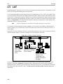
will be noted later. Figure 2-2 shows an example of services offered on a network.
Figure 2-2: Example of Network Services
EPS4
LANtronix
PWR
OK NET RCV XMT
1
Node Vax2, with
service Vax2
(logins to other
users)
0
Node Server_1, offering
service "modem"
Node Phred, a computer
offering services
"LaserPrinter" (for
printing) and "Phred"
(for logins)
Nodes advertise their services to the network by broadcasting occasional messages about them. These
messages, referred to as multicasts, contain the node’s name and its list of services. By monitoring
multicast messages, all hosts on the network know what nodes and services are available and can provide
this information to their interactive users. The Show Services and Show Nodes commands display this
information.
2-4
Concepts
TCP/IP
LAT multicast messages contain a rating for each service offered. Ratings range from 0 to 255; 0 means
the service is unavailable, while 255 means the service is available and has no current users. Ratings for a
given service may change over time. For example, the rating for a computer accepting logins will generally
change as its workload changes. Conversely, ratings for a modem are typically either 0 (in use) or 255 (not
in use). In the example above, the server with eight modems attached will continue to advertise that the
service “modem” is available (a 255 rating) until all eight modems are in use (a 0 rating).
Service ratings may concern even casual users, since they are used to determine which service a user will
be connected to whenever there is a choice. For example, if a user types Connect Hub and five nodes
offer service hub, the user will be connected to the least busy node automatically. In the case mentioned
above, where both the local Server and a remote node offered the same service, the ratings determine which
node will service the connection attempt.
Another major network management feature of LAT is the concept of service groups. Each port on the
Server and each service on the network can be thought of as belonging to one or more groups. When a user
or device requests a service connection, the LAT host will check to see if the groups to which the requester
belongs match those of the requested service. If any group number is common to both the requester and the
service, the connection attempt continues. If there are no common group numbers, the connection attempt
fails.
Note:
There may be additional access restrictions on the service, such as password
protection.
Suppose Bob is logged into port 4 on his Server and the server manager has given port 4 access to groups
1, 7, 13, and 105. Bob, or anyone else using port 4, can only access services that have one of those group
numbers. Suppose Bob wishes to access a modem on a different server. If the server to which the modem is
attached allows access to groups 8, 12, 16, 42, and 105; Bob will be allowed to use the modem because he
and the modem service have group 105 in common.
Note:
See Set/Define Port Authorized Groups on page 12-HIDDEN and Set/Define
Server Service Groups on page 12-49 for more information.
Group numbers also are useful to nodes because each node only needs to pay attention to multicasts that
involve its users’ groups. As a result, groups can hide services that would otherwise be visible. The server
manager can also hide services from a set of ports. Setting up and managing services and groups is discussed
in more detail in the Server Configuration chapter, next.
2.6 TCP/IP
2.6.1 IP Addresses
Every TCP/IP node on a network has an IP address, which is unique to that network and an Ethernet
Address, which is unique across all hardware in the world. The IP address provides information needed to
forward packets across multiple networks, if necessary.
The address is of the form n.n.n.n, where each n is a number from zero to 254, as in 192.0.0.1. The exception
is that there cannot be a zero in the last segment of the address.
Note:
The number 255 is strictly reserved for broadcast packets.
2-5
TCP/IP
Concepts
A unique IP address must be specified on the Server before any of the TCP/IP functionality is available. See
your Installation Guide for more information on configuring the IP address.
A DHCP server can be used to temporarily assign a leased IP address to the Server. See Dynamic Host
Control Protocol (DHCP) on page 12-6 for more information.
2.6.2 Dynamic Host Control Protocol (DHCP)
DHCP, an extension to BOOTP, allows network administrators to lease IP addresses to network nodes as
needed. Server servers offer two levels of DHCP support: boot and runtime.
If your Server has boot mode DHCP support, the Server will attempt to acquire an IP address via DHCP at
boot time. If it succeeds, the Server will save the IP address into NVR and continue with the boot process.
Once running, the Server’s operational code will attempt to acquire the same IP address from the DHCP
server. If for some reason the runtime DHCP request fails (for example, if there is no response for 15
seconds), the Server will use the address saved in NVR.
If your Server does not support DHCP at the boot level, you can still use DHCP at the operational level. To
enable DHCP in the runtime code, enter the Set/Define Server DHCP Enabled command and reboot the
server.
Note:
Enabling DHCP will remove the IP address saved in NVRAM, if there is one.
The Server will use BOOTP or RARP to acquire an IP address at boot time, and then it will request an IP
address via DHCP once it is running. If the runtime DHCP request fails, the server will use the IP address
stored in NVRAM. If the DHCP request succeeds, the Server will use the resulting IP address. It will not
save the IP address to NVRAM or overwrite the saved address (the one acquired by BOOTP or RARP).
If you enter a new IP address with the Set/Define Server IPaddress command, the Server will assume that
you want to use that address in the future, and will disable DHCP.
Note:
When DHCP is used, the IP address saved in NVRAM will change each time the
Server boots, and the List Server Bootparams command (which shows the
characteristics that will be in effect the next time the Server boots) may show a
different IP address than the one that is currently in use.
2.6.3 Simple Network Management Protocol (SNMP)
The Server supports the SNMP network protocol, which allows hosts on the network to query nodes for
counters and network statistics and change some parameters on those nodes. The form of these requests is
documented by RFC 1098. The list of items that can be queried and/or set and the type of data used, such
as integer and string, are both documented in various Management Information Bases (MIBs). MIBs cover
a variety of things, such as parallel port status, counters, and IP address resolution tables.
The Server supports the following MIBs:
MIB-II (RFC 1213)
System, Interface, Address Translation, IP, ICMP, TCP, and UDP, but not the
EGP group.
Parallel MIB (RFC 1660)All parallel devices.
Serial MIB (RFC 1659)All Serial devices.
2-6
Concepts
TCP/IP
The Server will respond to queries for unknown MIBs with a “not in MIB” error to the requesting host.
RFC’s 1065, 1066, and 1098 offer additional information on SNMP queries and the structure of the MIBs.
See Set/Define SNMP on page 12-61 for more information about configuring MIB usage.
Traps are sent to a host when an abnormal event occurs on the Server. The Server can generate limited
forms of three SNMP traps. It will generate a Coldstart trap when it first boots, and a Linkup trap when
the startupfile (if any) has been read from a host and normal operation commences. If a startupfile has been
configured but the download fails, the Server will send an Authentication trap. In all three cases, the trap
will be directed to the IP address of the Server’s loadhost. The Server will not generate traps for any other
cases.
Note:
To disable traps, define the Loadhost as “0.0.0.0” and reboot the server. See Set/
Define Server Loadhost on page 12-41 for syntax.
The Server has a local SNMP security table to restrict or prevent unauthorized SNMP configuration.
2.6.4 Reverse Telnet (RTEL)
When a server provides a service to a LAT host, the connection is often referred to as Reverse LAT. Reverse
Telnet allows a UNIX host to initiate connections to the Server in much the same way. It is called Reverse
Telnet because “normal” connections are logins from a server to a host.
Your Server comes with special software to add RTEL functionality to your UNIX host. RTEL connections
can be made through a back-end program for a printer, or through a named pipe. For example, you can print
files from your UNIX host to a printer attached to the Server through your host’s lp or lpr print system.
Server services do not care what hosts are using them. Multiple jobs from any of the supported protocols
can be queued simultaneously on any service.
2.6.5 LPR Support
The Server and many UNIX systems implement the lpr (Berkeley remote printing) protocol, a protocol that
makes it very easy to add print hosts to a system. To add the Server as a print host, add the Server’s IP
address to a host table and add the Server’s service name as a print queue. No special host software or other
configuration is needed. Server services can be accessed via the normal lpr commands on the host.
Print jobs can be forwarded multiple “hops” in the network. If you only want one host to know about Server
print queues, configure the other hosts to forward their print jobs to that host which will forward them to the
Server for printing.
Note:
See Chapter 7, TCP/IP Host Setup, for more information.
2.6.6 TCP/IP Utilities and Commands
The following commands have been added to help TCP/IP usability:
Finger
Displays users on local and remote hosts. The finger command by itself shows
all users on the Server. If given with a parameter, such as user@host, it shows
information regarding the named user on the specified host. The username can
be omitted, in which case all the users on the remote host will be displayed. If
the host cannot be reached or accessed, the finger command fails.
2-7
NetWare
Concepts
Note:
To see a list of Server processes, enter the command “finger finger.”
Netstat
Displays the status of the routing tables and current network sessions.
Ping
Sends a TCP/IP request for an echo packet to another network host to test
network connections.
2.7 NetWare
Novell’s NetWare software allows you to link computers together and provide file and printer sharing. It is
typically used to network DOS-based PCs, but is starting to appear under UNIX and other operating
systems. NetWare is built around file servers, which handle user logins, provide network resources, and
control security. At least one file server, such as a PC or UNIX host, is required in any NetWare
environment. NetWare users typically have to log into a file server to enjoy the networked (shared) benefits.
The Server supports a significant subset of the NetWare functionality, most notably print spooling.
Fileservers can be configured to send queued print jobs to printers attached to the Server. No special
software is required on the fileserver; configuration uses the EZWebCon Configuration software or the
standard PCONSOLE utility. Any user or application that can use NetWare print queues can spool jobs to
the Server.
The Server must periodically query the file servers for pending jobs. To do so, it logs into a file server to
access the print spooler, and will try to connect to all file servers on the local network (subject to access lists,
explained later) to check for such jobs. See Set/Define Server NetWare Loadhost on page 12-43 for more
information.
NetWare support also allows logins from fileservers to the Server (for configuration) and file downloading
(to download the system software at boot time).
2.7.1 Networking
Each NetWare node uses its hardware address as its node ID. In addition, the Server gets all the networking
information it needs from periodic broadcasts sent by NetWare routers on the network. It will learn its own
network number as well as routes to non-local file servers. No further configuration is needed.
The NetWare protocol can use all four Ethernet frame formats. It will listen for all frame formats, and then
use the correct one for the connection. The different frame types are treated as different networks, and thus
each frame type has a different network number. If there is only one frame format in use on the LAN, the
Server will use the network number for that frame type. If there are multiple frame types, limitations to the
NetWare protocol require that the Server use a different network number for each frame type on which it
wants to advertise itself.
The Server can use multiple frame types by creating a new, unique “internal network number” and
advertising itself as a router to the internal network. Any nodes or fileservers that need to communicate with
the Server use this new network number, and treat the Server as a router to that network. If this behavior is
not desired, the Server can be forced to use only one frame type (and thus not need an internal network
number).
2-8
Concepts
PostScript
2.7.2 Access Lists
Since NetWare networks can have hundreds of fileservers, the network needs a way to reduce the number
of Server queries, both to reduce network traffic and to prevent long delays in servicing active queues. By
using access lists (created with the Set/Define Protocols NetWare Access command on page 12-31) you
can control which file servers the Server will and won’t poll for print jobs.
The file servers have no control over the Server access lists, so they will never know if a misconfiguration
of the access list prevents them from spooling print jobs to the Server.
2.8 PostScript
Many printers (including all LaserWriters and other AppleTalk compatible laser printers) use a printing
language called PostScript. Unlike other printer protocols, which typically accept ASCII characters and
print them verbatim, PostScript is also a programming language. Shapes and fonts can be defined as
routines and re-used on successive pages, multiple fonts and copies can be printed, and text and diagrams
can be rotated and shifted on pages.
PostScript is also an interactive language, where the printing host can query the printer for its knowledge
about fonts and software versions. If the host expects to receive data from the printer (as is the case for all
AppleTalk printing), the printer must support Bitronics mode and be connected to a bidirectional port such
as one on the Server. PostScript printing from UNIX, LAT, and NetWare hosts, where bidirectional data
flow is not a requirement, can generally use any parallel port.
PostScript is a verbose language; it is recommended that the printer and Server use a baud rate of at least
9600 to communicate over serial lines. A baud rate of 38400 or better is strongly recommended for highoutput duty; see the printer’s documentation for information on changing the serial speed. Also, many
PostScript jobs contain 8-bit characters. The Server is configured for 8-bit characters, but if the printer is
not (the default on many laser printers is 7-bit), some characters will be printed incorrectly. See your
printer’s documentation for details on how to change the character size setting.
Due to the interactive nature of PostScript, it is possible for the printer and host to get out of synch in their
communication. Since the printer “interprets” the entire PostScript job and then prints the pages, it is
possible for the Server to complete the transfer and accept a new job while the printer is still digesting the
last job. For this reason, an end-of-job character (ASCII 0x4 or Ctrl-D) is used to end all PostScript jobs.
Typically the host will send one at the end of the job and the printer will reply with one when it is done
processing the job. For information on end-of-job characters, see Set/Define Service EOJ command on
page 12-55.
The Server will force a Ctrl-D character when PostScript is enabled on the appropriate service and wait for
one in return. Therefore, enabling PostScript is strongly recommended for all PostScript printer
applications. It guarantees that the printer is ready to accept new data when the job actually starts. Job loss
and printer hangs are the usual result if PostScript is not enabled on the service and the printer cannot keep
up with the job rate. High-speed printers may happen to work if the PostScript attribute is not enabled,
simply because they finish the current job in the time it takes for the Server to accept the next one.
2-9
Security
Concepts
2.9 Security
Several methods can be used to control access to the Server and restrict user behavior once logged in. For
example:
◆
Incoming logins can be selectively disabled and/or password protected via the Set/Define Server
Incoming command.
◆
The IP security table can be used to restrict logins to the Server.
◆
Ports used for network logins can be “preconfigured” with a standard set of characteristics for each
login.
For more information about security measures and restriction options, including some Server features that
are used for more than security reasons, see the Server Configuration and Ports chapters.
2.9.1 Event Reporting/Logging
The Server can be configured to report various errors and events either to the serial console port or to a
network host via TCP/IP (using the syslogd facility), LAT, or NetWare. Events that can be logged include
user logins, modem events, printer state changes, system boots, system resets, and a full record of
commands issued on the Server. See Set/Define Logging on page 12-13 for more information.
2-10
3: Getting Started
This chapter provides background information to get you started using the Server. Topics include methods
used to initially set up the Server as well as ongoing maintenance issues, such as rebooting and restoring
factory default settings.
This chapter assumes the following:
◆
The Server has booted properly and is running its operational code
◆
The Server is connected to the Ethernet
◆
For IP network users, the Server has been assigned a valid IP address.
If any of these conditions have not been met, refer to your Installation Guide for information on installing
the Server.
3.1 Configuration Methods
The Server may be configured using one of two methods: the EZWebCon configuration software, or
commands issued at the command line (Local> prompt).
Note:
To configure the Server when a problem has occurred, refer to the
Troubleshooting appendix.
3.1.1 EZWebCon
The EZWebCon software is the recommended way to configure the unit. EZWebCon guides you through
configuration using a graphical interface. Its configurations take effect immediately, like Set commands,
and are permanent, like Define commands.
EZWebCon is shipped with the Server on CD-ROM. It can be installed and used on any computer for which
there is a Java Virtual Machine. To install EZWebCon, refer to the README file located in the EZWebCon
directory. For assistance once EZWebCon is running, refer to the EZWebCon on-line help.
Note:
There are problems with some implementations of the Java Virtual Machine. See
the EZWebCon README file for more information.
3-1
Configuration Methods
Getting Started
3.1.2 Using a Web Browser
The ThinWeb Manager web browser interface allows you to log into and configure your Server using a
standard web browser with JavaScript enabled. Simply type the Server IP address or resolvable text name
into the browser’s URL/Location field.
Figure 3-1: Sample Web Browser Login
Once you have connected to the Server, you will see the Lantronix ThinWeb Manager interface. Use the
left-hand menu to navigate to subpages where you can configure important settings as well as view statistics
and other server information.
Figure 3-2: ThinWeb Manager Interface
MENU
3.1.3 Command Line Interface
To configure the Server without using the EZWebCon graphical user interface, you must enter configuration
commands at the command line when a port is in character mode. In character mode, the Local> prompt
is displayed.
There are four ways to enter character mode:
◆
Connect a terminal to the serial console port and press the Return key until the Local> prompt is
displayed.
◆
Establish a Telnet or Rlogin connection to the Server from a TCP/IP host.
◆
In EZWebCon, click the Terminal icon. The Local> prompt will be displayed in a terminal emulation
window.
◆
Establish a TCP/IP remote console connection by Telnetting to port 7000:
Figure 3-3: Remote Console Connection
% Telnet 192.0.1.166 7000
Note:
3-2
Remote console logins are password protected via the server login password.
See Login Password on page 3-9 for more information.
Getting Started
Entering and Editing Commands
3.2 Entering and Editing Commands
In examples throughout the manual, Server commands and keywords are displayed in uppercase for clarity.
They may be entered in upper, lower, or mixed case.
The Command Reference chapter displays the syntax of each command, and includes restrictions, known
errors, and references to related commands. Optional parameters are enclosed in straight brackets [ ].
Multiple options in a set of brackets may be entered, or options can be omitted entirely. Required parameters
are enclosed in curly braces { }. One and only one of the parameters enclosed in each set of braces must be
used. User-supplied parameters, such as a particular host name, are shown in italics or all lower case.
When entering a string, such as a username or filename, it is important to remember to enclose the string
in quotes to preserve case and spacing. If a string is not enclosed in quotes, it will be automatically changed
to all uppercase characters.
Note:
The privileged and login passwords are case-independent, even when entered in
quotes.
The Server command completion feature, when enabled, will complete partially-typed commands for you.
This can save time and reduce errors if you’re entering a number of commands. To use command
completion, type part of a command, then press the space bar; the Server will automatically “type” the
remainder of the command. If the partial command is ambiguous, the terminal will beep to prompt you for
more information. See Set/Define Port Command Completion on page 12-17 for more information.
3-3
Restricted Commands
Getting Started
All keys used for entering and editing commands are listed in Table 3-1.
Table 3-1: Command Line Editing Keys
Note:
Key
Purpose
Return
Executes the current command line
Delete
Deletes the character before the cursor
Ctrl-A
Toggles insert mode (insert or overstrike;
overstrike is the default).
Ctrl-D
Logs the port out
Ctrl-E
Moves the cursor to the end of the line
Ctrl-H or Backspace
Moves the cursor to the beginning of the line
Ctrl-R
Redisplays the current command
Ctrl-U
Deletes the entire current line
Ctrl-Z
Logs out of the server
Left Arrow
Moves the cursor left
Right Arrow
Moves the cursor right
Up Arrow or Ctrl-P
Recalls the previous command
Down Arrow or Ctrl-N
Recalls the next command
!text
Recalls the last command starting with text
!!
Recalls the last command
Line editing is disabled on hardcopy (printer) ports.
3.3 Restricted Commands
To prevent unauthorized users from changing server-wide characteristics, some commands require
privileged (superuser) status. To obtain privileged status, enter the privileged password. See Privileged
Password on page 3-8 for more information about passwords, including the default passwords.
3.4 Command Types
The following commands appear frequently throughout this manual. There are subtle differences between
each group of commands, as explained below.
3.4.1 Set and Define
Set
3-4
Makes an immediate but not permanent change. To make the change
permanent, use the Save command after configuration is complete.
Getting Started
Save
Abbreviating Keywords
Makes a group of commands entered with the Set command permanent. For
example, users can enter several Set commands to configure a service, then
Save the service.
Settings that are made with both Set and Save behave as if they were configured using
Define commands. See Save on page 12-11 for more information.
Note:
Define
Makes a permanent change that generally doesn’t take effect until the unit is
rebooted. Define Port will take effect as soon as the port is logged out.
3.4.2 Show, Monitor, and List
Show
Displays the current settings. Current settings include those made using the Set
command but not yet Saved as permanent changes.
Monitor
Displays the current settings at regular intervals; information is updated every
three seconds.
List
Displays the unit’s permanent settings. Note that some settings that are Listed
will not take effect until the unit is rebooted.
3.4.3 Clear and Purge
Clear
Removes an item immediately, but not permanently. When the unit is
rebooted, the old setting will again be in effect.
Purge
Removes an item permanently, but generally does not take effect until the unit
is rebooted. Purge Port will take effect as soon as the port is logged out.
3.5 Abbreviating Keywords
When configuring the Server via the command line, it is only necessary to type as many characters as are
needed to distinguish the keywords from one another. For example, the following two commands are
equivalent:
Figure 3-4: Full and Abbreviated Commands
Local>> DEFINE PORT 2 BROADCAST ENABLED AUTOCONNECT ENABLED PARITY EVEN SPEED
4800
Local>> DEF PO 2 BRO EN AUTOC EN PAR E SP 4800
Note:
Extra white space (more than one consecutive space between keywords) is
ignored.
3.6 Maintenance Issues
The following sections detail configuration that is required on a sporadic or ongoing basis.
3-5
Maintenance Issues
Getting Started
3.6.1 Changing the Server Name
The Server is initially configured with a server name. However, you can give the Server a custom name of
up to 16 alphanumeric characters using the following command:
Figure 3-5: Changing the Server Name
Local>> DEFINE SERVER NAME “PrintServer”
The Server name string must be enclosed in quotes if lowercase letters are used.
Note:
For the EPS1, MPS, and LPS, a server name of no more than 13 alphanumeric
characters is recommended due to service name constraints.
3.6.2 Changing the Server Prompt
The prompt each user receives (the Local> prompt) is configurable in a variety of ways. For a basic prompt,
enter a command similar to the following. The resulting prompt is shown on the next line.
Figure 3-6: Configuring User Prompt
Local> SET SERVER PROMPT “Server>”
Server>
Note:
The remote console port prompt cannot be changed.
For a customized prompt, the options listed under Set/Define Server Prompt on page 12-46 can be
included in the prompt string. Placing a space after the end of the prompt is recommended, as it makes
reading and editing the command line much easier.
Figure 3-7 displays a few examples of commands used to change prompts. In the examples, the first
command line results in the prompt used in the second command line, and so on.
Figure 3-7: Prompt Examples
Local> SET SERVER PROMPT “Port %n: “
Port 5: SET SERVER PROMPT “%D:%s! “
ETS-8:LabServ! SET SERVER PROMPT “%p%S_%n%P%% “
Port_5[NoSession]_5>%
3.6.3 Rebooting the Server
There are two ways to reboot the Server: pressing the Reset button while using EZWebCon, or entering the
Initialize command at the Local> prompt.
Options to the Initialize command include rebooting the server, reloading the Flash-ROM code, and
restoring the unit’s factory default settings. The example below shows a simple, immediate reboot. See
Initialize on page 12-7 for more information.
Figure 3-8: Rebooting the Server
Local>> INITIALIZE SERVER DELAY 0
3-6
Getting Started
Editing the Boot Parameters
3.6.4 Restoring Factory Defaults
Should it become necessary, the Server can be restored to the default settings installed at the factory. This
will restore everything—the Server will function as though it just came out of the box. Be certain you wish
to do this before you start. As mentioned in Section 3.6.3, you can use the Initialize command to reboot the
server to its factory default settings.
Figure 3-9: Restoring Factory Defaults
Local>> INITIALIZE FACTORY
3.6.5 Reloading Operational Software
The Server stores software in Flash ROM that controls initialization, operation, and command processing.
The contents of Flash ROM can be updated by downloading a new version of the operational software.
Reloading the code into the Flash ROMs is a straightforward process. The operational code is downloaded
from a network host via TFTP or MOP and then programmed into the Flash ROMs. To force the unit to redownload and reprogram its stored code, enter the Initialize Reload command from the command line.
Compressing the code and loading it into the Flash-ROM takes approximately 30 secondst, during which
time the console port is unusable. However, the Server LEDs will indicate continuing activity. If the Server
is powered off or otherwise interrupted during the ROM programming phase, the code in the ROMs will be
invalid and the Server will have to be reloaded again from the network host the next time it is turned on.
3.7 Editing the Boot Parameters
If the information that the Server uses at boot time changes, you must edit the Server boot parameters,
including:
◆
Loadhost (TCP/IP or NetWare)
The loadhost is the host from which the Server operational software is downloaded at boot time.
◆
Backup loadhost (optional)
Software is downloaded from a backup loadhost when the primary loadhost is unavailable.
◆
Software filename
◆
DHCP (may be enabled or disabled)
◆
BOOTP (may be enabled or disabled)
◆
RARP (may be enabled or disabled)
◆
Boot Gateway
At boot time, packets are addressed to the loadhost but are sent to a boot gateway host. This eliminates
the need for proxy-arp on the router.
3-7
System Passwords
◆
Getting Started
NetWare fileserver name
Boot parameters are edited with Set/Define Server commands.
Figure 3-10: Editing Boot Parameters
Local>> DEFINE SERVER LOADHOST 192.0.1.8 SOFTWARE “newload”
Note:
The loadfile name must be placed in quotes to preserve case.
3.8 System Passwords
There are three important passwords for the Server: the privileged password, the login password, and the
maintenance password. All three are discussed in the following sections.
3.8.1 Privileged Password
Changing any server or port setting (and issuing certain other commands) requires privileged user status.
When using EZWebCon, you will be prompted for the privileged password when it is needed. If you are not
using EZWebCon, you must enter the Set Privileged command at the Local> prompt to become the
privileged user.
Figure 3-11: Set Privileged Command
Local> SET PRIVILEGED
Password> system (not echoed)
Local>>
Note:
The prompt may change to reflect privileged user status, if configured to do so.
If another user is currently logged into the Server as the privileged user, you can use the Set Privileged
Override command to forcibly become the privileged user.
The default privileged password for the Server is system. To change the privileged password, use the Set/
Define Server Privileged Password command on page 12-46 to enter a new password of up to six
alphanumeric characters. It is not necessary to enclose the password string in quotes; the privileged
password is not case-sensitive.
Figure 3-12: Changing Privileged Password
Local> SET PRIVILEGED
Password> system (not echoed)
Local>> SET SERVER PRIVILEGED PASSWORD hippo
Local>> SAVE SERVER PRIVILEGED PASSWORD hippo
If you do not provide the password on the command line, you will be prompted to enter it and then verify
your entry. The password will not be displayed on the terminal.
Note:
3-8
You can abort the password-entering process by pressing Ctrl-Z at the password
prompt.
Getting Started
Configuration Files
When you are finished entering the privileged commands, it is a good idea to turn off privileged status with
the Set Noprivileged command so that you do not inadvertently change settings.
3.8.2 Login Password
Each port can be configured to require a login password when in character mode. Users will be prompted
for this password when attempting to log into the port.The Local> prompt will not be displayed until the
correct password is entered.
The default login password is access. To change this password, use the Set/Define Server Login Password
command on page 12-42. You may enter a new password of up to six alphanumeric characters. It is not
necessary to enclose the password string in quotes; the login password is not case-sensitive.
Figure 3-13: Defining Login Password
Local>> DEFINE SERVER LOGIN PASSWORD badger
If you do not provide the password on the command line, you will be prompted to enter it and then verify
your entry. The password will not be displayed on the terminal.
To enable the use of the login password on the appropriate port(s), enter the following command.
Figure 3-14: Enabling Login Password
Local>> DEFINE PORT num PASSWORD ENABLED
The Server uses the login password to log into NetWare file servers. If the login password is changed,
NetWare print queue setups must also be changed to reflect the new password.
3.8.3 Maintenance Password
The maintenance password is used for MOP/TSM access to the server. Unlike the other passwords, the
maintenance password is a string of up to 16 hexadecimal digits (0-9,A-F).
The default server maintenance password is a string of 16 zeroes. To change the password, become the
privileged user and enter the following command.
Figure 3-15: Defining a Maintenance Password
Local> DEFINE SERVER MAINTENANCE PASSWORD newpass
3.9 Configuration Files
A configuration file is a series of Server commands used for automatic configuration of one or more servers.
It may be used by the system administrator when necessary or downloaded automatically from a TCP/IP
host (via TFTP), from a VMS host (via LAT), or from a NetWare fileserver when the Server boots.
Using a configuration file can reduce the time required to configure the Server. Options that would need to
be manually set using EZWebCon or the command line can be automatically executed.
3-9
Configuration Files
Getting Started
3.9.1 Using EZWebCon
EZWebCon will examine the current configuration of your Server, translate this information into a series of
commands, and save the commands in a file. This file can be downloaded to configure the Server. Refer to
EZWebCon’s on-line help for more information.
3.9.2 Without EZWebCon
To use a configuration file without EZWebCon, first create a configuration file, then configure the host so
that you can download the file, then configure the Server to use the configuration file.
3.9.2.1 Creating the File
The configuration file contains Server commands, one per line, that will be executed by the Server in
sequence. Privileged commands can be used because the startupfile is run in privileged mode on the server.
Capitalization of commands is optional. If a string (such as a password or filename) is entered, it must be
enclosed in quotes to preserve case or non-alphabetic characters. To include a comment, preface each line
of text with a pound character (#); these lines will be ignored.
If Define Server commands are included in the file, they will not take effect until the next reboot. Similarly,
Define Port commands will not take effect until the port(s) are logged out. All other Define commands will
take effect for the current boot.
The download file is re-read at every boot unless it is re-configured, so do not put commands like Initialize
or Crash 451 in the file. Unless the startup filename has been changed, an Initialize command will cause
the Server to boot perpetually, and recovery will require that you flush the unit’s NVR.
Managers can use the Source command to test the file, in effect causing the Server to attempt to download
a configuration file before making it a part of the server’s boot routine. This test is strongly recommended
as it helps eliminate errors that might prevent the Server from booting.
Figure 3-16: Configuration File
#setting up the ports
DEFINE PORT ALL BITRONICS ENABLED
DEFINE PORT ALL DSRLOGOUT ENABLED
#setting up a print service
DEFINE SERVICE print1 IDENT “Printer on lab Server port 1”
It is assumed that the console port executes the configuration file; if you use a command without a port
designation, like Set Port Speed 9600, it will affect the console port’s settings. Use the Show Server Status
command to see which port is currently the console (the default is port 1).
3-10
Getting Started
Configuration Files
3.9.2.2 Configuring the Host
The configuration file can be downloaded from a TCP/IP host (via TFTP), from a VMS host (via LAT), or
from a NetWare fileserver. In any case, some host configuration will be necessary.
◆
For TFTP loading, enable TFTP loading on your host and place the configuration file in a download
directory.
◆
For LAT downloading, install the ets$configd service handler on your VMS hosts. The service
handler code is included on the distribution CD-ROM.
◆
For NetWare, put the configuration file in the fileserver’s login directory.
3.9.2.3 Configuring the Server
To configure the Server to use the commands in the configuration file, use the Source command. If the
configuration file must be downloaded each time the Server boots, the filename must be specified using the
Set/Define Server Startupfile command.
The configuration filename is generally of the form “host*filename”, where host can be a TCP/IP, VMS, or
NetWare node name. The asterisk should be replaced with colons or a backslash as follows: use one colon
(:) for a TCP/IP host, two colons (::) for a LAT host, or one backslash (\) for a NetWare host.
For example, to download the file config.cmd from TCP/IP host TROUT at IP address 192.0.1.5, the
following command would be used.
Figure 3-17: Downloading from a TCP/IP Host
Local> DEFINE SERVER STARTUP “192.0.1.5:config.cmd”
Note:
You must define a nameserver if you wish to use a text TCP/IP hostname. The
Server will attempt to resolve the name at boot time; if it cannot resolve the name,
the download will fail.
Figure 3-18 displays the command needed to download the same startup file from NetWare host BASS.
Notice that the host name is now Bass\Sys, and the filename is now \Login\config.cmd to reflect that the file
resides in the login directory.
Figure 3-18: Downloading from a NetWare Fileserver
Local> DEFINE SERVER STARTUP “BASS\SYS:\LOGIN\config.cmd”
Figure 3-19 displays the command needed to download the same startup file from VMS host PIKE.
Figure 3-19: Downloading from a VMS Host
Local> DEFINE SERVER STARTUP “PIKE::config.cmd”
3-11
Configuration Files
Getting Started
3.9.2.4 Download Sequence
If the configuration file cannot be downloaded at boot time, the server will retry the download if configured
to do so. This behavior is governed by the Startupfile Retry limit. A Retry limit of zero means the Server
will retry forever until it can download the file. Otherwise it will try a specific number of times, then
continue booting.
Figure 3-20: Defining the Startupfile
Local> DEFINE SERVER STARTUPFILE “filename” RETRY 10
Note:
The Server is not usable while retrying a download.
If the startupfile is not readable, or if there is a problem with the file and the Server cannot boot fully, you
will still be able to access the Server via the NCP/TSM and Telnet console ports.
Scripts written for TSM should work unchanged, with the possible exception of privileged mode. Set
Privileged cannot be used in either a Source or Startupfile file, so the command must be removed from any
TSM scripts that are to be used with Startupfile.
3-12
4: Server Configuration
After powering up the Server for the first time, you will want to configure it for everyday use. Most of the
parameters discussed in this chapter only need to be set once and can be left alone until a major change is
needed. Please refer to the Glossary for more information about unfamiliar terms.
Note:
IP parameters must be specified before Telnet can be used, and an IP address must be
configured before EZWebCon can be used. See your Installation Guide or the Set/Define
Server IPaddress command on page 12-40 for instructions.
After configuring server-wide parameters for your Server, proceed to Chapter 5 for port-specific
configuration. In addition, be sure to read the appropriate host setup chapter(s) to configure your host
machine(s) to take advantage of available Server features.
4.1 General Server Parameters
4.1.1 Enabling Incoming Connections
By default, incoming LAT connections are disabled and incoming Telnet connections are enabled. To allow
LAT users to log into the Server, you must enable incoming connections using the Set/Define Server
Incoming command. The following command allows both LAT and Telnet users to log into the Server.
Figure 4-1: Allowing Incoming Connections
Local> DEFINE SERVER INCOMING BOTH
Note:
For full command syntax and options, see Set/Define Server Incoming on page
12-39.
4.1.2 Enabling Server-Wide Port Characteristics
You can set up server-wide port characteristics, such as enabling locking and broadcasting and setting users
session limits. The following commands allows port users to lock their ports, send broadcast messages to
other ports, and set the maximum number of sessions per port to three.
Figure 4-2: Defining Server Characteristics
Local> DEFINE SERVER LOCK ENABLED BROADCAST ENABLED
Local> DEFINE SERVER SESSION LIMIT 3
Individual port users can then lock their own ports as desired, send and receive broadcasts, and start up to
three simultaneous sessions. For more information about port characteristics, see Chapter 5, Ports.
4-1
AppleTalk Server Parameters
Server Configuration
4.1.2.1 Preconfiguring Virtual Ports
Incoming LAT or Telnet/Rlogin logins to the Server do not have a physical port associated with them, since
they can appear and disappear at random. Therefore, each such connection receives a virtual port at the
time of connection which disappears after logout. These virtual ports are created from a template port,
which is the set of characteristics that every network login receives. Each user can use the Set Port
commands to customize his or her own port during that connection, but cannot save the individual port
settings. A recommended use for the template port is to provide local switches to network logins, as they
typically do not have any Break key to use after they connect.
The Server provides a way to preconfigure virtual ports. If a parameter is Defined on port zero, it will set
up default parameters to be provided for all of the network logins. If, for example, Define Port 0
Preferred “Albert” is entered, the preferred service for all network logins becomes service Albert.
Users can change or clear these characteristics on their own ports with their own Set Port command after
login.
NCP and Telnet remote consoles are considered virtual logins, so they will also receive the template port’s
setup. They will, however, ignore many of the configuration options, such as Dedicated and Access settings.
Otherwise, the console could be rendered useless.
4.1.3 Enabling Announcements
The Announcements flag tells the Server whether to broadcast local service advertisements and MOP
remote console announcements to the network. Normally enabled, Announcements can be disabled if you
don’t want network users to see or connect to the local services. If no services are defined, the Server does
not broadcast announcements.
Note:
For command syntax, see Set/Define Server Announcements on page 12-34.
4.2 AppleTalk Server Parameters
The only configurable AppleTalk parameter is the zone to which the Server will belong. If there is no
AppleTalk router on the network, all devices will pick the same zone (“*”). If a router is present, the Server
will use the network’s default zone unless Define Protocols AppleTalk is used to specify a different zone
name.
Figure 4-3: Specifying AppleTalk Zone
Local> SET PROTOCOL APPLETALK ZONE “AcctZone”
The above command places the Server in an AppleTalk zone called “AcctZone.” An error will be returned
(and the default zone used) if the specified zone cannot be confirmed with a router.
Note:
Zone names are case-sensitive; if lowercase letters are used in the name, the
string must be enclosed in quotation marks.
The current zone name can be viewed on the Show Protocols display. The Show Protocols AppleTalk
screen and its subscreens give even more detail, including the current network range and packet counts. A
node will only show up in the display if it is a router or is in direct contact with the Server for printing or
configuration.
4-2
Server Configuration
LAT Server Parameters
4.3 LAT Server Parameters
Two groups of LAT parameters can be specified in order for the Server to communicate on the network: the
Server’s identification information (its identification string and name) and network timers. In addition, a
node limit can be set if desired.
4.3.1 Server Identification
Select a short, unique and descriptive name for the Server, as well as a more descriptive string to be used as
the identification string. The name may contain up to 16 characters and the identification string may contain
up to 40 characters.
Figure 4-4: Defining Server Name
Local> DEFINE SERVER NAME “Server_1”
Local> DEFINE SERVER IDENT “Biolab Server: Printer Available”
Note:
If you change the Server name, be sure to echo the change in any existing
NetWare print setups.
4.3.2 Network Timers
The LAT network timers (Circuit, Keepalive, and Multicast) as well as the Retransmit Limit are set to
default values at the factory and are correct for most networks. They should be changed only if you are sure
the change is necessary.
Figure 4-5: Changing LAT Parameters
Local> DEFINE SERVER CIRCUIT 60
Local> DEFINE SERVER RETRANSMIT LIMIT 100
4.3.3 Node Limit
The Set/Define Server Node Limit command is used to set the number of remote LAT service nodes for
which the Server will store information. This limit can be set in large network environments to keep Server
network overhead down.
Figure 4-6: Setting a Node Limit
Local> DEFINE SERVER NODE LIMIT 5
4-3
NetWare Server Parameters
Server Configuration
4.4 NetWare Server Parameters
Several NetWare parameters can be configured to ensure that your Server functions properly on an IPX
network. First, Set/Define Server NetWare Loadhost can be used to specify the fileserver from which to
download operational code.
Figure 4-7: Defining a NetWare Loadhost
Local> DEFINE PROTOCOLS NETWARE LOADHOST “loadserv”
Other configurable parameters are discussed in the following sections.
4.4.1 Routing and Encapsulation
The Server will listen to all NetWare frame types by creating an internal network number and advertising
itself as a router to this network. In general, this will allow all nodes and fileservers to access the Server
regardless of frame type. If this behavior is not desired, the Server can be restricted to only one frame format
(and thus will not need the internal network and routing support). Three commands control this behavior:
◆
Set/Define Protocols NetWare Routing enables or disables the creation and use of an internal
network number.
◆
Set/Define Protocols NetWare Internal Network Number allows you to set the internal network
number if the preconfigured internal network number does not meet your requirements.
◆
Set/Define Protocols NetWare Encapsulation controls which frame type to use when routing is
disabled. The choices are ETHER_II, NATIVE, 802_2, and SNAP, which provide for Ethernet v2,
Native mode, 802.2, and 802.2 SNAP, respectively.
Figure 4-8: Setting Frame Types
Local> DEFINE PROTOCOL NETWARE ENCAPSULATION SNAP
By default, Routing is enabled and all applicable encapsulation types are supported. See Network Protocols
on page 2-1 for more information on the various frame types.
4.4.2 NetWare Access Lists
The NetWare access lists are used to control which fileservers the Server will query for print requests. By
default, the Server will query all fileservers on the local network.
The access list contains the names of the fileservers to query, and/or the keywords All (no restriction) and
Local (restricts queries to fileservers that are on the same network as the Server). For example, the following
commands allow the Server to query all fileservers on the local network, as well as a single non-local server
named RFS2.
Figure 4-9: Setting NetWare Access
Local> DEFINE PROTOCOL NETWARE ACCESS LOCAL
Local> DEFINE PROTOCOL NETWARE ACCESS RFS2
4-4
Server Configuration
TCP/IP Server Parameters
By default, the Server will only query local fileservers, but this may still be too many in a large network.
The Clear/Purge Protocol NetWare Access command allows you to remove items from the access list.
The Set/Define Protocols NetWare Reset command can be used if necessary to force the Server to rescan
all fileservers for pending jobs. This is useful after rebooting or after configuring new queues on the
fileservers to ensure that the Server recognizes queues directed to it.
Keep in mind that fileservers cannot tell if the Server is not polling them due to access restrictions. There
will be no error messages if a valid fileserver cannot print to the Server due to the access list.
4.5 TCP/IP Server Parameters
If you want TCP/IP connectivity (Telnet, Rlogin, LPR, and RTEL support), you must configure IP
parameters on the Server. First and foremost, the Server must have a unique IP address. If this was set at
boot time (by BOOTP, DHCP, or RARP), it does not need to be reset. Other parameters are explained in
this section.
Note:
An IP address is also required for EZWebCon use.
4.5.1 IP Address
To configure the Server’s IP address, use a command of the following form.
Figure 4-10: Setting the IP address
Local> DEFINE SERVER IPADDRESS 192.0.1.228
One of the most common problems is that of duplicate IP addresses on the network. Signs of this problem
are Telnet/Rlogin connections that fail soon after connecting and ARP requests that do not find a known
host. If the server either loses its IP address when booting or will not allow a new IP address to be
configured, another host might be using the same address. If any of these problems occur, double check to
make sure that your Server has a unique IP address on the network.
Note:
See your Installation Guide for more information on configuring the IP address.
4.5.2 Other TCP/IP Parameters
Users can set a gateway host, which allows TCP/IP connections to other connected network segments, and
a loadhost (if not done already) from which to download operational code.
Figure 4-11: Setting TCP/IP Parameters
Local> DEFINE SERVER GATEWAY 192.0.1.188
Local> DEFINE SERVER LOADHOST 192.0.1.33
You can also configure a backup host in case the primary one fails.
Figure 4-12: Configuring Backup Hosts
Local> DEFINE SERVER SECONDARY GATEWAY 192.0.1.195
4-5
Creating Services
Server Configuration
4.5.3 Host Limit
The Set/Define Server Host Limit command is used to set the number of remote TCP/IP hosts for which
the Server will store information. In large network environments, this will keep Server network overhead
down. The host limit applies only to hosts that were not explicitly set in the host table (for example, hosts
seen using rwho).
Figure 4-13: Setting a Host Limit
Local> DEFINE SERVER HOST LIMIT NONE
4.6 Creating Services
A service is any resource that can be accessed locally or via the network. For example, a host is a service
to which terminals can connect. The Server can offer its attached devices to the network as services.A
Lantronix service is also known as a remote printer name or remote queue name on many operating systems.
When you try to modify a service that already exists, the command will simply change its characteristics. If
the service does not exist yet, the server assumes you want to create that service. The Server will only print
an error message if you try to remove a service that does not exist. Connections and queueing are enabled
by default whenever you create a service.
If you are new to setting up services, you might want to try using the simple service in Figure 4-14 using a
terminal as the print device. You can then connect locally to the service and see if typed characters are
displayed on the terminal. Characters typed on the service terminal should also be sent to the original port.
If it seems to be working properly, you can try using a real print device and configure the port accordingly.
Recall that you will need to use the <Break> key or your port’s local key (see the Set/Define Port Local
command) to return to the command line from a service connection.
If you are new to setting up services, you might want to try using the simple service in Figure 4-14 using a
terminal as the print device.
The EPS models generally come with preconfigured services for the serial port and parallel port(s). The
service names are based on the last six digits of the unit’s Ethernet address. Unlike services created via the
command line, these preconfigured services have NetWare enabled and LAT disabled. And unlike the
services set by the user, the preconfigured serial port service has AppleTalk enabled by default. These
settings may be changed.
Note:
The EPS1 and MPS models have no method of connecting to a local service; the
service must be tested from another LAT, TCP, NetWare, or AppleTalk node.
The EPS4 and MPS models have three unique default printing services: one for text (xPS_xxxxxx_TEXT),
one for PostScript (xPS_xxxxxx_PS), and one for Binary/PCL (xPS_xxxxxx_PCL).
Note:
4-6
For more information on the available preconfigured and default services, see
the Services chapter of your Installation Guide.
Server Configuration
Creating Services
4.6.1 Creating a Simple Service (A Line Printer)
Connections, queueing, banner, and formfeed options are enabled by default when you enter a Set Service
command, so it is not necessary to configure them explicitly. NetWare, and RTEL access are provided by
default, but LAT and AppleTalk access have to be explicitly enabled. The port providing the service must
also allow remote access, so it must have access set to Dynamic or Remote.
Figure 4-14 shows the command needed to create a service called dump_port on port 1.
Figure 4-14: Set Service Command
Local> SET SERVICE dump_port PORT 1 LAT ENABLED
Local> LOGOUT PORT 1
If the device connected to port 1 is a physical print device, the port’s baud rate should be set to reflect the
highest speed at which the printer is capable of printing. Parity, character size, and flow control might have
to be adjusted to match the printer’s settings.
Enter a Show Services command to verify that the service was created and usable.
Figure 4-15: Show Service Command
Local> SHOW SERVICE LOCAL CHARACTERISTICS
Service: DUMP_PORT
Rating: 255
Characteristics:
Ident:
Ports: 1
Queuing Banner RTEL Formfeed NetWare
LAT Connections
Enabled Groups: 0
In Figure 4-15, the service rating is non-zero, indicating that the service is available for connections. If the
service rating were zero, the service would not be available. This can happen if the port is not configured
for Dynamic or Remote access, if connections are disabled, or if the service/port is in use. The Show Ports
All command is useful for finding out why a service is unavailable; it shows port access modes, login
statuses, and the services currently being offered.
After setting up a service, you should be able to connect to it locally or from other protocol-compatible
nodes. To connect to service dump_port, use the following command:
Figure 4-16: Connecting to a Service
Local> connect dump_port
%Info: connecting to service dump_port at node...
Note:
Output will be displayed on port 4. If there is a terminal device on port 4, it will
echo keystrokes to the port.
To disconnect from the service, press the Break key to return to the Local> prompt, then type Disconnect.
Your session will be closed and the dump_port service will again be available for connections. Enter the
Show Services command to make sure.
4-7
Creating Services
Server Configuration
4.6.2 Setting Up a Service With Group Codes
Local ports can be given a list of LAT service groups that they are authorized to use. The access list will
deny the ports access to services that do not belong to any matching authorized groups. For example, you
may wish to limit connections to a printer or to a certain set of ports on a server.
Figure 4-17: Service Configuration Example
Local>
Local>
Local>
Local>
Local>
Local>
DEFINE SERVER GROUPS 1,2-5 ENABLED
DEFINE PORT 1 AUTHORIZED 1,4,7 ENABLED
DEFINE PORT 1 ACCESS REMOTE NAME “printer” BREAK DISABLED
LOGOUT PORT 1
SET SERVICE “printer” PORT 1 IDENTIFICATION “LocalPrint”
SAVE SERVICE “printer”
In order, the commands in Figure 4-17:
◆
Enable group 1 and groups 2 through 5 on the server and assign them to any local services.
◆
Define all local ports so they can access groups 1, 4, and 7. When a port logs in, all of its authorized
groups are usable. Since groups 1 and 4 are common to both the ports and local services, all the local
ports will be able to connect to any local service.
Note:
Group codes only apply to LAT connections. They have no effect on the other
protocols supported by the Server (AppleTalk, LAN Manager, NetWare, and
TCP/IP).
◆
Set up port 2 to which the printer will be connected, reset the speed to 2400 baud, and disable
broadcasts to the port. For more information on port settings, see Chapter 5.
◆
Define remote access for port 2 (since the printer will not need to log in, and set the port’s name, and
disable any Break key processing.
◆
Log the port out so that the Define commands take effect.
◆
Create a print service on the port that allows connections and queueing by default, and enable the
server send out an identification string in network multicasts.Create a print service on port 2, and
enable the Server to send out an identification string in network multicasts.
◆
Save the service so that it will be enabled after the next server reboot.
4.6.3 TCP/Telnet Service Sockets
The TCPport and Telnetport service options allow you to configure a TCP socket associated with a service.
Connections to that socket number are mapped to the service. This allows you to create a TCP “rotary” that
can apply to multiple physical ports. As long as the service rating is non-zero, TCP connections to the socket
are accepted (provided a port is available to handle the TCP connection).
The Telnetport and TCPport options are similar, with the one exception that Telnetport will perform Telnet
IAC interpretation on the data stream while TCPport treats the connection as a raw data pipe. Neither
provides for queueing—if the service is unavailable, the TCP connection is rejected.
4-8
Server Configuration
Creating Services
4.6.4 Enabling Other Service Options
In addition to TCPport and Telnetport, several other service options can be enabled on a service:
Table 4-1: Service Options
Option
Function
AppleTalk
Enables or disables AppleTalk access to the service. Macintosh computers,
for example, will see the service name in their Choosers if they are on the
same zone/network as the Server. Note that all AppleTalk enabled services on
the Server are assumed to be LaserWriter printers running PostScript. There
is no way to support non-PostScript devices (such as ImageWriters).
Banner
If enabled, provides a banner page before service data is sent to the port. The
host software may still provide its own banner page regardless of the Server
service setting. This option should not be used with PostScript.
Binary
If enabled, prevents the Server from processing the data stream. Disabling
this feature (the default), allows the Server to convert <LF> to <CR><LF>
and possibly perform tab expansion. PostScript (below) implies binary mode.
Binary should be enabled for PCL jobs.
DLC
If enabled, handles NT DLC print connections.
EOJ
If enabled, appends a user-configurable end-of-job string to every job.
Formfeed
If enabled, appends a Formfeed to print jobs.
LANManager
Enables or disables LAN Manager access to the service.
LAT
Enables or disables LAT access to the service.
NetWare
Enables or disables NetWare access to the service. If NetWare is not enabled
on any Server services, the Server will not poll the fileservers.
Postscript
If enabled, queries the printer (via Ctrl-D exchanges) to make sure it is ready
for a new job before starting any job. Any service supporting only a PostScript printer should also have this flag enabled.
PSConvert
If enabled, encapsulates text sent to the service in a PostScript wrapper. This
allows text-only queues to print to PostScript devices.
RTEL
Enables or disables RTEL access to the service.
SOJ
If enabled, sends a user-configurable start-of-job string to the attached device
at the beginning of every access.
4-9
Security
Server Configuration
4.6.5 Setting Up a Modem Service
The example displayed in Figure 4-18 is rather detailed, but once you have created a service or two, the
process should become largely intuitive. Remember that the Show/Monitor/List Services commands are
available to show you exactly what has been set up so far. If you are unsure or think you may have made a
mistake, delete the service (using Clear/Purge Service) and start from scratch. Refer to the upcoming
section for modem-specific configuration issues.
Figure 4-18: Modem Service Setup
Local>
Local>
Local>
Local>
Local>
Local>
Local>
Local>
Local>
DEFINE PORT 1 PARITY NONE FLOW XON SPEED 19200
DEFINE PORT 1 BROADCAST DISABLED
DEFINE PORT 1 ACCESS DYNAMIC
DEFINE PORT 1 NAME “modem” BREAK DISABLED
DEFINE PORT 1 MODEM ENABLED PASSWORD ENABLED
LOGOUT PORT 1
SET SERVICE MODEM PORT 1 IDENTIFICATION “19200 BPS Modem”
SET SERVICE MODEM PASSWORD “loco”
SAVE SERVICE MODEM
Because many of the commands shown are similar to the ones in the previous example, only those that differ
will be explained:
The port is configured in much the same way as in the simple service example. XON/XOFF flow control
has been enabled for the modem. Access to the port is now dynamic so that both remote and local users can
access the modem to dial in or out. Modem control and password protection are both enabled.
Users who dial into the modem and connect to the Server’s serial port will have to enter the login password
due to the Define Port Password Enabled entry. This option can be omitted if not desired.
The service is set up as with the previous example, but a password has been enabled for both the service and
the port. Users who connect to the service locally or from another host on the network will have to enter the
service password (loco) to use the service to connect to the modem and dial out. This option can be omitted
if not desired.
Note:
For more information on port settings, see Chapter 5.
Since modems do not log the user out when a connection is finished, you will probably want to have the
Break or Local key available so you can return to the ETS command line; see Set/Define Port Local for
more information. If you wish to disconnect from the modem session, use the Disconnect or Logout
command.
If a port and modem are to be used to allow dial in connections, you may wish to make the port Secure.
Secure status prevents dial-in users from changing the port characteristics and preventing other users from
being able to dial in properly.
4.7 Security
Security measures are available to monitor users and to restrict users from unwanted activity. Security can
be implemented server-wide, or it can be configured for individual ports as desired. The following section
discusses server-wide security measures; for port security measures, see Chapter 5, Ports.
4-10
Server Configuration
Security
4.7.1 Controlling Incoming Sessions
The Set/Define Server Incoming command allows or denies incoming LAT or Telnet connections. It can
also require incoming users to enter the Server login password to log in from the network. The following
commands allow LAT and Telnet users to log into the Server without having to enter a password.
Figure 4-19: Allowing Unrestricted Incoming Connections
Local> SET SERVER INCOMING BOTH
Local> SET SERVER INCOMING NOPASSWORD
For security-conscious systems, the following commands can be used to only allow authenticated logins.
That is, login attempts are subject to password verification.
Figure 4-20: Configuring Password for Incoming Connections
Local> SET SERVER INCOMING PASSWORD
Local> SET SERVER LOGIN PASSWORD “8ball”
Connection Methods on page -HIDDEN explains in detail the mechanics of setting up incoming sessions.
Note that users logging in from the network are much harder to trace and monitor than those on attached
physical ports.
Make sure your Server and network environment are reasonably secure if you allow network logins. Also,
refer to Enabling Server-Wide Port Characteristics on page 4-1 for details on configuring ports for network
logins. Note that you can configure the TCP/IP security table to enable or disable network connections from
certain hosts—see IP Security Table on page 4-11 for more information.
4.7.2 IP Security Table
The Server provides an IP Security Table as a mechanism for restricting incoming and outgoing TCP/IP
sessions (including Telnet, Rlogin, SLIP, and RTEL). The security table allows the manager to enable or
disable access to and from the Server based on port number as well as IP address. The IP security table does
not apply to print connections via RTEL.
Like other configurations, security table entries can be Set or Defined. To add an entry to the table, specify
an IP address (or range), which direction(s) to restrict, and a list of affected ports.
Figure 4-21: Setting Server Access
Local> SET IPSECURITY 192.0.1.255 OUTGOING DISABLED PORT 4-7
In order, the command in Figure 4-21:
1
Affects addresses from 192.0.1.1 through 192.0.1.254 using the 255 “wildcard” network address segment.
2
Prevents ports 4, 5, 6, and 7 from beginning sessions to hosts with these addresses using the Outgoing
Disabled keywords.
4-11
Security
Server Configuration
The IP address must be four segments of 0-255 each. A 255 in any segment applies to all numbers in that
range such that 192.0.1.255 includes all addresses of 192.0.1.n. A trailing zero in any address is shorthand
for “all addresses in this range are disabled, for both directions and for all ports.” The following two
commands are equal.
Figure 4-22: Set IPsecurity Command
Local> SET IPSECURITY 192.0.1.0
Local> SET IPSECURITY 192.0.1.255 OUT DISABLED IN DISABLED
Parameters can be added after the address term to change the defaults. Incoming and Outgoing Disabled are
the default settings for any Set/Define IPsecurity command. Incoming refers to users on other hosts
attempting to log into the Server. Outgoing refers to local users connecting to other TCP/IP hosts.
Port number 0 corresponds to the virtual ports (that is, users who log into the Server from the network). If
no ports are specified on the command line, all ports, both physical and virtual, are included by default.
Individual entries can be removed by entering Clear/Purge IPsecurity with no parameters other than the
address. This command form is not valid for any addresses with zeros in any segment.
Figure 4-23: Clear IPsecurity Command
Local> CLEAR IPSECURITY 192.1.1.102
The entire security table can be cleared with one command:
Figure 4-24: Clearing Security Table
Local> CLEAR IPSECURITY ALL
4.7.2.1 Using the Security Table
There are two basic rules for checking a TCP/IP connection for legality. First, a more specific rule takes
precedence over a less specific one. For example, if connections to 192.0.1.255. are disabled but
connections to 192.0.1.78 are enabled, a connection to 192.0.1.78 will succeed. Second, in the absence of
any rule that restricts a connection, access is allowed. If this behavior is not desired, include an entry of the
following form:
Figure 4-25: Setting IPsecurity
Local> SET IPSECURITY 255.255.255.255 IN DISABLED OUT DISABLED
This is the least specific rule in the table, and will ensure that connections fail unless otherwise allowed by
another entry (recall that all ports are included in the rule by default).
If no entries are defined in the table, all connection attempts will succeed. Also, if the connecting user has
privileged status, the connection will be allowed regardless of the entries in the table.
Note:
4-12
Managers should try enabling and disabling certain addresses on their local
network to see what they can and cannot do if they are unclear as to the rules on
the use of the security table.
Server Configuration
Event Logging
4.7.3 SNMP Security
Since SNMP can be used to change Server settings, a way to prevent unauthorized Set commands is needed.
The Server provides a security mechanism for restricting SNMP access to the unit that is linked to the SNMP
community name used. To prevent easy access to the allowed community names, the Show SNMP and List
SNMP commands are restricted to privileged users.
SNMP configuration requires a community name and an access type: Readonly, Both (read and write), or
None. Clearing an SNMP entry requires that you enter either a community name to remove or the All
parameter to clear the entire table. SNMP queries or Set requests that are not permitted are sent an error
reply specifying the problem. See Set/Define SNMP on page 12-61 for more information.
4.8 Event Logging
The Server can be configured to report various events either to a serial port on the Server or to a remote host.
The latter can be done within the TCP/IP, LAT, or NetWare protocols. TCP/IP messages will be sent to the
syslogd daemon on the host, while LAT and NetWare messages will be echoed to the console of the host/
fileserver. LAT logging requires installing the Lantronix-supplied logging program on the LAT host.
Configuring event logging requires three steps—configuring the host types, setting the host to which the
information will be reported, and configuring which class(es) of events will be logged.
Note:
Classes can be individually enabled and disabled, and multiple classes of events
can be logged.
4.8.1 Configuring Host Types
Host types must be configured as follows:
VMS
Ensure that the ets$configd process is running. Ensure that the priority level
*.notice is defined in the syslog.conf file.
UNIX
Set up the logging facility on the host. See the syslog man pages for more
information.
Novell
Using the PCONSOLE utility, add the Server name as a printserver.
Note:
See Chapter 8 for more information on NetWare and PCONSOLE.
4.8.2 Host Name Formats
The following formats distinguish the host to which logging information is sent:
hostname:
Indicates a LAT host.
hostname:
Indicates a TCP/IP host, specified as either an IP address or text host name.
hostname\
Indicates a NetWare fileserver.
4-13
Event Logging
CONSOLE
Server Configuration
Indicates events should be logged to the Server serial console port (designated
as port 1).
4.8.3 Event Classes
The event classes that can be logged are:
Commands
All commands issued on the Server will be reported (verbose output).
Network
All users logging in from or out to the network will be reported.
Printer
Changes in printer status lines will be reported.
Security
All logins and Set Privileged events are reported, as well as any password
failures.
System
Booting and Initialize events are reported.
Modem
All modem activity is reported, including incoming and outgoing jobs.
The following example sends login and security events to a TCP/IP host.
Figure 4-26: Set Logging Command
Local> SET LOGGING HOST 192.1.2.0: NETWORK ENABLED SECURITY ENABLED
To clear logging, specify None in place of the host designation and event class.
Figure 4-27: None Option
Local> SET LOGGING NONE
To display current logging status, use the Show Logging command.
4-14
5: Ports
All Lantronix products have two types of ports: physical and virtual.
◆
There is one physical port for every serial or parallel connector on the Server. Physical ports are
numbered starting with 1. Devices connected to the physical ports are governed by characteristics set
up for the individual ports with the Set/Define Ports commands explained in this chapter.
◆
There is one virtual port on every Server. Referred to as port 0, it governs all incoming Telnet and
Rlogin connections (those that are not associated with a physical port). Virtual ports are configured
the same way as physical ports, the only difference being that all incoming connections get the same
set of port characteristics.
Note:
Virtual ports are explained further in Section 5.1.3 on page 5-4.
5.1 Port Commands
Initial port configuration should be straightforward; the majority of the ports will probably be used for local
terminal connections. If so, commands in the following format should be sufficient.
Figure 5-1: Configuration Command
Local>> DEFINE PORT ALL AUTOSTART ENABLED
Most port commands require you to be the privileged user. Also, many port commands require that the
Define command be used rather than the Set command. For a comparison of the Set, Save, and Define
commands, see Command Types on page 3-4.
If you’re entering a number of commands at once, you may wish to enable the Command Completion
characteristic. When command completion is enabled, the Server will complete partially-typed commands
when either the Space or Tab key is pressed. This can save time and reduce errors if you’re entering several
commands at a time. To enable command completion, use the following command:
Figure 5-2: Enabling Command Completion
Local>> DEFINE PORT 2 COMMAND COMPLETION ENABLED
5.1.1 Port Access
A port’s access may be set to one of the following: Dynamic, Local, Remote, or None. Dynamic permits
both local and remote logins. Local permits only local logins and allows the port to initiate connections to
services, while Remote permits only network connection requests. None prevents all incoming and
outgoing connections, rendering the port unusable. The default setting is Local access for all ports.
5-1
Port Commands
Ports
To log into a port locally and Telnet to a remote host, set the port for local or dynamic access. To configure
port access, use the Define Port Access command. Access must be configured with Define commands since
the configuration is reset to the saved values every time a user logs in or connects to a service on that port.
Figure 5-3: Configuring Connection Type
Local>> DEFINE PORT 2 ACCESS DYNAMIC
If a connection to a service is failing, check the port’s access mode first.
5.1.2 Serial Configuration
5.1.2.1 Baud Rate
The Server and attached serial device, such as a modem, must agree on a speed or baud rate to use for the
serial connection. The default speed is 9600 baud. Other baud rates can be set with the Set/Define Port
Speed command followed by a baud rate number.
Figure 5-4: Changing the Baud Rate
Local>> DEFINE PORT 4 SPEED 2400
5.1.2.2 Flow Control
Flow control enables two connected devices to control the amount of data transmitted between them. When
flow control is enabled on a Server port and a connected device (for example, a modem), it ensures that data
sent from the sending device will not overflow the receiving device’s buffers.
The Server supports both hardware (RTS/CTS) and software (XON/XOFF) flow control. Hardware flow
control is recommended. The two methods are described in the following sections.
Note:
The Server and the device with which it is communicating must agree on the type
of flow control used.
5.1.2.2.1 Hardware Flow Control (RTS/CTS)
When hardware flow control is used, the flow of data is controlled by two serial port signals (typically RTS
and CTS). Two connected devices will assert and de-assert RTS and CTS to indicate when they are ready
to accept data.
For example, the Server will assert RTS when it is ready to accept data. When it can no longer accept data
(its buffers are full) it will de-assert RTS. A connected device will monitor the assertion and de-assertion of
this signal and will only send data when RTS is asserted. Along the same lines, a device will assert CTS
when it is ready to accept data. When its buffers are full, it will de-assert CTS to tell the Server to stop
sending.
Note:
5-2
Modem control only works with CTS/RTS flow control on the EPS1, EPS2-100,
and EPS4-100. If you wish to use modem control on other models, you must use
XON/XOFF flow control.
Ports
Port Commands
5.1.2.2.2 Software Flow Control (XON/XOFF)
XON/XOFF controls the flow of data by sending particular characters through the data stream. The
characters sent to signify the ability or inability to accept data are Ctrl-Q (XON) and Ctrl-S (XOFF). To
enable XON/XOFF flow control, enter the following command:
Figure 5-5: Enabling Software Flow Control
Local> DEFINE PORTS ALL FLOW CONTROL XON
Applications that use the Ctrl-Q and Ctrl-S characters (for example, certain text editors) will conflict with
XON/XOFF flow control and therefore an alternative method of flow control should be used. If a user enters
a Ctrl-Q or Ctrl-S, these characters will be interpreted as flow control characters and removed from the data
stream. In addition, protocols that require an 8-bit clean data path (such as SLIP and UUCP) cannot use
XON/XOFF flow control.
Note:
An 8-bit clean data path is one that data passes through completely unchanged.
5.1.2.2.3 Setting up Flow Control
To configure flow control on a port, complete the following steps.
1
Set the Appropriate Line/Serial Speeds
Consider the line speed and the serial speed of the modem; if data is to be compressed, the serial speed
should be slightly higher than the line speed. When connecting a terminal to the port, ensure that the
speed of the terminal matches the port speed.
2
Disable Autobaud
To ensure that the set speeds are always used, disable any automatic speed selection or autobaud
options on your modem. In addition, disable Autobaud on the Server port you’re configuring. Use the
Set/Define Port Autobaud command.
Figure 5-6: Disabling Autobaud
Local>> DEFINE PORT 2 AUTOBAUD DISABLED
3
Determine the Appropriate Flow Control Method
Refer to Flow Control on page 5-2 for a description of the different flow control methods. Choose the
method that’s most compatible with the serial device and applications you’ll be using.
4
Configure Flow Control
Configure your serial device to use the selected method of flow control. Refer tothe device’s
documentation for instructions.
Configure flow control on the Server using the Set/Define Port Flow Control command. Figure 5-7
displays an example.
Figure 5-7: Configuring RTS/CTS Flow Control
Local>> DEFINE PORT 2 FLOW CONTROL CTS
5-3
Port Commands
Ports
For more information about flow control command syntax, see Set/Define Port Flow Control on
page 12-19.
5.1.2.3 Parity, Character Size, and Stop Bits
The default character size of 8 data bits can be changed to 7 data bits. Similarly, the default stop bit count
of 1 bit can be changed to 2 bits. Parity is normally None, but can also be Even, Mark, Odd, or Space.
Figure 5-8: Configuring Parity, Character Size, and Stop Bits
Local>> DEFINE PORT 4 PARITY EVEN
Local>> DEFINE PORT 4 CHARSIZE 7 STOP 2
5.1.3 Virtual Ports
Incoming Telnet and Rlogin connections are not associated with a physical port. Instead, they are associated
with a virtual port, port 0, which serves for the duration of the connection.
Each virtual port is created with a default set of characteristics. The Set/Define Port commands (starting
with Define Port Access on page 12-15) can be used to customize a virtual port during the Telnet/Rlogin
session; however, these customizations cannot be saved. The port reverts to the default set of characteristics
once the session is closed.
To make configurations that apply to all virtual ports (all future Telnet/Rlogin connections), use Define Port
commands and specify zero as the port number. All port settings can be configured for virtual ports except
those that don’t make sense for virtual ports, (i.e., DSRLogout, DTRWait).
For example, the command in Figure 5-9 makes all ports process the Break key locally rather than passing
it on to the remote service.
Figure 5-9: Configuring Virtual Ports
Local>> DEFINE PORT 0 LOCAL SWITCH ^F
5-4
Note:
Virtual ports cannot be configured with Set commands, they can only be
configured with Define commands.
Note:
Use the List Port command to view virtual port characteristics.
Ports
Other Port Characteristics
5.2 Other Port Characteristics
5.2.1 DTRwait
The DTRwait flag governs whether a port provides DTR when idle. [[[Normally DTR is always asserted.
In general, this allows modems to answer an incoming call, as many modems will not answer a call unless
DTR is asserted.]]] If you enable DTRWait, the Server will deassert DTR until the port receives a
connection request. When such a connection begins, the Server will assert DTR; when the connection is
closed, DTR will be de-asserted.
Figure 5-10: Enabling Dtrwait
Local> SET PORT 2 DTRWAIT ENABLED
5.2.2 Port Names
The default name for each port is Port_n, where n denotes the port number. To assign a new name to a port,
use the Set/Define Port Name command.
Figure 5-11: Assigning Port Name
Local>> DEFINE PORT 3 NAME “highspeed”
A default username can also be specified for a port using the Set/Define Port Username command. When
the username is specified with the this command, users will not be prompted for a username upon login.
Figure 5-12 displays an example.
Figure 5-12: Specifying a Username
Local>> DEFINE PORT 2 USERNAME “fred”
5.3 Security
5.3.1 Password Restrictions
Users can be required to enter the Server login password before they are allowed to connect to specific ports.
By default, incoming Telnet and Rlogin connections are not required to enter the login password. To
configure the Server to require the login password, enter the Set/Define Port Password command.
Figure 5-13: Requiring the Login Password
Local>> DEFINE PORT 2 PASSWORD ENABLED
5-5
Security
Ports
5.3.2 Preventing Access Until DSR Is Asserted
The Signal Check characteristic can be used to prevent remote connections to a port unless DSR is asserted.
This is often used to prevent Telnet logins to a port until the device attached to the port (for example, a
terminal) asserts the DSR signal, indicating that it is connected and powered on.
Figure 5-14: Enabling Signal Check
Local>> DEFINE PORT 3 SIGNAL CHECK ENABLED
5.3.3 Automatic Logouts
Ports can be configured to log out automatically when the DSR signal is dropped. Ports can also be
configured to log out automatically or when they’ve been inactive for a specified period of time.
5.3.3.1 DSRlogout
When a device connected to the Server is disconnected or powered off, the DSR signal is dropped. To
configure a port to log out when this happens, use the Set/Define Port DSRlogout command.
Figure 5-15: Enabling Dsrlogout
Local>> DEFINE PORT 1 DSRLOGOUT ENABLED
Normally, DSR must be enabled on a port for it to automatically log out when the device it is attached to is
turned off or disconnected. When DSRlogout is enabled, the Server will log out the port’s user if either of
these cases occurs.
5.3.3.2 Inactivity Logout
To configure a port to log out after a specified period of inactivity, use the Set/Define Port Inactivity
Logout command. This command works in conjunction with the Set/Define Server Inactivity Timer
command, which defines an inactivity limit as a particular number of minutes. After the timer period has
elapsed, a port with Inactivity Logout enabled will be considered inactive and automatically logged out.
Figure 5-16: Enabling Inactivity Logout
Local>> DEFINE PORT 1 INACTIVITY LOGOUT ENABLED
Local>> DEFINE SERVER INACTIVITY TIMER 500
5-6
6: Using the Server
6.1 Logging In and Out
6.1.1 Logging In
Each port on the Server can support a device such as a printer. Use the following steps to log into the Server:
1
Telnet into the Server.
2
If the Server manager has enabled password protection you will see the words Login Password>.
Type the login password and press the Return key.
3
If this port has no permanent username associated with it, the Server will respond with Username>
. You can enter up to 16 characters as a username, or type Ctrl-Z to use the port name as your user
name.
4
You will see the Local_x> prompt, where x is your port number. You are now in Server Local mode,
and you can enter only the Server commands for which you are privileged. Type Help if you need
information about the Server command set.
6.1.2 Logging Out
When you’re through using the Server, type Logout at the Local> prompt. You can also type either Ctrl-D
or Ctrl-Z at the local prompt to log out. The Server will then await another login.
You may remain logged into the Server (with or without active sessions) perpetually, with a few possible
exceptions.
◆
Many hosts are set to log off users after a set period of inactivity; this will not affect your login to the
Server.
◆
The Server supports an inactivity logout timer of its own. If the Server manager has enabled this
feature, you will be logged out of the Server after a preset period of inactivity, usually ranging from
15 to 120 minutes.
◆
If the DSRLogout option is enabled, you may be logged out automatically whenever your connection
is disrupted.
6.2 Configuring Your Port
6.2.1 Privileged Port Commands
There are several Set Port options that the manager (or privileged user) can set. These usually are used when
configuring the port for the first time, and are rarely changed.
6-1
Local Server Commands
Using the Server
◆
Access controls whether the port is accessible to local equipment (Local), remote users such as a local
printer or dial-out modem (Remote), or both (Dynamic). Dynamic access is used for dial-in/dial-out
modems, or for devices such as teletypes that can be used both interactively and as print devices.
◆
Name sets the port’s name for identification purposes (not to be confused with the username, which
identifies who is using the port).
◆
Password, governs whether the Server password is required for logins.
6.3 Local Server Commands
Each local port can use the following Local mode commands: Logout, and Test Port.
6.3.1 Logout
Obviously, Logout logs out the current port. Any connections to session or services will be disconnected.
6.3.2 Test Port
This command may be used to verify wiring and flow control setup problems with your serial port. The
command sends an identical stream of characters to the terminal, either continuously or for a specified
number of lines. If your connection is regularly dropping characters, you may be able to identify the
problem.
Note:
If multisessions are enabled on a port, only that port can issue a Test Port for
itself.
6.4 Status Displays
Three sets of commands can be used to view Server status displays. The Show commands show the current
availability of hosts and services as well as the state of the Server, its ports, and the local services. Monitor
commands provide a continuous display rather than a one-time look. List commands are provided to show
the current setup in permanent memory (that is, the settings that will take effect after the next reboot or
logout).
The List command is a special case, as some displays make no sense to list. Sessions and Users, for
example, have no meaning in the permanent configuration data. List Nodes also has no meaning, as it only
refers to the remote nodes.
Note:
6-2
Additional keywords apply to some commands; see the Command Reference for
full syntax.
Netstat
Shows currently active UDP/TCP/IP and LAT sessions.
Show Nodes
Shows the LAT nodes on the network offering services, and their LAT
protocol version. The Status sub-option shows hardware addresses and any
services offered by the node.
Using the Server
Status Displays
Show Ports
Shows the current setup of your port. Settings such as flow control, parity,
default preferred hosts, and username are shown, as well as enabled settings.
The display will also show printer status: either on-line and ready to accept
jobs, or in a non-ready state such as ACK, Busy, or Error.
Show Protocols
Shows an overall view of the network protocol counters, unless a parameter is
added to the command. Specifying one of the following protocols shows
detailed information on that protocol: AppleTalk, LAN Manager, LAT,
NetWare, or TCP/IP. Users can also display which protocols are currently
enabled using the Enabled keyword. In addition, users can request information
on Counters and Queues.
Show Queue
Shows the jobs currently waiting in the Server’s print queue(s).
Show Server
Shows the state of the Server, including hardware and software addresses, LAT
timers, session and queue limits, and so on. There are also available counters
(network events), status (active users, ports, and services), and boot (reloading
information) displays.
Show Services
Shows the local and remote services that are available to your port, subject to
any group restrictions that are in place (that is, you cannot see services that you
are not eligible to connect to). Using the Local option instead of a service name
shows only the services provided by this Server.
The Characteristics option displays more detailed information on the service,
such as its rating and groups. The Status option shows availability as well as
the offering node.
Show SNMP
Shows the SNMP community names and access types.
Show Users
Displays the users on the Server. Each user is shown by name, along with his/
her port number and current connection status.
Show Version
Shows current operating characteristics of the targets.
6-3
7: TCP/IP Host Setup
The EZWebCon configuration software is the easiest way to configure teh Server. See your Installation
Guide for more information on using the EZWebCon software.
Servers servicing TCP/IP print queues must have the TCP/IP protocol enabled (the default). To verify that
TCP/IP is enabled, enter the List Protocols command.
The server must have an IP address before configuration; see your Installation Guide for more information.
Any host wishing to access the Serverwill have to be informed of this IP address, which is typically
configured in the UNIX /etc/hosts file or via a nameserver.
Note:
One of the most common causes of IP network problems is duplicate IP
addresses. Please make sure that your Server has a unique IP address.
7.1 Selecting A Printing Method
The Server provides three major TCP/IP printing methods: Berkeley remote LPR and Reverse Telnet
(RTEL) host software and sockets. All methods provide queueing of jobs if the Server is busy with another
job. If custom queueing software has been designed, raw TCP/IP or Telnet socket connections can be made
directly to the Server ports. Instructions for all three methods are provided in the following sections. Please
read through the entire configuration procedure before beginning.
Note:
LPR
See the man pages included with the distribution CD-ROM for a full discussion
of RTEL functionality and configuration.
LPR allows the Server to look like a UNIX host that can print files. It is the
recommended way of printing because it is easy to set up and requires no
additional host software. However, not all machines support the lpr system
(notably machines running UNIX based on System V instead of BSD).
Note:
The Server cannot implement all lpr options; the print job information is not
available until the print job is completed.
Printing with LPD is also easy to set up, but LPD has a few significant
restrictions. First, control information about the print job is sent after the print
data has been sent, so options like binary characteristics and formatting cannot
be applied. Second, the banner page is printed after the job instead of before it.
Finally, because the Server is not actually spooling the print data locally, only
one copy of the job will be printed regardless of the number of copies
requested.
7-1
LPR Printing
RTEL
TCP/IP Host Setup
Lantronix supplies RTEL host software, which requires installation and
configuration on the host but provides more functionality than remote-LPR. It
allows the host’s lp or lpr printing system to transparently use the Server print
devices, and also allows the creation of named pipe devices on the host that
map to the Server’s ports.
The RTEL backend filter interfaces with the host-based spooling system. It
receives data from the spooling system and sends the data to the Server. The
advantages of the backend filter are that the banner page is printed at the front
of a job, multiple copies can be printed, and simple reformatting such as <LF>
to <CR><LF> conversion and tab expansion can be performed. However, the
backend filter does not support any complicated output filtering or
conversions.
The RTEL Pipe Daemon process (RTELPD) uses a UNIX named pipe as its
interface to the host. This allows any host-supplied or user-supplied backend
filter to be used for printing. Any data that is sent into the pipe is simply moved
to the Server. However, the data flow is one-way from the host system to the
Server and this approach does require one RTELPD daemon process for each
print queue configured.
TCP Socket Connects The Server supports direct TCP connections to its ports. These connections
provide 8-bit clean full-duplex data communication, but they do require that
the user provide his or her own software. The RTEL software includes an
example program showing how to form these connections.
The TCP Socket interface does not support queueing. If the resource is busy
when a connection attempt is made, the connection will be rejected.
7.2 LPR Printing
There are several important things to note about the LPR printing method:
◆
Windows for Workgroups, Windows 95, Windows 98, and Windows 200 do not support LPR
directly; however, Lantronix has provided a peer-to-peer printing solution on the distribution CDROM.
◆
Because of the way the LPR protocol is typically implemented on the host, the processing options and
banner page are sent after the job data itself. The Server will print a banner page at the end of a job,
and cannot support most of the LPR options. If it is necessary to have the banner page at the beginning
of the printout, install and use the RTEL software. If banners are not needed, they can be disabled.
◆
The Server cannot print multiple copies of the print job when using the “-#n” lpr option.
◆
If two print queues on the host refer to two services on the same Server, they must use separate
spooling directories.
◆
No special purpose input or output filters can be used when printing via LPR. If this functionality is
necessary, use the named pipe interface program in the RTEL print queue configuration software.
7-2
TCP/IP Host Setup
LPR Printing
7.2.1 LPR Basics
LPR is supported on many machines. To create a print queue,
1
Add the host print queue name into /etc/printcap.
2
Specify the remote node name (the host name of the Server) and the Server service.
Note:
There are slight variations in LPR configuration for AIX, HP, SCO UNIX,
Solaris, and Windows NT hosts; after reading this section, refer to the following
sections for platform-specific configuration information.
To add and use a print queue for a Server,
1
Add the Server name and IP address to the host’s /etc/hosts file.
2
Edit the /etc/printcap file to add an entry of the following form:
Figure 7-1: Example printcap File Entry
Server_PRT|Printer on LAB Server:\
:rm=Server_xxxxxx:\
:rp=Server_xxxxxx_TEXT:\
:sd=/usr/spool/lpdServer_PRT:
The punctuation shown in the above example is required, and whitespace should be avoided within
each option. The example above creates a queue named Server_PRT. The rm parameter is the name
of the Server in the host’s address file, the rp parameter is the name of the service as it exists on the
Server, and the sd parameter specifies the name of the directory used to hold temporary spooling files.
3
Create the spooling directory using the mkdir command, and make sure it is world-writable.
Figure 7-2: Creating a Spooling Directory
# mkdir /usr/spool/lpd/Server_PRT
# chmod 777 /usr/spool/lpd/Server_PRT
The mx option may be used to allow unlimited size files to be printed, and the sh (suppress header)
option may be used to prevent header pages from being generated. See the host’s documentation or
man pages for more information on the format of the printcap file and how to create the spool
directory.
4
Check the queue setup using the lpc status command.
Figure 7-3: lpc Status Display
% lpc status
Server_PRT:
queuing is enabled
printing is enabled
no entries
no daemon present
7-3
LPR Printing
5
TCP/IP Host Setup
Print to the queue using normal lpr commands.
Figure 7-4: Printing from a BSD system
% lpr -PServer_PRT /etc/hosts
7.2.2 LPR on Windows NT 3.5.1 (and later)
This section assumes that TCP/IP, Simple TCP/IP, and Microsoft TCP/IP printing have been installed on
the Windows NT host.
1
In the Control Panel, double-click the Printers icon.
2
Double-click the Add Printer icon.
3
In the window that appears, choose My computer and click Next.
4
Select the Add Port button and click Next.
7-4
TCP/IP Host Setup
5
LPR Printing
Select LPR Port.
Note:
If LPR Port is not an option, refer to your Windows NT documentation for
instructions on installing the Microsoft TCP/IP Printing service.
6
Enter the name or IP address of your Server on the first line, and enter the name of your Server print
service on the second line.
7
Select the manufacturer and printer type.
7-5
LPR Printing
TCP/IP Host Setup
8
Enter the queue name.
9
If applicable, choose Shared and select the type of operating system that the printer will be working
with. (First confirm that the print queue is working.)
10 Test the printer by choosing Yes and clicking Finish.
7.2.3 LPR on AIX Hosts
LPR is available on machines running IBM’s AIX operating system versions 3.2 and higher. Print queues
on AIX hosts can be configured using either UNIX commands or the System Management Interface Tool
(SMIT) application.
7-6
TCP/IP Host Setup
LPR Printing
7.2.3.1 Using UNIX Commands
Using LPR on AIX hosts involves a slightly different configuration procedure. The queue configuration file
is /etc/qconfig and the format of the entry is different, as shown in the example below. Note the lack of
colons (:) and the required white space.
Figure 7-5: Example AIX qconfig entry
Server_PRT:
device = Server_PRTd
up = TRUE
host = Server_xxxxxx
s_statfilter = /usr/lpd/bsdhort
l_statfilter = /usr/lpd/bsdlong
rq = Server_xxxxxx_S1
Server_PRTd:
backend = /usr/lpd/rembak
The device name is simply the queue name with a “d” added. Print to the queue using normal lp syntax.
Figure 7-6: Printing to a Queue
% lp -dServer_PRT filename
7.2.3.2 Using SMIT
The System Management Interface Tool (SMIT) allows you to enable LPD printing and create print queues.
1
At the host prompt, type SMIT.
2
From the main window in the application, choose Print Spooling.
3
Choose Manage Print Server and Start the Print Server Subsystem (lpd daemon).
4
In the Start the Print Server Subsystem dialog box, type BOTH in the first field. Click OK.
5
The message “The lpd subsystem has been started” will appear in the Output section of the next window. Click Done.
To add and use a print queue:
1
From the main window, choose Print Spooling.
2
Choose Manage Print Server and Manage Print Queues.
3
Choose Add a print queue.
4
From the dialog box that appears, choose remote.
7-7
LPR Printing
TCP/IP Host Setup
5
From the next dialog box choose the desired type of remote printing.
6
Add the following information to the Add a Standard Remote Print Queue dialog box:
A
The name of the print queue to add
B
The name of the Server unit
C
The name of the Server service
D
The type of print spooler on the remote server, and
E
A description of the printer on the remote server.
A dialog box will appear with the message “Added print queue.”
7
Print to this queue using normal lp syntax (see Figure 7-6).
7.2.4 LPR on HP Hosts
LPR is supported in HP/UX versions 9.0 and greater. Print queues on HP hosts can be configured using
either UNIX commands or the System Administration Manager (SAM) application.
7.2.4.1 Using UNIX Commands
To configure and use a print queue using LPR:
1
Become the superuser.
2
Issue the following commands:
Figure 7-7: Configuring a Print Queue Using UNIX Commands
# /usr/lib/lpshut
# /usr/lib/lpadmin -pServer_PRT -v/dev/null -mrmodel \
-ocmrcmodel -osmrsmodel -ormServer_xxxxxx orpServer_xxxxxx_P1
# /usr/lib/accept Server_PRT
# /usr/bin/enable Server_PRT
# /usr/lib/lpsched
Note:
Issuing the “lpshut” command will stop the HP spooling system, so this
command should not be performed when print jobs are active.
The lpadmin command adds to the print queue. The accept command tells the queueing system that
the queue is accepting requests and the enable command enables the print queue so it can start
printing. Finally, the lpsched command restarts the queuing system.
3
Print to this queue using normal lpr syntax (see Figure 7-6).
7.2.4.2 Using SAM
The System Administration Manager (SAM) application allows you to enable LPD printing and create print
queues.
7-8
TCP/IP Host Setup
LPR Printing
1
At the HP prompt, type SAM.
2
From the main application window, choose Printers and Plotters. Click Open and choose Printers/
Plotters.
3
In the Actions pull-down menu, select Add Remote Printer/Plotter.
4
Enter the name of the print queue to add, the name of the Server unit, and the name of the Server service
5
Print to this queue using normal lp syntax (see Figure 7-6).
7.2.5 LPR on SCO UNIX Hosts
LPR is supported in SCO V3.2 release 4 with TCP/IP versions 1.2 and greater.
1
Ensure that the Berkeley remote printing files and executable programs are installed on the host machine. If not, issue the mkdev command to install them.
Figure 7-8: Installing Print Files
# mkdev rlp
Note:
2
The mkdev rlp command should only be installed once. If it is used repeatedly,
serious problems will result with the machine.
Create the remote printer using the following command.
Figure 7-9: Creating the Remote Printer
# rlpconf
3
Configure the remote printer.
Figure 7-10: Configuring the Remote Printer
Remote Printing Configuration
Enter information for remote printers or local printers accepting remote
printing requests
Please enter the printer name (q to quit): Server_xxxxxx_P1
Is printer Server_xxxxxx_P1 a remote printer or a local printer? (r/l) r
Please enter the name of the remote host that Server_xxxxxx_P1 is
attached to: host_name
The Server_xxxxxx_P1 is connected to host Server_PRT.
Is this correct? (y/n) y
Would you like this to be the sys.default printer? (y/n) y
Make sure your hostname appears in host_name’s /etc/hosts.equivor or
/etc/hosts:lpd file.
Make sure Server_xxxxxx_P1 appears in /etc/printcap (in BSD format).
Make sure Server_xxxxxx_P1 has a spool directory on Server_PRT.
Putting the_printer in printer description file and creating spool
directory... done
Updating LP information... done
7-9
Reverse Telnet (RTEL)
TCP/IP Host Setup
4
When prompted for the queue name, enter the name of the service on your print server. To change the
queue name at a later time, manually edit the printcap file.
5
Print to this queue using normal lp syntax (see Figure 7-6).
7.2.6 LPR on Sun Solaris Hosts
The following commands configure a BSD print queue on a Solaris 2.3 system. These commands require
that you are the superuser and in the bourne shell.
Figure 7-11: Creating a BSD Print Queue
# /usr/lib/lpsystem -t bsd Server_xxxxxx_P1
# /usr/lib/lpadmin -p Server_PRT _s
Server_xxxxxx_P1!Server_serv
# /usr/lib/accept Server_PRT
# enable Server_PRT
Note:
Due to problems in the Solaris queueing system, LPR is not reliable on Solaris
machines. Users with Solaris hosts should use the RTEL software provided by
Lantronix.
7.3 Reverse Telnet (RTEL)
If LPR is not adequate for an application (for example, if banners are needed before jobs or more flexibility
is needed in printing), the supplied RTEL software can be configured on the host.
RTEL is a set of programs designed to allow host-initiated connections to devices attached to your terminal/
print server. The RTEL software is simply a transport mechanism, and as such, it makes no assumptions
about the actual devices attached to the server. Once the software is installed and connections to the Server
have been configured, normal UNIX print commands and queue utilities (such as lpc and lpstat) can be used.
The RTEL software is supported on seven platforms: AIX on IBM RS6000’s, HP/UX on HP platforms,
RISC/OS on MIPS workstations, SCO on PC platforms, IRIX on SGI machines, Solaris on SUN
workstations, and SUN/OS on SUN workstations. If the target machine is not one of these platforms, some
modification may be necessary to make the RTEL software compile, link, and run properly. See the RTELbuild man page for hints on building on unsupported platforms.
Note:
RTEL Binaries are provided for many systems and source code is provided for
use on non-supported systems. See the Lantronix web site at http://
www.lantronix.com.
7.3.1 Components of RTEL
RTEL provides two main types of interfaces to the server. The first is a printer backend filter for BSD,
SYSV, and AIX type printing subsystems. The second method of printing with RTEL uses a UNIX named
pipe as the actual interface to the host system.
7-10
TCP/IP Host Setup
Reverse Telnet (RTEL)
The backend filter simply accepts data from the queue manager (LPD for BSD, lpsched for SYSV, and
qdaemon on AIX) and moves that data over the network to the terminal/print server. The backend filter can
perform simple reformatting of the job, such as tab expansion, <CR> to <CR><LF> expansion, and banner
pages. It cannot, however, perform complicated tasks such as PostScript conversion. See the RTELbackend man page for more information.
The named pipe interface allows host-supplied or third party software to send output to a device (the pipe)
after which the RTELPD daemon process sends the data to the server. See the RTELPD man page for more
information.
7.3.2 Installing Reverse Telnet Software
RTEL software is provided on the distribution CD-ROM in tar format and can be restored into a local
directory. To set up the RTEL Software,
1
Install the RTEL software.
2
Set your current directory to the RTEL directory.
Figure 7-12: Restoring RTEL software
# mkdir /tmp/rtel
# cd /tmp/rtel
# tar xvf /cdrom/products/servers/rtelv4_2_2/rtel_src.tar
Note:
The word “cdrom” in the example above should be replaced with the name of
the current distribution CD-ROM.
For MS-DOS, the source code will be in a single tar archive file (rtel_src.tar). This file contains all of
the source code, but does not contain any executables.
3
Copy the tar archive file onto the host system, remembering to use binary mode during the copy.
4
Untar the archive.
5
Recompile the software on the target machine. This will be done automatically for supported systems.
6
Once all the files are in place, issue the command ./lpinstall. This script moves everything necessary
to run the RTEL software into the /usr/spool/rtel directory tree.
7-11
Reverse Telnet (RTEL)
TCP/IP Host Setup
Figure 7-13: RTEL Installation
# ./lpinstall
Installing the RTEL software package requires root privileges. Do you want to continue the installation [yes]
The RTEL binaries are provided for the following machines:
AIX ---HP ----MIPS --SCO ---SGI ---SOL ---SPARC -other --
IBM RS6000 based machines
HP/UX HP/PA based machines
RISC/OS
SCO UNIX
IRIX
Solaris Sparc machines
Sun/OS Sparc machines
(input file extension of other)
Please select your machine type: sparc
Please select type of spooling system to install [lpr]
Installation of RTEL software package complete.
#
Note:
7
At this point, the source code can be removed from the system.
Create and install backend filter program, or set up a named pipe and start the RTELPD daemon process. For instructions on how to do this, consult the README files in the newly-installed RTEL directory.
7.3.3 Queueing with the RTEL Software
A job can be queued by the host’s print system (lp, lpr, and others) or by the Server itself. If you are only
printing to one queue from one host to one Server service, the queueing is provided by the host; it will not
release a new job to the Server until the previous job has completed.
When multiple print queues (possibly on more than one host) point to the same Server queue, the hosts will
provide local queueing, but you may still have multiple jobs attempting to access the Server. In this case,
the Server will provide queueing among the hosts. Jobs from multiple hosts are handled in order, regardless
of size or priority. This may explain why a particular host’s queue seems to stop for an extended time.
The Show Queue display on the Server will show the order of jobs pending on the Server. The host’s lp or
lpr utilities must be used to show jobs queued by the host.
7.3.4 Setting up the RTEL Backend Filter
RTEL backend filters are designed to work with BSD, SYSV, and AIX type printing subsystems. The
backend filter simply accepts data from the queue manager and moves that data over the network to the
terminal/print server.
To set up the RTEL backend filter,
1
Become superuser.
2
Install the RTEL software according to Figure 7-13.
7-12
TCP/IP Host Setup
3
Reverse Telnet (RTEL)
Execute the mkprt script.
The following example illustrates the process on a BSD-type system. When it is completed, the queue (hp4)
should be able to process requests.
Figure 7-14: Installing the Backend Filter
# cd /usr/spool/rtel
# ./mkprt
Installing a print queue requires root privileged. Do you want to continue the installation [yes]
Please enter the name of the print queue to create: hp4
A printcap entry for hp4 needs to be created.
hp4|RTEL printer:\
:lp=/usr/spool/rtel/hp4_dev:\
:of=/usr/spool/rtel/hp4:\
:sd=/usr/spool/rtel/hp4_sd:
Should this entry be added to your printcap file [y]: yes
In order to establish RTEL connections, an IP address and a host name
must be assigned to the terminal server.
Please enter the server’s host name []: ps3
A connection on the server can be specified by either a port number or a
service name. A port number is simpler, but a service allows more
flexibility.
Would you like to specify a (p)ort number or a (s)ervice name [p]: p
Please enter the port number []: 2
By default, a password is not needed to connect to a service or a port.
(Note that the word null actually means no password.)
Please enter the password [null]:
The following options are available:
banner ------binary ------expandtabs --formfeed ----none --------postscript ---
Print a banner page before every job
Do not format data for printing
Expand tabs into spaces
Append formfeed to end of job
No options are to be used
Append <ctrl-d> to postscript job
Please enter a comma separated option string [none]: none
The following entry has been added to the server_host file
queue server service password option
hp4
ps3
:2
null
none
Installation of queue hp4 complete
7-13
Reverse Telnet (RTEL)
TCP/IP Host Setup
The options area specifies which if any of the print options are enabled. The available choices are listed in
Table 7-1.
Table 7-1: Print Options
Note:
Option
Functionality
Banner
A banner page is printed before each job. The banner will show
the date, name of the job, and name of the user who requested it.
Binary
No Line Feed processing is performed. This is useful for non-text
files (such as plotter or graphics files).
Expandtabs
Tabs are changed into space characters. Eight space tabs are
assumed.
Formfeed
Formfeeds (ASCII 0xC, Ctrl-L) are appended to the end of the
job. This option should not be used with the PostScript or Binary
options.
None
No options are enabled
Postscript
A Ctrl-D (ASCII 4) is used to terminate a print job, rather than the
standard formfeed (ASCII 12).
Options must be specified in lowercase characters; multiple options can be
specified separated by commas.
There must be an entry in the options field; use the word “None” if no options are desired. There must also
be an entry in the server_hosts file for each Server print queue you wish to use. You may have multiple
UNIX print queues using the same Server print queue (for example, when you want to use different sets of
options) but a UNIX print queue cannot use multiple Server queues.
Use the lpstat -t command for lp spooling systems or the lpc status command for lpr spooling systems to
make sure the printer was created correctly. For example, if we created printer hp4 on our lp spooling
system, entering the lpstat -t command might display the following information:
Figure 7-15: lpstat -t Information
% lpstat -t
scheduler is running
device for hp4: /usr/spool/rtel/hp4_dev
hp4 accepting requests since Apr 18 15:44
printer hp4 is idle. enabled since Apr 18 15:44
For an LPR type spooling system, the corresponding output would look like this:
Figure 7-16: lpc status Information
% lpc status hp4
hp4:
queueing is enabled
printing is enabled
no entries
no daemons present
7-14
TCP/IP Host Setup
Reverse Telnet (RTEL)
7.3.5 Setting up the RTEL Named Pipe Daemon
The basic concept behind the RTELPD daemon is to allow a UNIX system to use its own output filter
programs that provide special purpose post-processing and then write the data into a named pipe device.
The RTELPD daemon will read the data from the pipe and send it out over the network to a terminal or print
server port.
Note:
The output filter in this case is either provided by the host system or is custom
software. It is not provided as part of the RTEL software package.
The command line parameters will be verified when the RTELPD daemon is started. The daemon process
will then wait for input to arrive on the pipe device. When input data is detected, a connection attempt will
be made to the target terminal server port, and if it is successful, data will start moving through the path.
If the specified service or port is currently busy, the daemon process will wait until the service or port is
available and then try again to connect. To the process dumping data into the pipe device, this waiting looks
like flow control. Eventually, the connection attempt should succeed, and the user data will flow through
the path. When the user process closes the pipe device, the RTELPD daemon will detect the end-of-file,
close the network connection, then restart the job cycle by waiting for input to arrive on the pipe.
It is important to remember that data will only move in one direction through a pipe. That is, data will flow
from the host to the printer, but not from the printer back to the host. Host application packages like
NewsPrint should be configured as if they were talking to parallel attached devices to ensure that the
software is not expecting a response from the printer.
To install the RTELPD daemon process and create a named pipe,
1
Create the named pipe and set up the server_hosts file using the mkpipe script. The process is shown
in Figure 7-17.
This example does not actually set up a print queue. It simply creates the named pipe and puts an entry
in the server_hosts file that says how to start up the RTELPD daemon process.
7-15
Reverse Telnet (RTEL)
Note:
TCP/IP Host Setup
See the supplied RTELPD man page for a complete list and description of the
RTELPD options.
Figure 7-17: Installing the RTELPD Daemon Process
# cd /usr/spool/rtel
# ./mkpipe
Installing a pipe device requires root privileges.
Do you want to continue the installation [yes]
This install script will create a named pipe as the interface to
the RTEL software. This pipe will be used as the output device for
your printing system.
Note that the full directory path must be specified for the pipe
name, i.e. /dev/rtelp1.
Please enter a pipe name: /dev/rtp1
Created pipe /dev/rtp1 with root ownership and world read/write
privileges. If this is not appropriate for your application,
please change these characteristics.
In order to establish RTEL connections, an IP address and a host
name must be assigned to the terminal server.
Please enter the server’s host name []: ps3
A connection on the server can be specified by either a port number or a service name. A port number is simpler, but a service
allows more flexibility.
Would you like to specify a (p)ort number or a (s)ervice name [p]:
p
Please enter the port number []: 2
By default, a password is not needed to connect to a service or a
port. (Note that the word null actually means no password.)
Please enter the password [null]:
The following entry has been added to the server_host file
queue
/dev/rtp1
server
ps3
service
:2
password
null
option
-b
Installation of pip /dev/rtp1 complete.
#
2
Start the RTELPD daemon process.
3
Issue the command /usr/spool/rtel/rtelpd -s from a shell prompt.
4
Check the RTEL setup by sending data into the named pipe and seeing if it appears at the printer.
Figure 7-18: Checking RTEL Setup
# cat /etc/hosts > /dev/rtp1
Obviously, if the printer is a PostScript printer, a PostScript job should be sent to the pipe. Remember
to add the /usr/spool/rtel/rtelpd -s command to the host startup files so that the RTELPD
daemon will be started automatically each time the system boots.
5
7-16
Once the RTELPD daemon is running, configure a UNIX print queue using the named pipe as its output device. This allows all the normal option processing associated with host-supplied or third-party
backend programs.
TCP/IP Host Setup
Reverse Telnet (RTEL)
7.3.6 Creating a BSD Print Queue Using RTELPD
To create a generic BSD print queue using the RTELPD pipe daemon,
1
Create a named pipe as shown in Figure 7-17.
2
Edit the /etc/printcap file and insert an entry in the following form to create a simple queue.
Figure 7-19: Editing the /etc/printcap File
rtel_prt:\
:lp=/dev/rtp1:|
:sd=/usr/spool/lpd:
Note:
3
See the RTELPD man pages for specific examples of configuring a print queue
for each supported system type.
Test the queue. Ensure that the RTELPD daemon is running and print a job; the output should appear
on the printer.
7.3.7 Creating a SYSV Print Queue Using RTELPD
To create a generic SYSV print queue using the RTEL pipe daemon,
1
Create a named pipe as shown in Figure 7-17.
2
Issue the following commands to create a simple queue.
Figure 7-20: Creating a SYSV Print Queue
# /usr/lib/lpshut
# /usr/lib/lpadmin -prtel_prt \
-i/usr/spool/lp/model/dumb \
-v/dev/rtp1
# /usr/bin/enable rtel_prt
# /usr/lib/accept rtel_prt
# /usr/lib/lpsched
3
Test the queue. Ensure that the RTELPD daemon is running and print a job; the output should appear
on the printer.
Note:
See the RTELPD man pages for specific examples of configuring a print queue
for each supported system type.
7-17
TCP Socket Connections
TCP/IP Host Setup
7.3.8 RTEL Troubleshooting
The job_status diagnostic file in the /usr/spool/rtel directory may help locate problems. The file contains
any errors that occurred on a particular print job, such as job aborted, invalid service name, and so on. This
file should be examined if the RTEL queue is not performing correctly. Entries are time-stamped to indicate
when the error(s) took place; make sure when looking at these error logs that the errors shown are for
roughly the same time as the problem(s) occurred. In addition, each error name in the log files has a name
that identifies roughly where the error took place, as shown in Table 7-2.
Table 7-2: RTEL Errors
Error Name
Error
%Exxxxxx
Error reported by the host operating system itself. Error
names generally correspond to values for errno.
%LAT_xxxx
A reject code from the server. Generally indicates a problem
with the Server setup or the server_hosts file.
%RTEL_xxxxx
The host system could not initiate the connection to the
server properly. The message should indicate the reason.
7.4 TCP Socket Connections
If custom queueing software has been designed, raw TCP/IP (or Telnet) connections can be made directly
to the Server ports. Opening a TCP session to port 30nn will attempt a direct connection to port nn on the
Server.
Note:
The 30nn range of ports is 8-bit clean. If Telnet IAC interpretation is needed,
form a connection to the 20nn range of ports.
If the port is busy or unavailable when the TCP connection attempt is made, a TCP RST will be sent back
to the host and the connection attempt will be rejected. It is up to the application software to detect this
condition and retry the connection.
Connections can also be formed to a specific port on the Server with the Telnet command’s port number
parameter. For example, to connect to serial port 3 on the Server, first make sure the port is set to either
Dynamic Access or Remote Access, then issue the following command:
Figure 7-21: Telnet Command to Connect to Specific Port
% telnet server_name 2003
A TCP socket number can also be associated with a multi-port service using the Set/Define Service
TCPport command. This allows an application program to request a connection to a single socket and be
given the next available port.
Note:
7-18
See Set/Define Service TCPport on page 12-60 or Set/Define Service
Telnetport on page 12-61 for more information on socket connections.
TCP/IP Host Setup
PostScript Configuration
7.5 PostScript Configuration
To print PostScript jobs, you must enable the PostScript attribute on the service being used.
Figure 7-22: Enabling the PostScript Attribute
Local>> DEFINE SERVICE Server_P1 POSTSCRIPT ENABLED
A very common problem when printing PostScript jobs from UNIX queues is including non-PostScript data,
such as header or banner pages, as part of the job. When printing from a UNIX host machine, verify that
header and trailer pages are not sent. See your host’s documentation for information on preventing header
and trailer pages.
7-19
8: NetWare Host Setup
NetWare print queues may be configured using PCONSOLE or QINST, which are both provided on the
distribution CD-ROM. The method that you use to set up print queues will be determined by the version of
NetWare that you are using and whether you use Bindery Emulation or NetWare Directory Services (NDS).
If you are running NetWare version 4.0 or greater, refer to the Creating NDS Print Queues with PCONSOLE
section. If you are running versions 2.x, 3.x, or version 4.0 with Bindery Emulation, refer to theCreating
Bindery Print Queues with QINST section.
Note:
To use EZWebCon, NetWare users must be running Windows version 3.1 or later
with the NetWare VLM or a Winsock-compliant IP stack.
Server servers servicing NetWare print queues must have the NetWare protocol enabled (the default). To
verify that NetWare is enabled, enter the List Protocols command.
Lantronix Terminal and Print Servers support Novell’s NDPS for printing using the Novell NDPS Gateway.
For instruction on setting up NDPS, refer to your Novell documentation. Lantronix also provides
information on setting up NDPS in our FAQs on our support web site (http://www.lantronix.com/support/).
8.1 Access Lists
By default, the Server will only scan local file servers (file servers one hop away) for print queues to service.
File servers on non-local Ethernets, such as those with an IPX router between themselves and the Server,
can be scanned for print queues using the following command:
Figure 8-1: Enabling Non-local File Servers
Local>> DEFINE PROTOCOL NETWARE ACCESS fileserver
Local>> INITIALIZE DELAY 0
To enable scanning for jobs on all file servers in the extended network, replace the file server name with the
keyword All.
Note:
On an extended wide-area or local-area network with many file servers,
specifying All can severely impact the time between jobs and the overall printing
performance.
8.2 Licensing NDS
NDS must be licensed on your Server in order to use NetWare Directory Services.
1
Read and complete an NDS registration form via one of the following methods:
A
If you have World Wide Web access and a forms-capable browser, navigate to the Lantronix
World Wide Web site (located at URL http://www.lantronix.com) and find the NDS Updates
link.
8-1
Printing
NetWare Host Setup
B
If you have email access, send email to [email protected]. You will receive a blank registration form that can be completed and returned to Lantronix.
C
If you do not have Internet access, contact a Lantronix sales representative for assistance. Contact
information is provided in Appendix A.
2
Enable NDS on the Server by entering theSet/Define Protocols NetWare DSLicense command
along with the string that you received via step 1.
Figure 8-2: Enabling NDS on the Server
Local>> DEFINE PROTOCOL NETWARE DSLICENSE string
8.3 Printing
The Server can process NetWare print jobs either as a printserver (pserver) or via rprinter. When using the
pserver method, the Server logs into a file server and then queries the server for pending print jobs that it
can service. When using the rprinter method, the Server dedicates the printer to a particular file server; the
printer is not usable by other file servers or protocols. The significant benefit of the rprinter method is that
rprinter does not use a login slot on the file server (pserver does).
Note:
The pserver login uses the Server name and login password to log into the file
server. If the default login password is changed, NetWare print queue setups
must also be changed to reflect the new password.
Printing can be configured in one of five ways. The first four methods configure the Server services as
pserver devices, while the fourth covers rprinter setup.
Pserver configurations can be made via PCONSOLE’s Quick Setup utility. To use PCONSOLE Quick
Setup you must be running NetWare version 4.0 or greater with NDS enabled. Three basic steps are
involved: NDS licensing, print server configuration, and print queue configuration.
Pserver configuration can also be made via the NetWare Administrator Quick Setup option. To use this
option, you must be running NetWare version 4.0 or greater with NDS enabled.
The preferred pserver configuration method for Bindery print queues is to use the QINST utility. It will
interactively prompt you for the names of the file server, the name of the print queue to create, and the Server
name and service names to use.
8-2
NetWare Host Setup
Printing
Pserver can also be configured manually via PCONSOLE on the file server(s). PCONSOLE is useful, for
example, when you want to see exactly what is being configured by the QINST utility. Some basic
familiarity with PCONSOLE is assumed in the examples.
Rprinter is set up via the PCONSOLE utility on the file server(s). Again, basic familiarity with PCONSOLE
is assumed in the examples.
8.3.1 Creating NDS Print Queues with PCONSOLE
The Quick Setup option is the easiest way to create NDS print queues with PCONSOLE. The following
steps refer to NetWare v4.x or greater.
License NDS on your Server as explained in the Licensing NDS section on page 8-1.
1
Configure the Server.
A
Use the Set/Define Protocols NetWare DSTree command to define the directory service tree in
which the print server is located.
Figure 8-3: Defining the Directory Service Tree
Local>> DEFINE PROTOCOL NETWARE DSTREE foodco
Note:
B
For an explanation of the structure of the NetWare Directory Service tree, see
your host documentation.
Use the Set/Define Protocols NetWare DSContext command to define the directory service
context where the print server is located.
Figure 8-4: Defining the Directory Service Context
Local>> DEFINE PROTOCOL NETWARE DSCONTEXT
ou=kiwi.ou=exotic.o=fruit
C
Enter the List Protocol NetWare Access command to ensure that at least one of the file servers
in the directory service tree is in the access list.
The access list is set to Local by default, which includes all file servers attached to a local Ethernet
segment (not accessed through a router). To add to this list, enter the Set/Define Protocols NetWare Access command.
Figure 8-5: Adding to the Access List
Local>> DEFINE PROTOCOL NETWARE ACCESS fileserver
2
Reboot the Server.
Figure 8-6: Rebooting the Server
Local>> INIT DELAY 0
3
Set up the PCONSOLE print queue.
8-3
Printing
NetWare Host Setup
A
Log in as Admin on the file server you will be changing and type PCONSOLE at the F: prompt to
start the utility.
B
From the main menu choose Quick Setup. The Quick Setup window will appear. Enter the name
of the Server, the name of the service used for printing, the name of the print queue, and any other
necessary information at the prompts.
Figure 8-7: Quick Setup
Print Server: Server_xxxxxx
New Printer: Server_xxxxxx_PCL
New Print Queue: printq
...
The print server name is the name of your Server. The new printer name is the name of the Server
service. The new print queue can be any name. The print queue volume is the disk to be used to
spool print jobs. The remaining fields can be left in their default settings.
C
Press the F10 key to save the print queue information.
Note:
4
You must complete step 3 for each file server that will need access to Server
queues.
Log into the Server and enter the NETSTAT command.
This will display information about file servers, printers, and queues that the print server has found.
If a queue appears in JobPoll, the print server has successfully attached to the queue. If the print
server does not successfully attach to the print queue, see NDS Print Queue Troubleshooting on page
8-16.
8.3.2 Creating Print Queues with NetWare Administrator
The NetWare Administrator management utility allows you to manage network resources, such as queuebased print services, like objects in a tree structure. You can either use the Quick Setup option or
individually create printing-related objects. The following steps explain how to create an NDS print queue
with the Quick Setup option.
Note:
NetWare Administrator can be used for both NDS and bindery print queues. See
your NetWare documentation for more information.
Note:
You must license NDS on your Server as explained in Licensing NDS on page 81.
To create a print queue using NetWare Administrator,
1
8-4
Start NetWare Administrator.
NetWare Host Setup
2
Printing
In the Directory Tree windows, navigate to and select the context in which you want to install the
printer.
Figure 8-8: Context Window
3
From the Menu Bar, select Tools: Print Services Quick Setup.
Figure 8-9: Quick Setup Menu Option
4
In the Quick Setup dialog box, enter the necessary information.
Figure 8-10: Quick Setup Dialog Box
A
In the Print Server Name field, enter the name of your Lantronix server.
B
In the Printer Name field, enter the name of the print service configured on your Lantronix server.
C
In the Print Queue Name field, enter the name of the print queue to create. The name should be
meaningful to your users, and will not affect any Lantronix server configuration.
D
Leave all other defaults as-is.
8-5
Printing
NetWare Host Setup
5
Click Create.
6
Print a test document using the new print queue.
8.3.3 Creating Bindery Print Queues with QINST
The QINST utility is the recommended way to configure Bindery print queues.
Note:
If you wish to enable Bindery emulation on a Novell 4.x file server, refer to your
NetWare documentation.
To create a bindery queue with QINST,
1
Log into the targer file server as Supervisor (NetWare 2.2/3.1x) or Admin (NetWare 4.x).
2
Copy the QINST.EXE file from the distribution CD-ROM into the Public directory on the file server.
3
Type QINST to start the utility.
Note:
4
For NetWare version 4.0 and greater, the QINST program requires access to
UNICODE tables to provide character translation. Copy QINST into the
NetWare Public directory or ensure that the PATH variable includes the
required UNICODE tables.
Create a Novell print queue named TESTQ on the Server. The following example uses an Server
named Server_xxxxxx with a service named Server_xxxxxx_PCL.
Figure 8-11: Creating Novell Print Queue
F:\> \Public\QINST
Q-Install
Logged in as ADMIN
Installing on GIZA, NetWare V3.xx
Volume number: 0 <CR>
Enter the name of the print server.
: Server_xxxxxx <CR>
Enter the name of the queue to create.
: Server_PRT <CR>
Adding print queue Server_PRT on volume GIZA_SYS
Enter the service name on Server_xxxxxx which will service this
queue
: Server_xxxxxx_TEXT <CR>
Adding print server Server_xxxxxx. Please wait...
Attaching Server_xxxxxx to Server_PRT
Adding print server Server_xxxxxx_TEXT. Please wait...
Attaching Server_xxxxxx_TEXT to Server_PRT
Print queue installed successfully. Resetting Server_xxxxxx.
Resetting print server.
Install another queue [y/n]? n
F:\>
8-6
NetWare Host Setup
5
Printing
Use the nprint command to print a job to the Server.
Figure 8-12: NPRINT Command
F:\> nprint C:\AUTOEXEC.BAT /queue=Server_PRT
8.3.4 Installing a Print Queue Using PCONSOLE
The following detailed steps refer to NetWare v3.11, but are similar for v2.x. Be sure to note the name of
the print server; it is located on the back or underside label.
1
Log in as Supervisor on the file server.
2
Type PCONSOLE at the F: prompt and press Enter to start the utility.
Figure 8-13: Starting PCONSOLE
F:> PCONSOLE
3
Using the cursor keys, select Print Server Information from the Available Options menu, then
press Enter.
Figure 8-14: Print Server Information Option
Available Options
Change Current File Server
Print Queue Information
Print Server Information
You will see a list of current print servers.
4
Press Insert to create a new entry, add the Server name, and press Enter.
Figure 8-15: Entering Server Name
Enter Print Server Name: LAB_Server
This is the name that the Server will log in as when querying the file server’s print queues. If you later
change the Server name, you will need to update the file server(s).
If you change the login password on the Server, you will need to add a password for the entry you just
added. Highlighting the Server name and pressing Enter shows the Print Server Information menu,
in which you can change the Server password.
5
Use Insert to add the name of the service on the Server which will service the queue, and press Enter.
The example below adds a service named LABPRT_S1.
Figure 8-16: Entering Services
Enter Print Server Name: LABPRT_S1
8-7
Printing
NetWare Host Setup
6
Press Escape to return to the Available Options menu.
7
Repeat step 1 through step 5 for all necessary queues. When no other configuration is desired, the
Server must be told to rescan the file server queues so that it is aware of the modifications. This can
be done with the following steps.
8
In the Available Options menu, highlight Print Server Information and press Enter.
Figure 8-17: Available Options Menu
Available Options
Change Current File Server
Print Queue Information
Print Server Information
9
Select the Server name (LAB_Server) and press Enter. The menu shown in Figure 8-18 appears.
Figure 8-18: Print Server Information Menu
Print Server Information
Change Password
Print Queue Full Name
Print Server Configuration
Print Server ID
Print Server Operators
Print Server Status/Control
Print Server Users
10 Highlight Print Server Status/Control and press Enter.
11 Highlight Server Info and press Enter.
Figure 8-19: Server Status Menu
Print Server Status
File Servers Being Serviced
Notify List for Printer
Printer Status
Queues Services by Printer
Server Info
8-8
NetWare Host Setup
Printing
12 Highlight Current Server Status: Running and press Enter.
Figure 8-20: Print Server Info/Status Menu
Print Server Info/Status
Note:
Print server version
3 0xx
Print server type
Dedicated DOS
# of printers
n
Queue service nodes
0
Current server status
Running
Serial number
006497
If you don’t get the menu above, the file server could not contact the Server for
some reason.
13 Select Down and press Enter.
Figure 8-21: Current Server Status
Current Server Info/Status
Down
Going down after current jobs
Running
This will not reboot the Server—it will only force it to re-scan the available file servers for new queue
entries.
14 Select Print Queue Information from the Available Options screen.
Press Escape repeatedly to return to the Available Options menu and the PCONSOLE utility.
15 Test the queue by using nprint.
Figure 8-22: Nprint Command
C:> nprint c:\autoexec.bat /queue=TESTQ
The file will be spooled to the Server for printing and should appear on the proper physical port. If
the print port is in use, the NetWare job should be visible via the Server Show Queue display.
8.3.5 Configuring Rprinter
Configuring a Server service as an rprinter device prevents any other users from using the service. It will be
tied to the rprinter node for as long as the node is running and pserver is executing on the file server. Only
one rprinter node can be configured on the Server, but multiple ports on the Server can be tied to queues on
that node.
8-9
Printing
NetWare Host Setup
Note:
rprinter is also known as nprinter.
Before beginning rprinter configuration, you will need to know the name of the printserver process you will
be starting on the file server, and the name of the print service on the Server.
1
Set the rprinter printserver on the Server.
A
From the Server local prompt, enter the Set/Define Protocols NetWare Printserver command,
where pserver_name is the name with which the pserver NLM/VAP/standalone program will be
started (under step 11 on page 8-14).
Figure 8-23: Setting the Printserver
Local>> SET PROTOCOL NETWARE PRINTSERVER pserver_name
Local>> DEFINE PROTOCOL NETWARE PRINTSERVER pserver_name
B
2
Create a print queue on the file server and associate it with the Server service.
In the Available Options menu, select the Print Queue Information option and press Enter.
Figure 8-24: Print Server Information Option
Available Options
Change Current File Server
Print Queue Information
Print Server Information
You will see a list of configured print queues on the file server.
3
Press Insert to create a new queue on the file server, type the new queue name, and press Enter.
Figure 8-25: Queue Name Example
New Print Queue Name: TESTQ
The name does not have to be related to the name of the Server resources, but should be short and easy
to remember.
4
Highlight the queue you just entered and press Enter to configure the queue itself.
A
8-10
From the menu that appears, select Queue Servers and press Enter to specify which network
print servers can print jobs from this print queue. The list will be empty, as none have been selected yet.
NetWare Host Setup
Printing
Figure 8-26: Queue Servers Option
Print Queue Information
Current Print Job Entries
Current Queue Status
Currently Attached Servers
Print Queue ID
Queue Operators
Queue Servers
Queue Users
B
Press Insert. The resources entered in the Creating Bindery Print Queues with QINST section
should appear in a selection list:
Figure 8-27: Queue Options
Queue Server Candidates
5
LAB_Server
(Print Server)
LABPRT_S1
(Print Server)
Tell the file server about the Server service that will be used.
A
Press Escape three times to return to the main PCONSOLE menu (titled Available Options).
B
Select Print Server Information and press Enter.
Figure 8-28: Print Server Information Option
Available Options
Change Current File Server
Print Queue Information
Print Server Information
C
Select the Server name from the list of print servers and press Enter.
Figure 8-29: Available Print Servers
Print Servers
LAB_Server
LABPRT_S1
8-11
Printing
D
NetWare Host Setup
Select Print Server Configuration and press Enter.
Figure 8-30: Print Server Configuration Option
Print Server Information
Change Password
Full Name
Print Server Configuration
Print Server ID
Print Server Operators
Print Server Status/Control
Print Server Users
E
Select Printer Configuration and press Enter.
Figure 8-31: Printer Configuration Option
Print Server Configuration
File Servers to be Serviced
Notify List for Printer
Printer Configuration
Queues Serviced By Printer
F
Highlight the first printer entry called Not Installed and press Enter.
Figure 8-32: Configured Printers Menu
Configured Printers
G
<printer name>
0
<printer name>
1
Not Installed
2
Not Installed
3
...
...
Highlight the Name field and enter the printer name. Press Enter.
Figure 8-33: Name Field
Printer 2 Configuration
Name:LABPRT_S1
Type:
...
8-12
NetWare Host Setup
H
Printing
Highlight the Type field and press Enter. You should see the following menu:
Figure 8-34: Printer Types Menu
Printer Types
Parallel, LPT1
Parallel, LPT2
Serial, COM 1
Serial, COM 2
Remote Parallel, LPT1
Remote Parallel, LPT2
Remote Serial, COM 1
Remote Serial, COM 2
6
I
Highlight Remote Serial, Com 1 and press Enter. The printer ports under PCONSOLE are always configured as remote serial even if they are physically parallel ports.
J
Press Escape.
K
In the Save Changes menu, select Yes and press Enter.
L
Press Escape to return to the Print Server Configuration menu.
Select Queues Serviced by Printer and press Enter.
Figure 8-35: Print Server Configuration Menu
Print Server Configuration
File Servers to be Serviced
Notify List for Printer
Printer Configuration
Queues Serviced By Printer
7
Highlight the desired rprinter from the list of configured rprinters and press Enter.
Figure 8-36: Defined Printers Menu
Defined Printers
TEST_S1
0
LABPRT_S1
1
...
2
8-13
Printing
8
NetWare Host Setup
Select the name of this file server and press Enter (or just press Enter if no file servers appear).
Figure 8-37: Selecting the File Server
9
File Server
Print Queue
Priority
eng_server
TESTQ
1
docserver
DOCQ
1
labserver
LABQ
1
Highlight the name of the queue created in step B and press Enter twice, leaving the priority at +1.
10 Exit PCONSOLE by repeatedly pressing Escape.
11 Restart the pserver VAP/NLM/process on the file server or PC.
12 To connect the Server port to the rprinter file server, complete one of the following steps, depending
on how pserver is running:
13 If pserver is running as a VAP, enter the following on the file server. The pserver name must match
the name you entered on the Server for the PRINTSERVER.
Figure 8-38: Restarting pserver as a VAP
: STOP pserver_name
: START pserver_name
If pserver is running as an NLM, enter the following:
Figure 8-39: Restarting pserver as an NLM
: UNLOAD PSERVER pserver_name
: LOAD PSERVER pserver_name
If pserver is running on a dedicated PC, start it by entering the following:
Figure 8-40: Restarting pserver on a Dedicated PC
F:> PSERVER pserver_name
At this point, the Server will connect the port to the rprinter file server, and the port is ready to print from
NetWare. The port will be unavailable for other protocols to use. If the Server does not connect within one
minute, use the Set/Define Protocols NetWare Reset command to force the Server to re-scan the NetWare
connections.
8-14
NetWare Host Setup
PCL
8.4 PCL
Printing PCL jobs requires an 8-bit clean data path between the NetWare file server and the printer. When
printing via the serial port, use hardware flow control. In addition, enable the Binary attribute on the service
being used.
Figure 8-41: Enabling Binary
Local>> DEFINE SERVICE Server_xxxxxx_S1 BINARY ENABLED
8.5 PostScript
PostScript printing from NetWare requires that the PostScript attribute be enabled on the print service.
Figure 8-42: Enabling Postscript
Local>> DEFINE SERVICE Server_xxxxxx_S1 POSTSCRIPT ENABLED
EPS1 and EPS2 users may also wish to set the Silent/Verbose switch to Silent mode. Leaving the switch in
Verbose mode will result in boot-time diagnostic messages which may confuse the printer.
8.6 Troubleshooting
8.6.1 QINST Print Queue Troubleshooting
This troubleshooting section assumes the Novell queue was created using the QINST utility. If the queue
was created manually using PCONSOLE, either delete the queue and re-create it using QINST or verify the
steps in the Creating Bindery Print Queues with QINST section.
Table 8-1: NetWare Host Troubleshooting
Things to Check
Suggestion
Verify that the server name appears and
that it matches the server and service
names.
Try PCONSOLE. (If you are using NetWare 4.0, use the F4
key to enter bindery emulation mode.)
8-15
Troubleshooting
NetWare Host Setup
Table 8-1: NetWare Host Troubleshooting, cont.
Things to Check
Suggestion
Verify that the NetWare access table will By default, only local (non-routed) file servers are scanned
allow access to the specified file server. for queues. See Access Lists on page 8-1 for more information on manipulating the NetWare access lists.
Verify that the login password on the
Server and the queue password on the
file server match.
If necessary, change the password on the Server. Unless the
passwords match, the Server will not be able to log into file
servers to scan for jobs.
Look for poor printing performance in
general.
If there is a significant delay between NetWare jobs, the delay
may be a result of scanning too many file servers. This delay
is often increased if the file servers are distributed across a
wide area network. Configure the NetWare access list to only
allow scanning for jobs on the file servers of interest. To configure the NetWare access list, see Access Lists on page 8-1.
8.6.2 NDS Print Queue Troubleshooting
The following section assumes that the Novell queue was created using PCONSOLE’s Quick Setup option.
If you experience NDS printing problems, try the following steps:
1
To check that the print server has successfully attached to the queue, enter the Netstat command at
the Local> prompt. This will display information about file servers, printers, and queues that the print
server has found. If a queue is in JobPoll then the print server has successfully attached to the queue.
2
Type Show Protocol NetWare NDS. This command shows the tree and the context that you have
configured, a failure code, and an NDS error code for each NDS server. Ensure that the tree and context are correct. The context should be where the print server object is located.
The following are failure codes that may be displayed along with suggested remedies.
Table 8-2: NDS Printing Errors
8-16
Bit
Failure Code Meaning
Remedy
0
OK.
None needed.
1
Print server ran out of memory.
Cycle power on the box. If the problem persists,
disable the unused protocols and change the NetWare access list to only include file servers which
have print queues associated with them.
2, 3
Unexpected response from file server.
Report the problem to Lantronix Technical Support.
4
No printers found for the print server.
Check to make sure that there are printers for the
print server and the printer names match the service
names on the print server.
5
No queue found for the printer.
Check to make sure that the printers have associated
queues.
NetWare Host Setup
Troubleshooting
Table 8-2: NDS Printing Errors, cont.
Bit
Failure Code Meaning
Remedy
6
Login failed.
Check to make sure there is a print server object
configured with the same name as the print server.
7
Authentication failed.
Check that the login password on the print server is
the same as the password for the print server object.
If the login password on the print server is the
default (access) then there should be no password
for the print server object.
8
Print server cannot attach to queue.
Check the NDS partitions, replicas, and volumes to
make sure that the file server where the queue actually lives has the information about the print server
and printers.
The following errors may be received from the file server.
Table 8-3: NDS Errors from the File Server
3
Code
Failure code meaning
Remedy
0
OK.
None needed.
fffffda7
Object could not be found in
the given context.
Check the print server name, dscontext, and
dstree to make sure that the printer server is set
up correctly with PCONSOLE.
fffffda5
Requested attribute could not
be found.
Use PCONSOLE to make sure that the print
server has associated printers and that the printers have associated queues.
fffffd69
DS Database locked.
An administrator is probably updating the database. Wait a few minutes and issue the Set Protocol NetWare Reset command.
fffffd63
Invalid password.
Make sure the password for the print server
object under PCONSOLE is the same as the
login password for the print server. If the login
password on the print server is the default
(access) then there should be no password for
the print server object. If the login password is
something other than the default, then the password for the print server object should match.
fffffd54
Secure NCP violation.
The file server is probably requiring NCP packet
signature, which is currently not supported. Turn
down the NCP packet signature level so that it is
not required from the server.
Reboot the print server to force it to rescan the NDS tree. If you have changed printer and queue setups, it may take a few minutes for the changes to propagate through the directory tree.
8-17
Troubleshooting
NetWare Host Setup
8.6.3 NetWare Host Troubleshooting
Table 8-4: NetWare Host Troubleshooting (Bindery Mode)
Area to Check
Explanation
The server and queue names
Use PCONSOLE to check.
match the server and service name
NetWare access table
Scanning too many file servers can cause a delay between
jobs.Configure the access list to only scan for jobs on the file
servers of interest.
Table 8-5: NetWare Host Troubleshooting (NDS)
Area to Check
Explanation
NetWare access table
By default, only local (non-routed) file servers are scanned
for queues.
The login password on the Server The passwords must match or the Server will not be able to
and the queue password on the file log into the file servers to scan for jobs.
server
8-18
The print server has successfully
attached to the queue
Type NETSTAT at the Local> prompt. This will display
information about fileservers, printers, and queues that the
print server has found. If a queue is in JobPoll, the print
server has successfully attached to the queue.
The DSTree, DSContext, and
DSLicense
Type Show Protocol NetWare NDS. This command shows
the tree and the context that you have configured, a failure
code, and an NDS error code for each server.
DSTree is the directory service tree on which the print server
is located. DSContext is the context where the print server is
located; it must match the context on the file server (The
DSContext must be of the following form:
ou=fruit.0=exotic). DSLicensed should be yes.
Printer and queue changes have
propagated through the NDS tree
It may take a few minutes for the changes to propagate. If the
print server doesn’t attach, reboot the server.
NetWare Host Setup
Troubleshooting
Table 8-6: NDS Errors from the File Server
Failure
code
Failure code meaning Remedy
0
Success
None.
0xfffffda7
Object could not be found
in the given context
Check the print server name, dscontext, and dstree to
make sure that the printer server is set up correctly with
PCONSOLE.
0xfffffda5
The requested attribute
could not be found
Use PCONSOLE to make sure that the print server has
associated printers and that the printers have associated
queues.
0xfffffd69
DS Database is locked
An administrator is probably updating the database. Wait
a few minutes and issue the Set Protocol NetWare Reset
command.
0xfffffd63
The password is invalid
The password for the print server object under PCONSOLE must match the Server’s login password. If the
login password on the Server is left as the default
(access), there should be no password for the print server
object.
0xfffffd54
Secure NCP violation
Turn down the NCP packet signature level so that it is not
required from the server.
8-19
9: LAT Host Setup
The EZWebCon configuration software is the easiest way to configure the Server. See your Installation
Guide for more information on using the EZWebCon software.
Note:
A LAT license number, which can be obtained from your dealer or Lantronix, is
required for all multi-port server units. You will not be able to use LAT
functionality until you enter the license number and reboot the unit.
Servers servicing LAT print queues must have the LAT protocol enabled (the default). To verify that LAT
is enabled, enter the List Protocols command.
9.1 Printing from LAT
LAT print queues can print directly to a port or they can print to a service. Printing directly to a port requires
no Server configuration and is the recommended method. Refer to your LATCP documentation as you read
the following sections. You will need system privileges to create and change LAT ports.
9.1.1 Printing to an Application Port
Most VMS applications that can use the Server will require the setup of a LAT application port. This is a
device that allows programs to treat a LAT connection as a physical port for input and output. For example,
a printer might be configured to use port LTA3419, which might be connected, or mapped, to port 1 on the
Server. The LAT port can be mapped to either a service or a specific port on the Server.
To configure LAT on your VMS host machine so that users can connect to a remote port, use the LATCP
program to create a new, unique port, then set it to the appropriate node and port name. Enter the following
commands at the VMS system prompt:
Figure 9-1: Creating a LAT Application Port
$ RUN SYS$SYSTEM:LATCP
LCP> CREATE PORT LTAnnnn/APPLICATION
LCP> SET PORT LTAnnnn/node=servername/port=port_1
LCP> SHOW PORT LTAnnnn
LCP> EXIT
In the example above, the nnnn designation refers to any unused LAT port number; use the Show Ports
command to see which port numbers are in use. Once the port has been created, VMS users can use port
LTAnnnn to connect to the Server. When the port is used as the target of an application, such as a print
queue, a LAT connection with the service will be attempted.
LATCP ports are not permanently configured. To create the required LAT devices after each host reboot,
add the necessary commands to the SYS$MANAGER:LAT$SYSTARTUP.COM file.
9-1
Printing from LAT
LAT Host Setup
To create and start a LAT queue using a LAT application port, enter the following command.
Figure 9-2: Creating and Starting the Queue
$ INITIALIZE/QUEUE/START/ON=LTAnnnn:/PROCESSOR=LATSYM/RETAIN=ERROR queue_name
A print request would look like this:
Figure 9-3: Print Request
$ PRINT/QUEUE=queue_name filename.txt
To connect to the Server service from the VMS host, use a command similar to the following:
Figure 9-4: Connecting From VMS Host
$ SET HOST/DTE lta45
9.1.1.1 Other Setup Options
If heavy input or output loads are expected on the LTA port, you can set alternate type ahead to reduce flow
control problems on the ports. Enter the following at the VMS prompt.
Figure 9-5: Set Term Command
$ SET TERM/PERM/ALTYPEAHD LTAnnnn
LAT terminal device characteristics may have to be changed to correctly print some files. For example, the
VMS terminal driver will change form feeds into an equivalent number of line feeds by default. To disable
this behavior, enter the following command:
Figure 9-6: Keeping Form Feeds
$ SET TERMINAL/PERM/FORM LTAnnnn:
Note:
See your VMS documentation for more information about terminal
characteristics.
9.1.2 Printing to a Service
Printing using a LAT service requires the creation of three items: a LAT service on the Server, a LAT device
(application port) that references the print resource, and a print queue that uses the LAT application port
1
Set up the print service on the Server as shown in the example below. See Creating Services on page
4-6 for an explanation of the Server commands used to complete this task.
Figure 9-7: Sample Commands For Service
Local>> DEFINE SERVER NAME server1
Local>> DEFINE SERVICE printer1 LAT ENABLED
Local>> INIT DELAY 0
2
9-2
Create a LAT application port.
LAT Host Setup
Printing from LAT
For example, if you want to create a new LAT device LTA1234 that accesses print service printer1
on the Server named server1 using VMS queue remote_prq, enter the commands shown in Figure
9-8.
Figure 9-8: Creating LAT Device
$ RUN SYS$SYSTEM:LATCP
LCP> CREATE PORT LTA1234/APPLICATION
LCP> SET PORT LTA1234/NODE=server1/SERVICE=printer1
LCP> EXIT
The Server name must match the name in the /Node field in the LATCP Set Port command shown
above. The service names specified must also match. In addition, you may want to use the following
commands on the Server to set up terminal characteristics for the print device.
Figure 9-9: Setting Up Terminal Characteristics
$ SET TERM/PERM/NOBROAD/FORM/WIDTH=132 LTA1234
3
Create and start a VMS queue.
Figure 9-10: Creating and Starting VMS Queue
$ INIT/QUEUE/START/ON=LTA1234:/PROCESSOR=LATSYM/RETAIN=ERROR remote_prq
4
Print to the queue.
Figure 9-11: Print Request
$ PRINT/QUE=remote_prq filename.txt
9.1.3 Printing PostScript
Using PostScript printers with LAT queues adds two extra steps to the host queue setup: creation of a
PostScript form and a reset module. The reset module will contain the Ctrl-D (ASCII 0x4) that the printer
needs to finish and eject the job.
1
Create the PostScript form using the following commands where formnum is any unused form number.
Figure 9-12: Creating a PostScript Form
$ DEF/FORM POSTFORM formnum /STOCK=DEFAULT/WIDTH=4096/WRAP
Note:
Use Show Queue/Form/All to see the form numbers that are currently in use.
In the figure above, the width setting prevents the spooler from truncating long (but legal) PostScript
command lines.
9-3
Troubleshooting
2
LAT Host Setup
Create the reset module (a file named a file named EOJ.TXT) using a text editor. Place a Ctrl-D in
this file and insert it into the system device control library.
Figure 9-13: Creating Reset Module
$ library/replace sys$library:sysdevctl.tlb eoj.txt
3
If the system device control library does not exist, create it.
Figure 9-14: Creating a Control Library
$ LIBRARY/CREATE/TEXT SYS$LIBRARY:SYSDEVCTL.TLB
4
Enter the INIT/QUEUE command to create the queue itself. Note the addition of the form specification and the reset module.
Figure 9-15: Creating a Print Queue
$ INIT/QUEUE/START/DEFAULT=(nofeed,noflag,form=POSTFORM)
/on=ltannn:/PROCessor=latsym/retain=error/separate=(reset=eoj)
Server_POST
5
Print to the queue.
Figure 9-16: Print Request
$ PRINT/QUEUE=Server_POST filename.ps
9.1.4 Printing Using DCPS Software
The DCPS software supplied by Digital requires a bidirectional data path. This is only available on the
parallel port if the printer supports the Bitronics extensions to the Centronics interface.
Note:
Autoselecting printers must be locked into PostScript mode for DCPS to work
correctly.
9.2 Troubleshooting
9.2.1 VMS Printer Troubleshooting
If a remote print queue is not functioning properly, check the following items:
◆
Make sure that LAT is licensed on your Server, if applicable. The LAT license number, obtained from
your dealer or Lantronix, can be configured with the Set/Define Protocols LAT License command.
◆
Verify that the LTAnnnn device is mapped to the correct server and port/service name. Use the
LATCP Show Port LTAnnnn command to see what server/service combination the LTA device is
mapped to.
◆
Verify that the Server name matches the information obtained via Show Port LTAnnnn.
9-4
LAT Host Setup
Troubleshooting
◆
On your Server, verify that the server and port/service names specified match the names obtained via
Show Port LTAnnnn, and
◆
If using a service, verify that the service is available by issuing the following Server command:
Figure 9-17: Show Service Command
Local> SHOW SERVICE service_name CHARACTERISTICS
The service port should be the port to which the printer is physically connected. The service rating
should be non-zero to signal that the service is available. The Server port should be configured for
Remote or Dynamic access with the Define Port Access command.
◆
Verify that the LAT characteristic is enabled on the service.
◆
Verify that the port characteristics (such as baud rate, parity, and flow control) match the settings
needed for the printer.
◆
Issue the following Server command to see if the host is attempting to make a LAT connection:
Figure 9-18: Monitor Queue Command
Local> MONITOR QUEUE
When a job is active, a queue entry from the VMS host to the specified service should appear.
◆
As a last resort, connect a terminal to the port and see if data is appearing on the terminal when a print
job is attempted. You can also try connecting to the service locally to see if the Server is configured
properly.
If the printer still does not function properly after verifying these conditions, contact Lantronix
Technical Support for assistance.
9-5
Troubleshooting
LAT Host Setup
9.2.2 VMS Host Troubleshooting
Table 9-1: VMS Host Troubleshooting
Area to Check
Explanation
The Server IP address and name
are entered in the host file
Telnet to the Server using the name in the host file and verify
that the Server name is resolvable and that the Server is reachable via the network.
Jobs that appear in the host queue
reach the Server
From within the LPC administrative utility, enter the following commands to clear and reset the host queue: abort
queue_name, clean queue_name, enable queue_name, and
start queue_name.
Then kill the currently executing daemon, remove all old
entries in the queue, enable the queue to accept new entries,
and restart job processing.
By default, the LAT error message codes on the host are not translated into text error messages. If a LAT
job fails and appears in the queue with an eight-digit hex result code, the code can be translated by issuing
the commands in Figure 9-19.
Figure 9-19: Translating LAT Error Codes to Text
$ SHOW QUEUE/FULL/ALL queue_name
(note the error code nnnnnnnn)
$ SET MESSAGE SYS$MESSAGE:NETWRKMSG.EXE
$ EXIT %Xnnnnnnnn
Table 9-2: Configuring LAT on VMS Host Using Port Name
Area to check
Explanation
The specified node name matches the server’s node name
Use the Show Server command.
The specified port name matches the port’s name
Use the List Port 1 command.
If a connection attempt has been unsuccessful when initially configuring a LTA device, the LAT host
software may become confused. Deleting and re-creating the LTA port is often required to successfully
connect to the Server.
Table 9-3: Configuring LAT on VMS Host Using a Service
Area to check
Explanation
The specified node name matches the
server’s node name
Use the Show Server command.
The service name used matches the con- Use the Show Service Local Characteristics command.
figured service name
The service is available
9-6
Use the Show Service Local Characteristics command from
a network login. If the service rating is zero, the parallel port
is in use.
LAT Host Setup
Troubleshooting
Table 9-3: Configuring LAT on VMS Host Using a Service, cont.
Area to check
Explanation
The LAT characteristic has been
enabled on the service
Use the Show Service Local Characteristics command from
a network login.
LAT licensing
To use LAT you must obtain a LAT license from your dealer
or from Lantronix. Then use the Define Protocol LAT
License command on your Server.
The LAT symbiont is specified as the
queue process on the VMS host
Use the VMS command Show Queue/Full queue_name to
see the queue characteristics.
For DCPS: there is a bidirectional path
to the printer and the printer is locked
into PostScript mode
Lock the printer in PostScript mode and issue the Test Service PostScript Count n command. This command sends a
job to the printer and waits for the response.
9-7
10: AppleTalk Host Setup
The EZWebCon configuration software is the easiest way to configure the Server. See your Installation
Guide for more information on using the EZWebCon software.
The following sections cover command line print configuration for AppleTalk hosts.
Note:
Macintoshes that do not support EtherTalk will need either an Ethernet card or
a LocalTalk-to-EtherTalk router to use the Server
10.1 Configuration
An Server servicing AppleTalk print queues must have the AppleTalk protocol enabled (the default). To
verify that AppleTalk is enabled, enter the List Protocols command.
The Server advertises its attached printers as LaserWriters. The Server and its printers can be assigned to a
specific zone with the Define Protocols AppleTalk Zone command.
Figure 10-1: Specifying a New AppleTalk Zone for the Printer
Local>> DEFINE PROTOCOLS APPLETALK ZONE “Accounting”
Since printers attached to the Server aren’t directly connected to the network, any programs or utilities that
attempt to modify their AppleTalk settings will fail. The Server controls all AppleTalk parameters, such as
zone name and job time-outs, so modifying these settings on the printer itself will have no effect. Changes
to the printer’s serial port will need to be reflected in the Server port settings as well.
10.1.1 Bitronics Interface
Printing from a Macintosh requires bidirectional PostScript data flow. Serial ports are inherently
bidirectional, but not all parallel ports are. For that reason, Lantronix Server units support the Bitronics
interface created by Hewlett-Packard (IEEE 1284 nibble mode). This interface is an extension to the
standard Centronics interface. Printers that support Bitronics allow bidirectional communication via the
parallel port. To enable Bitronics on an Server parallel port, use the following commands:
Figure 10-2: Enabling Bitronics Mode
Local>> DEFINE PORT 1 BITRONICS ENABLED
Local>> LOGOUT PORT 1
If the PostScript printer attached to the Server can not provide interactive responses to the printing host,
AppleTalk printing will fail. Macintoshes typically require responses to PostScript queries sent to the
printer.
Note:
Bitronics mode must be supported by and enabled on the printer. For the HP
LaserJet 5, enabled the ADV FNCTNS option in the parallel menu.
10-1
Printing from a Macintosh
AppleTalk Host Setup
10.1.2 Macintosh Service Configuration
To print from a Macintosh:
1
Create a service and enable both AppleTalk and PostScript. Figure 10-3 shows a parallel service
named mps_prt.
Figure 10-3: Enabling AppleTalk and PostScript on a Service
Local>> DEFINE SERVICE mps_prt APPLETALK ENABLED POSTSCRIPT ENABLED
2
Once you’ve created the service, it should be visible in the Chooser of any Macintosh that is in the
same zone as the Server. If you have multiple zones on your network, the service will appear in the
default zone specified by the AppleTalk router.
3
Locate your Server printing service in the Chooser. Select it and complete the appropriate setup options.
4
Close the Chooser window.
5
Print a test page to verify that the print service is working.
10.2 Printing from a Macintosh
10.2.1 Using AppleTalk on UNIX or VMS
If you are using third-party software that provides AppleTalk for UNIX or VMS, the Server services should
be visible like any other AppleTalk printer, and print queues should be able to access the Server as any other
AppleTalk printer. Due to the variety of software packages and their configurations, setup details cannot be
shown here—refer to your local documentation for details. Note that native UNIX and TCP/IP printing
methods such as lp and lpr are generally easier to set up and administer than non-native AppleTalk printing
methods, and should be used whenever possible.
10.2.2 Using LaserPrep
The LaserPrep application reduces the size of print jobs and therefore saves bandwidth. All Macintoshes
printing to the Server must be running the same version of LaserPrep, otherwise print jobs can be lost.
Reloading the LaserPrep file repeatedly can prevent jobs from printing reliably.
10.2.3 Printing Bitmap Graphics
When printing bitmap graphics, ensure that the laser printer being used is configured to use 8-bit characters
so that the bitmaps print legibly. Many printers are set to use 7-bit serial characters by default.
10-2
AppleTalk Host Setup
Troubleshooting Macintosh Printing
Files containing embedded bitmap graphics may not print correctly even if the text surrounding the graphics
does. This is because the bitmaps are actually binary data in this case, and binary data cannot be printed via
serial or parallel interfaces. Most major application packages have provisions to print using either binary
PostScript (for printers connected to the network via LocalTalk) or hex PostScript (for printers connected
to the network via a serial or parallel port). If the application you’re using does not have this provision,
contact the application vendor to see if there is an upgrade patch that adds this functionality.
10.3 Troubleshooting Macintosh Printing
AppleTalk printing is easy to set up, but can be hard to debug. Since the Macintosh is expecting PostScript
replies from the print device, you cannot just attach a terminal to the Server and watch the output. Also, there
is no way to “connect” to the Server port and talk to the printer via AppleTalk—you need to do so via LAT
or Telnet.
10.3.1 General Troubleshooting
Table 10-1 shows a few common problems that you may encounter. When possible, try to get an error
message from the printer to track down the problem (see Error Messages on page 10-4).
Table 10-1: Troubleshooting Macintosh Printing
Problem
Possible Cause
Explanation/Remedy
Special characters or
bitmaps don’t print
correctly.
The printer is configUse the Set/Define Port Character Size command to
ured for 7-bit characters change the character size to 8-bits.
rather than 8-bit.
The print job doesn’t
print.
The printer is listening
to the wrong port (for
example, it may be listening to the serial port
when the job is coming
from LocalTalk).
Examine the banner page printed at the start of the print
job, if any. It will typically tell whether the printer is listening to LocalTalk or the serial port or both, and will
show the serial settings. Also watch the input/output
counters in the Show Port Counters display.
A printer set to LocalTalk will not send errors, replies, or
acknowledgments to the Server. However, a serial line
analyzer could be used to view this information. Typically
DIP switches are used to force the printer to use the serial
port.
The print job doesn’t
print
The printer is not
receiving data.
Most printers blink an LED as they receive data to show
that they are getting something from the Server/ Macintosh. If the LED is not blinking, try to get an error message from the printer (see Error Messages on page 10-4).
When the job is finished and the printer is idle, the LED is
typically solidly lit.
10-3
Troubleshooting Macintosh Printing
AppleTalk Host Setup
Table 10-1: Troubleshooting Macintosh Printing, cont.
Problem
Possible Cause
Explanation/Remedy
Unreadable error mes- The baud/parity setsage on the printer, or tings don’t agree.
serial errors on the
Show Port Counters
display.
Many printers can be configured via PostScript as well as
by switches on the printer itself. PostScript configuration
takes precedence over the switches. If you are unsure of
the current saved setup, check your printer manual for a
way to force the printer to obey the switch settings. This
typically involves switching the printer to LocalTalk mode
for a minute and then back to serial mode.
A readable error that
says something like
“Unknown command
<characters>.”
There may be a flow
control problem.
If the Server never sees the printer flow control, it may
overrun the printer buffer resulting in corrupt data.
Many printers can be configured via PostScript as well as
by switches on the printer itself. If you are unsure of the
current saved setup, check your printer manual for a way
to force the printer to obey the switch settings. This typically involves switching the printer to LocalTalk mode for
a minute and then back to serial mode.
The first print job
prints fine, but other
print jobs are garbled
or lost.
The printer cannot distinguish between jobs.
Make sure PostScript is enabled on the Server service—
this ensures that the Server will not start a new job before
the last job is finished. It will force a Ctrl-D to the printer
before beginning a new job, and wait for an acknowledgment before continuing.
Note:
See your printer’s documentation for more information on printer configuration
and any printer-specific errors.
10.3.1.1 Error Messages
Macintosh print spoolers (for example, PrintMonitor or LaserSpool) typically report errors, possibly via a
“distressed printer” icon in the upper right part of the screen. If you see a similar indication on your screen,
open the spooler window and check for an error message from the printer.
If you can connect to the printer service on the Server via LAT or TCP/IP, try typing some keys to the printer
and pressing Return. The printer will typically respond with a PostScript error message like that shown in
the following figure.
Figure 10-4: PostScript Error Message
%% Unknown command <typed text>.
%% Flushing to end of job.
If the message is legible, the printer is apparently receiving and sending data correctly. Press Ctrl-D to
signal the end of job (and clear the error condition), and then disconnect from the service without typing
any more data.
Note:
10-4
Be sure to check that any serial adapters conform to the pinouts shown in your
Installation Guide.
AppleTalk Host Setup
Troubleshooting Macintosh Printing
10.3.2 Host Troubleshooting
Table 10-2: AppleTalk Host Troubleshooting
Area to Check
Explanation
The printer is available to be
selected in the Chooser
Make sure the printer is in the right zone.
Bi-directional communication
Lock the printer in PostScript mode and issue the Test Service
PostScript Count n command. This sends a job to the printer
and waits for the response.
10-5
11: LAN Manager Host Setup
The EZWebCon configuration software is the easiest way to configure the Server. See your Installation
Guide for more information on using the EZWebCon software.
Note:
The Server must be added as a Windows NT printer before it can accept print
jobs from a Windows NT host.
An Server servicing LAN Manager print queues must have the LAN Manager protocol enabled (the
default). To verify that LAN Manager is enabled, enter the List Protocols command.
11.1 Printing Methods
Command line users can configure the Server to use the Berkeley remote LPR software. See LPR on
Windows NT 3.5.1 (and later) on page 7-4 for LPR configuration instructions. The following sections cover
DLC and NetBIOS protocol configuration for Windows NT hosts.
Note:
There are also third-party LPR implementations; contact Lantronix Technical
Support for more information.
11.1.1 DLC
To use the DLC protocol, you must associate the DLC characteristic with a service.
Figure 11-1: Enabling DLC
Local>> SET SERVICE NTX DLC ENABLED PORT 1
Open the NT Print Manager; its icon is located in the Main window of the Windows Program Manager. If
the printer driver isn’t already installed, you will need to install it from your Windows NT installation disks.
To create a printer to use with DLC, complete the following steps.
1
From the Printer menu, choose Create Printer.
Figure 11-2: Create Printer Dialog Box
11-1
Printing Methods
LAN Manager Host Setup
2
In the Printer Name box, enter a printer name of up to 32 characters.
3
In the Driver box, select Other to install a printer driver, then select the desired printer driver from
the pull-down menu.
4
Enter a description string in the Description box.
5
If applicable, choose the Share this printer on the network option. (This is not recommended until
the print queue is confirmed to be running properly.)
6
In the Print To box, scroll to the Other option. The following dialog box will appear:
Figure 11-3: Print Destinations Dialog Box
7
Choose Hewlett Packard Network Port and click OK. The following dialog box will appear:
Figure 11-4: Hewlett Packard Network Port Dialog Box
All known DLC nodes will be listed in the Card Address box.
8
Select the Server hardware address. Enter a name to be associated with this address in the Name box.
9
Click the Timers button. The following dialog box will appear:
Figure 11-5: Timers Dialog Box
10 Click the Job Based radio button and click OK.
11-2
LAN Manager Host Setup
Printing Methods
11 Click the OK button in the remaining print dialog boxes to return to the Print Manager dialog.
12 If you’d like this printer to be the default printer, click on the Default pop-up menu and scroll to the
printer’s name.
Figure 11-6: Print Manager Window
EPS_PRT
13 The printer is now ready to accept jobs.
11.1.2 NetBIOS
To install NetBIOS, first create a service with LAN Manager enabled. In the example below, we’ve also
used the Set/Define Server Name command to give the Server a name.
Figure 11-7: Enabling LAN Manager
Local_1>> SET SERVER NAME GRAPHICSERVER
Local_1>> SET SERVICE NTX LANMANAGER ENABLED PORT 1
11.1.2.1 Redirecting a Port
Redirecting allows a user to use a service on the Server as if the Server parallel port were on the host
machine.
To print from NetBIOS, you will need to redirect a port:
1
Choose one of the lpt ports to redirect (typically the ports to choose from will be lpt1 through lpt4).
Make sure that the chosen port doesn’t currently have a printer connected to it.
2
Double-click the DOS Command Prompt icon to open a DOS session.
3
At the DOS prompt, issue the Net Use command to indicate that the lpt port will be redirected to the
Server service. In the example below, GRAPHICSERVER is the name of the Server and NTX is the
name of the service.
Figure 11-8: Net Use Command
C:> NET USE LPTn: \\GRAPHICSERVER\NTX
11-3
Windows NT Troubleshooting
LAN Manager Host Setup
4
The Windows NT node will attempt to connect to the Server; if it cannot do so, it will inform you of
the problem. At this point, all references to LPTn (the port specified with the NET USE command
above) will go to the service that you created. For testing purposes, you can try to use a copy command.
5
To make the lpt redirect permanent, enter the following command.
Figure 11-9: Making Redirect Permanent
C:> NET USE /PERSISTENT:YES
When the host is rebooted, it will automatically attempt to connect to the Server.
11.1.2.2 Printing from NetBIOS
Follow these steps to print from NetBIOS.
1
Exit the MS-DOS shell.
2
Open the NT Print Manager; its icon is located in the Main window on the desktop.
3
Choose Create Printer from the Printer menu (see Figure 11-2 on page 11-1).
4
In the Printer Name box, enter the name of the queue on the NT host.
5
Click the Driver menu arrow; select the required printer driver from the pull-down menu.
6
Enter a description string in the Description box.
7
Click the Print To menu arrow to view its pull-down menu, and select the lpt port you wish to redirect. Click the OK button in each print dialog displayed.
Note:
8
Windows NT versions prior to 3.51 do not ship with a basic text-only printer
driver. If you wish to print to a terminal for testing purposes, you’ll need to use
some type of line printer driver and will see the embedded print codes.
If you’d like this printer to be the default printer, click on the Default pop-up menu in the Print Manager dialog and scroll to the printer’s name (see Figure 11-6 on page 11-3).
11.2 Windows NT Troubleshooting
If you’ve followed the setup instructions listed in this chapter, Windows NT printing should run smoothly.
However, there are two potential problems.
◆
When Windows NT determines that insufficient progress is being made on a print job, it will
automatically time out print jobs, forcing you to abort or retry.
By default, the timeout period is set to 45 seconds. If you have a slow printer, this timeout period may
not be long enough; Windows NT may time out your print job when it’s queued to the Server. To
change the timeout period, see the Settings dialog box in Windows NT.
11-4
LAN Manager Host Setup
Windows NT Troubleshooting
On some versions of Windows NT, editing the timeout period does not actually change the 45 second
timeout period. If you are unable to change your timeout period, try using LPR instead.
◆
Windows NT supports printing via AppleTalk and LAN Manager. However, the Server and NT
AppleTalk implementations are not compatible at this time; the Server cannot accept AppleTalk jobs
from Windows NT hosts.
11-5
12: Command Reference
12.1 Overview
This chapter describes the Server command set. Each command and its syntax is shown, as well as whether
or not the command is restricted to the privileged user. The print server models do not support the full
Lantronix ETS/EPS command set; each command entry contains a list of the units on which the command
can be used.
Note:
See Set Privileged/Noprivileged on page 12-28 for information on changing your
port to privileged status.
The following conventions are used in the syntax diagrams of this chapter:
◆
Bold type denotes command keywords, which may be entered in upper, lower, or mixed case.
◆
Italics signal a user-supplied parameter, such as a particular port number or host name. Replace the
italicized word with an entry that corresponds to your setup.
To preserve case and spaces, user-entered parameters must be enclosed in quotes.
◆
Brackets [ ] denote optional parameters. Multiple optional parameters from each set of brackets can
be entered in any order or combination on a single command line, or items in brackets may be left out
of the command entirely.
◆
Curly braces { } indicate that one and only one of the items enclosed within each set of braces must
be used to complete the command.
12.2 Command Line Interface
Command line entry is both simple and powerful. Users can enter up to 132 characters on a command line,
or abbreviate commands to a sequence of the smallest unique keywords (sometimes single characters).
Commands are executed when the Return key is pressed or when the command line exceeds 132 characters.
12.2.1 Command Completion
When the command completion feature is enabled, pressing the Tab key or the space bar will prompt the
Server to complete a partially-typed command for you, which can both save time and reduce errors. If the
user-entered characters are ambiguous, the Server will alert you with a beep. Command completion is
disabled by default.
Note:
See Set/Define Port Command Completion on page 12-17 for details.
12-1
Clear/Purge Commands
Command Reference
12.2.2 Command Line Editing
Table 12-1 lists the special keys used for command line editing.
Table 12-1: Line Editing Keys
Key
Purpose
Return
Executes the current command line
Delete
Deletes the character before the cursor
Ctrl-A
Toggles insert/overstrike modes. Overstrike is on by default.
Ctrl-D
Logs out of the Server
Ctrl-E
Moves cursor to end of line
Ctrl-H or Backspace
Moves cursor to the beginning of the line
Ctrl-R
Re-displays the current command
Ctrl-U
Deletes the entire current line
Ctrl-Z
Logs out of the Server
Left Arrow
Moves cursor left
Right Arrow
Moves cursor right
Up Arrow or Ctrl-P
Recalls the previous command
Down Arrow or Ctrl-N
Recalls the next command
!text <Return>
Recalls command starting with text
!! <Return>
Recalls and executes the last command
Note:
Line editing is disabled on Hardcopy ports.
12.3 Clear/Purge Commands
12.3.1 Clear/Purge IPsecurity
CLEAR
ALL
IPSECURITY
PURGE
IPaddress
Removes an entry, or all entries, from the IP security table.
Applies To
EPS1, EPS2, EPS2-100, EPS4-100
Restrictions
You must be the privileged user to use this command.
Errors
Clear IPsecurity will return an error if the specified entry isn’t found, or if All
is specified and no IP security entries have been configured.
12-2
Command Reference
Clear/Purge Commands
Parameters
IPaddress
Clears a particular entry from the IPsecurity table.
Examples
Local> PURGE IPSECURITY 192.0.1.255
Local> CLEAR IPSECURITY ALL
See Also
Set/Define IPsecurity, page 12-12; Show/Monitor/List IPsecurity, page 12-62;
IP Security Table, page 4-11.
12.3.2 Clear/Purge Protocol NetWare Access
CLEAR
PROTOCOL NETWARE ACCESS
PURGE
ALL
fileserver
Clears one or more of the currently specified entries in the NetWare access list.
Applies To
EPS1, EPS2, EPS2-100, EPS4-100, MPS1, MPS100, LPS1
Restrictions
You must be the privileged user to use this command.
Errors
An error is returned if the entry isn’t found or if no entries are configured.
Parameters
fileserver
Removes only the specified entry from the NetWare access list.
Examples
Local> PURGE PROTOCOL NETWARE ACCESS ALL
Local> CLEAR PROTO NET ACC LAB_FS4
See Also
Set/Define Protocols NetWare Access, page 12-31; Show/Monitor/List
Protocols, page 12-64; NetWare Access Lists, page 4-4; Access Lists, page 8-1.
12.3.3 Clear/Purge Service
CLEAR
LOCAL
SERVICE
PURGE
service
Removes a defined service from the Server. The login service can not be deleted via the Clear/Purge
commands—you must use Set/Define Server Incoming to remove them.
Applies To
EPS1, EPS2, EPS2-100, EPS4-100, MPS1, MPS100, LPS1
Restrictions
You must be the privileged user to use this command.
Errors
Clear Service fails when there are sessions connected to the service or when
there are connect requests in the service’s queue. These conditions can be
eliminated with the Logout Port and Remove Queue commands.
12-3
Cls
Command Reference
MPS default services cannot be deleted; they can only be disabled.
Note:
Parameters
Local
Removes the definitions of all local services.
service
Removes the definition of the specified service.
Examples
Local> CLEAR SERVICE LOCAL
Local> CLEAR SERVICE fileserver
See Also
Set/Define Service Commands, starting on page 12-53; Show/Monitor/List
Services, page 12-72; Creating Services, page 4-6.
12.3.4 Clear/Purge SNMP
ALL
CLEAR
SNMP
PURGE
CommunityName
Removes entries from the SNMP security table.
Applies To
EPS1, EPS2, EPS2-100, EPS4-100, MPS1, MPS100, LPS1
Restrictions
You must be the privileged user to use this command.
Parameters
All
Removes all table entries.
CommunityName
The only valid community name is public.
Examples
Local> CLEAR SNMP public
See Also
Set/Define SNMP, page 12-61; Show/Monitor/List SNMP, page 12-72; Simple
Network Management Protocol (SNMP), page 2-6.
12.4 Cls
CLS
Clears the screen on your terminal device if the port is configured as Type ANSI.
Applies To
EPS4-100
See Also
Set/Define Port Type, page 12-25.
12-4
Command Reference
Crash 451
12.5 Crash 451
CRASH 451
Immediately reboots the Server. If upline dumping is enabled, the Server generates a dump file on the VMS
load host before rebooting.
Applies To
EPS1, EPS2, EPS2-100, EPS4-100, MPS1, MPS100, LPS1
Restrictions
You must be the privileged user to use this command.
See Also
Initialize, page 12-7; Rebooting the Server, page 3-6.
12.6 Define
Define is equivalent to Set, but Define changes the permanent characteristics of ports, servers, and services.
Define Port settings do not take effect until after the current user logs out. Define Server and Define Service
settings remain unchanged until the Server is rebooted. To make a permanent change that takes effect
immediately, you must enter both a Define and a Set command with the same parameters. All Define
commands are documented together with their corresponding Set commands later in this chapter.
12.7 Fg
FG
Fg is functionally equivalent to the Finger command. It is provided for UNIX compatibility.
12.8 Finger
FINGER [ [ username ] [ @host ] ]
This command is an implementation of the UNIX Finger command that shows local and remote users. The
finger command by itself will show the ports on the Server.
Applies To
EPS1, EPS2, EPS2-100, EPS4-100, MPS1, MPS100, LPS1
Errors
An error is displayed if the host cannot be accessed.
Parameters
username
Shows information about user username on the Server.
12-5
Help
Command Reference
username@host
Shows information regarding user username on the specified TCP/IP host.
@host
Shows all users currently connected to the specified TCP/IP host.
To see a list of processes running on the Server, use the command “finger
finger.”
Note:
Examples
Local> FINGER
Local> FINGER bob
Local> FINGER @hydra
Local> FINGER bob@hydra
Local> FINGER FINGER
See Also
Show/Monitor Users, page 12-73.
12.9 Help
HELP [ command [ parameter ] ]
Lets you access the online Help system. Enter Help with no parameters to see a list of all available
commands.
Applies To
EPS1, EPS2, EPS2-100, EPS4-100, MPS1, MPS100, LPS1
Restrictions
The help processor only shows the help text for the commands that the user is
privileged to use. To see all help text, become the privileged user.
Parameters
command
Gives general information about the command, and lists any parameters.
parameter
Gives more specific information about the command and parameter, and lists
any sub-parameters. Several parameters can be specified, provided they are
listed in the proper hierarchical order.
Examples
12-6
Local> HELP DEFINE SERVER BROADCAST
Command Reference
Initialize
12.10 Initialize
CANCEL
DELAY delay
INITIALIZE [ SERVER ]
FACTORY
NOBOOT
RELOAD
Resets the Server or cancels a pending Initialization. When reset, the Server loses all changes made using
Set commands unless corresponding Define or Save commands were also entered.
Note:
Initialization options can be used in any order or combination.
Applies To
EPS1, EPS2, EPS2-100, EPS4-100, MPS1, MPS100, LPS1
Restrictions
You must be the privileged user to use this command.
Parameters
Cancel
Cancels any impending Initialize command. Cancel and Delay cannot be used
together.
Delay
Schedules the Initialize after a specified number of minutes (the range is 0-120
minutes). Show Server Status will show the time pending until a scheduled
reboot.
Factory
Causes the Server to reload the factory settings. In addition to Set
configurations, all Saved and Defined settings will be cleared.
Note:
A Factory Init clears all settings not enabled by default, including NDS and LAT
licensing. After the initialization, you will have to re-enter the licenses.
Noboot
Forces the Server to remain in the Boot Configuration Program (BCP) instead
of booting. This option is only supported on ROM versions 2.0 or later, and
does not apply to MPS or LPS models.
Reload
For flash-ROM units, this option forces the Server to download operational
code from a host machine and reprogram the flash-ROM.
Examples
Local> INITIALIZE DELAY 12
Local> INITIALIZE FACTORY
Local> INITIALIZE CANCEL
12-7
List
Command Reference
See Also
Crash 451, page 12-5; Show/Monitor/List Server Status, page 12-68;
Rebooting the Server, page 3-6.
12.11 List
List is similar to the Show command, except that List displays defined (permanent) characteristics, which
may or may not be the same as those currently set (temporary). List shows settings that will take effect the
next time the Server is initialized. Each List command is documented together with its corresponding Show
command.
12.12 Logout
LOGOUT [ PORT PortNum ]
Logs out the current port, or another port if specified.
Applies To
EPS1, EPS2, EPS2-100, EPS4-100, MPS1, MPS100, LPS1
Restrictions
You must be the privileged user to logout a port other than your own.
Examples
Local> LOGOUT
Local> LOGOUT PORT 2
12.13 Man
The Man command is functionally identical to the Help command on page 12-6. It is provided for UNIX
compatibility.
12.14 Mode
MODE [ COM SerPort: ]baudrate [ ,parity [ ,charsize [ ,stopbits ] ] ]
The Mode command is provided for DOS compatibility; it configures the serial port parameters with both
a Set and a Define command. Note that there should be no spaces between parameters.
Applies To
EPS1, EPS2, EPS2-100, EPS4-100
Restrictions
You must be the privileged user to use this command.
Parameters
SerPort
Configure the specified serial port instead of the current port.
12-8
Command Reference
Monitor
baudrate
Enter the port’s baud rate, which can range from 150 to 115,200 baud.
parity
Enter the port’s parity, which can be Even, Odd, Mark, Space, or None.
charsize
Enter the character size, which can be either 7 or 8.
stopbits
Enter the desired stop bit count, which can be either 1 or 2.
Examples
Local> MODE COM4:9600,even,1,7
See Also
Set/Define Port Commands, beginning on page 12-15.
12.15 Monitor
Monitor commands are the same as Show commands, except that the displayed information is continuously
updated approximately every three seconds. The display can be stopped by pressing any key. See the
corresponding Show commands for details and options.
12.16 Netstat
NETSTAT
The Netstat command shows the currently active network connections. Information is displayed for the
AppleTalk, LAT, LAN Manager, NetWare and TCP/IP protocols. This information is primarily meant for
debugging network problems.
Applies To
EPS1, EPS2, EPS2-100, EPS4-100, MPS1, MPS100, LPS1
12.17 Ping
PING hostname
Ping sends a TCP/IP request for an echo packet to another network host and therefore provides an easy way
to test network connections. In general, any host that supports TCP/IP will respond if it is able, regardless
of login restrictions, job load, or operating system. If there is no reply from the host, there may be a network
or TCP/IP configuration problem.
Applies To
EPS1, EPS2, EPS2-100, EPS4-100, MPS1, MPS100, LPS1
12-9
Purge
Command Reference
Parameters
hostname
Enter either a text hostname or IP address.
Examples
Local> PING 192.0.1.23
Local> PING hydra.local.net
See Also
Installation Guide.
12.18 Purge
Purge commands permanently remove an entry (service or IP host) from the Server’s database when the unit
is rebooted. Purge does not affect the current operating characteristics.
Because Purge is similar to Clear, Purge commands are explained together with their corresponding Clear
commands.
12.19 Remove Queue
ALL
ENTRY number
REMOVE QUEUE
NODE NodeName
SERVICE ServiceName
Removes requests for local services from that service’s queue.
Applies To
EPS1, EPS2, EPS2-100, EPS4-100, MPS1, MPS100, LPS1
Restrictions
You must be the privileged user to use this command.
Parameters
All
Removes all requests in the local Server queue.
Entry number
Removes the specified queue entry. Use the Show Queue command to display
the queues and entries by number.
Node NodeName
Removes all queue requests originating from the specified node.
Service ServiceName
Removes all requests queued to the specified local service.
12-10
Command Reference
Examples
Save
Local> REMOVE QUEUE ALL
Local> REMOVE QUEUE ENTRY 5
Local> REMOVE QUEUE NODE opus
Local> REMOVE QUEUE SERVICE MODEM
See Also
Show/Monitor/List Protocols, page 12-64.
12.20 Save
IPSECURITY
MENU
ALL
PORT
portnum
SAVE
PRINTER
SERVER
ALL
SERVICE
name
SNMP
Saves current configurations into the permanent database, essentially Defining everything that has been
configured so far using Set commands. Instead of issuing a Define for each Set command to make your
changes permanent, you can just issue the Save command after you have configured a port, service, server
or printer. For example, Save Service “print4me” will save any options configured with Set commands for
a service named “print4me” since the Server booted.
Note:
You cannot save the login service; you must use the Define Server Incoming
command to make it permanent.
Applies To
EPS1, EPS2, EPS2-100, EPS4P1,EPS4-100, MPS1, MPS100, LPS1
Restrictions
You must be the privileged user to use this command.
Errors
Save without a parameter is invalid.
Parameters
IPsecurity
Saves the current IPsecurity table.
Menu
Saves all menu items set up with Set Menu commands.
Port
Saves the settings for a selected port or all ports. If the Port parameter is used
without the All or portnumkeywords, the current port is saved.
12-11
Set/Define IPsecurity
Command Reference
Printer
Saves the current printer port settings. This option applies only to the EPS
models.
Server
Saves the current Server settings.
Service
Saves all entered Set Service commands for all local services or the named
service. If used without the All or name parameters, the local service
characteristics are saved.
SNMP
Saves all parameters associated with SNMP.
See Also
Set and Define, page 3-4.
12.21 Set/Define IPsecurity
BOTH
INCOMING
ENABLED
SET
OUTGOING
IPSECURITY
[
ADDRESS
]
IPaddress
DISABLED
DEFINE
PRINTING
SLIP
PORTS portlist
This command is used to add or change entries in the IP security table. A port number of 0 is used to denote
the virtual (incoming login) ports. Unless noted, IPsecurity features are disabled by default.
Applies To
EPS1, EPS2, EPS2-100, EPS4-100
Restrictions
You must be the privileged user to use this command.
Parameters
IPaddress
Specifies the IP address to restrict based on the additional parameters entered.
The IP address can be a full IP address, such as 192.0.1.80. It can also be
expressed as a partial address, such as 192.0.1.255, to restrict entire subnetworks.
An address with a 0 in any segment implies Incoming and Outgoing Disabled.
An address with a 255 in any segment applies to all the addresses in that range.
Both
Restricts logins from the network into the Server and Telnet sessions to the
network from the Server.
12-12
Command Reference
Set/Define Logging
Incoming
Restricts logins from the network into the Server, and connections to the serial
port.
Outgoing
Restricts Telnet sessions to the network from the Server.
Ports portlist
Restricts connections to this address from certain ports, and connections from
this address to the specified ports. If a portlist is not specified, all physical and
virtual ports apply.
Printing
Restricts TCP/IP printing for this address. The restriction applies to LPR and
RTEL print connections, but not to direct port or service socket connections.
SLIP
Restricts SLIP sessions for the specified address or range of addresses.
Examples
Local> SET IPSEC ADDR 192.0.1.255 INC ENA OUT DIS
Local> SET IPSEC 134.0.1.255 Port 3,5-7
See Also
Clear/Purge IPsecurity, page 12-2; Show/Monitor/List IPsecurity, page 12-62;
IP Security Table, page 4-11.
12.22 Set/Define Logging
HOST hostname
NONE
SET
COMMANDS
LOGGING NETWORK
DEFINE
ENABLED
PRINTER
DISABLED
SECURITY
SYSTEM
Controls error and event logging on the Server. A destination host must be defined before logging levels can
be configured. If the host is disabled, the configured logging events will be saved, and will take effect when
the host is re-enabled.
Applies To
EPS1, EPS2, EPS2-100, EPS4-100
Restrictions
You must be the privileged user to use this command.
12-13
Set Noprivileged
Command Reference
Parameters
Host hostname
Specifies the host to which event logs are sent. Hosts are specified by entering
a hostname followed by one of the following: a double colon (::) for LAT
hosts, a single colon (:) for TCP/IP hosts, a backslash (\) for NetWare
fileservers, or the word “console” if logging events are to be sent to a console
terminal.
Note:
The host must be configured to support logging. See Event Logging on page 413 for more information.
None
Clears any enabled event logs, and the log host name.
Commands
Logs all commands that users type.
Modem
Logs all incoming and outgoing modem activity, including modem jobs.
Network
Logs network events. This is useful when diagnosing network problems.
Printer
Logs printer-related activities (on-line/off-line conditions, job status, etc.).
Security
Logs authorization-related activity, such as user logins.
System
Logs system-related activity, including Server boots and log file access.
Examples
Local> SET LOGGING HOST phred:
Local> SET LOG HOST CONSOLE COMMANDS ENABLED SECUR ENABLED
See Also
Show/Monitor/List Logging, page 12-62; Event Logging, page 4-13.
12.23 Set Noprivileged
Removes privileges from the current session. See Set Privileged/Noprivileged on page 12-28.
12-14
Command Reference
Set/Define Port Commands
12.24 Set/Define Port Commands
12.24.1 Define Port Access
DYNAMIC
LOCAL
PortList
ACCESS
DEFINE PORT
ALL
NONE
REMOTE
Sets the type of connections allowed to the port.
Note:
Autobaud must be disabled for Remote and Dynamic ports.
Applies To
EPS1, EPS2, EPS2-100, EPS4-100
Restrictions
You must be the privileged user to use this command.
Errors
If a port is active, its access cannot be changed.
Parameters
PortList/All
Specifies a particular port or group of ports, or all ports. Port numbers are
specified with integers between 1 and the total number of physical ports. Lists
of ports must be separated by commas. Ranges of ports must be separated by
a dash (-).
Note:
In the absence of a PortList or the All parameter, the configuration will affect the
current port only.
Dynamic
The port can both initiate and receive connection requests.
Local
The port may initiate connections to services, and only local logins are
permitted. This is the default.
Remote
The port can accept network connection requests but no local logins are
permitted.
None
The port is unusable.
Examples
Local> DEFINE PORT ACCESS LOCAL
See Also
Show/Monitor/List Ports, page 12-63; Port Access, page 5-1.
12-15
Set/Define Port Commands
Command Reference
12.24.2 Set/Define Port Bitronics
SET
ENABLED
PortList
BITRONICS
PORT
ALL
DEFINE
DISABLED
Controls bidirectional parallel port functionality. The attached printer must also support Bitronics.
Applies To
EPS1, EPS2, EPS2-100, EPS4-100, MPS1, MPS100, LPS1
Parameters
PortList/All
Specifies a particular port or group of ports, or all ports. Port numbers are
specified with integers between 1 and the total number of physical ports. Lists
of ports must be separated by commas. Ranges of ports must be separated by a
dash (-).
Note:
In the absence of a PortList or the All parameter, the configuration will affect the
current port only.
Examples
Local> DEFINE PORT 2 BITRONICS ENABLED
See Also
Bitronics Interface, page 10-1.
12.24.3 Set/Define Port Character Size
7
SET
PortList
CHARACTER [ SIZE ]
PORT
DEFINE
ALL
8
Sets the number of bits per character for the serial port. Character size defaults to 8 bits.
Applies To
EPS1, EPS2, EPS2-100, EPS4-100
Restrictions
You must be the privileged user to change the character size of a port other than
your own.
Errors
Autobaud will only work for 8 bits, or for 7 bits with Even parity.
Parameters
PortList/All
Specifies a particular port or group of ports, or all ports. Port numbers are
specified with integers between 1 and the total number of physical ports. Lists
of ports must be separated by commas. Ranges of ports must be separated by
a dash (-).
Note:
Examples
12-16
In the absence of a PortList or the All parameter, the configuration will affect the
current port only.
Local> SET PORT CHARACTER SIZE 7
Command Reference
See Also
Set/Define Port Commands
Set/Define Port Stop, page 12-25; Show/Monitor/List Ports, page 12-63;
Parity, Character Size, and Stop Bits, page 5-4.
12.24.4 Set/Define Port Command Completion
ENABLED
SET
PortList
COMMAND [ COMPLETION ]
PORT
ALL
DISABLED
DEFINE
Enables or disables the command completion feature. If enabled, the Server will attempt to complete
partially typed command words when the user presses the Space or Tab key. If the entry is ambiguous (or
if the user types an option), the Server will send a beep to the terminal.
Applies To
EPS1, EPS2, EPS2-100, EPS4-100EPS4, ETS4P, ETS8, ETS8P, ETS16,
ETS16P
Parameters
PortList/All
Specifies a particular port or group of ports, or all ports. Port numbers are
specified with integers between 1 and the total number of physical ports. Lists
of ports must be separated by commas. Ranges of ports must be separated by
a dash (-).
Note:
In the absence of a PortList or the All parameter, the configuration will affect the
current port only.
Examples
Local> SET PORT COMMAND ENABLED
See Also
Command Line Interface, page 12-1; Show/Monitor/List Ports, page 1263;Command Line Interface, page 1-3.
12.24.5 Set/Define Port DSRlogout
ENABLED
SET
PortList
DSRLOGOUT
PORT
ALL
DISABLED
DEFINE
When enabled, the port will be logged out when the port’s DSR signal is dropped. This usually happens
only when the attached terminal device is powered off or disconnected. Any open connections will be closed
before logging out.
Applies To
EPS1, EPS2, EPS2-100, EPS4-100, MPS1, MPS100, LPS1
Restrictions
You must be the privileged user to use this command.
DSRLogout cannot be configured for Virtual ports (Port 0).
Errors
When Modem Control is enabled for a port, DSRlogout is also enabled.
12-17
Set/Define Port Commands
Parameters
Note:
See Also
Command Reference
PortList/All
Specifies a particular port or group of ports, or all ports. Port numbers are
specified with integers between 1 and the total number of physical ports. Lists
of ports must be separated by commas. Ranges of ports must be separated by
a dash (-).
In the absence of a PortList or the All parameter, the configuration will affect the
current port only.
Show/Monitor/List Ports, page 12-63; DSRlogout, page 5-6.
12.24.6 Set/Define Port DTRwait
ENABLED
SET
PortList
DTRWAIT
PORT
DEFINE
ALL
DISABLED
If enabled, the Server will not assert the DTR signal on the serial port until either a user logs into the port
or the port is connected to via a service or Telnet connect. When the port is idle, DTR will not be asserted.
DTRwait is disabled by default.
Applies To
EPS1, EPS2, EPS2-100, EPS4-100
Restrictions
You must be the privileged user to use this command.
DTRwait cannot be configured for Virtual ports (Port 0).
Errors
Hardware flow control and DTRwait cannot be simultaneously active on sixwire terminal servers (the EPS4, ETS8, and ETS16 models).
DTRwait also cannot be specified with Modem Control.
Parameters
Note:
See Also
12-18
PortList/All
Specifies a particular port or group of ports, or all ports. Port numbers are
specified with integers between 1 and the total number of physical ports. Lists
of ports must be separated by commas. Ranges of ports must be separated by
a dash (-).
In the absence of a PortList or the All parameter, the configuration will affect the
current port only.
Define Port Modem Control, page 12-20; Set/Define Port Flow Control, page
12-19; Show/Monitor/List Ports, page 12-63; DTR (Data Terminal Ready),
page -HIDDEN; DTRwait, page 5-5.
Command Reference
Set/Define Port Commands
12.24.7 Set/Define Port Flow Control
CTS
DISABLED
SET
PortList
FLOW [ CONTROL ] ENABLED
PORT
ALL
DEFINE
NONE
XON
Sets the type of flow control on the port, and whether flow control should be enabled for the port. For
example, you can set the type of flow control to DSR/DTR, but have it disabled when you don’t want flow
control.
Applies To
EPS1, EPS2, EPS2-100, EPS4-100
Errors
Modem Control and DSRlogout must be disabled if CTS/RTS or DTR/DSR
flow control is selected.
Parameters
PortList/All
Specifies a particular port or group of ports, or all ports. Port numbers are
specified with integers between 1 and the total number of physical ports. Lists
of ports must be separated by commas. Ranges of ports must be separated by
a dash (-).
Note:
In the absence of a PortList or the All parameter, the configuration will affect the
current port only.
CTS
Specifies CTS/RTS (hardware) flow control.
Disabled
Deactivates the configured flow control method.
Enabled
Specifies the configured flow control method.
None
Specifies no flow control (removes a CTS, DSR, or XON setting).
XON
Specifies XON/XOFF (software) flow control.
Examples
Local> SET PORT FLOW CONTROL DSR
See Also
Show/Monitor/List Ports, page 12-63; Flow Control, page 5-2.
12-19
Set/Define Port Commands
Command Reference
12.24.8 Set/Define Port Inactivity Logout
SET
PortList
INACTIVITY [ LOGOUT ]
PORT
DEFINE
ALL
ENABLED
DISABLED
Enables automatic logout of the port if it has been inactive for a set period of time and logs out any open
connections. Inactive is defined as having no keyboard or network activity on the port.
Applies To
EPS1, EPS2, EPS2-100, EPS4-100, MPS1, MPS100, LPS1
Restrictions
You must be the privileged user to use this command.
Parameters
PortList/All
Specifies a particular port or group of ports, or all ports. Port numbers are
specified with integers between 1 and the total number of physical ports. Lists
of ports must be separated by commas. Ranges of ports must be separated by
a dash (-).
Note:
See Also
In the absence of a PortList or the All parameter, the configuration will affect the
current port only.
Set/Define Server Inactivity Timer, page 12-38; Show/Monitor/List Ports,
page 12-63; Inactivity Logout, page 5-6.
12.24.9 Define Port Modem Control
DEFINE PORT
PortList
MODEM [ CONTROL ]
ALL
ENABLED
DISABLED
Specifies whether modem control lines are to be used. Modem Control must be disabled to use DSRlogout.
Modem Control implies DSRlogout, in that the Server will attempt to log out any connections if the port’s
DSR signal drops.
Applies To
EPS1, EPS2, EPS2-100, EPS4-100
The EPS1 and EPS2 only support DSR/DTR. The other models support
simultaneous DSR/DTR and RTS/CTS.
Restrictions
You must be the privileged user to use this command.
Modem Control cannot be configured for Virtual ports (Port 0).
Parameters
12-20
PortList/All
Specifies a particular port or group of ports, or all ports. Port numbers are
specified with integers between 1 and the total number of physical ports. Lists
of ports must be separated by commas. Ranges of ports must be separated by
a dash (-).
Command Reference
Note:
See Also
Set/Define Port Commands
In the absence of a PortList or the All parameter, the configuration will affect the
current port only.
Set/Define Port DSRlogout, page 12-17; Show/Monitor/List Ports, page 1263.
12.24.10 Set/Define Port Name
SET
PortList
NAME portname
PORT
ALL
DEFINE
Sets a unique name for each port. Remote LAT connections to the Server can use either a service name or
the port name to identify a port for connection purposes.
Applies To
EPS1, EPS2, EPS2-100, EPS4-100, MPS1, MPS100, LPS1
Restrictions
You must be the privileged user to use this command.
Parameters
PortList/All
Specifies a particular port or group of ports, or all ports. Port numbers are
specified with integers between 1 and the total number of physical ports. Lists
of ports must be separated by commas. Ranges of ports must be separated by
a dash (-).
Note:
In the absence of a PortList or the All parameter, the configuration will affect the
current port only.
portname
A 16 character name composed of alphanumeric characters or the underscore
(_) character. The default is Port_n, where n is the port number. If the name is
not enclosed in quotation marks, it will be converted to uppercase.
Examples
Local> SET PORT NAME “HighSpeed_Modem”
See Also
Show/Monitor/List Ports, page 12-63; Port Names, page 5-5.
12.24.11 Set/Define Port Parity
ODD
EVEN
SET
PortList
PARITY MARK
PORT
DEFINE
ALL
SPACE
NONE
Sets the serial port’s parity. Using Mark or Space will change a port set for 8 bits character size to 7 bits
automatically. Changing the parity back will not automatically change the character size.
Applies To
EPS1, EPS2, EPS2-100, EPS4-100
12-21
Set/Define Port Commands
Command Reference
Errors
Autobaud will not work unless the port is using 8 bit characters, or 7 bit
characters with Even parity.
Parameters
PortList/All
Specifies a particular port or group of ports, or all ports. Port numbers are
specified with integers between 1 and the total number of physical ports. Lists
of ports must be separated by commas. Ranges of ports must be separated by
a dash (-).
Note:
See Also
In the absence of a PortList or the All parameter, the configuration will affect the
current port only.
Set/Define Port Character Size, page 12-16; Set/Define Port Stop, page 12-25;
Show/Monitor/List Ports, page 12-63; Parity, Character Size, and Stop Bits,
page 5-4.
12.24.12 Set/Define Port Passflow
SET
ENABLED
PortList
PASSFLOW
PORT
DEFINE
ALL
DISABLED
Specifies whether the Server will strip XON/XOFF characters from the data stream. If passflow is enabled,
XON/XOFF characters, which may be needed for flow control, will be allowed to pass though to the remote
device unchanged. Passflow is disabled by default.
Applies To
EPS1, EPS2, EPS2-100, EPS4-100
Errors
Only works when XON/XOFF flow control is enabled.
Parameters
PortList/All
Specifies a particular port or group of ports, or all ports. Port numbers are
specified with integers between 1 and the total number of physical ports. Lists
of ports must be separated by commas. Ranges of ports must be separated by
a dash (-).
Note:
See Also
In the absence of a PortList or the All parameter, the configuration will affect the
current port only.
Software Flow Control (XON/XOFF), page 5-3.
12.24.13 Set/Define Port Password
ENABLED
SET
PortList
PASSWORD
PORT
ALL
DISABLED
DEFINE
Controls whether a password is needed to log into the Server from this port. The Set/Define Server Login
Password command is used to set the password itself.
12-22
Command Reference
Set/Define Port Commands
Applies To
EPS1, EPS2, EPS2-100, EPS4-100, MPS1, MPS100, LPS1
Restrictions
You must be the privileged user to use this command.
Parameters
PortList/All
Specifies a particular port or group of ports, or all ports. Port numbers are
specified with integers between 1 and the total number of physical ports. Lists
of ports must be separated by commas. Ranges of ports must be separated by
a dash (-).
Note:
See Also
In the absence of a PortList or the All parameter, the configuration will affect the
current port only.
Set/Define Server Login Password, page 12-42; Show/Monitor/List Ports,
page 12-63; System Passwords, page 3-8; Password Restrictions, page 5-5.
12.24.14 Set/Define Port Printer
ENABLED
SET
PortList
PRINTER
PORT
DEFINE
ALL
DISABLED
Controls whether the Server will check to make sure the port is online before sending data to it. In the case
of serial ports, online is defined as the presence of the DSR signal.
Applies To
EPS1, EPS2, EPS2-100, EPS4-100, MPS1, MPS100, LPS1
Restrictions
You must be the privileged user to use this command.
Parameters
PortList/All
Specifies a particular port or group of ports, or all ports. Port numbers are
specified with integers between 1 and the total number of physical ports. Lists
of ports must be separated by commas. Ranges of ports must be separated by
a dash (-).
Note:
In the absence of a PortList or the All parameter, the configuration will affect the
current port only.
12.24.15 Set/Define Port Signal Check
SET
PortList
SIGNAL [CHECK] ENABLED
PORT
ALL
DEFINE
DISABLED
12-23
Set/Define Port Commands
Command Reference
Determines whether or not the port will check for the DSR signal when remote connections are made. If this
feature is enabled, remote connections to the port will not be permitted unless the DSR signal is asserted. If
this command is specified on a parallel port, the parallel status lines will be decoded to determine if the
printer is attached and on-line.
Applies To
EPS1, EPS2, EPS2-100, EPS4-100, MPS1, MPS100, LPS1
Restrictions
You must be the privileged user to use this command.
Parameters
PortList/All
Specifies a particular port or group of ports, or all ports. Port numbers are
specified with integers between 1 and the total number of physical ports. Lists
of ports must be separated by commas. Ranges of ports must be separated by
a dash (-).
Note:
See Also
In the absence of a PortList or the All parameter, the configuration will affect the
current port only.
Show/Monitor/List Ports, page 12-63.
12.24.16 Set/Define Port Speed
SET
PortList
SPEED baudrate
PORT
DEFINE
ALL
Configures what baud rate will be used for connections to and from this port.
Applies To
EPS1, EPS2, EPS2-100, EPS4-100
Restrictions
You must be the privileged user to use this command.
Parameters
PortList/All
Specifies a particular port or group of ports, or all ports. Port numbers are
specified with integers between 1 and the total number of physical ports. Lists
of ports must be separated by commas. Ranges of ports must be separated by
a dash (-).
Note:
In the absence of a PortList or the All parameter, the configuration will affect the
current port only.
baudrate
Acceptable baud rates include 300, 600, 1200, 2400, 4800, 9600, 19200,
38400, 57600, and 115200, and 230400 (Fast Ethernet print servers only).
Examples
Local> DEFINE PORT 7-8 SPEED 9600
See Also
Show/Monitor/List Ports, page 12-63; Baud Rate, page 5-2.
12-24
Command Reference
Set/Define Port Commands
12.24.17 Set/Define Port Stop
1
SET
PortList
STOP
PORT
DEFINE
ALL
2
Configures whether the port will use one or two stop bits. The default is to use one stop bit.
Applies To
EPS1, EPS2, EPS2-100, EPS4-100
Restrictions
You must be the privileged user to use this command.
Parameters
PortList/All
Specifies a particular port or group of ports, or all ports. Port numbers are
specified with integers between 1 and the total number of physical ports. Lists
of ports must be separated by commas. Ranges of ports must be separated by
a dash (-).
Note:
See Also
In the absence of a PortList or the All parameter, the configuration will affect the
current port only.
Set/Define Port Parity, page 12-21; Set/Define Port Character Size, page 1216; Show/Monitor/List Ports, page 12-63; Parity, Character Size, and Stop
Bits, page 5-4.
12.24.18 Set/Define Port Type
ANSI
SET
PortList
TYPE SOFTCOPY
PORT
ALL
DEFINE
HARDCOPY
Describes the type of device connected to the port.
Applies To
EPS2-100, EPS4-100
Parameters
PortList/All
Specifies a particular port or group of ports, or all ports. Port numbers are
specified with integers between 1 and the total number of physical ports. Lists
of ports must be separated by commas. Ranges of ports must be separated by
a dash (-).
Note:
In the absence of a PortList or the All parameter, the configuration will affect the
current port only.
ANSI
VT100-compatible devices.
Softcopy
VT100 without clear screen or cursor controls (the default).
12-25
Set/Define Port Commands
Command Reference
Hardcopy
Deleted characters are echoed between backslashes; there is no cursor
movement.
See Also
Show/Monitor/List Ports, page 12-63; Other Port Characteristics, page 5-5.
12.24.19 Set/Define Port Username
username
SET
PortList
USERNAME
PORT
ALL
NONE
DEFINE
Specifies a username for the port. When a username is defined, users will not be asked to enter a username
when logging in to the port.
Applies To
EPS2-100, EPS4-100
Parameters
PortList/All
Specifies a particular port or group of ports, or all ports. Port numbers are
specified with integers between 1 and the total number of physical ports. Lists
of ports must be separated by commas. Ranges of ports must be separated by
a dash (-).
Note:
In the absence of a PortList or the All parameter, the configuration will affect the
current port only.
username
A username can be up to 16 characters long. The name is converted to all
uppercase unless it is enclosed in quotes.
None
Removes any previously-configured username. No username is configured by
default.
Examples
Local> SET PORT USERNAME “Ted Smith” COMMAND COMPLETION
ENABLED
See Also
Show/Monitor/List Ports, page 12-63; Port Names, page 5-5.
12.24.20 Set/Define Port Verification
ENABLED
SET
PortList
VERIFICATION
PORT
DEFINE
ALL
DISABLED
Determines whether the Server will issue informational messages whenever a session is connected,
disconnected, or switched. It is disabled by default.
12-26
Command Reference
Set/Define Printer Type
Dedicating a port will disable port verification. See Set/Define Port Dedicated on page -HIDDEN for more
information.
Applies To
EPS2-100, EPS4-100
Restrictions
You must be the privileged user to enter this command for a port other than
your own (the current port).
Parameters
PortList/All
Specifies a particular port or group of ports, or all ports. Port numbers are
specified with integers between 1 and the total number of physical ports. Lists
of ports must be separated by commas. Ranges of ports must be separated by
a dash (-).
Note:
See Also
In the absence of a PortList or the All parameter, the configuration will affect the
current port only.
Show/Monitor/List Ports, page 12-63; Other Port Characteristics, page 5-5;
Port Messages, page -HIDDEN.
12.25 Set/Define Printer Type
AUTO
SET
PRINTER TYPE CENTRONICS
DEFINE
DATAPRODUCTS
Sets the printer type for the parallel port(s).
Applies To
EPS1, EPS2
Restrictions
You must be the privileged user to use this command.
Parameters
Auto
The Server will attempt to automatically select the printer type based on the
signals seen on the parallel port.
Centronics
The parallel port is treated as a Centronics-compatible port.
Dataproducts
The parallel port is treated as a Dataproducts-compatible port.
12-27
Set Privileged/Noprivileged
Command Reference
12.26 Set Privileged/Noprivileged
PRIVILEGED [ OVERRIDE ]
SET
NOPRIVELEGED
Changes the current port’s privilege status, provided the correct privileged password is entered. The factory
default privileged password is system; this password can be changed with the Set Server Privileged
Password command. If the password is forgotten, the Server can be reset to factory defaults.
Note:
Only one port on the Server can be privileged at any time.
Applies To
EPS1, EPS2, EPS2-100, EPS4-100, MPS1, MPS100, LPS1
Restrictions
The user must know the privileged password. Secure users cannot become
privileged.
Parameters
Override
Forces the current port to become the privileged port; the previously privileged
port loses the privilege.
Examples
Local> SET NOPRIVILEGED
Password> system (not echoed)
Local> SET PRIVILEGED OVERRIDE
Password> system (not echoed)
See Also
Set/Define Server Privileged Password, page 12-46; Privileged Password,
page 3-8.
12.27 Set/Define Protocols Commands
12.27.1 Define Protocols AppleTalk
ENABLED
SET
DISABLED
PROTOCOLS APPLETALK
DEVICETYPE name
DEFINE
ZONE ZoneName
Enables or Disables the AppleTalk protocol on the Server, and allows placement of the Server into a zone
other than the default when there is more than one available AppleTalk zone.
Applies To
12-28
EPS1, EPS2, EPS2-100, EPS4-100, MPS1, MPS100
Command Reference
Set/Define Protocols Commands
Restrictions
You must be the privileged user to use this command.
Errors
If the zone specified cannot be confirmed by a router, the command will fail.
Enabled and Disabled must be configured with Define.
Parameters
Devicetype
Changes what NBP type is used to advertise the attached printer. The default
is to advertise printers as LaserWriters.
name
Enter the new NBP type enclosed in quotes.
ZoneName
Name of the zone to move the Server into.
Examples
Local> DEFINE PROTOCOL APPLETALK ZONE “AcctZone”
See Also
Show/Monitor/List Protocols, page 12-64; AppleTalk Server Parameters, page
4-2.
12.27.2 Define Protocols IP
SET
DEFINE
ENABLED
DISABLED
IPADDRESS address
GATEWAY host
[ SECONDARY ] LOADHOST address
PROTOCOLS IP
NAMESERVER address
ENABLED
TCPKEEPALIVE
DISABLED
ENABLED
TIMESERVER
DISABLED
Enables or Disables the IP protocol, and allows configuration of other IP parameters. Some parameters may
be duplicates of Set Server commands; the functionality is identical. See the Set Server commands for
descriptions of the parameters not explained here.
Applies To
EPS1, EPS2, EPS2-100, EPS4-100, MPS1, MPS100, LPS1
Restrictions
You must be the privileged user to use this command.
Errors
Enabled/Disabled parameters must be defined.
12-29
Set/Define Protocols Commands
Parameters
Command Reference
TCPKeepalive
Controls whether the Server will send TCP keepalive messages. It is enabled
by default, and should remain enabled unless you are absolutely sure you want
to disable it.
Timeserver
Controls whether the Server will send IP daytime request packets. It is enabled
by default.
See Also
Set/Define Server IPaddress, page 12-40; Set/Define Server Gateway, page 1237; Set/Define Server Loadhost, page 12-41; TCP/IP Server Parameters, page
4-5; Installation Guide.
12.27.3 Define Protocols LAN Manager
DEFINE PROTOCOLS LANMAN ENABLED
DISABLED
Enables or Disables the LAN Manager protocol.
Applies To
EPS1, EPS2, EPS2-100, EPS4-100, MPS1, MPS100
Restrictions
You must be the privileged user to use this command.
See Also
LAN Manager, page 2-3.
12.27.4 Set/Define Protocols LAT
SET
PROTOCOLS LAT
DEFINE
ENABLED
DISABLED
LicenseString
Enables or Disables the LAT protocol, and allows the Server administrator to enter the string needed to
enable LAT functionality. The license number must be entered before any LAT functionality is available.
Applies To
EPS1, EPS2, EPS2-100, EPS4-100, MPS1, MPS100
Restrictions
You must be the privileged user to use this command.
Errors
Enabled/Disabled parameters must be defined.
LicenseString is not needed for single-port servers.
Parameters
12-30
LicenseString
The license string, used to enable LAT functionality on the unit, can be
obtained by calling Lantronix.
Command Reference
Note:
See Also
Set/Define Protocols Commands
Because the LAT license string is stored in NVR, it must be re-entered after
resetting the unit to factory defaults or restoring NVR.
LAT, page 2-4.
12.27.5 Set/Define Protocols NetWare
SET
DEFINE
PROTOCOLS NETWARE
ALL
ACCESS fileserver
LOCAL
DSCONTEXT context
DSLICENSE LicenseString
DSTREE treeString
802_2
ENABLED
ENCAPSULATION ETHER_II
NATIVE DISABLED
SNAP
INTERNAL [NETWORK] netnum
fileserver
LOADHOST
NONE
POLLnum
pserver
PRINTSERVER
NONE
RESET
RIP ENABLED
DISABLED
SAP
ENABLED
ROUTING
DISABLED
ENABLED
DISABLED
Enables or disables the NetWare protocol, and configures NetWare-related settings.
Applies To
EPS1, EPS2, EPS2-100, EPS4-100, MPS1, MPS100, LPS1
Restrictions
You must be the privileged user to use this command.
Enabled/Disabled can only be configured using the Define command.
Parameters
Access
Allows configuration of a list of fileservers that the Server will contact for print
jobs. By default, only fileservers on the local network will be queried; this
command can be used to add or remove additional fileservers.
12-31
Set/Define Protocols Commands
Command Reference
All
All fileservers will be contacted, including those on routed networks.
fileserver
An individual fileserver to be queried. The name can be up to 8 characters
long.
Local
Only fileservers on the local network will be queried.
DSContext
Configures the NetWare Directory Service context where the Server is located.
context
Specify the NDS context where the Server is located. For more information
about the format of the NDS context and tree, see your host documentation.
DSLicense
Configures the NetWare Directory Service license needed to enable NDS on
the Server.
LicenseString
Enter the license string obtained from Lantronix to enable NDS on your Server.
DSTree
Configures the NetWare Directory Service tree in which the Server is located.
treeString
Specify the NDS tree using up to 47 alphanumeric characters.
Encapsulation
In conjunction with the Routing option, this option configures which frame
types the Server will pay attention to. When routing is enabled, all frame types
are enabled; any undesired frame types may then be disabled with this
command. When routing is disabled, all frame types are disabled; the desired
single frame type may then be enabled using this command.
802_2
The Server uses 802.2 frame format with NetWare SAPs.
Ether_II
The Server uses Ethernet v2 frame format.
Native
The Server uses “native mode” NetWare frame format.
Snap
The Server uses 802.2 frame format with SNAP SAPs.
12-32
Command Reference
Set/Define Protocols Commands
Network
Sets the internal network number for the Server. This number becomes the
Server’s address when routing packets between nodes speaking different
NetWare frame types. Under normal circumstances, the default internal
network number should not have to be changed.
netnum
A non-zero network number of up to eight hexadecimal digits in length.
Loadhost
Specifies the name of the fileserver to attempt to download from when the unit
is booted. This parameter is only useful if it is defined; if it is Set, it will be
cleared/reset at boot time.
fileserver
The fileserver name can be up to 8 characters long. The null string (“ “) returns
the setting to undefined.
None
Clears the previously-configured loadhost.
Poll
Sets the poll interval, in seconds, for print jobs. The default interval is 60
seconds.
num
Enter a number from 1 to 255.
Printserver
Configure the fileserver to which the Server will be dedicated for Rprinter
operation.
pserver
The printserver name can be up to 8 characters long. The null string (“ “)
returns the setting to undefined.
None
Clears the previously configured printserver.
Reset
Instructs the Print Server module to immediately rescan the network for new
connections. This is typically necessary when setting up queues or print servers
using PCONSOLE.
RIP/SAP
Enables or disables RIP/SAP broadcasts from this node.
12-33
Set/Define Server Commands
Command Reference
Routing
Configures whether the Server will act as an internal router. If routing is
enabled, the Server advertises all of its NetWare services as part of an internal
network and itself as a “router” to that network.
Turning routing on enables all frame types. Turning routing off disables all
frame types; you must then enable the single desired frame type using the
Encapsulation option. Routing must be enabled if more than one frame type
is desired.
Examples
Local>> DEFINE PROTOCOLS NETWARE ACCESS LAB_FS4
Local>> DEFINE PROTO NETWARE DSCONTEXT
ou=kiwi.ou=exotic.o=fruit
Local>> DEFINE PROTOCOLS NETWARE DSTREE foodco
Local>> DEFINE PROTOCOLS NETWARE INTERNAL a3cc0850
Local>> DEFINE PROTOCOLS NETWARE LOADHOST LAB_FS4
Local>> DEFINE PROTOCOLS NETWARE PRINTSERVER LAB_FS4
Local>> DEFINE PROTOCOLS NETWARE ENCAPSULATION ETHER_II
DISABLED
See Also
Set/Define Protocols NetWare, page 12-31; Set/Define Server NetWare
Loadhost, page 12-43; Set/Define Server NetWare Printserver, page 12-44;
Set/Define Server Software, page 12-50; Show/Monitor/List Protocols, page
12-64; NetWare, page 2-8; NetWare Server Parameters, page 4-4; Creating
NDS Print Queues with PCONSOLE, page 8-3; Installing a Print Queue Using
PCONSOLE, page 8-7.
12.28 Set/Define Server Commands
12.28.1 Set/Define Server Announcements
SET
SERVER ANNOUNCEMENTS
DEFINE
ENABLED
DISABLED
Governs whether the Server will send service advertising messages and MOP remote console
announcements over the network.
Applies To
EPS1, EPS2, EPS2-100, EPS4-100, MPS1, MPS100, LPS1
Restrictions
You must be the privileged user to use this command.
12-34
Command Reference
Set/Define Server Commands
12.28.2 Set/Define Server Bootgateway
SET
SERVER BOOTGATEWAY IPaddress
DEFINE
Specifies a server to send packets to when downloading code so that units can boot without needing proxy
arp on the router. This is not the loadhost—the packets will be addressed to the loadhost, but will be
physically set to the bootgateway host.
Applies To
EPS1, EPS2, EPS2-100, EPS4-100, MPS1, MPS100
Restrictions
You must be the privileged user to use this command.
See Also
Editing the Boot Parameters, page 3-7.
12.28.3 Set/Define Server BOOTP
SET
ENABLED
SERVER BOOTP
DEFINE
DISABLED
Enables or disables querying for a BOOTP host at system boot time.
Applies To
EPS1, EPS2, EPS2-100, EPS4-100, MPS1, MPS100, LPS1
Restrictions
You must be the privileged user to use this command.
See Also
Set/Define Server RARP, page 12-48; Editing the Boot Parameters, page 3-7.
12.28.4 Set/Define Server Buffering
SET
SERVER BUFFERING buffersize
DEFINE
Specifies the size of buffer (in bytes) to use for network connections. The Server’s default setting should be
sufficient for most cases. The size can be increased for larger data transfers such as file transfers or printing.
Applies To
EPS1, EPS2, EPS2-100, EPS4-100, MPS1, MPS100, LPS1
Restrictions
You must be the privileged user to use this command.
Parameters
buffersize
Acceptable buffer sizes range from 128 bytes to 4096 bytes.
12-35
Set/Define Server Commands
Command Reference
Defaults
EPS1 and MPS1: 4096
EPS2P, EPS2-100, EPS4P, EPS4-100, and MPS100: 2048
Other units: 512
Examples
Local> SET SERVER BUFFERING 1024
12.28.5 Set/Define Server Circuit Timer
SET
SERVER CIRCUIT [ TIMER ] TimerValue
DEFINE
Specifies the delay between LAT messages transmissions from the Server to other nodes. This setting
should not need to be changed under normal circumstances, and should never be altered while there are
active sessions.
Applies To
EPS1, EPS2, EPS2-100, EPS2-100, MPS1, MPS100, LPS1
Restrictions
You must be the privileged user to use this command.
Parameters
TimerValue
Specify a timer value from 30 to 200 milliseconds. The default is 80
milliseconds.
Examples
Local> SET SERVER CIRCUIT TIMER 55
See Also
LAT, page 2-4.
12.28.6 Set/Define Server DHCP
SET
SERVER DHCP
DEFINE
ENABLED
DISABLED
Enables or disables querying for a DHCP host at system boot time.
Applies To
EPS1, EPS2, EPS2-100, EPS4-100, MPS1, MPS100, LPS1
Restrictions
You must be the privileged user to use this command.
Errors
Configuring an IP address will automatically disable DHCP.
Enabling DHCP will remove the IP address saved in NVR.
See Also
12-36
Set/Define Server BOOTP, page 12-35; Set/Define Server IPaddress, page 1240; Set/Define Server RARP, page 12-48; Dynamic Host Control Protocol
(DHCP), page 2-6; Editing the Boot Parameters, page 3-7.
Command Reference
Set/Define Server Commands
12.28.7 Set/Define Server Gateway
SET
SERVER [ SECONDARY ] GATEWAY IPaddress
DEFINE
Specifies the host to be used as a TCP/IP gateway between networks. Packets destined for a different
network will be directed to the gateway for forwarding.
Applies To
EPS1, EPS2, EPS2-100, EPS4-100, MPS1, MPS100, LPS1
Restrictions
You must be the privileged user to use this command.
Errors
If no gateway is defined, an error message is returned.
Parameters
Secondary
If desired, a secondary gateway can be configured for use when the primary
gateway is unavailable.
IPaddress
Enter an IP address in standard numeric format. Specifying “0.0.0.0” as the
address clears any previously-defined setting.
Examples
Local> SET SERVER GATEWAY 192.0.1.27
Local> SET SERVER SECONDARY GATEWAY 192.0.1.10
See Also
Set/Define Server Subnet Mask, page 12-52; Show/Monitor/List Protocols,
page 12-64; TCP/IP, page 2-5; TCP/IP Server Parameters, page 4-5.
12.28.8 Set/Define Server Host Limit
SET
limit
SERVER HOST [ LIMIT ]
DEFINE
NONE
Configures the maximum number of TCP/IP hosts about which the Server will keep information. Only hosts
seen with rwho broadcasts are subject to this limit.
Applies To
EPS1, EPS2, EPS2-100, EPS4-100, MPS1, MPS100, LPS1
Restrictions
You must be the privileged user to use this command.
Parameters
limit
The Server can be limited to between 0 and 200 hosts. The default is 20 hosts.
If the new limit is less than the current limit and the host table is full, the host
limit will be slowly graduated down to the new value.
12-37
Set/Define Server Commands
Command Reference
None
No limit is imposed.
Examples
Local> SET SERVER HOST LIMIT 6
See Also
Show/Monitor/List Protocols, page 12-64; Host Limit, page 4-6.
12.28.9 Set/Define Server Identification
SET
SERVER IDENTIFICATION IDstring
DEFINE
Specifies the identification string that is broadcast along with LAT service messages. The identification
string is also broadcast as the ident string for a LAT login service.
Applies To
EPS1, EPS2, EPS2-100, EPS4-100, MPS1, MPS100, LPS1
Restrictions
You must be the privileged user to use this command.
Parameters
IDstring
Enter up to 40 characters of identification data in quotes.
Examples
Local> SET SERVER IDENTIFICATION “Googol Company LAT Box”
See Also
Set/Define Protocols LAT, page 12-30; Show/Monitor/List Protocols, page
12-64; Show/Monitor/List Server, page 12-68; Server Identification, page 4-3.
12.28.10 Set/Define Server Inactivity Timer
SET
SERVER INACTIVITY [ TIMER ] limit
DEFINE
Sets the period of time after which a port with Inactivity Logout enabled is considered inactive and
automatically logged out.
Applies To
EPS1, EPS2, EPS2-100, EPS4-100, MPS1, MPS100, LPS1
Restrictions
You must be the privileged user to use this command.
Parameters
limit
Enter the desired inactivity period in minutes. The default is 30 minutes.
Examples
Local> DEFINE SERVER INACTIVITY LIMIT 20
See Also
Set/Define Port Inactivity Logout, page 12-20; Show/Monitor/List Server,
page 12-68; Inactivity Logout, page 5-6.
12-38
Command Reference
Set/Define Server Commands
12.28.11 Set/Define Server Incoming
SET
DEFINE
LAT
TELNET
BOTH
SERVER INCOMING
NONE
NOPASSWORD
PASSWORD
Allows or denies incoming LAT or Telnet connections and enforces password protection, if desired. The
Show Server command shows the status of incoming connection parameters.
Applies To
EPS1, EPS2, EPS2-100, EPS4-100, MPS1, MPS100, LPS1
Restrictions
You must be the privileged user to use this command.
Parameters
LAT
Enables incoming LAT connections only, and creates a new LAT service that
is used to log into the Server.
Telnet
Enables incoming Telnet connections only. The status of incoming Telnet also
controls incoming Rlogin sessi
ons from remote hosts. It also removes any LAT-created or Both-created
service and the ability to log in using LAT.
Both
Enables incoming LAT and Telnet connections, and creates a new LAT
service that is used to log into the Server.
None
Disables incoming LAT and Telnet connections (the default).
It also removes any LAT-created or Both-created service and the ability to log
in using LAT.
Nopassword
Allows the establishment of incoming connections without prompting for a
password (the default).
Password
Causes the Server to prompt for a password for all incoming connections.
Examples
Local> SET SERVER INCOMING TELNET INCOM PASSW
(sets up password protected Telnet logins)
See Also
Show/Monitor/List Server, page 12-68; System Passwords, page 3-8.
12-39
Set/Define Server Commands
Command Reference
12.28.12 Set/Define Server IPaddress
SET
SERVER IPADDRESS IPaddress
DEFINE
Sets the Server’s IP network address. The IP address must be set before any TCP/IP connectivity is available
(i.e., Telnet, Rlogin, and Reverse Telnet) and before EZWebCon can be used. It cannot be changed when
there are active TCP/IP sessions. A default subnet mask will also be created when you set the IP address; it
can be overridden with the Set Server Subnet Mask command.
Note:
If the IP address is cleared after a reboot but List Server still shows the address,
there is some other node on the network responding to that IP address.
Applies To
EPS1, EPS2, EPS2-100, EPS4-100, MPS1, MPS100, LPS1
Restrictions
You must be the privileged user to use this command.
Errors
Configuring an IP address will automatically disable DHCP.
Parameters
IPaddress
Enter the address in standard numeric format.
Examples
Local> SET SERVER IPADDRESS 192.0.1.49
See Also
Set/Define Server Console, page -HIDDEN; Set/Define Server Subnet Mask,
page 12-52; Show/Monitor/List Server, page 12-68; Show/Monitor/List
Protocols, page 12-64; TCP/IP, page 2-5; Dynamic Host Control Protocol
(DHCP), page 2-6.
12.28.13 Set/Define Server Keepalive Timer
SET
SERVER KEEPALIVE [ TIMER ]time
DEFINE
Sets the period in seconds between “hello” messages on active, but quiet, LAT sessions.
Applies To
EPS1, EPS2, EPS2-100, EPS4, EPS4-100, MPS1, MPS100, LPS1
Restrictions
You must be the privileged user to use this command.
Parameters
time
Enter a number from 10 to 180.
Examples
Local> SET SERVER KEEPALIVE TIMER 30
See Also
Show/Monitor/List Server, page 12-68.
12-40
Command Reference
Set/Define Server Commands
12.28.14 Set/Define Server Loadhost
SET
SERVER [ SECONDARY ] LOADHOST IPaddress
DEFINE
Specifies the TCP/IP host from which the Server requests its runtime code. For LAT-loading Servers, this
command has no function.
Applies To
EPS1, EPS2, EPS2-100, EPS4-100, MPS1, MPS100, LPS1
Restrictions
You must be the privileged user to use this command.
Parameters
Secondary
Allows you to specify a backup loadhost for use when the primary loadhost is
unavailable.
IPaddress
Specify the address in standard numeric format. Specifying “0.0.0.0” as the
address clears the previously-defined loadhost. No text host names can be
used.
Examples
Local> DEFINE SERVER LOADHOST 193.23.71.49
Local> DEFINE SERVER SECONDARY LOADHOST 192.0.1.89
See Also
Show/Monitor/List Server, page 12-68; Reloading Operational Software, page
3-7; Editing the Boot Parameters, page 3-7.
12.28.15 Set/Define Server Lock
SET
ENABLED
SERVER LOCK
DEFINE
DISABLED
Controls whether or not local users rare permitted to Lock their ports. When a port is locked, the active
session or connection cannot be used until the port is unlocked. This is desirable when you want to leave a
console running, possibly with privileged status enabled, without having to worry about security
considerations.
Applies To
EPS2-100, EPS4-100
Restrictions
You must be the privileged user to use this command.
12-41
Set/Define Server Commands
Command Reference
12.28.16 Set/Define Server Login Password
SET
SERVER LOGIN [ PASSWORD ] [ passwd ]
DEFINE
Specifies the password that is used to log into the Server from a serial port or the network when Port
Password is Enabled. If the password is not given on the command line, the user will be prompted for it; it
will not be displayed when typed.
Applies To
EPS1, EPS2, EPS2-100, EPS4-100, MPS1, MPS100, LPS1
Restrictions
You must be the privileged user to use this command.
Parameters
passwd
Enter a password of up to 6 alphabetic characters.
Examples
Local> SET SERVER LOGIN PASSWORD
Password> platyp (not echoed)
Verification> platyp (not echoed)
Local>
See Also
Set/Define Port Password, page 12-22; Login Password, page 3-9.
12.28.17 Set/Define Server Maintenance Password
SET
SERVER MAINTENANCE [ PASSWORD ] [ passwd ]
DEFINE
Specifies the password that allows remote NCP connections to the Server. The maintenance password is
only used by the MOP protocol itself; it is not needed for user-level logins.
Applies To
EPS1, EPS2, EPS2-100, EPS4-100, MPS1, MPS100, LPS1
Restrictions
You must be the privileged user to use this command.
Parameters
passwd
A string of up to sixteen hexadecimal digits (0-9, A-F, a-f) that defaults to all
zeros (off). Zero is also NCP’s default.
Examples
Local> DEFINE SERVER MAINTENANCE PASSWORD 89aacb
See Also
Maintenance Password, page 3-9.
12-42
Command Reference
Set/Define Server Commands
12.28.18 Set/Define Server Multicast Timer
SET
SERVER MULTICAST [ TIMER ] timer
DEFINE
Specifies the length of time between Server service announcement broadcasts for LAT circuits. This
parameter should not need to be changed under normal circumstances.
Applies To
EPS1, EPS2, EPS2-100, EPS4-100, MPS1, MPS100, LPS1
Restrictions
You must be the privileged user to use this command.
Parameters
timer
Enter an interval between multicast, ranging from 10 to 180 seconds. The
default is 30 seconds.
Examples
Local> SET SERVER MULTICAST TIMER 40
See Also
Show/Monitor/List Server, page 12-68; LAT, page 2-4.
12.28.19 Set/Define Server Name
SET
SERVER NAME ServerName
DEFINE
Specifies the name of the Server.
Applies To
EPS1, EPS2, EPS2-100, EPS4-100, MPS1, MPS100, LPS1
Restrictions
You must be the privileged user to use this command.
Parameters
ServerName
Enter a string of up to 16 alphanumeric characters. Print server names are
restricted further by service name constraints. They’re typically
servername_text or servername_p1, but they may not exceed 16 characters
including the suffix.
Note:
See Also
The Server name string must be enclosed in quotes to preserve case.
Show/Monitor/List Server, page 12-68; Changing the Server Name, page 3-6.
12.28.20 Set/Define Server NetWare Loadhost
Used to specify the name of the NetWare file server to be used for downloading new software.
Applies To
EPS1, EPS2, EPS2-100, EPS4-100, MPS1, MPS100, LPS1
12-43
Set/Define Server Commands
Command Reference
SET
ServerName
SERVER NETWARE LOADHOST
NONE
DEFINE
Restrictions
You must be the privileged user to use this command.
Parameters
ServerName
Enter a file server name of up to 11 characters. The null string (“ “) returns the
setting to undefined.
None
Clears the previously-configured loadhost.
Examples
Local> SET SERVER NETWARE LOADHOST FRED
See Also
Set/Define Protocols NetWare Loadhost, page 12-31; Show/Monitor/List
Protocols, page 12-64; Editing the Boot Parameters, page 3-7.
12.28.21 Set/Define Server NetWare Printserver
SET
ServerName
SERVER NETWARE PRINTSERVER
DEFINE
NONE
Used to specify the name of the print server VAP/NLM running on the NetWare file server. This is
necessary when setting up the Server as an RPRINTER client.
Applies To
EPS1, EPS2, EPS2-100, EPS4-100, MPS1, MPS100, LPS1
Restrictions
You must be the privileged user to use this command.
Parameters
ServerName
Enter a name of up to 8 characters. The null string (“ “) returns the setting to
undefined.
None
Clears the previously-configured setting.
Examples
Local> SET SERVER NETWARE PRINTSERVER FRED
See Also
Set/Define Protocols NetWare Printserver, page 12-31; Show/Monitor/List
Protocols, page 12-64.
12.28.22 Set Server NetWare Reset
SET SERVER NETWARE RESET
12-44
Command Reference
Set/Define Server Commands
Instructs the Print Server module to immediately rescan the network for new connections. This is typically
necessary when setting up queues or print servers using PCONSOLE.
Applies To
EPS1, EPS2, EPS2-100, EPS4-100, MPS1, MPS100, LPS1
Restrictions
You must be the privileged user to use this command.
Examples
Local> SET SERVER NETWARE RESET
See Also
Set/Define Protocols NetWare Reset, page 12-31; Show/Monitor/List
Protocols, page 12-64.
12.28.23 Set/Define Server Node Limit
SET
SERVER NODE [ LIMIT ]
DEFINE
limit
NONE
Sets the maximum number of LAT service nodes about which the Server will keep information. If the new
limit is less than the current limit and the service table is full, the number of nodes will be slowly pruned
down to the new value.
Applies To
EPS1, EPS2, EPS2-100, EPS4-100, MPS1, MPS100, LPS1
Restrictions
You must be the privileged user to use this command.
Parameters
limit
The Server can be limited to between 0 and 200 hosts. The default is 50 nodes.
None
No limit is imposed.
Examples
Local> SET SERVER NODE LIMIT 6
See Also
Show/Monitor/List Server, page 12-68; Node Limit, page 4-3.
12.28.24 Set/Define Server Password Limit
SET
limit
SERVER PASSWORD [ LIMIT ]
DEFINE
NONE
Limits the number of failures allowed when entering the privileged password while attempting to become
the privileged user. After this number of tries, the port will be logged out. The user can abort the password
process by pressing Ctrl-Z instead of typing the password.
Applies To
EPS1, EPS2, EPS2-100, EPS4-100, MPS1, MPS100, LPS1
Restrictions
You must be the privileged user to use this command.
12-45
Set/Define Server Commands
Parameters
Command Reference
limit
A value between 0 and 100. If 0 is specified, the port is never logged out for
too many password failures. The default is 3 retries.
None
Changes the retry limit to 0 (no limit).
Examples
Local> SET SERVER PASSWORD LIMIT 10
See Also
Set Privileged/Noprivileged, page 12-28; Set/Define Server Privileged
Password, page 12-46; System Passwords, page 3-8.
12.28.25 Set/Define Server Privileged Password
SET
SERVER PRIVILEGED [ PASSWORD ] [ passwd ]
DEFINE
Sets the password for becoming the privileged user or “superuser” of the Server. If the password is not
specified on the command line, the user will be prompted for it (it will not be displayed).
Applies To
EPS1, EPS2, EPS2-100, EPS4-100, MPS1, MPS100, LPS1
Restrictions
You must be the privileged user to use this command.
Parameters
passwd
Enter a password of up to 6 alphanumeric characters.
Examples
Local> SET SERVER PRIVILEGED PASSWORD “yodel”
See Also
Set Privileged/Noprivileged, page 12-28; Set/Define Server Password Limit,
page 12-45; System Passwords, page 3-8.
12.28.26 Set/Define Server Prompt
SET
SERVER PROMPT PromptString
DEFINE
Allows the system administrator to change the prompt that users see (the default is Local_x>).
Applies To
EPS1, EPS2, EPS2-100, EPS4-100, MPS1, MPS100, LPS1
Restrictions
You must be the privileged user to use this command.
12-46
Command Reference
Parameters
Set/Define Server Commands
PromptString
The string may be up to 16 characters long, and should be enclosed in quotes
to preserve case. The following variables can be included in the prompt string:
Table 12-2: Server Prompt Building Blocks
String
Substituted Value
String
Substituted Value
%p
port name
%C
manufacturer name (Lantronix)
%n
port number
%D
product name (ETS, EPS, MPS)
%s
server name
%P
“>” to denote privileged user
%S
session name
%%
%
Examples
(Shown with the resulting prompts on the next command line)
Local> SET SERVER PROMPT “Port %n:”
Port 1: SET SERVER PROMPT “%D:%s!”
Server:LabServ! SET SERVER PROMPT “%p%S_%n%P%%”
Port_2[NoSession]_2>% SET SERVER PROMPT “Lcl_%n>%P”
Lcl_3>>
See Also
Changing the Server Prompt, page 3-6.
12.28.27 Set/Define Server Queue Limit
SET
SERVER QUEUE [ LIMIT ]
DEFINE
limit
NONE
Limits the number of queue entries for users waiting for a local service. If connect requests come in after
the limit is reached, they will be rejected.
Applies To
EPS1, EPS2, EPS2-100, EPS4-100, MPS1, MPS100, LPS1
Restrictions
You must be the privileged user to use this command.
Parameters
limit
A value between 0 and 32 (the default). If 0 is specified, queueing is not
allowed and only the user with possession of the service may use it.
None
There will be no limit except for the Server’s memory constraints.
Examples
Local> DEFINE SERVER QUEUE LIMIT 4
See Also
Show/Monitor/List Server, page 12-68; Show/Monitor Queue, page 12-67.
12-47
Set/Define Server Commands
Command Reference
12.28.28 Set/Define Server RARP
SET
SERVER RARP
DEFINE
ENABLED
DISABLED
Enables or disables querying for a RARP host at system boot time.
Applies To
EPS1, EPS2, EPS2-100, EPS4-100, MPS1, MPS100, LPS1
Restrictions
You must be the privileged user to use this command.
See Also
Set/Define Server BOOTP, page 12-35; Editing the Boot Parameters, page 37.
12.28.29 Set/Define Server Reload
SET
SERVER RELOAD
DEFINE
ALWAYS
DEFAULT
Specifies when to reload the code in the flash ROM.
Applies To
EPS1, EPS2, EPS2-100, EPS4-100, MPS1, MPS100, LPS1
Restrictions
You must be the privileged user to use this command.
Parameters
Always
The Server will reload flash each time it boots.
Default
The Server will only reload flash when told to do so (the default).
See Also
Initialize, page 12-7; Reloading Operational Software, page 3-7.
12.28.30 Set/Define Server Retransmit Limit
SET
SERVER RETRANSMIT [ LIMIT ] RetransLimit
DEFINE
Specifies the number of retries attempted if a network message receives no acknowledgment. This limit may
need to be increased on especially noisy or heavily-used networks.
Applies To
EPS1, EPS2, EPS2-100, EPS4-100, MPS1, MPS100, LPS1
Restrictions
You must be the privileged user to use this command.
12-48
Command Reference
Set/Define Server Commands
Parameters
RetransLimit
Enter a value between 4 and 100. The default is 50 retries.
Examples
Local> SET SERVER RETRANSMIT LIMIT 5
See Also
Show/Monitor/List Protocols, page 12-64.
12.28.31 Set/Define Server Secondary
Please see the entries for Set/Define Server Gateway on page 12-37and Set/Define Server Loadhost on page
12-41.
12.28.32 Set/Define Server Serial Delay
SET
SERVER SERIALDELAYnum
DEFINE
Changes the amount of time the Server will wait before sending data out to the network after a connection
has been made to the serial port. When a network connection has been established and the first serial
character is received, a timer starts. When the timer completes a cycle (the length of time specified with the
num parameter), all serial characters received in that cycle are passed to the network and the timer resets.
Applies To
EPS1, EPS2, EPS2-100, EPS4-100
Restrictions
You must be the privileged user to use this command.
Errors
This command has no effect when used from the Local> prompt.
Parameters
num
Enter the number of milliseconds for the delay. The range is 10 to 200 msec,
and is rounded to the nearest 10 msec. The default is 30 msec.
12.28.33 Set/Define Server Service Groups
SET
SERVER [ SERVICE ]GROUPS
DEFINE
ALL
GroupList
ENABLED
DISABLED
Establishes the LAT group numbers of the services provided by this Server, and whether groups should be
added to the list (Enabled) or removed from the list (Disabled).
Applies To
EPS1, EPS2, EPS2-100, EPS4-100, MPS1, MPS100
Restrictions
You must be the privileged user to use this command.
Parameters
All
All group numbers are provided or disabled.
12-49
Set/Define Server Commands
Command Reference
GroupList
Adds to or subtracts from the Server’s list of group numbers. Group numbers
range from 0 to 255, and can be entered one at a time. In addition, ranges can
be separated with dashes, and multiple entries can be separated by commas.
Group 0 is the only group enabled by default.
Enabled
The given group numbers are added to the Server’s list of service groups.
Disabled
The group numbers are removed from the Server’s list of service groups.
Examples
Local> DEFINE SERVER SERVICE GROUPS 2,5,6,8-44 ENABLED
Local> SET SERVER SERVICE GROUPS ALL DISABLED
See Also
Show/Monitor/List Server, page 12-68; LAT, page 2-4.
12.28.34 Define Server Silentboot
SET
ENABLED
SERVER SILENTBOOT
DEFINE
DISABLED
Causes the unit to attempt to boot without sending any status messages to the console port (unless there are
errors). By default, the Server prints status messages.
Note:
This command only works with BOOT ROM versions.
Applies To
EPS2-100, EPS4-100
Restrictions
You must be the privileged user to use this command.
See Also
Show/Monitor/List Server, page 12-68; Editing the Boot Parameters, page 37.
12.28.35 Set/Define Server Software
SET
SERVER SOFTWARE filename
DEFINE
Specifies the name of the download software file (if any) that the Server will attempt to load at boot time.
For IP- or LAT-loading hosts, this is the file that will be requested at boot time. For TFTP loading, you can
also specify the complete pathname of the file if it is located in a directory other than the default.
Note:
12-50
This option is only useful if a Define command is used; if a Set command is used,
the setting will be cleared/reset at boot time.
Command Reference
Set/Define Server Commands
Applies To
EPS1, EPS2, EPS2-100, EPS4-100, MPS1, MPS100, LPS1
Restrictions
You must be the privileged user to use this command.
Parameters
filename
Enter the desired loadfile name of up to 11 characters or path of up to 26
characters. The Server will add the “.SYS” extension to the filename. File
names and paths should be placed in quotes to preserve case.
Examples
Local> DEFINE SERVER SOFTWARE Server
Local> DEFINE SERVER SOFTWARE “SYS:\LOGIN\PS1.SYS”
Local> DEFINE SERVER SOFTWARE “/tftpboot/tscode”
12.28.36 Set/Define Server Startupfile
SET
SERVER STARTUPFILE
DEFINE
host:filename
[ RETRY num ]
node::filename
node\sys:\login\filename
NONE
Configures the startup configuration file that the Server will attempt to download at boot time. This file
contains the Server commands that will configure the Server before any users and services are started. If a
text hostname is used for TFTP, the name must be resolvable at boot time, otherwise you must use an IP
address.
Both the Telnet and NCP consoles are available at the time the Server attempts to download the startupfile;
if there is a problem with the download, you can still log into the Server and determine what went wrong.
Applies To
EPS1, EPS2, EPS2-100, EPS4-100, MPS1, MPS100, LPS1
Restrictions
You must be the privileged user to use this command.
Parameters
host:filename
Used to load from a TCP/IP host via TFTP.
Enter a TCP/IP hostname or IP address followed by a colon and a startup file
name of up to 47 characters. The entire string should be enclosed in quotes to
preserve case. If you use a text host name, it must be resolvable at boot time.
node::filename
Used to load from a VAX machine via LAT. Enter the nodename followed by
two colons and the startup file name of up to 47 characters.
node\SYS:\LOGIN\filename
Used to load from a Novell fileserver. Enter the proper node and filename. The
path should exceed 47 characters.
12-51
Set/Define Server Commands
Command Reference
None
Clears any previously configured startupfile name, host, and retry setting.
Retry num
Specifies how many times to retry the download attempt. The default is 5. If
zero is specified, the Server will retry until the startupfile is read (indefinitely).
Examples
Local> DEFINE SERVER STARTUPFILE “bob:start” RETRY 6
Local> DEFINE SERVER START hevax::start.com
Local> DEFINE SERVER STARTUPFILE
engfs\sys:\login\start.cmd”
See Also
Set/Define Server Loadhost, page 12-41; Reloading Operational Software,
page 3-7; Installation Guide.
12.28.37 Set/Define Server Subnet Mask
SET
SERVER SUBNET [ MASK ] mask
DEFINE
Sets an IP subnet mask for the Server, or overrides the subnet automatically created when the IP address
was configured. The mask is applied to target IP addresses to determine whether the destination address is
on the local network segment. If it is not, the Server’s gateway host will be accessed to provide the
connection.
Applies To
EPS1, EPS2, EPS2-100, EPS4-100, MPS1, MPS100, LPS1
Restrictions
You must be the privileged user to use this command.
Parameters
mask
Enter a mask in numeric IP format. A 0 in any bit position prevents that bit
from passing while a 1 in any bit position allows the bit to pass through.
Examples
Local> SET SERVER SUBNET MASK 255.255.192.0
See Also
Set/Define Server IPaddress, page 12-40; Set/Define Server Gateway, page 1237; TCP/IP, page 2-5; IP Address, page 4-5.
12-52
Command Reference
Set/Define Service Commands
12.29 Set/Define Service Commands
12.29.1 Set/Define Service
SET
SERVICE ServiceName
DEFINE
Creates a local service. A maximum of 16 services may be configured for the Server. Additional service
parameters are discussed in the following pages.
Note:
Services have no default parameters; all options must be configured manually.
Applies To
EPS1, EPS2, EPS2-100, EPS4-100, MPS1, MPS100, LPS1
Restrictions
You must be the privileged user to use this command.
Parameters
ServiceName
For EPS models, enter a service name of up to 14 alphanumeric characters. For
MPS and LPS models, enter a service name of up to 12 alphanumeric
characters. The default service name is based on the Server name.
See Also
Clear/Purge Service, page 12-3; Show/Monitor/List Services, page 12-72;
Creating Services, page 4-6.
12.29.2 Set/Define Service AppleTalk
ENABLED
SET
SERVICE ServiceName APPLETALK
DISABLED
DEFINE
Specifies whether AppleTalk clients will be able to use the service. If enabled, the service name will be
displayed as a selectable printer in Macintosh chooser screens.
Applies To
EPS1, EPS2, EPS2-100, EPS4-100, MPS1, MPS100
Restrictions
You must be the privileged user to use this command.
See Also
Clear/Purge Service, page 12-3; Show/Monitor/List Services, page 12-72;
Macintosh Service Configuration, page 10-2.
12.29.3 Set/Define Service Banner
SET
ENABLED
SERVICE ServiceName BANNER
DEFINE
DISABLED
12-53
Set/Define Service Commands
Command Reference
Specifies whether the Server will print a banner page before starting a print job. Banners should be disabled
(the default) for all PostScript and plotter (binary) data.
Applies To
EPS1, EPS2, EPS2-100, EPS4-100, MPS1, MPS100, LPS1
Restrictions
You must be the privileged user to use this command.
See Also
Clear/Purge Service, page 12-3; Show/Monitor/List Services, page 12-72.
12.29.4 Set/Define Service Binary
SET
ENABLED
SERVICE ServiceName BINARY
DEFINE
DISABLED
If the binary characteristic is enabled on a service, there will be no data processing (<CR> to <CR><LF>
translation and tab expansion). The binary characteristic should be enabled when printing PCL data.
Applies To
EPS1, EPS2, EPS2-100, EPS4-100, MPS1, MPS100, LPS1
Restrictions
You must be the privileged user to use this command.
See Also
Clear/Purge Service, page 12-3; Show/Monitor/List Services, page 12-72.
12.29.5 Set/Define Service Default
DISABLED
PCL
DLC
POSTSCRIPT
SET
TEXT
SERVICE DEFAULT
DEFINE
PCL
ENABLED
POSTSCRIPT
DISABLED
TEXT
Configures which of the Server default services are enabled, and which service, if any, has DLC enabled. If
a particular default service is disabled, it will not be created at boot time. If it is enabled, it will be created,
but will not prevent the use of any other custom services.
Note:
The default service names (Server_xxxxxx_PCL, Server_xxxxxx_PS, and
Server_xxxxxx_TEXT) are based on the Server name; if you wish to change the
Server name, be sure to choose a name of up to 12 characters.
Applies To
MPS1, MPS100, LPS1
Restrictions
You must be the privileged user to use this command.
12-54
Command Reference
Parameters
Set/Define Service Commands
DLC
Sets this service as the handler for Windows NT DLC print connections. Only
one Server service can have DLC enabled.
PCL
Enables or disables the Server_xxxxxx_PCL service, which accommodates
binary print jobs (for example, plotter or PCL files).
POSTSCRIPT
Enables or disables the Server_xxxxxx_PS service, which accommodates
PostScript print jobs.
TEXT
Enables or disables the Server_xxxxxx_TEXT service, which accommodates
text print jobs.
Examples
Local>> DEFINE SERVICE DEFAULT DLC POSTSCRIPT
Local>> DEFINE SERVICE DEFAULT PCL DISABLED
See Also
Set/Define Server Name, page 12-43; Set/Define Service DLC, page 12-55;
Creating Services, page 4-6; Installation Guide.
12.29.6 Set/Define Service DLC
SET
ENABLED
SERVICE ServiceName DLC
DEFINE
DISABLED
Specifies that the service will handle DLC print requests from Windows NT hosts. Note that only one
service on the Server can have DLC enabled at any time.
Applies To
EPS1, EPS2, EPS2-100, EPS4-100, MPS1, MPS100, LPS1
Restrictions
You must be the privileged user to use this command.
See Also
Clear/Purge Service, page 12-3; Show/Monitor/List Services, page 12-72;
DLC, page 11-1.
12.29.7 Set/Define Service EOJ
SET
EndString
SERVICE ServiceName EOJ
DEFINE
NONE
Specifies a string to be sent to the attached device at the end of every job regardless of network protocol.
Applies To
EPS1, EPS2, EPS2-100, EPS4-100, MPS1, MPS100, LPS1
12-55
Set/Define Service Commands
Command Reference
Restrictions
You must be the privileged user to use this command.
Parameters
EndString
Any ASCII characters, or non-ASCII characters entered as a backslash and 2
hex digits (for example, \45). The combined length of the SOJ and EOJ strings
must not exceed 62 characters.
None
Clears any previously-configured string. No string is configured by default.
See Also
Clear/Purge Service, page 12-3; Set/Define Service SOJ, page 12-60; Show/
Monitor/List Services, page 12-72.
12.29.8 Set/Define Service Formfeed
SET
ENABLED
SERVICE ServiceName FORMFEED
DEFINE
DISABLED
Determines whether the Server will append a formfeed to the end of any LPR print jobs.
Applies To
EPS1, EPS2, EPS2-100, EPS4-100, MPS1, MPS100, LPS1
See Also
Clear/Purge Service, page 12-3; Show/Monitor/List Services, page 12-72.
12.29.9 Set/Define Service Identification
SET
IDstring
SERVICE ServiceName IDENTIFICATION
DEFINE
NONE
Specifies an identification string for this service to be sent by the Server in multicast messages.
Applies To
EPS1, EPS2, EPS2-100, EPS4-100, MPS1, MPS100, LPS1
Restrictions
You must be the privileged user to use this command.
Parameters
IDstring
Enter up to 40 characters of identification information. Enclose the string in
quotes to preserve case and spaces.
None
Clears any previously-configured IDstring.
Examples
Local> SET SERVICE pplab5 IDENT “Printer for Lab 5”
See Also
Clear/Purge Service, page 12-3; Show/Monitor/List Services, page 12-72.
12-56
Command Reference
Set/Define Service Commands
12.29.10 Set/Define Service LAN Manager
SET
ENABLED
SERVICE ServiceName LANMANAGER
DEFINE
DISABLED
Enables or disables LAN Manager (NetBIOS) access to the specified service.
Applies To
EPS1, EPS2, EPS2-100, EPS4-100, MPS1, MPS100
Restrictions
You must be the privileged user to use this command.
See Also
Clear/Purge Service, page 12-3; Show/Monitor/List Services, page 12-72;
NetBIOS, page 11-3.
12.29.11 Set/Define Service LAT
SET
ENABLED
SERVICE ServiceName LAT
DEFINE
DISABLED
Enables or disables LAT access to the specified service. LAT must be licensed to use LAT functionality on
multiport Server’s.
Applies To
EPS1, EPS2, EPS2-100, EPS4-100, MPS1, MPS100
Restrictions
You must be the privileged user to use this command.
See Also
Clear/Purge Service, page 12-3; Show/Monitor/List Services, page 12-72;
Printing from LAT, page 9-1.
12.29.12 Set/Define Service NetWare
SET
ENABLED
SERVICE ServiceName NETWARE
DEFINE
DISABLED
Enables or disables NetWare access to the specified service.
Applies To
EPS1, EPS2, EPS2-100, EPS4-100, MPS1, MPS100, LPS1
Restrictions
You must be the privileged user to use this command.
See Also
Clear/Purge Service, page 12-3; Netstat, page 12-9; Set/Define Protocols
NetWare Access, page 12-31; Show/Monitor/List Services, page 12-72.
12-57
Set/Define Service Commands
Command Reference
12.29.13 Set/Define Service Password
SET
passwd
SERVICE ServiceName PASSWORD
DEFINE
NONE
Specifies an access password that users must enter to connect to the service. If the password is not given on
the command line, the user will be prompted for it.
Applies To
EPS1, EPS2, EPS2-100, EPS4-100, MPS1, MPS100, LPS1
Restrictions
You must be the privileged user to use this command.
Parameters
passwd
Choose a password of up to 6 alphanumeric characters.
None
Clears any previously-configured password for the given service.
Examples
Local> DEFINE SERVICE lab5 PASSWORD “this”
See Also
Clear/Purge Service, page 12-3; Show/Monitor/List Services, page 12-72.
12.29.14 Set/Define Service Ports
SET
PortList ENABLED
SERVICE ServiceName PORTS
DEFINE
ALL DISABLED
Specifies a list of ports that will support or offer this service. If Enabled or Disabled is specified, the ports
listed will be added or removed from the port list, respectively. If neither option is given, the ports listed
will replace the old list. Ports offering a service must be in the correct access mode for connections to
succeed.
Applies To
EPS1, EPS2, EPS2-100, EPS4-100, MPS1, MPS100, LPS1
Restrictions
You must be the privileged user to use this command.
Parameters
PortList/All
Specifies a particular port or group of ports, or all ports. Port numbers are
specified with integers between 1 and the total number of physical ports. Lists
of ports must be separated by commas. Ranges of ports must be separated by
a dash (-).
Examples
Local> SET SERVICE lab5 PORTS 3,4,7-8 ENABLED
See Also
Clear/Purge Service, page 12-3; Define Port Access, page 12-15; Show/
Monitor/List Services, page 12-72; Creating Services on page 4-6.
12-58
Command Reference
Set/Define Service Commands
12.29.15 Set/Define Service PostScript
ENABLED
SET
SERVICE ServiceName POSTSCRIPT
DEFINE
DISABLED
Determines how the Server will handle PostScript print jobs. If enabled, the Server will assume there is a
PostScript printer attached to the service port(s) and try to ensure a job is done before starting another. It
will send a small PostScript job to the printer before the user data to “force” the printer into PostScript mode.
At the end of each job it will wait for the printer to signal that the job was completed. If this is not done,
slower printers may lose jobs as new jobs overwrite a previous job which is still being interpreted. Enabling
PostScript mode is strongly recommended for all PostScript queues.
Applies To
EPS1, EPS2, EPS2-100, EPS4-100, MPS1, MPS100, LPS1
Restrictions
You must be the privileged user to use this command.
See Also
Clear/Purge Service, page 12-3; Show/Monitor/List Services, page 12-72.
12.29.16 Set/Define Service PSConvert
SET
ENABLED
SERVICE PSCONVERT
DEFINE
DISABLED
Controls whether the Server will place a PostScript wrapper around each job. The Server will try to detect
if the job is already PostScript, in which case it would not add an additional wrapper.
Applies To
EPS1, EPS2, EPS2-100, EPS4-100, MPS1, MPS100, LPS1
See Also
Clear/Purge Service, page 12-3; Show/Monitor/List Services, page 12-72.
12.29.17 Set/Define Service RTEL
SET
ENABLED
SERVICE ServiceName RTEL
DEFINE
DISABLED
Enables or disables TCP/IP access to the specified service.
Applies To
EPS1, EPS2, EPS2-100, EPS4-100, MPS1, MPS100, LPS1
Restrictions
You must be the privileged user to use this command.
See Also
Clear/Purge Service, page 12-3; Show/Monitor/List Services, page 12-72;
Reverse Telnet (RTEL), page 2-7.
12-59
Set/Define Service Commands
Command Reference
12.29.18 Set/Define Service SOJ
SET
StartString
SERVICE ServiceName SOJ
DEFINE
NONE
Specifies a string to be sent to the attached device at the start of every access, regardless of network protocol.
Applies To
EPS1, EPS2, EPS2-100, EPS4-100, MPS1, MPS100, LPS1
Restrictions
You must be the privileged user to use this command.
Parameters
StartString
Any ASCII characters, or a backslash and two hex digits.
None
Clears any previously-configured string.
Examples
Local>> DEFINE SERVICE myserv SOJ \45
See Also
Clear/Purge Service, page 12-3; Set/Define Service EOJ, page 12-55; Show/
Monitor/List Services, page 12-72.
12.29.19 Set/Define Service TCPport
SET
portnum
SERVICES ServiceName TCPPORT
DEFINE
NONE
Specifies a TCP listener socket for this service. TCP connections to the socket are accepted or rejected based
on the availability of the service.
Applies To
EPS1, EPS2, EPS2-100, EPS4-100, MPS1, MPS100, LPS1
Restrictions
You must be the privileged user to use this command.
Parameters
portnum
Enter a socket number between 4000 and 4999.
None
Clears any previously-defined TCPport. No TCPPort is configured by default.
Note:
See Also
12-60
Either a TCPport or a Telnetport may be configured for a service, but not both.
Clear/Purge Service, page 12-3; Show/Monitor/List Services, page 12-72;
TCP/Telnet Service Sockets, page 4-8.
Command Reference
Set/Define SNMP
12.29.20 Set/Define Service Telnetport
SET
portnum
SERVICE ServiceName TELNETPORT
DEFINE
NONE
Specifies a TCP listener socket for this service. TCP connections to the socket are accepted or rejected based
on the availability of the service. Unlike the TCPport option, a Telnetport socket will perform Telnet IAC
negotiations on the data stream.
Applies To
EPS1, EPS2, EPS2-100, EPS4-100, MPS1, MPS100, LPS1
Restrictions
You must be the privileged user to use this command.
Parameters
portnum
Enter a socket number of 4000 to 4999.
None
Clears any previously-configured Telnetport. No Telnetport is configured by
default.
Note:
See Also
Either a TCPport or a Telnetport may be configured for a service, but not both.
Clear/Purge Service, page 12-3; Set/Define Service TCPport, page 12-60;
Show/Monitor/List Services, page 12-72; TCP/Telnet Service Sockets, page 48.
12.30 Set/Define SNMP
BOTH
SET
CommName
SNMP
COMMUNITY
ACCESS
NONE
DEFINE
PUBLIC
READ
Configures a community name and an access mode for SNMP: Read (read access only), Both (read and
write access), or None (no SNMP requests allowed). Each community name has an access restriction
associated with it; if an SNMP command comes in with an unknown name or an unauthorized command,
an SNMP error reply will be returned.
Note:
To disable SNMP traps, define the Loadhost as “0.0.0.0” and reboot the Server.
See the Set/Define Server Loadhost command on page 12-41 for syntax.
Applies To
EPS1, EPS2, EPS2-100, EPS4-100, MPS1, MPS100
Restrictions
You must be the privileged user to use this command.
Parameters
CommName
Enter a text community name of up to 16 characters long. This string is not case
sensitive. This parameter does not apply to the MPS.
12-61
Show/Monitor/List Commands
Command Reference
Access
Choose Read access, Both read and write access, or None (no SNMP requests
allowed).
Examples
Local> SET SNMP COMMUNITY group2 ACCESS BOTH
See Also
Clear/Purge SNMP, page 12-4; Show/Monitor/List SNMP, page 12-72; Simple
Network Management Protocol (SNMP), page 2-6; SNMP Security, page 4-13.
12.31 Show/Monitor/List Commands
12.31.1 Show/Monitor/List IPsecurity
SHOW
MONITOR IPSECURITY
LIST
Displays the current or saved TCP/IP security table. Each address or address range is displayed including
the direction of concern and the list of ports affected by the entry.
Applies To
EPS1, EPS2, EPS2-100, EPS4-100
Errors
An error is returned if there are no IP security table entries.
See Also
Clear/Purge IPsecurity, page 12-2; Set/Define IPsecurity, page 12-12;
Security, page 2-10; IP Security Table, page 4-11; Status Displays, page 6-2.
12.31.2 Show/Monitor/List Logging
SHOW
MONITOR LOGGING
LIST
Displays the current or saved event logging configuration.
Applies To
EPS1, EPS2, EPS2-100, EPS4-100
Errors
Node information cannot be Listed.
See Also
Set/Define Logging, page 12-13; Event Reporting/Logging, page 2-10; Event
Logging, page 4-13; Status Displays, page 6-2.
12-62
Command Reference
Show/Monitor/List Commands
12.31.3 Show/Monitor/List Ports
SHOW
MONITOR PORTS
LIST
ALL
portnum
CHARACTERISTICS
COUNTERS
STATUS
SUMMARY
Displays information about the Server’s ports. The current port is the default, unless an optional port
designation is specified.
Applies To
EPS1, EPS2, EPS2-100, EPS4-100, MPS1, MPS100, LPS1
Restrictions
You must be the privileged user to use the Monitor Ports command.
Secure users cannot Show or List ports other than their own.
Errors
If the port is a virtual port, irrelevant information such as baud rate, parity, and
flow control will not be displayed.
Any List on a virtual port will display template port configuration.
Status and Counters parameters are not valid with List.
Counters is also not valid for virtual ports.
Parameters
All
Displays information about all ports.
Access
Displays information about all local ports having a particular access type.
portnum
Displays information about a specified port.
Characteristics
Displays the port’s settings, such as baud rate, parity, preferred services, name,
username, and group codes.
Counters
Displays the port’s local and remote accesses, as well as the communication
errors on the device.
Status
Displays the port’s connection status: the number of sessions and information
about the current connection. It also shows the current flow control state and
the state of the DSR and DTR serial signals.
Summary
Displays the access type, offered services, and the login status of the port.
12-63
Show/Monitor/List Commands
Command Reference
Examples
Local> LIST PORT ACCESS DYNAMIC SUMMARY
See Also
Set/Define Port Commands, page 12-15; Chapter 5, Ports; Status Displays,
page 6-2.
12.31.4 Show/Monitor/List Protocols
APPLETALK
SHOW
MONITOR PROTOCOLS
LIST
NODES
ZONES [ LOCAL ]
COUNTERS
ENABLED
LANMAN
LAT
NETWARE
ACCESS
NDS
TCPIP
Displays a summary screen of all supported protocols. General figures, such as packet counts and error
status, will be shown. Individual protocol options show what is happening in greater detail. Also refer to the
Netstat command, which shows currently active network socket connections.
Applies To
EPS1, EPS2, EPS2-100, EPS4-100, MPS1, MPS100, LPS1
Restrictions
You must be the privileged user to use this command.
Errors
Counters is not valid with List.
Parameters
AppleTalk
Displays counters and status messages specific to the AppleTalk protocol.
Nodes
Displays AppleTalk nodes, their hardware addresses, status, and uptime.
Zones
Displays available AppleTalk zones, including those learned via routers.
Local
Displays only those AppleTalk zones located on the Server’s local network
segment.
Counters
Displays general Ethernet counter information and counters specific to the
LAT and Telnet protocols.
Enabled
Displays a list of the enabled protocols.
12-64
Command Reference
Show/Monitor/List Commands
LANMan
Displays information specific to the LAN Manager protocol, including
NetBIOS and SMB statistics.
LAT
Displays detailed counters and status messages specific to the LAT protocol,
including configured timers and session limits.
NetWare
Displays detailed counters and status messages specific to the NetWare
protocol, including routing and encapsulation information, and packet transfer
counters by packet type.
The Error Reasons field shows error counters in hexadecimal with the
rightmost bit being 0. For example, an Error Reason of 0040 represents 0000
0000 0100 0000 in binary, which means that bit 6 is set. The meaning of each
bit is explained in Table 12-3.
Table 12-3: IPX Error Reasons
Bit
Meaning
Explanation
0
Received packet for unknown IPX protocol. Packet discarded.
1
Received packet for unknown socket.
2
Couldn’t attach to print queue on fileserver. When a printer is found that needs to be serviced, the Server
attaches to the fileserver. If the Server can’t attach, it can’t service the queue.
3
Couldn’t connect to a fileserver.
If the Server hears from a fileserver that matches its own
access list, it will try to connect to the fileserver and scan for
print queues. If the connection does not go through, there may
be security or license limit issues.
4
Couldn’t log out of the fileserver.
This bit should never be set.
5
Couldn’t get Server name and password
credentials from fileserver during login.
Login fails.
6
Fileserver did not accept the Server’s server If the login password is “access” (the default), the Server
name and password credentials.
doesn’t send a password. Otherwise, the login password has to
match the print server password on the fileserver.
7
Couldn’t log into the fileserver.
Often means that the login slots are filled.
8
Check membership call failed.
While scanning for print queues, the Server checks the memberships of various objects; this is not generally a problem.
9
Couldn’t map user to trustee.
This is where the Server tries to get rights to access the print
queue; login fails.
10
Couldn’t attach to print queue on fileserver. Same as bit 2.
Packet discarded.
12-65
Show/Monitor/List Commands
Command Reference
Table 12-3: IPX Error Reasons, cont.
Bit
Meaning
Explanation
11
Couldn’t service the print queue or job.
There is a print job on the fileserver that the Server can’t
access.
12
Couldn’t open a file on the fileserver.
This is not a serious error.
13 +
Unused, should be 0.
Access
Displays the current list of accessible NetWare fileservers.
NDS
Displays NDS error reason counters to help diagnose NDS-related problems.
They are listed in the following table.
Table 12-4: NDS Failure Reasons
12-66
Bit
NDS Error Reason
0
Success
1
Print server ran out of memory
2
Unexpected response from file server
3
Unexpected response from file server
4
No printers found for the print server
5
No queue found for the printer
6
Login failed.
7
Authentication failed
8
Print server cannot attach to queue
Command Reference
Show/Monitor/List Commands
TCPIP
Displays detailed counters and status messages specific to the TCP/IP protocol,
including configured nameservers and gateways, the default domain name,
packet information, and ICMP counters.
ICMP messages are sent by TCP/IP nodes in response to errors in TCP/IP
messages or queries from other nodes. The ICMP failure reason counters may
be helpful for detecting specific network problems. They are listed in the
following table.
Table 12-5: ICMP Failure Reasons
Bit
ICMP Message Reason
0
ICMP echo message received
1
ICMP echo reply received
2
Destination unavailable—see bits 4-7
3
Unknown ICMP type received
4
Network unreachable, usually from a gateway host
5
Host unreachable
6
Port unreachable, usually from a nameserving error
7
Protocol unreachable
8-15
Unused, should be 0
Examples
Local> SHOW PROTOCOLS APPLETALK ZONES
See Also
Netstat, page 12-9; Clear/Purge Protocol NetWare Access, page 12-3; Set/
Define Protocols Commands, page 12-28; Status Displays, page 6-2.
12.31.5 Show/Monitor Queue
ALL
SHOW
NODE
nodename
QUEUE
MONITOR
PORT
portnum
SERVICE servicename
Displays the entries in a particular local service’s connect queue, if it exists. Particular sets of queues or
entries can be selected with the parameters.
Applies To
EPS1, EPS2, EPS2-100, EPS4-100, MPS1, MPS100, LPS1
Restrictions
You must be the privileged user to use the Monitor Queue command.
12-67
Show/Monitor/List Commands
Parameters
Command Reference
All
Displays all queue entries, regardless of type.
Node
Displays only connect requests from a specific network node.
nodename
Enter the name of the node whose queue you wish to view.
Port
Displays the entries that could be serviced by the specified port.
portnum
Enter a valid Server port number.
Service
Displays the entries waiting for the specified service.
servicename
Enter the name of the service whose queue you wish to view.
Examples
Local> SHOW QUEUE Port 2
Local> MONITOR QUEUE Service lab5
See Also
Set/Define Server Queue Limit, page 12-47; Status Displays, page 6-2.
12.31.6 Show/Monitor/List Server
BOOTPARAMS
SHOW
CHARACTERISTICS
MONITOR SERVER
COUNTERS
LIST
STATUS
Displays the global attributes or counters for the Server itself, and the software version number and the time
since the last reboot. The Counter fields are described below.
Applies To
EPS1, EPS2, EPS2-100, EPS4-100, MPS1, MPS100, LPS1
Restrictions
You must be the privileged user to use the Monitor Server command.
Errors
Counters and Status are not valid with List.
Parameters
Bootparams
Displays parameters related to rebooting the unit and reloading the software
file.
12-68
Command Reference
Show/Monitor/List Commands
Characteristics
Displays the LAT network settings, the IP addresses, the Server’s enabled
characteristics (for example, Broadcast), and the local limits (such as
password, queue, and session). This is the default if no parameter is used.
12-69
Show/Monitor/List Commands
Command Reference
Counters
Displays the accumulated counters for the Ethernet, LAT and TCP/IP
protocols. The first seven lines of counters apply to Ethernet traffic in general.
The fields and error counters are explained below.
Table 12-6: Counters Display Fields
Field
Meaning of Counter
Frames sent with xx
collisions
Gives a rough estimate of Ethernet traffic. In general, higher
traffic levels cause more collisions.
Bad Destination
Counts packets that the Server received for an unsupported
protocol. These are generally multicasts or broadcast packets; frequently seen unknown protocols include LAVC and
DECnet routing.
Buffer Unavailable
Counts packets lost due to an inability to allocate receive
space on the part of either the Ethernet controller (Net
Buffer) or the operating system (Sys Buffer).
Data Overrun
Shows packets that were dropped due to the controller’s
inability to transfer Ethernet data to memory. Generally, this
happens only under unusually heavy load conditions. Packets
dropped by the Ethernet hardware are retransmitted by the
LAT or TCP/IP protocol handlers.
Failure Reasons
Values represent a combination of the error reasons that have
occurred since the counters were last zeroed.
The values for failure reasons are expressed in hexadecimal codes and
represent binary masks of all of the errors that have occurred since the counters
were last zeroed. There are different numbers of significant digits for each
field; they represent the following:
Format: 0 0 h h (0 = unused, h = hex digit)
For example, a value of 000C in the Recv Failure Reasons represents a nonaligned packet and FIFO overrun because 000C hex= 12 decimal= 0000 0000
0000 1100 binary. The binary bits are numbered right to left starting with zero,
so in this example, bits 2 and 3 are set.
12-70
Command Reference
Show/Monitor/List Commands
Table 12-7 shows the Server failure reasons and their meanings.
Table 12-7: Failure Reasons
Bit
Send Failure
Reason
Receive Failure
Reason
Connect Failure
Reason
Invalid Packet
Reason
0
Unused, should be 0
Unused, should be 0
Internal failure, should
be 0
Data received outside
window
1
Unused, should be 0
Packet received with
CRC error
Internal failure, should
be 0
Connection terminated
abnormally
2
At least one collision has Received packet did not
occurred while transmit- end on byte boundary
ting
No nameserver defined
for a text hostname
Packet received with an
invalid data checksum
3
Transmit aborted due to FIFO overrun: could not
excessive (more than 16) write received data
network collisions
before new data arrived
Attempted nameservice
failed
Packet received with an
invalid data header
4
Carrier sense was lost
during transmission
5
FIFO underrun: Ethernet Received a packet larger Attempted ARP failed
controller could not
than the maximum Etheraccess transmit data in
net size (1536 bytes)
time to send it out
(ERROR)
Packet received for an
unknown local user
6
Unused, should be 0
Server did not receive
CD heartbeat after transmit
Remote host did not
answer
Unused, should be 0
7
Out-of-window collision Unused, should be 0
detected
Host rejected the connection
Unused, should be 0
8-15
Unused, should be 0
Unused, should be 0
Unused, should be 0
Receive packet could not No gateway has been
RST packet sent to
be accommodated due to configured for non-local remote node
lack of available receive connections
buffers
Unused, should be 0
Status
Displays current Server use, such as active ports, services, and circuits.
Examples
Local> SHOW SERVER STATUS
Local> MONITOR SERVER COUNTERS
See Also
Set/Define Server Commands, page 12-34; General Server Parameters, page
4-1; Status Displays, page 6-2.
12-71
Show/Monitor/List Commands
Command Reference
12.31.7 Show/Monitor/List Services
SHOW
MONITOR SERVICES
LIST
LOCAL
service
ALL
CHARACTERISTICS
STATUS
SUMMARY
Displays characteristics of the services on the network. Remember that the service list is masked by the
service groups that this port is eligible to see, which means users will not see information about services to
which they cannot connect.
Applies To
EPS1, EPS2, EPS2-100, EPS4-100, MPS1, MPS100, LPS1
Restrictions
You must be the privileged user to use the Monitor Services command.
Parameters
Local
Displays those services provided by this Server, whether available or not.
All
Displays all known network services usable by the current port.
service
Displays any known information about this service. Wild cards are permitted.
Characteristics
Displays the service’s rating, group codes, and, if the service is local, the
service ports and service flags (such as Queueing, Connections, and
Password).
Status
Displays the service name, offering node, availability status, and ident string.
Summary
Displays the service, ident string, and availability. This is the default if no
parameter is added.
Examples
Local> SHOW SERVICE lab5_prtr STATUS
Local> MONITOR SERVICE LOCAL SUMMARY
See Also
Clear/Purge Service, page 12-3; Set/Define Server Commands, page 12-34;
Creating Services, page 4-6; Status Displays, page 6-2.
12.31.8 Show/Monitor/List SNMP
SHOW
MONITOR SNMP
LIST
12-72
Command Reference
Source
Displays the current or saved SNMP security table entries.
Applies To
EPS1, EPS2, EPS2-100, EPS4100, MPS1, MPS100, LPS1
Restrictions
You must be the privileged user to use this command.
See Also
Clear/Purge SNMP, page 12-4; Set/Define SNMP, page 12-61; Simple
Network Management Protocol (SNMP), page 2-6; SNMP Security, page 4-13;
Status Displays, page 6-2.
12.31.9 Show/Monitor Users
SHOW
USERS [ username ]
MONITOR
Displays the current users logged onto the Server. If a username is given, only information for that user is
shown.
Applies To
EPS1, EPS2, EPS2-100, EPS4-100, MPS1, MPS100, LPS1
Restrictions
You must be the privileged user to use the Monitor users command.
See Also
Set/Define Port Username, page 12-26; Status Displays, page 6-2.
12.31.10 Show Version
SHOW VERSION
Displays operating software version information.
Applies To
EPS1, EPS2, EPS2-100, EPS4-100, MPS1, MPS100, LPS1
See Also
Set/Define Server Software, page 12-50; Reloading Operational Software,
page 3-7; Status Displays, page 6-2.
12.32 Source
SOURCE
hostname:filename
VERIFY
node::filename
hostname\sys:login\filename
Attempts to download a configuration file from a MOP, TFTP, or NetWare host. The file is assumed to
contain lines of Server commands to be executed. The Source command is most useful for trying out a
configuration file before using the Set Server Startupfile command.
12-73
Stty
Command Reference
Applies To
EPS1, EPS2, EPS2-100, EPS4-100, MPS1, MPS100, LPS1
Restrictions
You must be the privileged user to use this command.
Parameters
hostname:filename
For TFTP downloads, enter the TFTP hostname (either a text name or an IP
address) followed by a colon and the download path and file name. The entire
string must be in quotes.
node::filename
For MOP downloads, enter a MOP node name followed by two colons and the
download path and file name.
hostname\sys:\login\filename
For NetWare downloads, enter the host, pathname, and filename in the above
format. Due to access restrictions, download files must be in the fileserver’s
login directory.
Verify
Causes each command from the downloaded file to be echoed before
execution.
Examples
Local> SOURCE ALVAX::start.com veri
Local> SOURCE “labsun:start.com”
Local> SOURCE LABFS4\SYS:\LOGIN\Server.COM
See Also
Set/Define Server Software, page 12-50; Installation Guide.
12.33 Stty
The Stty command is functionally identical to the Set Ports and Show Ports commands. If used with a
parameter, it is treated as a Set Ports command. If used with no parameter, it is equivalent to Show Ports.
Examples
Local> STTY
Local> STTY SPEED 9600
See Also
Set/Define Port Commands, beginning with Define Port Access on page 12-15;
Show/Monitor/List Ports, page 12-63.
12.34 Su
The Su command is functionally identical to the Set Privileged/Noprivileged command detailed on page 1228. It is provided for UNIX compatibility.
12-74
Command Reference
Test Loop
12.35 Test Loop
RECEIVE
TEST LOOP address HELP TRANSMIT ASSISTANT address
FULL
Tests the network connections to MOP hosts. A simple loopback service verifies that the remote node is
receiving the Server’s transmissions. An Assistant or “helper” node can be specified to forward one or both
of the transmissions (outbound or incoming).
Applies To
EPS1, EPS2, EPS2-100, EPS4-100, MPS1, MPS100, LPS1
Restrictions
You must be the privileged user to use this command.
Parameters
address
Specify either a text host name or an Ethernet address. Ethernet addresses are
specified in xx-xx-xx-xx-xx-xx (hexadecimal) format, where each xx represents
one of the 6 bytes of the node’s hardware address. If text names are used, only
LAT service names can be resolved to hardware addresses.
Examples
Local> TEST LOOP 45-a2-ed-48-12-3c
Local> TEST LOOP 12-68-df-ea-38-c5 HELP REC ASS 78-23-ad2c-11-4e
Local> TEST LOOP LABVAX
12.36 Test Port
COUNT count
TEST PORT [ portnum ] DTR DELAY time
POSTSCRIPT
WIDTH width
Tests a port’s connection by sending a continuous stream of ASCII alphabetic characters from the port for
a certain number of lines. If no width or count is specified, the Server will produce 70-character lines until
a key is pressed to stop the test.
Applies To
EPS1, EPS2, EPS2-100, EPS4-100, MPS1, MPS100, LPS1
Restrictions
You must be the privileged user to test a port other than your own. Virtual and
multisession-enabled ports can only be tested by the current user on that port.
12-75
Test Service
Parameters
Note:
Command Reference
DTR [Delay]
Lowers and then raises DTR on a specified serial port. You must enter the
number of a serial port as the portnum in order for the command to work.
Performing DTR tests while Modem Control or DTRWait are enabled may affect
those settings. Make sure to check the port configuration when you have finished
testing.
time
Enter a delay time of between 50 and 3000 milliseconds. If no delay is entered,
the Server will lower DTR for approximately one second, then raise it.
Count
Governs the number of test lines that will be sent. Generally, the count value
can be any whole number. If a count is not specified in the command, the
Server will continue to produce character streams until a key is pressed.
PostScript
Sends a PostScript test page to the port instead of ASCII data. The Count
parameter controls the number of pages to print in this case, and the Width
parameter is ignored.
Width
Breaks the stream of ASCII characters into lines that are each width characters
long. The width value can range from 1 to 133. The default is 70 characters.
Examples
Local> TEST Port
Local> TEST Port 4 WIDTH 45 COUNT 5
12.37 Test Service
TEST SERVICE ServiceName
COUNT count
DESTINATION port [ NODE name ]
POSTSCRIPT
WIDTH width
Tests a connection to a LAT service. A continuous stream of ASCII alphabetic characters is sent to the
service and (hopefully) echoed back until the number of lines specified by Count is reached; the test can be
stopped at any time by pressing a key. The Server will show the number of packets sent and lost.
Note:
Optional parameters can be used in any combination. They work the same as in
the Test Port command.
Applies To
EPS1, EPS2, EPS2-100, EPS4-100, MPS1, MPS100, LPS1
Restrictions
You must be the privileged user to test a port other than your own.
12-76
Command Reference
Who
Errors
This is a LAT lookpback test only. Testing a Local, Login or proxy Telnet
service will fail; use Test Port if you are unsure of the connection to a local
service.
Parameters
Count
Governs the number of test lines that will be sent. Generally, the count value
can be any whole number. If a count is not specified in the command, the
Server will continue to produce character streams until a key is pressed.
Destination
The test stream will be sent to the specified port on the LAT device.
Node
The test stream will be sent to the specified node of the LAT destination port.
PostScript
Performs a bidirectional data test of the interface between the Serverand the
printer. This test will not generate any paper output. Instead it should echo the
PostScript data back to the Server and issue a status message on the result of
the test.
Note:
Autosensing printers must be locked into PostScript mode for this test to succeed.
Width
Breaks the stream of ASCII characters into lines that are each width characters
long. The width value can range from one to 133. The default is 70 characters.
Examples
Local> TEST Service ALEX COUNT 1000 WIDTH 80
See Also
Set/Define Server Incoming, page 12-39.
12.38 Who
The Who command is functionally identical to the Show/Monitor Users command on page 12-73. It is
provided for UNIX compatibility.
12.39 Zero Counters
ZERO COUNTERS
ALL
PORT portnum
Resets the counters for errors and other network and Server events. If no parameter is added to the
command, only the port counters for the current port will be reset.
Applies To
EPS1, EPS2, EPS2-100, EPS4-100, MPS1, MPS100, LPS1
Restrictions
You must be the privileged user to zero a port other than your own.
12-77
Zero Counters
Parameters
Command Reference
All
Zeroes all port, node, and Server counters.
Port portnum
Zeroes counters for events associated with the specified serial or virtual port,
including SLIP events.
Examples
Local> ZERO COUNTER NODE vax5
Local> ZERO COUNTERS Port 2
See Also
Show/Monitor/List Ports Counters, page 12-63.
12-78
A: Contact Information
If you are experiencing an error that is not listed in Appendix B: or if you are unable to fix the error, contact
your dealer or Lantronix Technical Support at 800-422-7044 (US) or 949-453-3990. Technical Support is
also available via Internet email at [email protected].
A.1 Problem Report Procedure
When you report a problem, please provide the following information:
◆
Your name, and your company name, address, and phone number
◆
Lantronix Server model number
◆
Lantronix Server serial number
◆
Software version (use the Show Server command to display)
◆
Network configuration, including the information from a Netstat command
◆
Description of the problem
◆
Debug report (stack dump), if applicable
◆
Status of the unit when the problem occurred (please try to include information on user and network
activity at the time of the problem)
A.2 Full Contact Information
Address: 15353 Barranca Parkway, Irvine, CA 92618 USA
Phone: 949/453-3990
Fax: 949/453-3995
World Wide Web: http://www.lantronix.com
North American Direct Sales: 800/422-7055
North American Reseller Sales: 800/422-7015
North American Sales Fax: 949/450-7232
Internet: [email protected]
International Sales: 949/450-7227
International Sales Fax: 949/450-7231
Internet: [email protected]
Technical Support: 800/422-7044 or 949/453-3990
Technical Support Fax: 949/450-7226
Internet: [email protected]
A-1
B: Troubleshooting
Before troubleshooting your Server, ensure that all physical connections are secure. Refer to the Installation
chapter of your Installation Guide for connection instructions. Your Installation Guide may also contain
additional troubleshooting information.
Many unexplained errors are the result of having duplicate IP addresses on the network. Ensure that your
Server has a unique IP address before proceeding.
If you are having problems operating the Server in a wireless Ethernet network, it may help to connect the
Server to a wired Ethernet network for troubleshooting.
B.1 Power-up Troubleshooting
There are several possible error situations if the LEDs do not flash.
Table B-1: Error Messages
Message
Diagnosis/Remedy
Power-up diagnostic failure (hardware failure)
Note which LED is blinking and its color, then
contact your dealer or Lantronix Technical Support.
The Server boots but does not try
to load the Flash ROM code
Press the Test/Reset button. Set DIP switch 4 to
Verbose mode. A brief description of the problem will be queued to the parallel port and
printed.
Network Error: The ACT LED will
blink yellow 2-3 times per second
A. Make sure the Ethernet network cable is properly connected and reboot the Server.
B. If option A fails to resolve the problem, reload
Flash ROM. Refer to Appendix D:.
Power-up diagnostic failure (hardware failure)
Note which LED is blinking and its color, then
contact your dealer or Lantronix Technical Support
Network Error: The ACT/OK LED
will blink yellow 2-3 times per second.
Make sure the Ethernet network cable is properly
connected and reboot the Server. If that fails to
resolve the problem, reload Flash ROM. Refer to
Appendix C.
B-1
DHCP Troubleshooting
Troubleshooting
B.2 DHCP Troubleshooting
Table B-2: DHCP Troubleshooting
Area to Check
Explanation
DHCP is enabled on the
Server.
Use the Set Server DHCP Enabled command.
If you manually enter an IP address, DHCP is automatically disabled.
Make sure the DHCP server
is operational.
Check to see that the DHCP server is on and is functioning correctly.
The Server gets its IP
address from the DHCP
server
Refer to the DHCP Manager on your DHCP server
for information about addresses in use. If the DHCP
server doesn’t list your Server IP address, there may be
a problem.
B.3 BOOTP Troubleshooting
If the BOOTP request is failing and you have configured your host to respond to the request, check these
areas:
Table B-3: BOOTP Troubleshooting
B-2
Area to Check
Explanation
BOOTP is in your system’s
/etc/services file
BOOTP must be an uncommented line in /etc/services.
The Server is in the loadhost’s
/etc/hosts file
The Server must be in this file for the host to answer a
BOOTP or TFTP request.
The download file is in the
correct directory and is
world-readable
The download file must be in the correct directory
and world-readable. Specify the complete pathname
for the download file in the BOOTP configuration
file, or add a default pathname to the download filename.
The Server and host are in the
same IP network
Some hosts will not allow BOOTP replies across IP
networks. Either use a host running a different operating system or put the Server in the same IP network
as the host.
Troubleshooting
RARP Troubleshooting
B.4 RARP Troubleshooting
Table B-4: RARP Troubleshooting
Area to Check
Explanation
The Server name and hardware
address in the host’s /etc/ethers
file
The Server name and hardware address must be
in this file for the host to answer a RARP
request.
The Server name and IP address
in the
/etc/hosts file
The Server name and IP address must be in this
file for the host to answer a RARP request.
The operating system
Many operating systems do not start a RARP
server at boot time. Check the host’s RARPD
documentation for details, or use the ps command to see if there is a RARPD process running.
B.5 Printing Problems
Table B-5: General Printing Problems
Area to Check
Explanation
Physical connections
To test a non-PostScript printer, use the Test Port Server
Count 100 command. This command will send 100 lines of
test data out the parallel port so you can see if the printer is
receiving data.
Service characteristics
Use the Show Service Local Characteristics command
from the Server Local> prompt to see if the desired service
is available and to verify that the appropriate protocols are
enabled on the service.
The IP address
The IP address must be unique on the network. Many problems can occur when there are duplicate IP addresses.
Queue Status and Port
counters
Use the Monitor Queue command to ensure queue entries
appear in the job list.
Use the Monitor Port 1 Counters command to verify that
the counter is incrementing with each job. If it is not, verify
the connection between the Server and the printer.
B.6 PostScript Problems
B-3
PostScript Problems
Troubleshooting
PostScript printers will silently abort jobs if they detect an error.
Table B-6: PostScript Troubleshooting
Area to Check
Explanation
The Server is communicating with the printer
To test a PostScript printer, use the Test Port 1 PostScript Count 2 command. This command will send 2
pages of PostScript data out the parallel port. Watch the
indicators on the printer to verify that the Server is communicating with the printer.
If the printer is capable of bidirectional communication,
use the Test Service Server_xxxxxx_PS PostScript
Count 5 command. This will transfer data both to and
from the printer. Autoselection must be disabled and the
printer must be configured as a PostScript printer for this
test to succeed.
The printer is configured
to use 8-bit characters
If special characters or bitmaps are not printing correctly,
the printer may be incorrectly configured to use 7-bit
characters.
Service Characteristics
Issue the Show Service Characteristics command. If
the service rating is zero, the parallel port is in use. Verify that the PostScript characteristic and appropriate protocols have been enabled on the service.
Port Counters
If PostScript jobs appear to print but nothing comes out
of the printer, verify the amount of data sent from the
host. Issue the appropriate print command from the host
system. After the job has completed, use the Show Port
1 Counters command.
The bytes output value should be approximately 171
bytes greater than the size of the file on the host system.
These numbers are only approximate, but will show that
data is flowing to the printer.
B.6.1 Bitmap Graphics
If files that contain embedded bitmap graphics do not print correctly, it is probably because the bitmaps are
being sent as actual binary data and binary data cannot be printed via serial or parallel interfaces.
Most major application packages have provisions to print using either binary postscript (for printers
connected to the network via LocalTalk) or hex postscript (for printers connected to the network via a serial
port or parallel port). If your application does not have this provision, ask the application vendor for an
upgrade version or “patch” that will add the hex postscript function.
B-4
C: Updating Software
Current software files (MPS.SYS) are available on the distribution CD. Software updates and release notes
for the Server can be downloaded directly from the Lantronix development systems via the Lantronix World
Wide Web site (www.lantronix.com), or via anonymous FTP through the Internet (ftp.lantronix.com).
C.1 Obtaining Software
C.1.1 Via the Web
The latest version of MPS.SYS can be downloaded from the Lantronix Web site. The following instructions
will lead you through the web site to the software file.
1
On the home page, http://www.lantronix.com, click on Firmware Downloads.
2
From the All Products pop-up menu, select Print Servers: EPS, MPS, LPS.
3
From the All Categories pop-up menu, select Latest Firmware and Software.
4
Click the Submit button. You will go to a page that shows links for Server-related firmware and software.
5
From the available files, select Latest firmware for EPS1, EPS2, EPS2-100, EPS4-100, MPS-100,
and LPS1 Ethernet Print Servers.
6
Click the Submit button. You will go to a page that describes the selected software file.
7
If this is the correct file, click the Download EPS1, EPS2, EPS2-100, EPS4-100, MPS-100, and
LPS1 Firmware VX.X/X Binary link. If it is not the correct file, use your browser’s Back button to
return to the previous page to choose a different option.
Note:
As a result of Netscape Navigator’s configuration, it may try to open the file as
an ASCII text file. To avoid this, hold down the shift key when choosing the
software file.
C.1.2 Via FTP
The Server software resides on the Lantronix FTP server (ftp.lantronix.com). Most of these files are binary
data, so the binary option must be used to transfer the files. All released files are in the pub directory.
Always download the Readme file in the pub directory before downloading anything else; it contains a list
of available software files.
C-5
Reloading Software
Updating Software
To log into the FTP server, enter a username of anonymous and enter your full email address as the
password. The following text will be displayed:
Figure C-1: Sample FTP Login
230-Welcome to the Lantronix FTP Server.
230230-IMPORTANT: Please get the README file before proceeding.
230-IMPORTANT: Set BINARY mode before transferring executables.
220230-Direct questions to [email protected] or 800-422-7044 (US) or 949-453-3990
230230 Guest login ok, access restrictions apply.
Remote system type is [your type will be displayed here].
ftp>
C.2 Reloading Software
The Server stores software in Flash ROM to control initialization, operation, and command processing. The
contents of Flash ROM can be updated by downloading a new version of the operational software via
NetWare, TCP/IP, or MOP. Regardless of which protocol is used to update Flash ROM, the following points
are important:
◆
The Flash ROM software file name, MPS.SYS, should not be changed.
◆
The download file should be world-readable on the host.
◆
There is a sixteen character length limit for the path name.
◆
There is a twelve character length limit for the filename.
◆
Define commands must be used because Set configurations are cleared when the Server boots. Use
the List Server Boot command to check settings before rebooting.
Note:
It is very important to check Server settings before using the Initialize Reload
command to ensure that you are reloading the correct software file.
C.2.1 Reloading Sequence
If DHCP, BOOTP, or RARP is enabled on the Server, the Server will request assistance from a DHCP,
BOOTP, or RARP server before starting the download attempts. The Server will then try TFTP, NetWare,
and MOP booting (in that order) provided that it has enough information to try each download method.
Downloading and rewriting the Flash ROM will take approximately two minutes from the time the
Initialize command is issued. If the download file cannot be found or accessed, the Server can be rebooted
with the code still in Flash ROM. The OK/ACT LED will blink quickly while the Server is booting (and
reloading code) and then slowly when it returns to normal operation.
Note:
C-6
If you experience problems reloading Flash ROM, refer to Troubleshooting
Flash ROM Updates on page C-8.
Updating Software
Reloading Software
C.2.1.1 TCP/IP
Before the Server downloads the new software, it will send DHCP, BOOTP, and/or RARP queries (all are
enabled by default). Next, the Server will attempt to download the MPS.SYS file using TFTP (Trivial File
Transfer Protocol).
Note:
EZWebCon can also be used to reload software. See the Readme in the
EZWebCon directory on the distribution CD-ROM.
If a host provides DHCP, BOOTP, or RARP support, it can be used to set the Server IP address (all methods)
and loadhost information (BOOTP and RARP only). Add the Server name, IP address, hardware address,
and download path and filename to the appropriate host file (usually /etc/bootptab).
Some BOOTP and TFTP implementations require a specific directory for the MPS.SYS file; in this case the
path should not be specified in bootptab. See your host’s documentation for instructions on how to configure
the MPS.SYS file in a directory.
If BOOTP cannot be used to configure the Server IP parameters, manually configure them using the
following commands.
Figure C-2: Configuring TCP/IP Reload
Local> SET PRIVILEGED
Password> SYSTEM (not echoed)
Local>> DEFINE SERVER IPADDRESS nnn.nnn.nnn.nnn
Local>> DEFINE SERVER SOFTWARE “/tftpboot/MPS.SYS”
Local>> DEFINE SERVER LOADHOST nnn.nnn.nnn.nnn
Local>> LIST SERVER BOOT
Local>> INITIALIZE RELOAD
The path and filename are case-sensitive and must be enclosed in quotation marks. When attempting to boot
across an IP router, you must configure the router to proxy-ARP for the Server, or use the bootgateway
feature. For more information, see Define Bootgateway in the Commands chapter.
C.2.1.2 NetWare
The MPS.SYS file should be placed in the login directory on the NetWare file server. The Server cannot
actually log into the file server (since it knows no username/password); it can only access files in the login
directory itself. On the Server, specify the file server name, filename, and path.
Figure C-3: Configuring NetWare Reload
Local> SET PRIVILEGED
Password> SYSTEM (not echoed)
Local>> DEFINE SERVER NETWARE LOADHOST fileserver
Local>> DEFINE SERVER SOFTWARE SYS:\LOGIN\ MPS.SYS
Local>> INITIALIZE RELOAD
C.2.1.3 MOP
The MPS.SYS filename is the only parameter that the Server needs to reload via MOP. Make sure the
service characteristic is enabled on the host's Ethernet circuit, copy the MPS.SYS file to the MOM$LOAD
directory, and reload the Server using the Initialize Reload command.
Note:
If an error message is displayed indicating an invalid record size on the VAX
console, re-transfer the MPS.SYS file in binary mode.
C-7
Troubleshooting Flash ROM Updates
Updating Software
C.3 Troubleshooting Flash ROM Updates
Many of the problems that occur when updating the Flash ROM can be solved by completing the following
steps.
Table C-1: Flash ROM Troubleshooting
Protocol
Area to Check
NetWare
Ensure the file is in the login directory. Since the Server cannot
actually log into the file server, it has very limited access to the
server directories.
TFTP
Check the file and directory permissions.
Ensure the loadhost name and address are specified correctly
and that their cases match those of the filenames on the host
system.
Ensure the file and path names are enclosed in quotes to preserve case.
Ensure that TFTP is enabled on the host; several major UNIX
vendors ship their systems with TFTP disabled by default.
MOP
Ensure that the Ethernet circuit has the service characteristic
enabled.
Ensure that the MOM$LOAD search path includes the directory containing the MPS.SYS file.
Ensure that the files are transferred in binary mode
C-8
Glossary
AppleTalk
AppleTalk was developed by Apple Computer to allow networking between
Macintoshes. All Macintosh computers have a LocalTalk port running
AppleTalk over a 230kbit serial line. AppleTalk also runs over Ethernet media
(via EtherTalk) and Token Ring network media (via TokenTalk). Due to
dynamic addressing and powerful name directory services, installing an
AppleTalk device is generally as simple as attaching it and turning it on.
ARP
Address Resolution Protocol. A network protocol that allows hosts to discover
a node’s hardware address from its IP address. ARP requests are generally
sent as broadcast to all nodes, and the node whose IP address matches that in
the request replies. The arp command on UNIX hosts shows the current IP
address to hardware address mapping; the arp command on the Server shows
the current IP host table.
AUI
Attachment Unit Interface. A15-pin shielded, twisted pair Ethernet cable used
optionally to connect the Server and a MAU.
backbone
The main network cable. Any communications network has a main “cable,”
and devices can be thought of as attaching to this main conductor. (“Cable” is
misleading, because networks can use microwave or fiber optic carriers as
well.) For example, in a university setting, the backbone might be the cable that
runs to all the buildings that need network access. Local sub-networks and
devices are attached to the main backbone.
BOOTP
A TCP/IP network protocol that lets “dumb” network nodes request
configuration information from a BOOTP server node. At boot time, the dumb
node sends a broadcast message requesting information and waits for a reply.
The BOOTP host, if configured, provides the dumb node with an IP address,
the IP address of a load host (usually itself), and the name of the download file.
The dumb node needs only know its own hardware address, as this is what the
BOOTP server uses to decide whether it can help the node and what
information to provide.
BOOTP implementations usually have a configuration file (such as
/usr/etc/bootptab) that lists the hardware and IP addresses of BOOTP clients,
as well as the download file they should use. Most TCP/IP hosts can act as
servers if BOOTP replies have been enabled. See your local documentation
(man pages) for specific information.
console
The terminal used to configure the Server at boot time. When the Server first
powers up and cannot access a load file, a console is enabled on Port 1 to let
the manager set up the Server. This console port is the only port that is
operational at boot time. After the Server is running normally, the Server will
send diagnostic and error messages to this port.
Glossary-1
DHCP
Glossary
DHCP
Dynamic Host Control Protocol. DHCP allows nodes on the network to lease
IP addresses from a DHCP server. If the node has been configured to query a
DHCP server, the node will receive a temporary IP address each time it boots.
When a node is no longer using the IP address, it goes back into the pool of
available IP addresses for the next query.
download
The transfer of a file or information from one network node to another.
Generally it refers to transferring a file from a “big” node, such as a computer,
to a “small” node, such as a terminal server or printer. Because the Server code
is downloaded (as opposed to being stored permanently in the device’s ROM),
the code can be upgraded easily.
Fast Ethernet
High-speed Ethernet. See 100BASE-T.
flash ROM
See ROM.
gateway
A TCP/IP host that can access two or more different Ethernet networks. As
such, it can forward messages across networks that other hosts would not be
able to access. The host generally has multiple IP addresses, one for each
network. For example, a gateway might “live” at addresses 192.0.1.8 and
193.0.1.8. Hosts wishing to forward messages may address the messages to the
gateway which will then pass them on to the other network. For example, if an
Server at address 192.0.1.33 wished to talk to a host at address 196.0.1.58, he
would have to go through a gateway machine on his network. The gateway
would forward messages between networks 192.0.1 and 196.0.1. See subnet
mask.
hardware address
Every node has a hardware address that is unique across all networks. If you
know a node’s hardware address, you should be able to identify the exact piece
of equipment that goes with it. Hardware addresses are generally set up by the
company that manufactured the equipment and should never change. The
hardware address is usually specified as a list of six hexadecimal numbers
separated by dashes, such as “ae-34-2c-1d-69-f1.” The hardware address for
your Server is shown on a label on the rear of the unit. See network address.
host
Generally a node on a network that can be used interactively, or logged into,
usually an to interactive computer. In the Server command set, host is used to
refer to a TCP/IP node, rather than TCP/IP and LAT nodes.
ICMP
Internet Control Message Protocol. ICMP messages are sent by TCP/IP nodes
in response to errors in TCP/IP messages or queries from other nodes. They are
sent, for example, when a node sends a packet to an incorrect gateway host, or
when a network packet expires. ICMP messages may also be sent as
broadcasts, not just sent to a specific host. The Server counters for ICMP
messages may be helpful for detecting network problems.
IP address
In the case of TCP/IP networks, each node has a software or IP address that is
configurable by the managers of the nodes. The software address is usually
specified as four decimal numbers separated by periods (for example,
197.49.155.247). In this case, each number must be between zero and 255, and
each corresponds to a different network or sub-network. Depending on how
Glossary-2
Glossary
LAT
many other nodes and networks a node can “see” on its network, addresses are
either assigned to nodes (in the case of large, cross-country networks) or
chosen randomly (for small networks that do not connect to the outside world).
Each software address should be unique across all the networks it can access.
See network address.
LAT
Local Area Transport. LAT is a Digital Equipment Corporation proprietary
network communication protocol. The protocol is based on the idea of a
relatively small, known number of hosts on a local network sending small
network packets at regular intervals. LAT will not work on a wide area network
scale as TCP/IP does, as it cannot distinguish large numbers of nodes. For
local networks, however, LAT is usually faster and less prone to pauses than
TCP/IP.
LAT also allows remote connections to services and other network devices,
about which TCP/IP has no understanding. The fact that the Server supports
both LAT and TCP/IP protocols transparently means that you are not bound by
the limitations of either protocol.
login service
Created when the Server is configured to allow users to log in from the network
(as opposed to logging in from the serial ports).
MAU
Medium Attachment Unit. This is a small device used as a transceiver between
a Thinwire network cable and an AUI cable or a Thickwire cable and an AUI
cable. It consists of the physical adapter as well as the circuitry needed to
convert signals from one medium to the other.
MOP
Maintenance Operations Protocol. MOP is a Digital protocol for Ethernet
network traffic. The protocol is used for remote communications between
hosts and devices on the network. Terminal servers use this protocol to
download code from a host quickly and easily. For networks where LAT and
MOP are the dominant network services, MOP is the simplest way to boot the
Server.
At boot time, the Server broadcasts a request on the network for a load file, and
a MOP host will respond and send the file. MOP is also used to signal the
Server of an NCP request or connection from another host, and is the protocol
that TSM is based on.
MTU
Maximum Transmission Unit. The MTU of a link is the maximum packet size,
in bytes, that can be transmitted across the link. For Ethernet, this is 1536 bytes.
For SLIP lines, it can be variable, based on each host’s ability to receive and
reassemble packets. The RFC for SLIP suggests an MTU of 1006 bytes, but
this is not a requirement.
multicast
A message that is sent out to multiple devices on the network by a host.
Multicasts are generally sent at specified intervals to avoid cluttering the
network, and in the case of LAT, contain the name of the host sending them as
well as information about what LAT services that host provides.
Glossary-3
nameserver
Glossary
nameserver
A device that translates (or resolves) text hostnames (such as alex.ctcorp.com)
into their numeric IP address equivalents (such as 192.0.1.55). IP addresses
can be routed easily since hosts on the network know how to map numeric
addresses to exact hosts. Hosts have more trouble with names, and this is where
name servers come in. No Telnet connect request can be attempted until a
numeric address is known for a host, so if there is no accessible name server,
numeric addresses must be used.
NCP
Network Control Program. NCP is a program run on VMS machines to
configure local network hardware and remote network devices. In the case of
the Server, NCP can be used to remotely log into and reboot the Server or cause
it to “dump” its memory to a host for analysis. It is can also be used to access
the Server console port from a host VMS system.
NetWare
A Novell-developed Network Operating System (NOS). NetWare provides
file and printer sharing among networks of Personal Computers (PC’s). Each
NetWare network must have at least one fileserver, and access to other
resources is dependent on connecting to and logging into the fileserver. The
fileserver(s) control user logins and access to other network clients, such as
user PC’s, print servers (such as the Server), modem/fax servers, disk/file
servers, and so on.
network address
The identifier for a node. Every node has a hardware address that is unique
across all networks and, for TCP/IP networks, an IP address that is unique on
the network. See hardware address and IP address.
node
Any intelligent device connected to the network. This includes terminal
servers, host computers, and any other devices that are directly connected to
the network.
A node can be thought of as any device that has a hardware address. A service
node is a node on the network that provides a service other users can connect
to, for example, a printer. A terminal server that allows only local logins is not
a service node, as it does not allow remote network users to connect to it.
PostScript
A printer/display protocol developed by Adobe Corporation. PostScript is
actually a printing and programming language used to display text and
graphics. Unlike line/ASCII printers, which print character input verbatim,
PostScript printers accept an entire PostScript page, and then interpret and
print it. The programming aspects of PostScript can be used to define shapes
and routines that will be used on successive pages, change fonts and text
orientation, and print fine bitmap images within blocks of text.
protocol
Any standard method of communicating over a network. There are protocols
for placing actual bits onto the network cable; other protocols are layered on
top from there. LAT is a protocol for network access. TCP and IP are also
protocols (TCP runs on top of the IP layer).
Glossary-4
Glossary
RARP
RARP
Routing Address Resolution Protocol. RARP allows a node to broadcast a
message asking for an IP address given its hardware address. If a RARP server
has been configured to reply to this node, it will tell the node what its IP
address should be. Note that RARP provides less information than BOOTP,
but is more widely implemented.
repeater
A network device that repeats signals from one cable onto one or more other
cables, while restoring signal timing and waveforms. Repeaters are the most
common way to connect local networks together, and can provide either
Thinwire or Thickwire connections. They are commonly used to create larger
local networks up to a certain limit based on the number of repeaters and the
length of the cables.
RFC
Request For Comments. An RFC is a standard document describing protocols,
systems, or procedures used by the Internet community. For example, the IP
network protocol is detailed in an RFC (RFC 791), as are SNMP, TCP, Finger,
BOOTP, and the Domain name system. Information on obtaining RFCs is
available from [email protected].
RIP
Routing Information Protocol. RIP packets, along with SAP packets, allow the
Server to broadcast its known routes and services to the network and obtain this
information from other routers on the network.
Rlogin
An application that provides a terminal interface between (usually UNIX)
hosts using the TCP/IP network protocol. Unlike Telnet, Rlogin assumes the
remote host is or behaves like a UNIX machine. Rlogin can also be configured
to disable login password checking, so should be used with care. See your
host’s documentation, especially regarding the .rhosts and hosts.equiv files, for
more information.
ROM
Read-Only Memory. This kind of memory device retains its information even
when its power source is removed. A ROM version of the Server does not need
to download code, since it carries the entire executable code in ROM.
Frequently the ROM is provided as flash ROM, which can be reprogrammed
if the software needs to be updated.
router
Hosts on large networks that are connected to more than one network and route
messages to the correct destination nodes. Routers may send an incoming
message to an adjacent network if they do not know the destination host by
name, or they may send it right to the intended destination. On cross-country
networks, a message may go through several routers before arriving at its final
destination.
Glossary-5
rwho
rwho
Glossary
A UNIX feature that enables network hosts to know what users and systems
are on the network without actively connecting to them. If rwho is enabled on
a host, it both sends and receives network broadcasts containing this
information. The packets generally contain the host’s name, IP address, and the
number and names of the users on the system.
Because the broadcasts are periodic (typically 30 seconds to two minutes),
hosts that are seen with rwho and then removed from the local host table will
reappear later. Rwho usually has to be enabled explicitly on the host system,
and may not be enabled on large network environments where the extra
network traffic is unacceptable. In this case hosts can be added to the local host
table by hand.
SAP
Service Advertising Protocol. SAP packets, along with RIP packets, allow the
Server to broadcast its known routes and services to the network and obtain this
information from other routers on the network.
service
Any device on a network that can be connected to and accessed, such as a
printer, modem, or a remote computer. Network users can generally see the
services available on the network because the nodes that provide these services
“advertise” them to the world. In the case of LAT, each service node sends out
occasional network messages called multicasts describing what services it is
providing and which users are connected to them.
The concept of services is specific to LAT and local area networks. TCP/IP
and other wide area networks have no such facility. The service will
occasionally be used to refer to anything that can be connected, whether LAT
or not.
SNMP
Simple Network Management Protocol. SNMP allows a TCP/IP host running
an SNMP application to query other nodes for network-related statistics and
error conditions. The other hosts, which provide SNMP agents, respond to
these queries and allow a single host to gather network statistics from many
other network nodes. The Server provides this SNMP agent only; it cannot
generate queries to other hosts. It only responds to them.
subnet mask
A “filter” that tells the Server whether a node is on the local network or a
remote network. The Server supports Telnet connections across networks
through the use of gateways, using gateway hosts to forward messages across
network boundaries. The Server uses the subnet mask as a filter; if the Server’s
IP address and the remote IP address appear the same after the filter, the remote
host is assumed to be on the same local network. Otherwise, the gateway is
used.
The mask itself is a list of bits that should be enabled in the result—a 1 in the
mask means to let that bit in the IP address through, and 0 means do not. For
example, address 192.1.2.22 with mask 255.255.0.0 becomes 192.1.0.0. For
network purposes, host 192.1.5.12 is on the same network, based on the mask
specified. In this case, a gateway would not need to be accessed. A host at
Glossary-6
Glossary
tap
192.8.12.34 would be considered as part of a different network, however, since
the network mask comes out to be 192.8.0.0 which does not match the previous
two masks. In this second case, the gateway host would be used—if it had not
been defined, the connect attempt would fail.
If the subnet mask is not set explicitly with the Set/Define Server Subnet
Mask command, the Server will assume a mask based on its IP address and
thus the apparent network type. This mask will be 255.255.255.0 for most
19x.x.x.x and 2xx.x.x.x IP addresses.
tap
A point on the network backbone where other devices can be attached. If the
network is thought of as a freeway, the taps on the network are the on and off
ramps to the freeway (and like freeway access ramps, taps are usually where
network problems occur). Taps may be of several types, including simple “T”
connectors or “Vampire” taps that attach directly to a network cable.
TCP/IP
The standard network protocols in UNIX environments. They are almost
always implemented and used together. TCP/IP is an extremely flexible
protocol, allowing reliable access to over four billion possible nodes anywhere
in the world. It also allows many protocols to run on top of it, notably Telnet,
Rlogin, and TFTP. TCP/IP support may be integral to an operating system, as
in UNIX, or it can be a separate product added later as on VMS machines.
Telnet
An application that provides a terminal interface between hosts using the TCP/
IP network protocol. It has been standardized so that Telnetting to any host
should give you an interactive terminal session, regardless of the remote host
type or operating system. Note that this is very different from the LAT
software, which allows only local network access to LAT hosts.
10BASE2
Thinwire network cable.
10BASE5
Thickwire network cable.
100BASE-T
Fast Ethernet cable. It is similar physically to 10BASE-T, but capable of
higher speeds.
10BASE-T
Ethernet running across Unshielded Twisted Pair (UTP) cable. Note that
10BASE-T is a point-to-point network media, with one end of the cable
typically going to a repeater/hub and the other to the network device.
TFTP
Trivial File Transfer Protocol. On computers that run the TCP/IP networking
software, TFTP is used to quickly send files across the network with fewer
security features than FTP. TFTP is used by the Server to download a boot file
in the UNIX environment.
Thickwire
One of the major varieties of Ethernet cabling. Thickwire network cable is 1/
2” diameter coax cable. It is generally found on larger networks where a cable
may travel for long distances and usually connects multi-user computers to the
network. It is harder to work with than Thinwire cable, but offers better noise
and error protection and can be run much farther (up to 500m/1500 ft. without
repeaters). Connections to Thickwire networks are usually made with 15-pin
connectors.
Glossary-7
Thinwire
Glossary
Thinwire
Thin, co-axial cable similar to that used for television/video hookups and
typically used with BNC-type connectors. Thinwire cable is much easier to
route and work with than Thickwire, but it should not be run more than 185
meters (~600 feet) without using a repeater to reinforce the signal. Thinwire
connectors are usually seen on terminal servers, personal workstations,
networked printers, and in networks where the nodes are all relatively close to
each other.
transceiver
The physical device that interfaces between the network and the local node.
When talking about networks, the term transceiver generally refers to any
connector that actively converts signals between the network and the local
node. An example of a transceiver is a MAU.
TSM
Terminal Server Manager. TSM is a software package that allows terminal
servers on a network to be remotely managed from another node. It is
supported on VMS systems running MOP and is incompatible with TCP/IPonly networks.
Glossary-8
Index
Numerics
C
100BASE-T G-7
10BASE-T G-7
802.3 2-8
Character size 5-4
Circuit timer 4-3, 12-36
Clear command 3-5
Command completion 1-2, 3-3
Command Keyword
802_2 12-31
Access 12-15, 12-63
Announcements 12-34
AppleTalk 12-28
Autobaud 12-21
Banner 12-53
Binary 12-54
Bitronics 12-16
Bootgateway 12-35
BOOTP 12-35
Bootparams 12-68
Buffering 12-35
Character size 12-16
Characteristics 12-63, 12-69, 12-72
Circuit Timer 12-36
Clear 3-5
Command completion 12-17
Count 12-75, 12-76
Counters 12-63, 12-70, 12-77
Crash 451 12-5
Define 3-5, 12-5
Delay 12-7
Destination 12-76
DLC 12-54, 12-55
DSRlogout 12-17
DTRwait 12-18
Dynamic 12-15, 12-63
Encapsulation 12-31
Entry 12-10
EOJ 12-55
Ether_II 12-31
Factory 12-7
Fg 12-5
Finger 12-5
Flow control 12-19
Formfeed 12-56
Gateway 12-29, 12-37
Help 12-6, 12-8, 12-75
A
Access list, NetWare 8-1, 8-3
Access mode 4-8, 4-10, 5-1, 6-2, 7-18
ACT LED B-1
Announcements 4-2
AppleTalk 2-1, 10-1, 10-5, G-1, G-4
LaserPrep 10-2
Parameters 4-2
Printing 2-9, 10-4
Service option 4-9
Services 10-2, 12-53
Set-up 10-1
Support information 1-1, 1-2
Zones 4-2
Application port (LAT) 9-1
ARP G-1
AUI G-1, G-3
Autobaud 5-3
B
Backbone G-1, G-7
Banner 7-2
Banner page 4-9, 7-1, 7-14, 10-3, 12-53
Baud rate 5-2, 9-5
Binary service option 4-9
Bindery 8-1
Print queues 8-2, 8-6
Bitmap graphics troubleshooting B-4
Bitronics 2-1, 10-1
DCPS 9-4
Boot gateway 3-7, 12-35
Boot Parameters 3-7
BOOTP 3-7, 8-19, 7, G-1
Troubleshooting B-2
Break 4-10
Broadcast 4-1
Index-1
Index
Host Limit 12-37
Identification 12-38, 12-56
Inactivity 12-20, 12-38
Incoming 12-39
Initialize Server 12-7
IP 12-29
IP address 12-40
IPsecurity 12-11, 12-12, 12-62
Keepalive 12-40
LAN Manager 12-30, 12-57
LAT 12-30, 12-39, 12-57
License 12-30
Limit 12-45
List 3-5, 6-2, 12-8, 12-62– 12-73
Loadhost 12-29, 12-41, 12-43
Local 12-4, 12-15, 12-63, 12-72
Lock 12-41
Logging 12-13, 12-62
Login password 12-42
Logout 12-8
Maintenance 12-42
Man 12-8
Mode 12-8
Modem control 12-20
Monitor 3-5, 6-2, 12-9, 12-62– 12-73
Multicast timer 12-43
Name 12-21, 12-43
Nameserver 12-29
Native 12-31
NDS 12-31
Netstat 12-9
NetWare 12-31, 12-57
NetWare Access 12-3
NetWare Internal 12-31
NetWare Loadhost 12-31, 12-43
NetWare Printserver 12-31, 12-44
NetWare Reset 12-31, 12-44
Noboot 12-7
Node 12-76, 12-77
Node Limit 12-45
Nopassword 12-39
Noprivileged 12-14, 12-28
Parity 12-21
Passflow 12-22
Password 12-22, 12-23, 12-39, 12-42, 12-46,
12-58, 12-74
Password limit 12-45
Ping 12-9
Port 12-11, 12-15– 12-27, 12-58, 12-63, 12-77
PostScript 12-59, 12-75, 12-76
Index-2
Printer 12-11, 12-27
Printserver 12-44
Privileged 12-28, 12-46, 12-74
Prompt 12-46
Protocols 12-28– 12-34
PSConvert 12-59
Purge 3-5, 12-10
Queue 12-10, 12-67
Queue limit 12-47
RARP 12-48
Reload 12-7, 12-48
Remote 12-15, 12-63
Remove 12-10
Reset 12-44
Retransmit Limit 12-48
Rlogin 12-49
RTEL 12-59
Save 12-11
Secondary 12-41
Server 12-11, 12-68
Service 12-3, 12-10, 12-11, 12-72
Service Groups 12-49
Set 3-4
Show 3-5, 6-2, 12-62– 12-73
Signal check 12-23
Silentboot 12-50
SNAP 12-31
SNMP 12-11, 12-61, 12-72
Software 12-50
SOJ 12-60
Source 12-73
Speed 12-24
Startupfile 12-51
Status 12-63, 12-71, 12-72
Stop 12-25
Stty 12-74
Su 12-74
Subnet Mask 12-52
Summary 12-63, 12-72
TCPport 7-18, 12-60
Telnetport 7-18, 12-61
Test 12-75, 12-76
Timer 12-38, 12-40
Timeserver 12-30
Type 12-25, 12-27
Username 12-26
Users 12-73
Verification 12-26
Version 12-73
Who 12-77
Index
Width 12-75, 12-76
Zero counters 12-77
Zone 12-28
Commands
Command completion 1-2, 3-3
Command line editing 1-2, 12-2
Command line interface 1-3, 3-2
Command recall 1-2
Restricted 3-4
Community name 4-13
Configuration
Command line interface 3-2
Configuration files 3-9
EZWebCon 3-1
Ports 6-1
Console 3-2, G-1
Contact information A-1
Counters
Port 12-63
Server 12-70
Zeroing 12-77
D
DCPS 9-4
Default services 12-54
Define command 12-5
DHCP 2-6, 3-7, 12-36, B-2, 7, G-2
Troubleshooting B-2
Dialback 5-5
Digital Network Port configuration 11-1
Disconnect 4-10
DLC service option 4-9
Domain name 1-2, 4-5
Download G-2, G-5
Download file B-2
DSRLogout 6-1
DSRlogout 5-6, 12-17
DTRwait 5-5, 12-18
E
Encapsulation 2-8
EOJ service option 4-9
Ethernet G-7
Ethernet Address 1-2
Ethernet address 2-5
EtherTalk 9-1, 10-1, 11-1
Event logging 4-13, 12-13, 12-62
EZWebCon 1-3, 3-1, 8-1
F
Factory defaults, restoring 3-7
Fast Ethernet 12-24, G-7
Fg command 12-5
Filters, input/output 7-2
Finger 2-7, 12-5
Flash B-1, 6, 8
Flash-ROM 1-3, G-2
Flow control 4-10, 5-2, 9-5, 12-19
Setting 5-3
Formfeed service option 4-9
Frame types 2-8, 12-31
FTP 5
G
Gateway 1-2, 4-5, 12-37, G-2, G-6
Groups
Port 4-8
Service 4-8
H
Hardware address 2-3, 2-5, B-3, G-1, G-2
Hardware flow control 5-2, 12-19
Help command 1-2, 12-6
Host 1-2, G-2, G-3, G-6
Host table 1-1, 1-2, 2-7, 7-1, G-6
I
ICMP G-2
Identification (server) 4-3
Inactivity logout 5-6, 12-20, 12-38
Inactivity out 6-1
Incoming logins 4-2, 4-11, 12-39
Initialize command 12-7
IP
Reloading software 7
IP address 2-5, 4-5, 7-1, 12-12, 12-29, B-3, G-1,
G-2, G-4
Host table 7-1
IP security 4-11– 4-12, 12-12
IPX 1-1
Reloading software 7
J
Job_status file 7-18
Index-3
Index
K
Keepalive timer 4-3
L
LAN Manager 2-3, 11-1– 11-5, G-4
DLC 2-3
Networking 2-3
Service option 4-9
Support information 1-1, 1-2
Lantronix A-1, 5
Laserprep 10-2
LaserWriter 2-1, 2-9
LAT 2-4, 4-11, 9-1– 9-6, G-3, G-4, G-6, G-7
Application port 9-1, 9-4
PostScript 9-3
Service option 4-9
Services 9-2
Setup 9-2
Support information 1-1, 1-2
Troubleshooting 9-4
LATCP 9-1, 9-4
LEDs B-1
Line editing 12-2
Line speed 5-3
List command 3-5, 12-8, 12-62– 12-73
Loadhost 2-7, 3-7, 4-5
Local switch 4-10
Lock 4-1
Logging 4-13, 12-13, 12-62
Logging out 6-1, 6-2, 12-5
Login
Web browser 3-2
Login password 3-9, 4-10, 6-2
Login service G-3
Logout command 12-8
LPD 9-6
LPR
Windows NT 7-4
lpr 2-7, 7-2– 7-10
AIX hosts 7-6
HP Hosts 7-8
SCO UNIX hosts 7-9
Sun Solaris hosts 7-10
UNIX printing 7-1
LTA (LAT application) ports 9-1, 9-4
M
Macintosh print troubleshooting 10-3
Index-4
Maintenance (NCP) password 3-9
Man command 12-8
Manual, using 1-4
MAU G-1, G-3, G-8
Menu mode 5-5
MIBs 2-6
Mode command 12-8
Modem
Control 4-10, 12-20
DTRwait 5-5
General 4-10, 5-6
Monitor command 3-5, 12-9, 12-62– 12-73
MOP 4-5, 7, G-3
MTU G-3
Multicast 2-4, G-3, G-6
Timer 4-3, 12-43
N
Named pipe interface 7-2
Nameserver 1-1, 1-2, 4-5, G-4, G-6
NBP (Name Binding Protocol) 2-3
NCP 1-2, G-3, G-4
NDS 8-1, 12-31
Print queues 8-2, 8-3, 8-16
Registration 8-1
NetBIOS
Configuration (Windows NT) 11-3
Printing from 11-3
Redirect 11-3
Netstat 6-2, 8-16, 12-9
NetWare 8-1, 8-1– 8-19, G-4
Access list 2-9, 4-4, 8-1, 8-3, 12-3
Bindery 8-1
Configuration 1-3
Encapsulation 4-4
Frame formats 4-4
Networking 2-8
Parameters 4-4
PCL printing 8-15
PostScript 8-15
Print queues 8-2
Printing 1-2, 8-2
pserver 8-9
Queue password 8-2
Reloading software 7
Reset 12-44
Service option 4-9
Support information 1-1, 1-2
Troubleshooting 8-15
Index
Network address G-2, G-4
Node 1-2, 2-4, G-2, G-3, G-4, G-6
Node limit 4-3, 12-45
Noprivileged command 12-14
nprint 8-9
O
Other 5-5
P
Parallel port 2-6, 2-9, 12-27
Parity 5-4, 9-5, 12-21
Passflow 12-22
Passwords 3-8
Login 3-9, 6-2
Maintenance 3-9
Port 5-5, 12-22, 12-23
Privileged 3-8, 6-2, 12-28, 12-46, 12-74
Service 7-18
PCONSOLE 2-8, 8-2, 8-3, 8-7, 8-9
Ping
Command 12-9
Plotters 7-14
Port 0 5-4
Ports
Access 5-1, 12-15
Automatic logouts 5-6
Commands 12-15– 12-27
Configuring 6-1
Displaying 6-3
DTRwait 5-5
Name 6-2, 12-21
Password 5-5
Password restrictions 5-5
Queue 12-67
Security 3-9, 5-5– 5-6
Serial port configuration 5-2
Service 12-58
Speed 12-24
Test command 12-75
Type 12-25
Username 12-26
Virtual 5-4
PostScript 2-1, 2-9, 12-54, 12-59, G-4
AppleTalk 10-1, 10-4
LAT 9-3
Service option 4-9
Troubleshooting B-3
UNIX 7-14, 7-19
Power
Troubleshooting B-1
Print queue 7-2
Print troubleshooting B-3
Printer type 12-27
Printing
Digital Network Port 11-1
LAN Manager 11-1
LAT 9-2
lpr 7-2
NetBIOS 11-4
NetWare 8-2
PCL from NetWare 8-15
PostScript 7-19, 8-15, 9-3, 10-1
RTEL troubleshooting 7-18
SMIT 7-7
Privileged password 3-8, 6-2, 12-28, 12-46
Problem report procedure A-1
Protocol commands 12-28– 12-34
Protocols 2-1, 6-3, G-3, G-4, G-7
Protocols supported 1-1
PSConvert
Service option 4-9
pserver 8-2, 8-9
Purge command 3-5, 12-10
Q
QINST 8-6, 8-15
Queue 1-1, 7-2
Queueing, RTEL 7-11
R
RARP 3-7, B-3, 7, G-5
RARPD process B-3
Troubleshooting B-3
Rating 2-5
Reboot 3-6
Redirect (NetBIOS) 11-3
Reloading Flash ROM 3-7
Reloading software 6, 7
Remote console
Connection 3-2
Port 3-2
Remove Queue command 12-10
Repeater G-5
Reset/Test button B-1
Restrictions, commands 3-4, 3-8
Retransmit limit 4-3
Reverse Telnet (RTEL) 7-10
Index-5
Index
RFCs G-5
Rlogin 1-1, 1-2, 4-11, 7-1, G-5, G-7
ROM G-5
Router 2-2, G-5
rprinter 8-2, 8-9
RTEL 2-7, 7-2
Backend filter 7-2, 7-12
Formfeed option 7-14
General 7-10
Installation 7-11
RTELPD 7-2, 7-10
Service option 4-9
UNIX printing 7-2
RTS/CTS flow control 5-2, 12-19
rwho G-6
S
SAM (lpr on HP hosts) 7-8
Save 3-5
Save command 12-11
Secondary gateway 4-5
Secondary nameserver 4-5
Secure port 4-10
Security 2-10
DSRlogout 5-6
Inactivity logout 5-6
SNMP 4-13
Serial port
Baud rate 5-2
Configuration 5-2
Flow control 5-2, 5-3
Serial speed 5-3
Server
Commands 12-34– 12-52
Enabling incoming connections 4-1, 12-39
Host limit 4-6, 12-37
Identification 4-3, 12-38
IP address 4-5, 12-40
Name 3-6, 12-43
Service 1-2, 2-4– 2-5, 6-3, G-3, G-6
Access mode 4-7
AppleTalk 10-2
Break 4-7
Commands 12-53– 12-61
Default 12-54
Disconnect 4-7
LAT 9-2
Modem setup 4-10
Password 4-10, 7-18
Index-6
Preconfigured 4-6
Queue 12-67
Rating 4-7
Removing 12-3, 12-39
Setup 4-6, 4-8
TCP/Telnet 4-8
Service options 4-9
Session
Disconnect 4-7
Limit 4-1
Set command 3-4
Show command 3-5, 12-62– 12-73
Signal check 5-6, 12-23
SLIP 1-2
SMIT
lpr on AIX hosts 7-6
using 7-7
SNMP 2-6, 12-12, 12-61, G-6
Security 2-7, 4-13
Traps 2-7
Socket connections 4-8, 7-2, 7-18
Software 6
Software file 3-7, 12-50, B-2
Showing 6-3
Software flow control 5-3, 12-19
Software updates 5
Web 5
SOJ service option 4-9
Source command 12-73
Spooling directory 7-2
Startup file 12-51
Status displays 6-2, 12-73
Stop bits 5-4, 12-25
Stty command 12-74
Su command 12-74
Subnet mask 12-52, G-2, G-6
Superuser status 3-8
syslog 12-62
syslogd 4-13
T
Tap G-7
TCP socket connections 4-8, 7-2, 7-18, 12-60
TCP/IP 2-5– 2-7, G-3, G-4, G-5, G-7
Physical port connects 7-18
Reloading software 7
RTEL 2-7
SNMP 2-6
Support information 1-1, 1-2
Index
TFTP G-7
Utilities 2-7
TCP/Telnet service sockets 4-8
Telnet 1-1, 1-2, 4-11, 7-1, G-5, G-7
Physical port connects 7-18
Socket connections 4-8
Test Loop command 12-75
Test port 6-2, 12-75
Test Service 12-76
Test/Reset button B-1
TFTP 4-5, 7, G-7
Thickwire G-3, G-7
ThinWeb Manager 3-2
Thinwire G-3, G-7
Transceiver G-8
Trap (SNMP) 2-7
Troubleshooting B-1– B-4
Bitmap graphics B-4
BOOTP B-2
DHCP B-2
Flash (software) updates 8
LAT 9-4
Macintosh Printing 10-3
PostScript B-3
Power-up B-1
Printing B-3
RARP B-3
RTEL 7-18
VMS 9-4
Windows NT 11-4
TSM 1-2, G-8
Printing using AppleTalk 10-2
Troubleshooting 9-4
W
Web browser interface 3-2
Who command 12-77
Windows 7-2
Windows NT
Digital Network Port 11-1
NetBIOS 11-3
Printing from 11-1
Troubleshooting 11-4
X
XON/XOFF flow control 5-3
Z
Zero Counters command 12-77
U
UNIX G-7
Host setup 7-1– 7-19
RTEL troubleshooting 7-18
UNIX printing
lpr 7-1, 7-2
RTEL 7-2
TCP socket connections 7-2
Using AppleTalk 10-2
Updating software 5
Username 6-1
Users, showing 6-3
V
Verify 12-26
Virtual port 4-11, 5-4, G-3
VMS 9-1, 9-6, G-7
Index-7