1
Digital Networks
TM
Network Access Software
Problem Solving Guide
DECserver
PG-DNAS0-00
Network Access Software
Problem Solving Guide
Part Number: PG-DNAS0-00
February 2001
This book describes how to solve problems if an error is encountered while using the Network Access
Software.
Revision/Update Information:
This is a new document.
Digital Networks makes no representations that the use of its products in the manner described in this publication will not infringe on existing
or future patent rights, nor do the descriptions contained in this publication imply the granting of licenses to make, use, or sell equipment or
software in accordance with the description.
Possession, use, or copying of the software described in this publication is authorized only pursuant to a valid written license from Digital
Networks or an authorized sublicensor.
Copyright © 2001 DNPG, LLC ("Digital Networks"). All rights reserved. Printed in U.S.A.
Digital Networks
200 Brickstone Square
Andover, MA 01810
Web site: www.dnpg.com
Digital Networks is the tradename of DNPG, LLC, and is not affiliated with Compaq Computer Corporation.
DIGITAL, the Digital Logo and DEC are used under license from Compaq Computer Corporation.
Trademarks
The following are third-party trademarks:
Adobe, Acrobat, and Acrobat Exchange are trademarks of Adobe Systems Incorporated.
3Com is a registered trademark of 3Com Corporation.
Cisco is a trademark of Cisco Systems, Inc.
HP is a registered trademark of Hewlett-Packard Corporation.
OpenView is trademark of International Business Machines Corporation.
TME 10 is a registered trademark of Tivoli Systems, Inc.
Windows NT and Internet Explorer are trademarks and Microsoft; Windows, Windows 95, and MS-DOS are registered trademarks of
Microsoft Corporation.
Novell and NetWare are registered trademarks and NMS are trademarks of Novell, Inc.
Unicenter is a registered trademark and TNG is a trademark of Computer Associates International, Inc.
Pentium is a registered trademark of Intel Corporation.
Netscape is a registered trademark of Netscape Communications Corporation
Java is a trademark or registered trademark of Sun Microsystems, Inc.
ThinWire is a trademark of Cabletron Systems, Inc.
All other trademarks and registered trademarks are the property of their respective holders.
Contents
Preface
Overview ........................................................................................................................ xiii
Purpose.................................................................................................................... xiii
Intended Audience ................................................................................................ xiii
Conventions Used in This Document ........................................................................ xiii
Conventions............................................................................................................ xiii
Typographical Conventions ................................................................................. xiv
Associated Documents .................................................................................................. xv
Additional Reading ................................................................................................ xv
Chapter 1
Software Installation Problems
Overview ........................................................................................................................ 1-1
Introduction ............................................................................................................ 1-1
Access Server Software Does Not Load Properly .................................................... 1-2
Verify the Network Access Server Hardware.................................................... 1-2
Verify the Image Name and Flash RAM............................................................. 1-2
Verify the Load Host ............................................................................................. 1-3
Verify the Software Location and File Name ..................................................... 1-4
Ensure the Access Server Is Defined on the Load Host ................................... 1-6
Ensure the Access Server Is Entered in /etc/bootptab .................................... 1-7
Verify Using Correct Service Circuit ................................................................... 1-7
Verify the Load Host Is Available and Service Is Enabled............................... 1-8
Downline Load Request Failure ................................................................................. 1-9
Introduction ............................................................................................................ 1-9
Ensure the Logical MO*$LOAD Is Defined Correctly
on the OpenVMS Host ................................................................................... 1-9
Ensure the Access Server Software Image File Name
Is Defined Correctly ..................................................................................... 1-10
Successful Downline Load Messages........................................................................1-11
Messages ................................................................................................................1-11
Chapter 2
LAT Service Connection Problems
Overview ........................................................................................................................ 2-1
Introduction ............................................................................................................ 2-1
Connection to Resources Using the LAT Protocol Fails .......................................... 2-2
Verify the LAT Service Configuration................................................................. 2-2
Verify the LAT Service Node Software ............................................................... 2-2
Verify LAT Group Codes ...................................................................................... 2-4
iii
Contents
Verify Access Server Memory Usage .................................................................. 2-6
Verify Service Rating ............................................................................................. 2-9
Verify Nodes That Offer the Service.................................................................. 2-10
Verify the Connection to a Service..................................................................... 2-10
Verify Communications to Another Access Server......................................... 2-11
Chapter 3
Telnet Resource Problems
Overview ........................................................................................................................ 3-1
Introduction ............................................................................................................ 3-1
Telnet Resource Connection Problems....................................................................... 3-2
Introduction ............................................................................................................ 3-2
Verify Internet Address ......................................................................................... 3-2
Verify Internet Host Name ................................................................................... 3-3
Verify Domain Name System (DNS) Parameters.............................................. 3-3
Verify Communication to Remote Internet Host............................................... 3-3
Verify Access Server Memory Usage .................................................................. 3-4
Telnet Client Keyboard Characters Do Not Display Properly................................ 3-5
Solution.................................................................................................................... 3-5
Telnet Client Characters Do Not Display on Terminal ............................................ 3-6
Solution.................................................................................................................... 3-6
Procedure ................................................................................................................ 3-6
More Information................................................................................................... 3-7
Telnet Client Hung ........................................................................................................ 3-8
Solution.................................................................................................................... 3-8
Telnet Client Hung After Sending AO Character..................................................... 3-9
Solution.................................................................................................................... 3-9
Telnet Client Does Not Respond to the Return Key............................................... 3-10
Procedure .............................................................................................................. 3-10
More Information................................................................................................. 3-11
Telnet Client Editor Characters Not Functioning Properly .................................. 3-12
Solution.................................................................................................................. 3-12
Chapter 4
SLIP/PPP Problems
Overview ........................................................................................................................ 4-1
Introduction ............................................................................................................ 4-1
SLIP Connection Problems .......................................................................................... 4-3
Introduction ............................................................................................................ 4-3
Verify SLIP/CSLIP Enabled ................................................................................. 4-3
Verify Access Server Memory Usage .................................................................. 4-3
Verify Internet Address ......................................................................................... 4-3
Verify SLIP Host Address ..................................................................................... 4-4
Verify Maximum Transmission Unit (MTU) ...................................................... 4-4
Verify Multisessions - Interactive SLIP Connection Only................................ 4-5
Verify Port Configuration - Dedicated SLIP Connection Only ....................... 4-5
SLIP Session Losing Send Packets .............................................................................. 4-7
Solution.................................................................................................................... 4-7
iv
Contents
Procedure ................................................................................................................ 4-7
More Information................................................................................................... 4-7
SLIP Session Not Receiving Input .............................................................................. 4-8
Solution ................................................................................................................... 4-8
SLIP Session Will Not Learn the PC Internet Address ............................................ 4-9
Solution ................................................................................................................... 4-9
SLIP Session Starts, Then Freezes ............................................................................. 4-10
Solution ................................................................................................................. 4-10
PPP Connection Problems ..........................................................................................4-11
Introduction ...........................................................................................................4-11
Attempts to Use Multiple Sessions on a Port ...................................................4-11
Verify Access Server Memory Usage .................................................................4-11
PPP LCP Connections Fail...................................................................................4-11
PPP IPCP (TCP/IP) Connections Fail............................................................... 4-12
PPP ATCP (AppleTalk) Connections Fail......................................................... 4-12
PPP IPXCP (Novell) Connections Fail .............................................................. 4-13
Checking PC Client Status Messages................................................................ 4-13
Checking the Port’s PPP/IPX Configuration................................................... 4-14
Monitoring PPP/IPX Negotiations for Failure Reason.................................. 4-14
Checking to See if PPP/PAP Password Authentication is Enabled ............. 4-14
Failure Reasons............................................................................................................ 4-15
Introduction .......................................................................................................... 4-15
Chapter 5
AppleTalk Access Problems
Overview ........................................................................................................................ 5-1
Introduction ............................................................................................................ 5-1
Problems with Hosts Attached to Access Server Ports ........................................... 5-3
Introduction ............................................................................................................ 5-3
Verify AppleTalk Is Enabled................................................................................. 5-3
Verify AppleTalk State Is Up ................................................................................ 5-3
Verify AppleTalk Address Is Within the Network Range................................ 5-4
Verify Cache Size Is Correct ................................................................................. 5-4
Verify Access Server Is Visible on the Network ................................................ 5-5
Verify Attached Host Software ............................................................................ 5-5
Verify PPP and ATCP Are Enabled ..................................................................... 5-5
Verify Attached Device Is an End Node............................................................. 5-6
Verify Port Configuration - Dedicated PPP Connection Only ........................ 5-6
Performance Problems ................................................................................................. 5-7
Introduction ............................................................................................................ 5-7
Verify Unique AppleTalk Addresses................................................................... 5-7
Verify Protocol Retransmission Timeouts .......................................................... 5-7
AppleTalk Gateway Route........................................................................................... 5-8
Solution ................................................................................................................... 5-8
Chapter 6
SNMP Access Problems
Overview ........................................................................................................................ 6-1
v
Contents
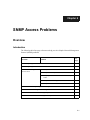
Introduction ............................................................................................................ 6-1
SNMP Reporting Is Not Consistent with the Access Server................................... 6-2
Solution.................................................................................................................... 6-2
SNMP Reporting Is Not Consistent with the MIB ................................................... 6-3
Solution.................................................................................................................... 6-3
Problems Accessing the Access Server ...................................................................... 6-4
Introduction ............................................................................................................ 6-4
Verify SNMP Enabled............................................................................................ 6-4
Verify Community Name Access Information .................................................. 6-5
Verify Operations Enabled for the Community Name..................................... 6-5
Verify Network Configuration ............................................................................. 6-6
Verify Communication to Remote NMS............................................................. 6-6
Access Server Not Responding with the Requested MIB Information ................. 6-7
Solution.................................................................................................................... 6-7
Access Server Not Sending TRAP Messages ..................................................... 6-9
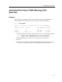
Authentication Failure TRAP Messages Reported................................................. 6-10
Solution.................................................................................................................. 6-10
Authentication Failure TRAP Messages Not Reported......................................... 6-11
Solution.................................................................................................................. 6-11
Chapter 7
3270 Terminal Emulation (TN3270) Access Problems
Overview ........................................................................................................................ 7-1
Introduction ............................................................................................................ 7-1
TN3270 Connection Problems ..................................................................................... 7-2
Introduction ............................................................................................................ 7-2
Verify Display Station Model Configuration ..................................................... 7-2
Verify ASCII Terminal Configuration ................................................................. 7-3
Verify the TN3270 Session Using the Status Line Function ............................. 7-3
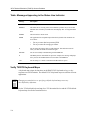
Table: Messages Appearing in the Status Line Indicator ................................. 7-4
Verify TN3270 Keyboard Maps............................................................................ 7-4
Default Keyboard Maps Unsuitable........................................................................... 7-6
Solution.................................................................................................................... 7-6
Telnet Negotiations Problems...................................................................................... 7-7
Solution.................................................................................................................... 7-7
Chapter 8
User Authentication Configuration Problems
Overview ........................................................................................................................ 8-1
Introduction ............................................................................................................ 8-1
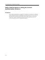
Verify That Devices Are Connected Properly ........................................................... 8-3
Procedure ................................................................................................................ 8-3
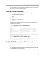
Verify That the Device Is Using the Correct Authentication Protocol................... 8-4
Procedure ................................................................................................................ 8-4
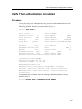
Verify That Authentication Is Enabled....................................................................... 8-5
Procedure ................................................................................................................ 8-5
Verify That Port and Devices Characteristics Match................................................ 8-7
Procedure ................................................................................................................ 8-7
vi
Contents
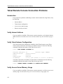
Verify the Access Server and Security Configuration.............................................. 8-8
Procedure ................................................................................................................ 8-8
Verify the User’s Authorization Data ........................................................................ 8-9
Procedure ................................................................................................................ 8-9
Chapter 9
Telnet Remote Console, Connection and Port
Problems
Overview ........................................................................................................................ 9-1
Introduction ............................................................................................................ 9-1
Telnet Remote Console Connection Problems .......................................................... 9-2
Introduction ............................................................................................................ 9-2
Verify Internet Address......................................................................................... 9-2
Verify Telnet Listener Configuration .................................................................. 9-2
Verify Access Server Memory Usage .................................................................. 9-2
Verify Remote Console Port Status ..................................................................... 9-3
Console Port Problems ................................................................................................. 9-4
Solution ................................................................................................................... 9-4
Chapter 10
Terminal and Personal Computer Problems
Overview ...................................................................................................................... 10-1
Introduction .......................................................................................................... 10-1
Port and Device Problems .................................................................................. 10-2
Problems with Interactive Devices ........................................................................... 10-3
Solution ................................................................................................................. 10-3
Device Does Not Respond or Nonsense Characters Appear ........................ 10-3
Characters Not Displayed on the Device ......................................................... 10-4
Command Line Recall Not Working................................................................. 10-6
Terminal Screen Scrolling When MONITOR Command Is Used................. 10-7
Verifying a Port for Hardware Failure ..................................................................... 10-8
Procedure .............................................................................................................. 10-8
PC File Transfer Fails over a LAT Network .......................................................... 10-10
Solution ............................................................................................................... 10-10
PC File Transfer Fails over a SLIP Network...........................................................10-11
Solution ................................................................................................................10-11
PC File Transfer Fails over a Telnet Network ....................................................... 10-12
Solution ............................................................................................................... 10-12
Chapter 11
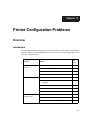
Printer Configuration Problems
Overview .......................................................................................................................11-1
Introduction ...........................................................................................................11-1
Verify the Physical Port Characteristics....................................................................11-2
Procedure ...............................................................................................................11-2
Verify the Port Configuration.....................................................................................11-3
Procedure ...............................................................................................................11-3
vii
Contents
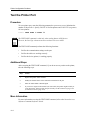
Test the Printer Port .................................................................................................... 11-4
Procedure .............................................................................................................. 11-4
Additional Steps................................................................................................... 11-4
More Information................................................................................................. 11-4
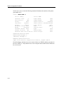
Verify Access Server Information ............................................................................. 11-5
Procedure .............................................................................................................. 11-5
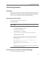
LAT Printing Problems............................................................................................... 11-7
Introduction .......................................................................................................... 11-7
Determine the Point of Failure........................................................................... 11-7
Verify Access Server and Service Node Port Mappings................................. 11-7
Verify the Print Queue......................................................................................... 11-9
Verify LAT Group Codes .................................................................................. 11-12
Determine If Service Is Offered........................................................................ 11-13
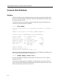
Telnet Printing Problems.......................................................................................... 11-14
Introduction ........................................................................................................ 11-14
Verify Telnet Listener Configuration............................................................... 11-14
Verify Characteristics on Host System............................................................ 11-14
Telnet Printer Not Creating a Newline .................................................................. 11-15
Solution................................................................................................................ 11-15
Chapter 12
Computer Configuration Problems
Overview ...................................................................................................................... 12-1
Introduction .......................................................................................................... 12-1
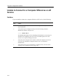
Unable to Connect to a Computer Offered as a LAT Service ............................... 12-2
Solution.................................................................................................................. 12-2
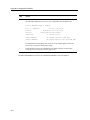
Computer Does Not Respond to LAT Service Connection................................... 12-3
Solution.................................................................................................................. 12-3
Unable to Access a Computer Through a Telnet Listener..................................... 12-5
Solution.................................................................................................................. 12-5
Connected to Telnet Listener but Computer Does Not Respond......................... 12-6
Solution.................................................................................................................. 12-6
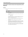
Connection to a Telnet Listener Results in Double Echoes or Double Lines...... 12-8
Solution.................................................................................................................. 12-8
Chapter 13
Modem Configuration Problems
Overview ...................................................................................................................... 13-1
Introduction .......................................................................................................... 13-1
Dial-In Modem Does Not Answer the Telephone .................................................. 13-3
Solution.................................................................................................................. 13-3
Dial-In User Procedure........................................................................................ 13-3
Access Server Manager Procedure .................................................................... 13-3
Dial-In Modem Answers but Carrier Detect Light Is Off...................................... 13-5
Solution.................................................................................................................. 13-5
Dial-in Modem Is Unable to Communicate with the Access Server ................... 13-6
Solution.................................................................................................................. 13-6
Dial-in User Procedure........................................................................................ 13-6
viii
Contents
Access Server Manager Procedure .................................................................... 13-7
Dial-In Modem Disconnects from the Server ......................................................... 13-8
Solution ................................................................................................................. 13-8
Cannot Connect to Dial-Out Modem Offered as a LAT Service .......................... 13-9
Solution ................................................................................................................. 13-9
Connected to LAT Service but Dial-Out Modem Does Not Respond............... 13-10
Solution ............................................................................................................... 13-10
Cannot Connect to Dial-Out Modem Through a Telnet Listener ...................... 13-12
Solution ............................................................................................................... 13-12
Connected to Telnet Listener but Dial-Out Modem Does Not Respond .......... 13-13
Solution ............................................................................................................... 13-13
Cannot Complete Dial-Out to Remote Modem.................................................... 13-15
Solution ............................................................................................................... 13-15
Cannot Complete a Dialback Request Using a Dialer Service ........................... 13-16
Solution ............................................................................................................... 13-16
Chapter 14
IPX Problems
Overview ...................................................................................................................... 14-1
Introduction .......................................................................................................... 14-1
Problems with Dialing In to Access Server Ports ................................................... 14-2
Introduction .......................................................................................................... 14-2
Checking PC Client Status Messages................................................................ 14-2
Checking Cabling Between Port and Modem or Device ............................... 14-2
Checking Configuration of Attached Device................................................... 14-2
Checking Configuration for Login Method ..................................................... 14-2
Monitoring Active Dial-In and Login Attempt ............................................... 14-3
Verifying That PC Client User Knows Login Procedure................................ 14-3
Problems With PPP/IPX Negotiations on the Access Server Port ...................... 14-4
Solution ................................................................................................................. 14-4
Problems with Attaching to a Novell File Server................................................... 14-5
Introduction .......................................................................................................... 14-5
Checking PC Client Status Messages................................................................ 14-5
Checking the Frame Type and Network Address........................................... 14-5
Checking that SAP Services are Available ....................................................... 14-5
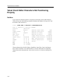
Problems with Relatively Slow File Transfer .......................................................... 14-6
Solution ................................................................................................................. 14-6
Chapter 15
Accounting Problems
Overview ...................................................................................................................... 15-1
Introduction .......................................................................................................... 15-1
Problems with Accounting Log ................................................................................ 15-2
Introduction .......................................................................................................... 15-2
Verify the Log Size ............................................................................................... 15-2
Verify That the Threshold is Appropriate ........................................................ 15-3
Problems with Accounting Console Logging ......................................................... 15-4
ix
Contents
Introduction .......................................................................................................... 15-4
Verify Console Logging Is Enabled ................................................................... 15-4
Verify Server Console Port.................................................................................. 15-5
Chapter 16
Remote Login Problems
Overview ...................................................................................................................... 16-1
In This Chapter..................................................................................................... 16-1
Rlogin Connection Problems ..................................................................................... 16-2
Verify Internet Address .............................................................................................. 16-3
Verify Internet Host Name ................................................................................. 16-3
Verify Domain Name System (DNS) Parameters............................................ 16-4
Verify Communication to Remote Internet Host............................................. 16-4
Verify Access Server Memory Usage ................................................................ 16-5
Verify Rlogin Server Username.......................................................................... 16-7
Rlogin Client Characters Do Not Display on Terminal ......................................... 16-9
Solution.................................................................................................................. 16-9
Procedure .............................................................................................................. 16-9
More Information................................................................................................. 16-9
Rlogin Client Hung ................................................................................................... 16-10
Solution................................................................................................................ 16-10
Rlogin Client Hung After Entering Suspend Input or Suspend IO Sequence . 16-11
Solution................................................................................................................ 16-11
Rlogin Client Editor Characters Not Functioning Properly ............................... 16-12
Solution................................................................................................................ 16-12
Rlogin Terminal Type "Unknown" Insufficient for Some Applications ............ 16-13
Solution................................................................................................................ 16-13
More Information............................................................................................... 16-13
Chapter 17
Directed TFTP Problems
Overview ...................................................................................................................... 17-1
In This Chapter..................................................................................................... 17-1
Missing Access Server IP Address............................................................................ 17-2
Missing Default Gateway IP Address ...................................................................... 17-3
Incorrect Filename....................................................................................................... 17-4
No or Poor Network Connectivity ........................................................................... 17-5
Improperly Configured TFTP Server ....................................................................... 17-6
Directed TFTP Error and Status Messages .............................................................. 17-7
Chapter 18
Messages 000 – 099
Overview ...................................................................................................................... 18-1
Introduction .......................................................................................................... 18-1
Messages................................................................................................................ 18-1
x
Contents
Chapter 19
Messages 200 – 299
Overview ...................................................................................................................... 19-1
Introduction .......................................................................................................... 19-1
Messages ............................................................................................................... 19-1
Chapter 20
Messages 300 – 399
Overview ...................................................................................................................... 20-1
Introduction .......................................................................................................... 20-1
Messages ............................................................................................................... 20-1
Chapter 21
Messages 400 – 499
Overview ...................................................................................................................... 21-1
Introduction .......................................................................................................... 21-1
Messages ............................................................................................................... 21-1
Chapter 22
Messages 500 – 599
Overview ...................................................................................................................... 22-1
Introduction .......................................................................................................... 22-1
Messages ............................................................................................................... 22-1
Chapter 23
Messages 600 – 699
Overview ...................................................................................................................... 23-1
Introduction .......................................................................................................... 23-1
Messages ............................................................................................................... 23-1
Chapter 24
Messages 700 – 799
Overview ...................................................................................................................... 24-1
Introduction .......................................................................................................... 24-1
Messages ............................................................................................................... 24-1
Chapter 25
Messages 800 – 899
Overview ...................................................................................................................... 25-1
Introduction .......................................................................................................... 25-1
Messages ............................................................................................................... 25-1
xi
Contents
Chapter 26
Messages 900 – 999
Overview ...................................................................................................................... 26-1
Introduction .......................................................................................................... 26-1
Messages................................................................................................................ 26-1
Chapter 27
Messages 1000 – 1099
Overview ...................................................................................................................... 27-1
Introduction .......................................................................................................... 27-1
Messages................................................................................................................ 27-1
Chapter 28
Messages 1100 – 1208
Overview ...................................................................................................................... 28-1
Introduction .......................................................................................................... 28-1
Messages................................................................................................................ 28-1
Chapter 29
Service Guidelines
Overview ...................................................................................................................... 29-1
Introduction .......................................................................................................... 29-1
Before You Contact Your Supplier ............................................................................ 29-1
First Steps .............................................................................................................. 29-1
Repackaging the Access Server for Shipping.......................................................... 29-2
What To Do ........................................................................................................... 29-2
Formatting and Sending the Dump File .................................................................. 29-2
Procedure .............................................................................................................. 29-2
xii
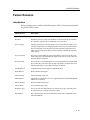
Preface
Overview
Purpose
This guide describes problem-solving tools and procedures for the various network access
servers.
Intended Audience
The Network Access Server Problem Solving Guide is written for the person who
troubleshoots the network access server.
Conventions Used in This Document
Conventions
Familiarizing yourself with the conventions discussed in this section will help you use this
manual effectively.
•
The Return key, which executes all commands, is not shown in command line displays.
•
The Local> prompt, which appears in most examples, is the default access server
prompt. You can change this prompt to something other than Local> with the
SET/DEFINE/CHANGE SERVER PROMPT command.
•
All numbers are in decimal notation unless otherwise noted.
•
All Ethernet addresses are given in hexadecimal notation.
xiii
Preface
Typographical Conventions
The following typographical conventions are used in this manual:
xiv
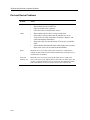
Convention
Description
Special type
Special type in command examples indicates system output or user
input.
UPPERCASE
Uppercase letters in command lines indicate keywords that must
be entered. You can enter them in either uppercase or lowercase.
You can abbreviate command keywords to the first three
characters or to the minimum unique abbreviation.
lowercase italics
Lowercase italics in command syntax indicates variables for which
either the user or the access server supplies a value.
{}
Braces in command syntax indicate that you must choose one of
the enclosed options. (Do not type the braces.)
[]
Brackets in command syntax indicate that the enclosed values are
optional. You can enter one or none. (Do not type the brackets.)
BOLD
Bold type in summaries of characteristics indicates default values.
Ctrl/x
Hold down the Ctrl key; then press the key specified by x. (The
access server displays this key combination as ^x.)
/
A slash indicates related alternate commands or options. For
example, SET/DEFINE/CHANGE PORT refers to the SET PORT,
DEFINE PORT, and CHANGE PORT commands. The slash (/) is
not part of the command syntax.
n
A lowercase italic n indicates a numeric value.
Preface
Associated Documents
Additional Reading
Refer to the following documents for more information:
•
Release Notes — Provides the latest information about the access server. The release
notes are available with the software distribution kit and are stored in the load host
directory with the other software distribution files.
•
Network Access Software Installation Guide (Windows 9x,me,2000 & NT, OpenVMS,
UNIX) — Describes how to install the network access software on your operating
system.
•
Network Access Software Commands Reference Guide — Provides the commands to
operate and manage the access server.
•
Network Access Software Management Guide — Provides the procedures to perform
management tasks for the various access servers.
xv
Chapter 1
Software Installation Problems
Overview
Introduction
The following table lists the steps and page references to help you solve software
installation problems:
Problem
Solution
See
Page
Access Server Software does not
Load Properly
1. Verify the Network Access Server Hardware
1-2
2. Verify the Image Name and Flash RAM
1-2
3. Verify the Load Host
1-3
4. Ensure the Logical MO*$LOAD Is Defined Correctly
on the OpenVMS Host
1-9
5. Ensure the Access Server Software Image File Name Is
Defined Correctly
1-10
Downline Load Request Failure
The section Successful Downline Load Messages shows examples of a downline load of
the software.
NOTE
When you see MO*$LOAD, enter MOM$LOAD for the DECnet Phase IV
software and MOP$LOAD for the DECnet/OSI.
1-1
Software Installation Problems
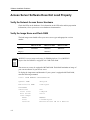
Access Server Software Does Not Load Properly
Verify the Network Access Server Hardware
Check the LEDs on the hardware. For information on the LED codes and site preparation
information, refer to your access server hardware documentation.
Verify the Image Name and Flash RAM
The load image name should reflect your access server type and appropriate version
number.
Software
DECserver 700
DECserver 90M
DECserver 900
WWENG2
MNENG2
WWENG2
Image(s)
NOTE
MNENG3
MNENG3 is a non-compressed image for DS90M platforms. Use of MNENG3
requires that the DS90M is configured with 2 MB Flash RAM.
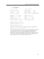
Your access server may be equipped with Flash RAM. Flash RAM maintains an image of
your current software on your access server.
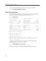
To display the image name and determine if your system is equipped with Flash RAM,
enter the following command:
Local> SHOW MEMORY CONFIGURATION
Dynamic RAM:
4M bytes
Non-Volatile RAM:
128K bytes
FlashRAM:
Installed:
Total size:
Boot block:
Load image:
Name:
Size:
Version:
1-2
Yes
2 Mbytes
Valid
WWENG2
1756988 bytes
Network Access SW Vn.n BLnn-nn
Software Installation Problems
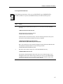
NOTES
If Flash RAM is installed but its boot block is invalid, then the total memory size
will appear as zero.
If your system is equipped with Flash RAM, you can use the INITIALIZE
command to load from either Flash RAM or the load host. If your system is not
equipped with Flash RAM, you can only initialize from the load host. For more
information on initialization, refer to the Network Access Server Management
Guide.
The default INITIALIZE command loads from Flash RAM only if the load image
name displayed with SHOW MEMORY CONFIGURATION matches the software
name shown in the LIST SERVER display.
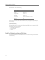
Verify the Load Host
Consult the following information to ensure that your operating system is compatible with
the software. If your operating system is compatible, perform the tasks listed in Verify the
Software Location and File Name through Verify the Load Host Is Available and Service
Is Enabled.
Operating System/Software
Minimum Version Required
DECnet OSI for OpenVMS operating system
Version 5.5
Digital UNIX operating system
Version 1.0
Microsoft Windows 9x,me,2000 operating system
Not applicable
Microsoft Windows NT operating system
Version 3.5.1
OpenVMS VAX operating system
Version 5.0
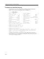
For UNIX systems:
The following generic operating systems are supported. Complete support cannot be
granted on systems where customization has taken place. In addition, some UNIX
implementations, other than those in the following list, may operate successfully, but no
support is implied.
1-3
Software Installation Problems
BOOTP/TFTP - One of the following:
Operating System
Version
SunOS
Release 4.0
Digital UNIX
Version 1.0
IBM AIX
Version 3.1.1
SCO UNIX
System V/386 Release 3.2 V2.0
HP-UX
8.0
Some System V systems, such as HP-UX and SCO, may not support the upline dump of
server memory.
OpenVMS Tailoring:
For OpenVMS Version 5.x systems, the following OpenVMS classes are required for full
functionality of this layered product:
•
•
•
OpenVMS required saveset
Network support
Utilities
Verify the Software Location and File Name
This section explains how to ensure that the access server software image is located in the
correct directory.
1-4
Software Installation Problems
At an OpenVMS load host:
NOTE
In the following instructions, when you see MO*$LOAD, enter MOM$LOAD for
the DECnet Phase IV software and MOP$LOAD for the DECnet/OSI software.
Step
Action
1
Check the logical symbol MO*$LOAD to see if it is defined in the DECSERVER
directory:
$ SHOW LOGICAL MO*$LOAD
MO*$LOAD must be defined to include
SYS$SYSROOT:[DECSERVER].
If MO*$LOAD is not defined correctly, enter the following statement in the system
start-up file on the load host, and then execute the command:
$ DEFINE/SYSTEM/EXEC MO*$LOAD
SYS$SYSROOT:[DECSERVER],other-definitions
Here, other-definitions are any equivalent strings previously defined for MO*$LOAD.
The definition of MO*$LOAD is set in the start-up procedure
SYS$STARTUP:DSV$STARTUP.COM.
2
Determine if the software image file is in the DECSERVER directory:
$ DIRECTORY MO*$LOAD
The directory should contain the name of the access server software image. If you
changed the name of the software image on the access server, be sure MO*$LOAD
contains this image file. If you are unsure of the name of the software image on the
access server, reset the access server to its factory defaults.
1-5
Software Installation Problems
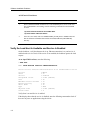
At a UNIX load host, do the following
Verify that all distribution software was installed in the appropriate directory:
# cd /tftpboot (UNIX )
# ls -l
The directory should contain the name of the access server software image and the file:
Release_Notes.txt. If it does not contain the image name, refer to the Network Access
Software Installation Guide for more information. If you have changed the name of the
software image on the access server, be sure the appropriate directory contains this image
file. If you are unsure of the name of the software image on the access server, do the
following:
Step
Action
1
Ensure /tftpboot (UNIX ) contains the default software image for your access server. For
more information on default settings, refer to the Network Access Server Management
Guide.
2
Reset the access server to its factory defaults.
Ensure the Access Server Is Defined on the Load Host
This section explains how to ensure that the access server is defined on the load host.
At an OpenVMS load host:
Ensure your access server is defined in the DSV$CONFIGURE database by entering the
following:
$ @SYS$COMMON:[DECSERVER]DSV$CONFIGURE
DSV$CONFIGURE’s primary function is to configure an access server in the load host
database and enable the service circuit. DSV$CONFIGURE supports both the DECnet
Phase IV and DECnet/OSI software. DSV$CONFIGURE also supports data created by
the procedure DSVCONFIG in earlier versions of the access server software. When you
load the current version of the access server software, DSV$CONFIGURE automatically
converts any DSVCONFIG data to the format of the current version.
If you are downline loading with BOOTP, do not use DSV$CONFIGURE.
NOTE
1-6
Software Installation Problems
For more information on the DSV$CONFIGURE database, refer to the Network Access
Software Installation Guide.
At a UNIX load host:
# /etc/list_Decserver
myds: tc=DS.default: ha=08002BFC0176: ip=192.12.79.6: bf=MNENG2:
gw=192.12.79.3: sm=255.255.255.0
If your access server is missing or contains incorrect information, refer to the Network
Access Software Installation Guide for information on adding an access server.
Ensure the Access Server Is Entered in /etc/bootptab
If you are using Internet Bootstrap Protocol (BOOTP) and Trivial File Transfer Protocol
(TFTP) to downline load the access server software, ensure the /etc/ bootptab file contains
the following information: home directory, Internet address, hardware address, hardware
type, and boot file name. Note that some implementations of the BOOTP protocol require
more information. For more information on the /etc/bootptab file, refer to the Network
Access Software Installation Guide.
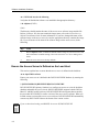
Verify Using Correct Service Circuit
If your load host has more than one Ethernet controller, be sure that you used the correct
service circuit-ID during the DSV$CONFIGURE procedure. If you do not know the load
host service circuit-ID, enter the following NCP command to display active circuits.
At DECnet Phase IV load hosts:
NCP> SHOW ACTIVE CIRCUIT
Active circuit Volatile Summary as of 29-NOV-2000 11:55:31
Circuit State Loopback Adjacent
Name
Routing Node
MFA-0
on
x.xxx
(TSTSIT)
1-7
Software Installation Problems
At DECnet/OSI load hosts:
Step
Action
1
Enter a SHOW SYSTEM command to see if the Net$MOP process exists on the load
host. If NET$MOP is not running, enter the following commands from the SYSTEM
account:
$ @SYS$SYSTEM:STARTUP NETWORK MOP
$ @SYS$STARTUP:DSV$STARTUP
2
If the file is not found, make sure MOP$NAMED_LOAD points to MOP$LOAD and
that the definition of MOP$LOAD includes the SYS$SYSROOT:[DECSERVER]
directory
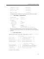
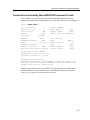
Verify the Load Host Is Available and Service Is Enabled
On the load host, verify that the network is up, Ethernet connection is on, and service is
enabled on the service circuit. If the service is not enabled, the load host ignores the load
request.
At an OpenVMS load host, enter the following:
$ MCR NCP
NCP> SHOW ACTIVE CIRCUIT CHARACTERISTICS
Active Circuit Volatile Characteristics as of 29-NOV-2000 11:55:18
Circuit
State
Service
Designated router
Cost
Maximum routers allowed
Router priority
Hello timer
Type
Adjacent node
Listen timer
=
=
=
=
=
=
=
=
=
=
=
MFA-0
on
enabled
x.xxx (TSTSIT)
10
33
64
15
FDDI
x.xxx (TSTSIT)
4
Verify State is on and Service is enabled.
If the display shows that the service is disabled, enter the following command to check if
there are any users or applications using the circuit:
1-8
Software Installation Problems
NCP> SHOW KNOWN LINKS
If there are no known links active, enter the following commands to enable service circuit
BNA-0. Enabling the circuit disconnects the active links.
NCP>
NCP>
NCP>
NCP>
$
SET CIR BNA-0 STATE OFF
SET CIR BNA-0 SERVICE ENABLED
SET CIR BNA-0 STATE ON
EXIT
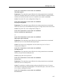
Downline Load Request Failure
Introduction
If you are performing a downline load and you receive an error message on your load host
console (OpenVMS) or in the /usr/spool/mqueue/syslog file (ULTRIX), do the following:
•
Ensure that the logical MO*$LOAD is defined correctly (on OpenVMS load hosts
only).
•
Ensure that the access server software image file name is defined correctly.
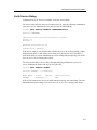
Ensure the Logical MO*$LOAD Is Defined Correctly
on the OpenVMS Host
Problem: The following message appears on the load host console:
%%%%%%%%%%% OPCOM 29-NOV-2000 11:55:18 %%%%%%%%%%%
Message from user DECNET on SATRN
DECnet event 0.7, aborted service request
From node 12.467 (SATRN), 29-NOV-2000 11:55:18
Circuit BNA-0, Line open error, File open error, Load file
%MOM-E-OPENIN, error opening SYS$COMMON:[MOM$SYSTEM]WWENG2.SYS; as input
-RMS-E-FNF, file not found
Node = 13.997 (GEMNI), Ethernet address = 08-00-2B-08-27-57
Explanation: The logical MO*$LOAD is pointing to the MO*$SYSTEM directory, not
the DECSERVER directory.
Action: Define the MO*$LOAD logical to point to the DECSERVER directory. See the
section Verify the Software Location and File Name (page 2-4).
1-9
Software Installation Problems
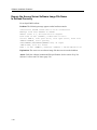
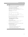
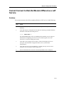
Ensure the Access Server Software Image File Name
Is Defined Correctly
For an OpenVMS load host:
Problem: The following message appears on the load host console:
%%%%%%%%%%% OPCOM 29-NOV-2000 11:55:18 %%%%%%%%%%%
Message from user DECNET on SATRN
DECnet event 0.7, aborted service request
From node 12.467 (SATRN), 29-NOV-2000 11:55:18
Circuit BNA-0, Line open error, File open error, Load file
%MOM-E-OPENIN, error opening
SYS$COMMON:[DECSERVER]WWENG2.SYS; as input
-RMS-E-FNF, file not found
Node = 13.997 (GEMNI), Ethernet address = 08-00-2B-08-27-57
Explanation: The access server software image file does not exist on the load host.
Action: Verify the software location and file specification. See the section Verify the
Software Location and File Name (page 2-4).
1-10
Software Installation Problems
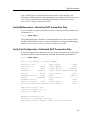
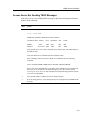
Successful Downline Load Messages
Messages
The following examples show the messages for a successful downline load.
For an OpenVMS load host:
Problem: The following messages appear on the load host console:
%%%%%%%%%%% OPCOM 29-NOV-2000 11:55:18 %%%%%%%%%%%
Message from user DECNET on SATRN
DECnet event 0.3, automatic line service
From node 12.467 (SATRN), 29-NOV-2000 11:55:18
Circuit BNA-0, Load, Requested, Node = 13.997 (MMS1)
File = MOM$SYSTEM_SOFTID:WWENG2, Operating system
Ethernet address = 08-00-2B-08-27-57
%%%%%%%%%%% OPCOM 29-NOV-2000 11:55:18 %%%%%%%%%%%
Message from user DECNET on SATRN
DECnet event 0.3, automatic line service
From node 12.467 (SATRN), 29-NOV-2000 11:55:18
Circuit BNA-0, Load, Successful, Node = 13.997 (MMS1)
File = MOM$SYSTEM_SOFTID:WWENG2, Operating system
Ethernet address = 08-00-2B-08-27-57
Explanation: The access server software is successfully installed. Note that you should
enable event logging for events 0.3 and 0.7 on the DECnet load host. Refer to the DECnet
load host documentation.
Action: No user action is required.
1-11
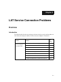
Chapter 2
LAT Service Connection Problems
Overview
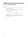
Introduction
The following table lists the steps and page references to help you solve problems that can
occur when you attempt to connect to various resources using the LAT protocol.
Problem
Solution
See
Page
Connection to
resources using the
LAT protocol fails
1. Verify the LAT Service Configuration
2-2
2. Verify the LAT Service Node Software
2-2
3. Verify LAT Group Codes
2-4
4. Verify Access Server Memory Usage
2-6
5. Verify Service Rating
2-9
6. Verify Nodes That Offer the Service
2-10
7. Verify the Connection to a Service
2-10
8. Verify Communications to Another Access Server
2-11
2-1
LAT Service Connection Problems
Connection to Resources Using the LAT Protocol
Fails
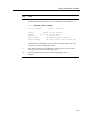
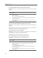
Verify the LAT Service Configuration
This section enables you to determine whether a LAT service is defined and properly
configured on your access server.
On the access server that offers the service, enter the following command. Substitute the
name of the service for Local_Service.
Local> SHOW SERVICE Local_Service CHARACTERISTICS
Service: Local_Service
Identification: Device Connected to a Terminal Server
Ports: 15
Rating: 90
Enabled Characteristics:
Connections, Queuing
Verify that the service is set up on the desired ports and connections are enabled. (If
enabled, Connections appears in the list under Enabled Characteristics.) For more
information on configuring and managing LAT services, refer to the Network Access
Software Management Guide.
Verify the LAT Service Node Software
This section enables you to determine whether the LAT software is running on your LAT
service node. Your service node operating system documentation provides details about
the procedure. For OpenVMS systems, refer to the LAT software documentation that
comes with your operating system.
2-2
LAT Service Connection Problems
At an OpenVMS host (Version 5.4-1 and later):
Ask the system manager of a node that offers the LAT service to invoke the port driver as
follows:
$ RUN SYS$SYSTEM:LATCP
•
If you do not receive the LATCP prompt, LAT software is not running on your
OpenVMS service node.
Action: Run LAT$STARTUP using the following command:
$ @SYS$STARTUP:LAT$STARTUP.COM
•
If you receive the LATCP prompt, verify the status of the LAT protocol by looking at
the Node State and Incoming Connections. Enter the following command at the LATCP
prompt:
LATCP> SHOW NODE
Node Name: EARTH
LAT Protocol Version: 5.2
Node State:OFF
Node Ident: A VAX 6250 Cluster Member
Incoming Connections: Disabled
Outgoing Connections: Enabled
Circuit Timer (msec):
80
Retransmit Limit (msg):
8
Multicast Timer (sec):
30
User Groups:
Service Groups:
Incoming Session Limit: 255
Outgoing Session Limit: 255
Keepalive Timer (sec) : 15
Node Limit (nodes):
100
CPU Rating:
100
80-89
60,125
Service Name
Status
Rating
Identification
EARTH
Available 114 D
A VAX 6250 Cluster Member
GALAXY
Available 114 D
A VAX 6250 Cluster Member
-----------------------------------------------------------------LAT Control Program, Version 5.4-1
-----------------------------------------------------------------LATCP>
If the Node State is OFF, the service node software is not running.
Action: Run LAT$STARTUP using the following command:
$ @SYS$STARTUP:LAT$STARTUP.COM
If Incoming Connections are Disabled, connections are not allowed to the service.
Action: Enable connections using the following command:
LATCP> SET NODE/CONNECTIONS=INCOMING
2-3
LAT Service Connection Problems
To allow both incoming and outgoing connections, use the following command:
LATCP> SET NODE/CONNECTIONS=BOTH
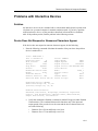
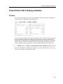
Verify LAT Group Codes
To determine whether a user’s access server port has a group code in common with the
service, enter the following command. Substitute the port number for 1.
Local> SHOW PORT 1
Port 1: Mariellen S.
Server: GEMINI
Character Size:
8
Flow Control:
XON
Parity:
None
Stop Bits:
Dynamic
Input Speed:
9600
Output Speed:
9600
Signal Control:
Disabled
Signal Select: CTS-DSR-RTS-DTR
Access:
Local
Backwards Switch: None
Break:
Local
Forwards Switch:
’
Default Protocol: LAT
Autolink Timer One:10 Two:10
Local Switch:
Name:
Session Limit:
Type:
Default Menu:
Dialer Script:
^^
PORT_1
4
Ansi
None
None
Preferred Service: GALAXY
Authorized Groups: 60, 70
(Current) Groups: 60
Enabled Characteristics:
Autobaud, Autoconnect, Autoprompt, Broadcast, Input Flow
Control, Loss Notification, Message Codes, Output Flow
Control, Verification
If group codes are enabled on the access server port, enter the following command.
Substitute the name of the service for service-name.
Local> SHOW SERVICE service-name
Local -711- Service service-name not known
If the service is not known, verify the group codes that are enabled for the service.
2-4
LAT Service Connection Problems
For services offered by the access server that you are on, enter the following command on
your access server:
Local> SHOW SERVER CHARACTERISTICS
Network Access SW Vn.n for DS716 BLnn ROM Vn.n-n Uptime: 13 16:36:23
Address: 08-00-2B-02-F2-BB Name: MMS1 Number: 65535
Identification: Pubs terminal server
Circuit Timer:
80
Console Port:
1
Inactivity Timer: 30
Keepalive Timer: 20
Multicast Timer: 30
Node Limit:
200
Password Limit:
Prompt:
Queue Limit:
Retransmit Limit:
Session Limit:
Software:
TFTP Host:
3
Local>
100
8
128
WWENG2
None
Service Groups: 60, 70, 80
Enabled Characteristics:
Announcements, Broadcast, Dump, Lock
In this case, the Service Groups are 60, 70, and 80. Ensure that both the Authorized and
Current Groups defined for the port contain at least one of the Service Groups defined on
the access server. For more information on group codes, refer to the Network Access
Server Management Guide.
2-5
LAT Service Connection Problems
For services offered by a service node:
At an OpenVMS host, enter the following commands:
$ RUN SYS$SYSTEM:LATCP
LATCP> SHOW CHARACTERISTICS
Node Name: SATRN
LAT Protocol Version: 5.2
Node State: On
Node Ident: A VAX 6250 Cluster Member
Incoming Connections: Enabled Incoming Session Limit: 255
Outgoing Connections: Enabled Outgoing Session Limit: 255
Circuit Timer (msec): 80 Keepalive Timer (sec): 15
Retransmit Limit (msg): 8 Node Limit (nodes):
100
Multicast Timer (sec): 30 CPU Rating:
100
User Groups:
60, 70
Service Groups: 60, 70
Service Name Status
Rating Identification
EARTH
Available 114 D
A VAX 6250 Cluster Member
GALAXY
Available 114 D
A VAX 6250 Cluster Member
----------------------------------------------------------------LAT Control Program, Version 5.4-1
-----------------------------------------------------------------LATCP>
In this case, the Service Groups are 60 and 70. Ensure that both the Authorized and
Current Groups defined for the port contain at least one of the service node’s Service
Groups. For more information on group codes, refer to the Network Access Server
Management Guide.
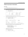
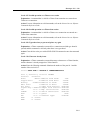
Verify Access Server Memory Usage
The access server has a limited pool of memory. With large networks or many port
sessions, it is possible to run out of memory. When access server memory is filled, the
access server database cannot hold additional information about nodes and services. To
verify that you have a sufficient pool of available memory, enter the following command:
Local> SHOW MEMORY STATUS
2-6
High Pool Size:
892943 bytes
High Pool Used:
563516 bytes
Low Pool Size:
52480 bytes
Low Pool Used:
1940 bytes
LAT Service Connection Problems
Command Pool Size:
20480 bytes
Command Pool Used:
8428 bytes
MOP Pool Size:
4096 bytes
MOP Pool Used:
148 bytes
To display the memory configuration of your system, enter the following command:
Local> SHOW MEMORY CONFIGURATION
Dynamic RAM:
4M bytes
Non-Volatile RAM:
128K bytes
FlashRAM:
Installed:
Total size:
Boot block:
Load image:
Name:
Size:
Version:
Yes
2 Mbytes
Valid
WWENG2
1756988 bytes
Network Access SW Vn.n BLnn-nn
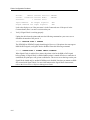
Resource errors indicate the number of times an internal data structure could not be
created due to the lack of system memory. To look at resource errors, enter the following
command:
Local> SHOW SERVER STATUS
Network Access SW Vn.n for DS716 BLnn ROM Vn.n-n Uptime: 13 16:36:23
Address: 08-00-2B-02-F2-BB Name: GEMNI Number: 65535
Cur High Max
Active Ports:
8
10
16 Minutes to Shutdown: N/A
Active Users:
8
10
16 Discarded Nodes:
15
Queue Entries:
0
1
100 Resource Errors:
57
Available Services: 246 253
N/A Port Framing Errors:
0
Local Services:
1
1
20 Port Parity Errors:
0
Reachable Nodes:
195 195
200 Port Overrun Errors:
0
Active Circuits:
Connected Nodes:
Connected Sessions:
% CPU Used:
% Memory Used:
9
7
12
15
80
9
9
20
36
80
32
32
64
100
100
Boot Device: Ethernet: 0
Primary Host:
PEACH
Load Address:AA-00-04-00-46-DC
Dump Address: None Available
Console User:AA-00-04-00-D3-71
Boot Protocol: MOP
Selftest Status: Normal
Software Status: Normal
2-7
LAT Service Connection Problems
If the number of Resource Errors is greater than zero, the access server memory might be
full. Make the following corrections:
Step
Action
1
Adjust the group codes to restrict the least-used nodes from being stored in the access
server database. For information on group codes, refer to the Network Access Server
Management Guide.
2
Adjust the access server node, session, and queue limits to restrict memory usage. For
information on managing an access server, refer to the Network Access Server
Management Guide. Reducing the node limit immediately lessens the number of service
nodes stored in the database and frees some memory. The following command shows
how to set the node limit to 100:
Local> CHANGE SERVER NODE LIMIT 100
3
Verify the ports on the access server for sessions in the Disconnecting or Disconnected
state. Enter the following command. Substitute the port number for 5:
Local> SHOW SESSIONS PORT 5
Port 5: Jack Local Mode Current Session: 1 - Session 1:
Disconnecting Interactive EARTH
Then, perform the following:
a. Find the port sessions that have the status Disconnecting or Disconnected.
b. Disconnect these sessions at the port.
c. If there are no other sessions, log out the same ports.
2-8
LAT Service Connection Problems
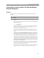
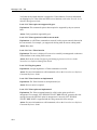
Verify Service Rating
To determine if a LAT service is available, verify the service rating.
For services offered by the access server that you are on, enter the following command on
your access server. Substitute the user’s service name for MONAHON:
Local> SHOW SERVICE MONAHON CHARACTERISTICS
Service: MONAHON
Identification: Internal Production System
Ports: 15
Rating: 0
Enabled Characteristics:
Connections, Queuing
If the service rating is zero, all ports that offer the service are in use and queuing is either
disabled or the queue is full. If the service rating is 90, all ports are in use, but there is
room in the queue. For more information on service ratings and port queuing, refer to the
Network Access Server Management Guide.
For services offered by a service node, enter the following command on your access
server. Substitute the name of the service for GALAXY.
Local> SHOW SERVICE GALAXY
Service GALAXY - 2 Connected
Node Name
GALAXY
Status
Rating
Reachable 0
Identification
VAX
If the service rating is zero, the service node cannot accept any new connections. For more
information on service ratings, refer to the Network Access Server Management Guide.
2-9
LAT Service Connection Problems
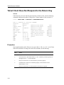
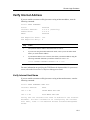
Verify Nodes That Offer the Service
To verify nodes that offer a LAT service, enter the following access server command.
Substitute the user’s service name for MONAHON.
Local> SHOW SERVICE MONAHON
If there are any nodes that offer the service but should not, you need to remove the service.
The following shows how to remove a service (in this case, MONAHON), from an access
server, an OpenVMS host, and an ULTRIX host:
For services offered by a access server:
Local> CLEAR SERVICE MONAHON
Local> PURGE SERVICE MONAHON
For services offered by an OpenVMS service node:
$ RUN SYS$SYSTEM:LATCP
LATCP> DELETE SERVICE MONAHON
Verify the Connection to a Service
To test the connection between the user’s port and the service, enter the following
command at the user’s access server port. Substitute the name of the service for servicename:
Local> TEST SERVICE service-name LOOPBACK EXTERNAL
NOTE
The Multisessions characteristic must be Disabled on your port before you can
enter the TEST SERVICE command.
When the test is completed, the access server displays a report of the test results. If a
connection cannot be made to the service, enter the following command to test the ability
of the service to accept connections:
Local> TEST SERVICE service-name LOOPBACK INTERNAL
For more information on using the TEST SERVICE command, refer to the Network
Access Software Commands Reference Guide.
2-10
LAT Service Connection Problems
Verify Communications to Another Access Server
If you are on a different access server than the one offering the service, verify that the two
access servers can communicate. Enter the following command on the user’s access
server:
Local> TEST LOOP 08-2B-66-10-12-61
NOTE
When you use the TEST LOOP command, enter the Ethernet address of the target
access server.
For more information on using the TEST LOOP command, refer to the Network Access
Software Commands Reference Guide.
2-11
Chapter 3
Telnet Resource Problems
Overview
Introduction
The following table lists steps and page references to help you solve problems that can
occur when you attempt to connect to various resources using the Telnet protocol.
Problem
Solution
See Page
Telnet Resource Connection
Problems Steps
1. Verify Internet Address
3-2
2. Verify Internet Host Name
3-3
3. Verify Domain Name System (DNS) Parameters
3-3
4. Verify Communication to Remote Internet Host
3-3
5. Verify Access Server Memory Usage
3-4
Telnet Client Keyboard Characters Do Not Display Properly
3-5
Telnet Client Characters Do Not Display on Terminal
3-6
Telnet Client Hung
3-8
Telnet Client Hung After Sending AO Character
3-9
Telnet Client Does Not Respond to the Return Key
3-10
Telnet Client Editor Characters Not Functioning Properly
3-12
3-1
Telnet Resource Problems
Telnet Resource Connection Problems
Introduction
If you experience problems connecting to a Telnet resource, verify the following:
•
Internet address
•
Internet host name
•
Domain name system parameters
•
Communication to remote Internet host
•
Network access server memory usage
Verify Internet Address
If you are unable to connect to a Telnet resource using an Internet address, enter the
following command:
Local> SHOW INTERNET
State
Internet Address:
Subnet Mask:
DHCP:
Enabled
0.0.0.0 (Learning)
0.0.0.0
Enabled
TCP Keepalive Timer:120
TCP Keepalive Retry: 8
For more information on specifying the TCP/IP network characteristics for your access
server, refer to the Network Access Software Management Guide.
Step
Action
1
Verify that the Internet address and subnet mask are correct.
2
If you are not using the default subnetwork mask, ensure you set the subnet mask
before you set the Internet address.
3
If your Internet address is set to 0.0.0.0, then define your Internet address using
the following command. Substitute your Internet address for 195.1.1.60:
Local> CHANGE INTERNET ADDRESS 195.1.1.60
3-2
Telnet Resource Problems
Verify Internet Host Name
If you are unable to connect to a Telnet resource using an Internet host name, enter the
following command:
Local> SHOW INTERNET HOST ALL
Internet Address
Name
195.1.1.60
195.1.1.62
SALES.MKTG.FOO.COM
ACCT.MKTG.FOO.COM
Verify that the Internet host name is defined in the Internet database. For more information
on configuring the Internet host name, refer to the Network Access Software Management
Guide.
Verify Domain Name System (DNS) Parameters
If you are unable to connect to a Telnet resource using an Internet host name, enter the
following command:
Local> SHOW INTERNET NAME RESOLUTION CHARACTERISTICS
Domain Name: MKTG.FOO.COM
Resolution Host Limit: 32 Resolution Time Limit: 4
Resolution Mode: Ordered Resolution Retry Limit: 3
Nameservers: (Locally configured)
195.1.1.81
Local NAMED.MKTG.FOO.COM
Nameservers: (Learned)
195.1.1.91
Local
ELF.MKTG.FOO.COM
195.1.1.16
Local
MINE.FOO.COM
195.1.1.82
Local
NAMED.MKTG.FOO.COM
195.1.1.43
Local
WOLF.PERSNL.FOO.COM
Verify that the DNS parameters are set up correctly. For more information on configuring
the access server on a TCP/IP network, refer to the Network Access Software Management
Guide.
Verify Communication to Remote Internet Host
If you are unable to connect to a Telnet resource, determine if the access server can
communicate with the Internet host. Enter the following command. Substitute the Internet
address (or host name) for 195.1.1.60:
Local> PING 195.1.1.60
3-3
Telnet Resource Problems
This command establishes a PING session on the access server port. This session will
continue until the PING succeeds (and sends a verification message) or until the timeout
period of 30 seconds is exceeded. If this command fails, then the Internet host is
unavailable.
NOTE
The PING command is the same as the TEST INTERNET command. For more
information on the PING command, refer to the Network Access Software
Commands Reference Guide.
Verify Access Server Memory Usage
If you experience problems connecting to a Telnet resource, verify access server memory
usage. See the section Verify Access Server Memory Usage (page 2-6).
3-4
Telnet Resource Problems
Telnet Client Keyboard Characters Do Not Display
Properly
Solution
If a keyboard character does not display properly during a Telnet session, enter the
following command. Substitute the number of the port for 1 and the number of the session
for 2:
Local> SHOW PORT 1 SESSION 2 CHARACTERISTICS
Port 1, Session 2, Protocol TELNET
Profile:
Character
Echo:
Remote
Newline From Term:
Toggle Echo: ^E
Newline From Host:
Binary:
Disabled
Newline To Term:
Xmit Size:
8
Newline To Host:
Rcv Size:
8
Input Flow Control:
Signal Req.: Enabled
Output Flow Control:
IP:
+s +f ^Y
Msg. Verification:
SYNCH:
+s -f ^X
Switch Characters:
AYT:
-s -f ^T
Quote:
AO:
-s +f ^O
EOR:
-s -f None
BRK
-s -f None
<CR>
<CRLF>
<CRLF>
<CRLF>
Enabled
Enabled
Enabled
Enabled
None
Verify that the keyboard character is mapped to a Telnet function. For more information
on mapping keys to Telnet client functions, refer to the Network Access Software
Management Guide.
3-5
Telnet Resource Problems
Telnet Client Characters Do Not Display on Terminal
Solution
If characters do not display during a Telnet session, enter the following command.
Substitute the number of the port for 1 and the number of the session for 2:
Local> SHOW PORT 1 SESSION 2 CHARACTERISTICS
Port 1, Session 2, Protocol TELNET
Profile:
Character
Echo:
Locsupr
Newline From Term:
Toggle Echo: ^E
Newline From Host:
Binary:
Disabled
Newline To Term:
Xmit Size:
8
Newline To Host:
Rcv Size:
8
Input Flow Control:
Signal Req.: Enabled
Output Flow Control:
IP:
+s +f ^Y
Msg. Verification:
SYNCH:
+s -f ^X
Switch Characters:
AYT:
-s -f ^T
Quote: None
AO:
-s +f ^O
EOR:
-s -f None
BRK:
-s -f None
<CR>
<CRLF>
<CRLF>
<CRLF>
Enabled
Enabled
Enabled
Enabled
Procedure
Do the following:
3-6
Step
Action
1
Verify that the Echo characteristic is set to Locsupr. (Locsupr causes local
echoing to be suppressed.)
2
If Echo is set to Locsupr, verify the Toggle Echo characteristic to determine its
setting. (In this case, Toggle Echo is mapped to Ctrl/E.)
3
Press the Toggle Echo character.
4
Enter a command line to see if characters are now displayed. If characters still do
not display, see the section Problems with Interactive Devices
(page 10-3) for information on troubleshooting problems with interactive
devices.
Telnet Resource Problems
More Information
For more information on configuring Telnet client session characteristics, refer to the
Network Access Software Management Guide.
3-7
Telnet Resource Problems
Telnet Client Hung
Solution
If your Telnet session appears to be hung, the Telnet remote partner could have abnormally
disconnected the session. Enter the following commands on your access server port:
Local> SEND TELNET AYT
Local> SEND TELNET SYNC
Local> RESUME SESSION
If the connection is down, these commands cause retransmissions to the remote partner. If
the remote partner does not respond within 7 minutes, the connection aborts with a
timeout message.
3-8
Telnet Resource Problems
Telnet Client Hung After Sending AO Character
Solution
If your Telnet session appears to be hung and you previously sent an AO (Abort Output)
character to the host either directly or indirectly, enter the following command on your
access server port to cancel the AO:
Local> SEND TELNET RESUME OUTPUT
When an AO is sent to the host, the access server also sends a timing mark. The host then
returns this timing mark to notify the access server that the AO has been received by the
host. The problem occurs when a host does not return the timing mark to the access server.
NOTE
If the SEND TELNET RESUME OUTPUT command is entered and an AO has not
been sent, the Telnet session is not affected.
3-9
Telnet Resource Problems
Telnet Client Does Not Respond to the Return Key
Solution
If the Return key does not function properly during a Telnet session, enter the following
command. Substitute the number of the port for 1 and the number of the session for 2:
Local> SHOW PORT 1 SESSION 2 CHARACTERISTICS
Port 1, Session 2, Protocol TELNET
Profile:
Character
Echo:
Remote
Newline From Term:
Toggle Echo: ^E
Newline From Host:
Binary:
Disabled
Newline To Term:
Xmit Size:
8
Newline To Host:
Rcv Size:
8
Input Flow Control:
Signal Req.: Enabled
Output Flow Control:
IP:
+s +f ^Y
Msg. Verification:
SYNCH:
+s -f ^X
Switch Characters:
AYT:
-s -f ^T
Quote:
AO:
-s +f ^O
EOR:
-s -f None
BRK:
-s -f None
<CR>
<CRLF>
<CRLF>
<CRLF>
Enabled
Enabled
Enabled
Enabled
None
Procedure
Some implementations of the Telnet server expect either a <CR> or a <LF> as the Telnet
end-of-line terminator. To change the end-of-line terminator, do the following:
3-10
Step
Action
1
Verify the Newline to Host characteristic.
2
Set the Newline to Host characteristic to <CR>. Note that you must type the left
and right arrows (< >) in the command.
3
Retry the connection to see if the Return key functions properly.
4
If the Return key still does not function properly, set the Newline to Host
characteristic to <LF>.
5
Retry the connection to see if the Return key functions as expected.
Telnet Resource Problems
More Information
For more information on configuring Telnet client session characteristics, refer to the
Network Access Software Management Guide.
3-11
Telnet Resource Problems
Telnet Client Editor Characters Not Functioning
Properly
Solution
If you experience unusual responses to keystrokes when using various editors during a
Telnet session, enter the following command. Substitute the number of the port for 1 and
the number of the session for 2:
Local> SHOW PORT 1 SESSION 2 CHARACTERISTICS
Port 1, Session
Profile:
Echo:
Toggle Echo:
Binary:
Xmit Size:
Rcv Size:
Signal Req.:
IP:
SYNCH:
AYT:
AO:
EOR:
BRK:
2, Protocol TELNET
Character
Remote
Newline From Term:
^E
Newline From Host:
Duplex
Newline To Term:
8
Newline To Host:
8
Input Flow Control:
Disabled
Output Flow Control:
+s +f ^Y
Msg. Verification:
+s -f ^X
Switch Characters:
-s -f ^T
Quote:
-s +f ^O
-s -f None
-s -f None
<CR>
<CRLF>
<CRLF>
<CRLF>
Disabled
Disabled
Enabled
Enabled
None
The port characteristics (Profile, Binary, Signal Req., Input Flow Control, and Output
Flow Control) should be set as indicated above. For more information on configuring
Telnet client session characteristics, refer to the Network Access Software Management
Guide.
3-12
Chapter 4
SLIP/PPP Problems
Overview
Introduction
This chapter discusses troubleshooting procedures for problems that might occur when
you attempt to connect to various resources using the SLIP, SLIP compression (CSLIP), or
PPP protocols. For similar conditions, SLIP and PPP share many of the same error
messages. As a result, a SLIP message may follow a PPP command.
The following table lists the steps and page references to help you solve problems that can
occur when you attempt to connect to various resources using the SLIP/PPP protocols.
Problem
SLIP
Connection
Problems
Solution
See
Page
1.
Verify SLIP/CSLIP Enabled
4-3
2.
Verify Access Server Memory Usage
4-3
3.
Verify Internet Address
4-3
4.
Verify SLIP Host Address
4-4
5.
Verify Maximum Transmission Unit (MTU)
4-4
6.
Verify Multisessions - Interactive SLIP Connection Only
4-5
7.
Verify Port Configuration - Dedicated SLIP Connection Only
4-5
SLIP Session Losing Send Packets
4-7
SLIP Session Not Receiving Input
4-8
SLIP Session Will Not Learn the PC Internet Address
4-9
4-1
SLIP/PPP Problems
Problem
4-2
Solution
See
Page
SLIP Session Starts, Then Freezes
4-10
PPP Connection Problems
4-11
SLIP/PPP Problems
SLIP Connection Problems
Introduction
You can establish only one datalink session (either SLIP or PPP) on a port at a given time.
If you have a session established, another session is not permitted. In addition, SLIP and
PPP use the same IP address for a port. You can clear this address only when another
datalink session is not using it.
Verify SLIP/CSLIP Enabled
To determine if SLIP is enabled on the access server port, enter the following command.
Substitute the port number for 1:
Local> SHOW PORT 1
NOTES
Header Compression should be enabled. Use the SHOW PORT SLIP command to
verify that it is enabled.
If enabled, SLIP is displayed in the list under Enabled Characteristics. For more
information on configuring and managing SLIP ports, refer to the Network Access
Software Management Guide.
If you have SLIP/CSLIP enabled, verify that all systems (both ends) have
SLIP/CSLIP enabled; otherwise, significant system degradation will occur.
Verify Access Server Memory Usage
If you experience connection problems using the SLIP protocol, verify the access server.
See the section Verify Access Server Memory Usage (page 2-6).
Verify Internet Address
If you are unable to connect using the SLIP protocol, verify that the Internet address has
been set on the access server. See the section Verify Internet Address (page 3-2).
4-3
SLIP/PPP Problems
Verify SLIP Host Address
If you are unable to connect using the SLIP protocol, enter the following command.
Substitute the number of the port for 1:
Local> SHOW PORT 1 SLIP
Port 1: Development
Server: MMS
Host Address:
83.62.18.102
Header Compression: Disabled
MTU:
1006
Compression States
16
Verify that the SLIP Host Address is defined and valid. The Internet address for the SLIP
host must be unique on the subnet and have the same subnet identifier as the access server.
For example, if the access server Internet address is 83.62.18.101 and the subnet mask is
255.255.255.0, the subnet identifier is 83.62.18.0. Therefore, the SLIP host address must
be 83.62.18.nn, where nn is any number between 1 and 254, except 101 (access server
Internet address).
For more information on configuring and managing SLIP ports, refer to the Network
Access Software Management Guide.
Verify Maximum Transmission Unit (MTU)
To determine the MTU size, enter the following command. Substitute the number of the
port for 1:
Local> SHOW PORT 1 SLIP
Port 1: Development
Server: MMS
Host Address:
83.62.18.102
Header Compression: Disabled
NOTE
MTU:
1006
Compression States
16
Many implementations use an MTU of 296 with CSLIP.
The MTU characteristic allows access server compatibility with SLIP host
implementations that have fixed MTU values other than 1006 bytes. The TCP maximum
segment size (MSS) announced by the SLIP host at the time of a TCP connection is
normally based on the MTU of the network connection.
4-4
SLIP/PPP Problems
If the TCP MSS given by the SLIP host exceeds the MTU on the SLIP line, poor
performance, failed connections, and fragmentation occur. Adjust the MTU on the access
server. For more information on configuring and managing SLIP ports, refer to the
Network Access Software Management Guide.
Verify Multisessions - Interactive SLIP Connection Only
If you are unable to connect to a SLIP host, enter the following command. Substitute the
port number for 1:
Local> SHOW PORT 1
Verify that Multisessions is Disabled. (If Disabled, Multisessions does not appear in the
list under Enabled Characteristics.) For more information on configuring and managing
SLIP ports, refer to the Network Access Software Management Guide.
Verify Port Configuration - Dedicated SLIP Connection Only
If you are having problems connecting to a device, such as a computer or PC configured as
a dedicated SLIP host, enter the following command. Substitute the port number for 1:
Local> SHOW PORT 1
Port 1: Development S. Server: GEMINI
Character Size:
Flow Control:
Parity:
Stop Bits:
8
None
None
Dynamic
Access:
Local
Backwards Switch:
None
Break:
Disabled
Forwards Switch:
‘
Default Protocol:
SLIP
Autolink Timer One:10 Two:10
Input Speed:
9600
Output Speed:
9600
Signal Control:
Disabled
Signal Select:CTS-DSR-RTS-DTR
Local Switch:
Name:
Session Limit:
Type:
Default Menu:
Dialer Script:
None
PORT_1
4
Ansi
None
None
Dedicated Service: SLIP
Authorized Groups: 60, 70
(Current) Groups: 60
Enabled Characteristics:
Autoconnect, Broadcast, Failover,
Loss Notification, Message Codes, SLIP, Verification
4-5
SLIP/PPP Problems
•
Verify that Autobaud is Disabled. (If Disabled, Autobaud does not appear in the list
under Enabled Characteristics.)
•
Verify that Input Speed and Output Speed are consistent with that of the device.
•
Verify that Default Protocol is set to SLIP.
•
Verify that Dedicated Service is set to SLIP.
•
Verify that Access is either Local or Dynamic.
For more information on configuring and managing SLIP ports, refer to the Network
Access Software Management Guide.
4-6
SLIP/PPP Problems
SLIP Session Losing Send Packets
Solution
If your SLIP session appears to be dropping send packets, enter the following command.
Substitute the number of the port for 1:
Local> SHOW PORT 1 SLIP COUNTERS
Port 1: Development Server: MMS
Connect Time: 7 23:00:40
Bytes Received:
106 Bytes Sent:
560
Packets Received:
200 Packets Sent:
150
Receive Packets Lost: 100 Send Packets Lost: 25
Send Packets Queued: 0
Procedure
Verify the ratio of Send Packets Lost to Packets Sent. If this ratio is high, do the following:
Step
Action
1
Adjust the PC software TCP maximum segment size (MSS) and/or the PC software
TCP window size.
2
Increase the baud rate on both the access server and the PC.
3
Increase the MTU on both the access server and the attached device.
4
Verify the MSS on the SLIP host relative to the access server MTU. See the section
Verify Maximum Transmission Unit (MTU), on page 4-4.
More Information
For more information on configuring and managing SLIP ports, refer to the Network
Access Software Management Guide.
4-7
SLIP/PPP Problems
SLIP Session Not Receiving Input
Solution
If your SLIP session will not transmit or receive, check that the port’s speed and the PC’s
communication port speed match.
If your SLIP session seems to transmit but is not receiving input, enter the following
command. Substitute the number of the port for 1:
Local> SHOW PORT 1 SLIP
Port 1: Development
Server: MMS
Host Address:
83.62.18.102
Header Compression: Disabled
MTU:
1006
Compression States 16
Verify that the access server port’s host address and the PC Internet address are the same.
For more information on configuring and managing SLIP ports, refer to the Network
Access Software Management Guide.
4-8
SLIP/PPP Problems
SLIP Session Will Not Learn the PC Internet Address
Solution
If the access server port is unable to learn the SLIP host address, verify that the Internet
address for the SLIP host has the same subnet identifier as the access server and is unique.
See the section Verify SLIP Host Address (page 4-4).
4-9
SLIP/PPP Problems
SLIP Session Starts, Then Freezes
Solution
If your SLIP session starts, then freezes, do the following:
•
Verify that there are no devices between the PC and the access server using
XON/XOFF flow control.
•
Verify that the PC is not running CSLIP. If you are using CSLIP, both the access server
and the attached device must have CSLIP enabled.
For more information on configuring and managing SLIP ports, refer to the Network
Access Software Management Guide.
4-10
SLIP/PPP Problems
PPP Connection Problems
Introduction
PPP connection problems can be traced to incomplete PPP negotiations between peers or
to network traffic not being passed. The following sections discuss some symptoms and
possible solutions.
Attempts to Use Multiple Sessions on a Port
You can establish only one datalink session (either SLIP or PPP) on a port at a given time.
If you have a session established, another session is not permitted. In addition, SLIP and
PPP use the same IP address for a port. This address can be cleared only when it is not in
use by another datalink session.
Verify Access Server Memory Usage
If you experience connection problems using the PPP protocol, verify access server
memory usage.
PPP LCP Connections Fail
Check the following:
•
Verify that a normal interactive login can be done using the same modems and a
terminal emulator running on the client.
•
LCP must be in the OPEN state. To determine the state, enter the SHOW PORT LCP
STATUS command and check the State field.
•
The port characteristic LCP must be enabled on the port. To determine if LCP is
enabled, enter the SHOW PORT LCP CHARACTERISTICS command and check the
LCP field.
•
With LCP Passive Open enabled for a port, the access server never initiates LCP
negotiations. The host device must initiate negotiations. Consider setting LCP Passive
Open to DISABLED.
4-11
SLIP/PPP Problems
•
Verify that flow control is functioning properly.
By default, the low 32 characters of the ASCII set are not sent across an asynchronous
line in the clear. They are "byte-stuffed." LCP allows the user to specify that some of
these characters are sent in the clear. If this is done, then possibly a character that is
being sent in the clear is being acted upon by the underlying hardware or software. For
example, XON/XOFF may be sent in the clear as data, when at the same time the
hardware is using XON/XOFF flow control.
•
If LCP PAP or CHAP authentication is enabled, verify that the PC supports PAP or
CHAP and has the correct password. The password must match the server login
password. If USERNAME is specified for LCP authentication, the username and
password are used for authentication and must match a valid username and password
pair at the proper authentication server. Both the username and the password are casesensitive.
•
If the attached device wants the access server to authenticate itself, problems may
occur. The access server does not support this. Turn off authentication in the attached
device.
PPP IPCP (TCP/IP) Connections Fail
Check the following:
•
For IP, IPCP must be in the OPEN state. To determine the state, enter the SHOW PORT
IPCP STATUS command and check the State field.
•
The port characteristic IPCP must be enabled on the port. To determine if IPCP is
enabled, enter the SHOW PORT IPCP CHARACTERISTICS command and check the
IPCP field.
•
If the IPCP COMPRESSION parameter is enabled for a port, then TCP/IP compression
must be in effect on the host system also.
PPP ATCP (AppleTalk) Connections Fail
Check the following:
4-12
•
For AppleTalk, ATCP must be in the OPEN state. To determine the state, enter the
SHOW PORT ATCP STATUS command and check the State field.
•
AppleTalk must be enabled on the access server or ATCP does not reach the OPEN
state. Refer to Chapter 5 for more information on troubleshooting AppleTalk problems.
•
The port characteristic ATCP must be enabled. To determine if ATCP is enabled, enter
the SHOW PORT ATCP CHARACTERISTICS command and check the ATCP field.
SLIP/PPP Problems
•
ATCP always executes a PASSIVE open, which in effect forces the attached device to
initiate negotiations.
•
If the access server cannot acquire an AppleTalk address from the AppleTalk cache
manager, ATCP cannot reach the OPEN state.
•
The peer's MTU may be too low. To determine the size of the MRU, enter the SHOW
PORT LCP STATUS command and check the MRU field.
The peer may negotiate the use of an MRU other than the default of 1500 bytes. If this is
the case, the access server sets the port's MTU to match. AppleTalk does not support
datagram fragmentation. If the peer's MRU is smaller than the size of the AppleTalk
packet, the packet is dropped. AppleTalk packets can be up to 600 bytes in size.
PPP IPXCP (Novell) Connections Fail
Check the following:
•
For Novell, IPXCP must be in the OPEN state. To determine the state, enter the SHOW
PORT IPXCP STATUS command and check the State field.
•
Novell NetWare must be enabled on the access server or IPXCP does not reach the
OPEN state. Refer to Chapter 14 for more information on troubleshooting IPX
problems.
•
The port characteristic IPXCP must be enabled. To determine if IPXCP is enabled,
enter the SHOW PORT IPXCP CHARACTERISTICS command and check the IPXCP
field.
If problems with PPP/IPX negotiations remain after successful dial-in and login, verify the
following:
•
Check the PC client status messages.
•
Check to see if the port is configured for PPP/IPX.
•
Monitor the PPP/IPX negotiations.
•
Check to see if PPP/PAP password authentication is enabled.
Checking PC Client Status Messages
Check the remote node access software used on the PC client when connecting. It may
offer status messages giving some indication as to what part of the process is failing.
4-13
SLIP/PPP Problems
Checking the Port’s PPP/IPX Configuration
Type SHOW PORT n LCP CHARACTERISTICS and SHOW PORT n IPXCP
CHARACTERISTICS to check the current PPP characteristics and verify that both LCP
and IPXCP are enabled. Substitute the number of the port for ‘n’.
Monitoring PPP/IPX Negotiations for Failure Reason
If possible, you may want to monitor the port as the PPP negotiations occur after modem
login. Type MONITOR PORT n LCP STATUS or MONITOR PORT n IPXCP STATUS.
If PPP is failing, note the failure reason code in the display. Descriptions of these codes are
in the section Failure Reasons.
Checking to See if PPP/PAP Password Authentication is Enabled
Type SHOW PORT n LCP CHARACTERISTICS. If authentication is enabled, make sure
the PC client user configures the password for the remote node access software in use.
Note that verification of password is case sensitive.
Refer to Chapter 14 for further information on IPX problems.
4-14
SLIP/PPP Problems
Failure Reasons
Introduction
When you display status, a failure reason field appears. Table: Failure Reasons describes
the possible failure reasons.
Failure Reason
Description
None
No failure reason.
Resources
Insufficient resources. This error condition occurs when setting up an address
for a port fails, typically due to insufficient system resources.
Not converging
Option negotiations are not converging. The server and attached client are not
currently in agreement as to changing optional values away from their defaults.
This error typically occurs when the client has proposed an option the server
either wishes to NAK (providing a counter-proposal) or REJect the requested
client options.
No peer response
The peer is not responding to protocol negotiations. This can occur due to the
client going away or being temporarily stopped. This can also occur if there is a
problem with the connection.
Rx invalid data
The server has received what appears to be an invalid packet from the attached
device. This may occur if the client is using a proprietary extension (that is, an
undefined PPP code) or a new PPP code has been defined.
Unauthenticated
An attached device fails to properly authenticate itself.
IPCP disabled
IPCP is disabled on this port.
ATCP disabled
ATCP is disabled on this port.
ATK disabled
AppleTalk is not enabled on the server. AppleTalk must be defined ENABLED
and the server rebooted.
IPXCP disabled
IPXCP is disabled on this port.
LCP disabled
LCP is disabled on this port.
Stopped by peer
The server side of the PPP link has been stopped by the peer. Typically, this is
the result of the peer sending a Terminate request.
IPX disabled
IPX is not enabled on the server. IPX must be either SET or DEFINED (with
reboot) ENABLED.
4-15
SLIP/PPP Problems
Failure Reason
Description
Peer address bad
This occurs if the address negotiated for the peer is invalid. For IPXCP, this
error occurs if the address is already in use or if the client agreed to use the
server’s internal network but did not negotiate a unique node address.
No net address
Indicates the server does not have a net/node address for itself. Verify that the
server’s internal IPX network has been set.
4-16
Chapter 5
AppleTalk Access Problems
Overview
Introduction
The following table lists the steps and page references to help you solve problems that can
occur when using the AppleTalk functionality on the access server.
Problem
Solution
See
Page
Problems with Hosts
Attached to Access
Server Ports
1.
Verify AppleTalk Is Enabled
5-3
2.
Verify AppleTalk State Is Up
5-3
3.
Verify AppleTalk Address Is Within the
Network Range
5-4
4.
Verify Cache Size Is Correct
5-4
5.
Verify Access Server Is Visible on the
Network
5-5
6.
Verify Attached Host Software
5-5
7. Verify PPP and ATCP Are Enabled
5-5
8.
Verify Attached Device Is an End Node
5-6
9.
Verify Port Configuration - Dedicated PPP
Connection Only
5-6
1.
Verify Unique AppleTalk Addresses
5-7
Performance Problems
5-1
AppleTalk Access Problems
2.
Verify Protocol Retransmission Timeouts
5-7
3.
AppleTalk Gateway Route
5-8
Problems with attached host connections running AppleTalk are not discussed here, but
are covered in Chapter 4.
5-2
AppleTalk Access Problems
Problems with Hosts Attached to Access Server
Ports
Introduction
If you experience problems creating an AppleTalk connection from an attached host or
polling the access server from a network management station (NMS), verify the
following:
•
AppleTalk is enabled on the access server.
•
AppleTalk state is Up.
•
AppleTalk address is within the network range.
•
Cache size is nonzero.
•
Access server is visible on the network.
•
Attached host is running AppleTalk over PPP.
•
PPP and ATCP are enabled.
•
Attached host is configured as end node.
•
Port configuration — dedicated PPP connection only.
Verify AppleTalk Is Enabled
To determine if AppleTalk is enabled on the access server, enter the following command:
Local> SHOW APPLETALK
If AppleTalk is not enabled, enter the following command:
Local> SET APPLETALK ENABLED
Verify AppleTalk State Is Up
In order to communicate using AppleTalk, the State field must be Up. To determine the
status of the State field, enter the following command:
Local> SHOW APPLETALK STATUS
If State is Off, the access server could not acquire an AppleTalk address for itself.
5-3
AppleTalk Access Problems
Verify AppleTalk Address Is Within the Network Range
It is possible that the AppleTalk address is outside the network range. This situation can
occur momentarily while the access server is booting and is considered normal. However,
if this situation persists for more than a minute after initialization, then the problem could
be caused by one of the following reasons:
•
All valid addresses in the network range are in use. To eliminate this problem, increase
the AppleTalk network range to make more addresses available, or if there are other
access servers on the network using AppleTalk, reduce their defined AppleTalk cache
size.
•
A rogue AppleTalk router is advertising an incorrect network range. To eliminate this
problem, verify the network range advertised by all AppleTalk routers on the network.
Verify Cache Size Is Correct
The access server caches a number of AppleTalk addresses to be given to attached hosts at
connection time. This number is specified using the DEFINE APPLETALK CACHE
SIZE command. The dynamic cache size is shown in the SHOW APPLETALK STATUS
display.
The dynamic cache size is always less than or equal to the defined value and fluctuates as
connections are created or torn down. However, in the steady state, the two values should
match.
If the dynamic cache size gets too small, or reaches zero, host connection attempts could
fail. Therefore, a dynamic cache size that is persistently lower than the defined value is a
problem. The following are possible causes and solutions:
•
Access server memory usage is too high so cache entries cannot be created. If this
occurs, the access server sets the Last Error field in the SHOW APPLETALK STATUS
display as follows:
Could not create AppleTalk cache entry, insufficient
resources
Verify the access server memory usage. See the section Verify Access Server Memory
Usage (page 2-6).
5-4
AppleTalk Access Problems
•
Access server could not acquire addresses in the network range. If this occurs, the
access server sets the Last Error field in the SHOW APPLETALK STATUS display as
follows:
Attempt to acquire an AppleTalk address for cache failed
Refer to the section Verify AppleTalk Address Is Within the Network Range for reasons
why this can occur.
Verify Access Server Is Visible on the Network
When AppleTalk is enabled, the access server attempts to register its Name (specified by
Name in SHOW SERVER CHARACTERISTICS display) using the Name Binding
Protocol (NBP). This registration occurs when the access server boots or when an
AppleTalk router comes up on a network where no router was previously available (for
example, all routers went down and then came back up). If the access server Name is in
use on the network, the access server falls back to registering its default Name, which is
LAT_"ethernet address". The access server sets the Last Error Field in the SHOW
APPLETALK STATUS display as follows:
Duplicate AppleTalk server name on network - trying
LAT_ethernet
If the access server finds a duplicate name while registering its default name, it leaves its
name registered anyway and displays the following message in the Last Error Field on the
SHOW APPLETALK STATUS display:
Registering duplicate AppleTalk server name on network
Verify Attached Host Software
To create connections, the attached hosts must be running AppleTalk over PPP (ATCP).
Verify this on the attached host.
Verify PPP and ATCP Are Enabled
To determine if PPP is enabled on the access server port, enter the following command.
Substitute the port number for 1:
Local> SHOW PORT 1
If Enabled, PPP is displayed in the list under Enabled Characteristics. For more
information on configuring and managing PPP ports, refer to the Network Access Software
Management Guide.
5-5
AppleTalk Access Problems
To determine if ATCP is enabled on the access server port, enter the following command.
Substitute the port number for 1:
Local> SHOW PORT 1 ATCP
The ATCP field should be set to Enabled. For more information on configuring and
managing ATCP ports, refer to the Network Access Software Management Guide.
Verify Attached Device Is an End Node
The access server provides connections for devices acting as AppleTalk end nodes.
Connections to routers or other access servers using asynchronous links are not supported.
Verify that the attached host is acting as an AppleTalk end node.
Verify Port Configuration - Dedicated PPP Connection Only
If you are having trouble connecting an attached host that is configured as a dedicated PPP
host, enter the following command. Substitute the port number for 1:
Local> SHOW PORT 1
•
Verify that Autobaud is Disabled (if Disabled, Autobaud does not appear in the list
under Enabled Characteristics).
•
Verify that Input Speed and Output Speed are consistent with that of the device.
•
Verify that Default Protocol is set to PPP.
•
Verify that Access is either Local or Dynamic.
For more information on configuring and managing PPP ports, refer to the Network
Access Software Management Guide.
5-6
AppleTalk Access Problems
Performance Problems
Introduction
It is possible that AppleTalk connections can be established, but performance is sluggish
or unreliable. Some symptoms of this are long file transfer times or inability to access
some services on the network. These problems are usually due to the slower data rates of
remote connections. We recommend that remote AppleTalk connections by means of the
access server run at rates of 9600 baud or higher. Aside from this solution of running at
higher data rates (that is, faster modems and/or modems using compression), factors
discussed in the next two sections should be checked.
Verify Unique AppleTalk Addresses
It is essential that all nodes running AppleTalk on the network have unique AppleTalk
addresses. If two nodes incorrectly acquire the same AppleTalk address (for example, due
to temporary network partition), then many problems can follow, some of which may
appear as performance problems. Using a management tool, verify that no other device is
using the same address as your connection.
It is also essential that all AppleTalk networks connected into an Internet have unique,
nonoverlapping network ranges. If this requirement is broken, traffic will be routed
incorrectly. This problem may surface as an inability to access services on another
network or as performance degradation. Verify that all AppleTalk networks that are
internetworked have unique network ranges.
Verify Protocol Retransmission Timeouts
Verify that the reliable transport protocols on the attached hosts and network servers are
estimating round-trip time when determining retransmission timeouts. If the transport
protocols use fixed timeouts, then they are likely to retransmit too soon when one link in
the connection is slow. This causes redundant retransmission, which wastes buffer space
and bandwidth, exacerbating the problem on the slow link. If the retransmission timeout is
set using a round-trip time estimate, these redundant retransmissions can be avoided,
resulting in much improved performance.
5-7
AppleTalk Access Problems
AppleTalk Gateway Route
Solution
If the AppleTalk node to which you wish to connect is outside your local LAN, there may
be a problem connecting to a router between the LANs. The access server keeps track of a
default AppleTalk router to which it directs all attached host-generated AppleTalk traffic
that is destined off the local network. The entry for this router is in the SHOW
APPLETALK ROUTING display with the destination field specifying "<default>", as
follows:
Local> SHOW AppleTalk ROUTES
AppleTalk Routes
Destination
Next Hop
12344-12350
<default>
12349.223
12348.144
12346.132
12347.1
12345.132
12345.132
Server:LAT_08002B24F24F
Status
Interface
Up
Up
Up
Up
Ethernet
Ethernet
Asynch7
Asynch3
Seconds since
Last Validated
159
20
29
116
If a default routing entry does not exist, the following lists possible causes and solutions:
•
There is no active AppleTalk router on the network. Check the AppleTalk routers on
the network.
•
The access server could not create a routing entry for the default router. This occurs if
there is a memory usage problem. Check the Error field in the SHOW APPLE TALK
STATUS display. Verify the access server memory usage. See the section Verify Access
Server Memory Usage (page 2-6).
If this default routing entry does exist, but attached hosts still cannot send traffic off the
local network, the following lists possible causes and solutions:
5-8
•
The router in question is not functioning. Check the status of the router.
•
The attached hosts have acquired addresses in the start-up range and all, or almost all,
valid addresses in the network range are being used. See the section Verify AppleTalk
Address Is Within the Network Range (page 5-4).
Chapter 6
SNMP Access Problems
Overview
Introduction
The following table lists page references to help you solve Simple Network Management
Protocol (SNMP) problems.
Problem
Solution
See
Page
SNMP Reporting Is Not Consistent with the access server
6-2
SNMP Reporting Is Not Consistent with the MIB
6-3
Problems Accessing the
access server
1.
Verify SNMP Enabled
6-4
2.
Verify Community Name Access Information
6-5
3.
Verify Operations Enabled for the Community
Name
6-5
4.
Verify Network Configuration
6-6
5.
Verify Communication to Remote NMS
6-6
Access server Not Responding with the Requested MIB Information
6-7
Access server Not Sending TRAP Messages
6-9
Authentication Failure TRAP Messages Reported
6-10
Authentication Failure TRAP Messages Not Reported
6-11
6-1
SNMP Access Problems
SNMP Reporting Is Not Consistent with the Access
Server
Solution
If the data reported by SNMP does not appear to be consistent with that reported by the
access server user interface, verify that the information in question is correct. For more
information, refer to the Network Access Software Management Guide, the release notes,
and the management information bases (MIBs).
6-2
SNMP Access Problems
SNMP Reporting Is Not Consistent with the MIB
Solution
If the data reported by SNMP does not appear to be consistent with that reported by the
MIB, verify that the information in question is correct. For more information, refer to the
Network Access Software Management Guide and the release notes.
6-3
SNMP Access Problems
Problems Accessing the Access Server
Introduction
If you experience problems with your access server responding to SNMP requests from a
network management station (NMS), verify the following:
•
SNMP enabled
•
Community name access information
•
Operations enabled for the community name
•
Network configuration
•
Communication to a remote NMS
Verify SNMP Enabled
To determine if SNMP is enabled on the access server, enter the following command:
Local> SHOW SNMP
SNMP State:
Enabled
Authentication Failure: Enabled
Community Name
Address
GET GETNEXT SET TRAP
PUBLIC
ANY
ENA ENA
DIS DIS
Verify that SNMP State is Enabled. If it is not, enter the following command:
Local> CHANGE SNMP ENABLED
If this command fails, do the following:
6-4
Step
Action
1
Verify that the Internet address has been set on the access server. See the section
Verify Internet Address (page 3-2).
2
Verify the access server memory usage. See the section Verify Access Server Memory
Usage (page 2-6).
SNMP Access Problems
Verify Community Name Access Information
In order to communicate using SNMP, the user on the NMS must know the community
name on the access server. To determine which community names exist on an access
server, enter the following command:
Local> SHOW SNMP
SNMP State:
Enabled
Authentication Failure:
Enabled
Community Name
Address
GET GETNEXT SET TRAP
PUBLIC
SECRET
ANY
60.10.12.61
ENA ENA
ENA ENA
DIS DIS
ENA ENA
Verify that the access server allows either:
•
Any NMS to access the community name
•
A specific NMS to access the community name
If the Address field is set to ANY, any NMS can access that community name. If the
Address field contains an NMS IP address, only that NMS can access that community
name. For more information on configuring the access server for SNMP access, refer to
the Network Access Software Management Guide.
Verify Operations Enabled for the Community Name
SNMP access to the access server is configured by SNMP communities. To determine
what operations are enabled for the community name, enter the following command:
Local> SHOW SNMP
SNMP State:
Enabled
Authentication Failure:
Enabled
Community Name
Address
GET GETNEXT SET TRAP
PUBLIC
SECRET
ANY
60.10.12.61
DIS DIS
ENA ENA
DIS DIS
ENA ENA
If the required operations are Disabled, enter the following commands. Substitute the
community name for Public:
Local> CHANGE SNMP COMMUNITY "Public" GET ENABLED
Local> CHANGE SNMP COMMUNITY "Public" GETNEXT ENABLED
Local> CHANGE SNMP COMMUNITY "Public" SET ENABLED
For more information on configuring the access server for SNMP access, refer to the
Network Access Software Management Guide.
6-5
SNMP Access Problems
Verify Network Configuration
If the access server and network management station (NMS) are on different subnetworks,
verify that there are one or more routers connecting the two subnetworks.
If not, reconfigure the network or move either the access server or the NMS so that they
are on the same network.
If one or more routers exist between the access server and the NMS, verify that the routers
are configured to pass SNMP messages.
Verify Communication to Remote NMS
Determine if the access server can communicate with the NMS by using the PING
command. See the section Verify Communication to Remote Internet Host (page 3-3).
6-6
SNMP Access Problems
Access Server Not Responding with the Requested
MIB Information
Solution
If your access server is not responding with the correct management information bases
(MIBs), verify the MIB version on the network management station (NMS). The current
MIB version of the access server fully supports the following specifications:
RFC1158 - Obsoleted MIB II. Supported for backwards compatibility.
RFC1213 - Management Information Base (MIB II) for Internet protocol suite
management. (This makes RFC1158 obsolete.)
RFC1243 - Definitions of Managed Objects for AppleTalk.
RFC1284 - Definitions of Managed Objects for Ethernet.
RFC1316 - Definitions of Managed Objects for Character Stream Devices, the Character
MIB. The obsolete draft version dated March 19, 1991 is also supported for backwards
compatibility.
RFC1317 - Definitions of Managed Objects for RS232-like Hardware Devices.
RS232-like MIB. The obsolete draft version dated March 19, 1991 is also supported for
backwards compatibility.
RFC1471 - Definitions of Managed Objects for the Link Control Protocol of the Point-toPoint Protocol.
RFC1473 - Definitions of Managed Objects for the IP Network Control Protocol of the
Point-to-Point Protocol.
DEC-DECserver-Accounting - Definitions of Managed Objects for DECserver
Accounting.
IPX-MIB - Definitions of managed objects for IPX. A Novell private MIB.
IPXCP-MIB - Definitions of managed objects for Point-to-Point (PPP) protocol IPX
Control Protocol (IPXCP). A private MIB.
If the NMS does not associate the correct MIB versions with the access server, do the
following:
•
If the NMS supports these exact versions of the MIBs, configure the NMS to associate
these MIBs with the access server.
6-7
SNMP Access Problems
•
If the NMS does not support these exact versions of the MIBs but does support MIB
enrollment, do the following:
— Use the MIBs provided in the software installation kit as input for the MIB
enrollment process.
— Configure the NMS to associate these versions of the MIBs with the access server.
If the NMS supports these exact versions of the MIBs and you still experience problems,
refer to the section Problems Accessing the Access Server for more information on
troubleshooting problems with the access server using SNMP.
6-8
SNMP Access Problems
Access Server Not Sending TRAP Messages
If the access server is not sending TRAP messages to the Network Management Station
(NMS), do the following:
Step
Action
1
Enter the following command on your access server:
Local> SHOW SNMP
SNMP State: Enabled Authentication Failure: Enabled
Community Name Address
PUBLIC
SECRET
GET
ANY
ENA
60.10.12.61 ENA
GETNEXT
SET
TRAP
ENA
ENA
DIS
DIS
DIS
ENA
Verify that the access server has a community name defined with your NMS address in
the Address field.
Verify that TRAP access is Enabled for that community name.
If the community name does not have TRAP access Enabled, enter the following
command:
Local> CHANGE SNMP COMMUNITY "SECRET" TRAP ENABLED
If the access server and NMS have a community name with TRAP access Enabled, but
the access server still will not send TRAP messages, refer to the section Problems
Accessing the Access Server for more information on troubleshooting problems with the
access server using SNMP.
2
Verify that the NMS is configured to receive TRAP messages.
3
If you are using gateways, verify that the gateways are configured to pass SNMP TRAP
messages.
6-9
SNMP Access Problems
Authentication Failure TRAP Messages Reported
Solution
If an NMS is receiving authentication failure TRAP messages, the problem is that a
network management station (NMS) is illegally trying to access the access server.
Verify the following:
6-10
•
If you are using gateways, configure the gateways between your network and the public
network to filter SNMP messages. This will prevent an NMS from accessing the access
server.
•
Verify that each NMS that is supposed to access the access server knows the
community name.
•
Verify that every community name with an associated Internet address has the correct
Internet address.
•
If the access server is properly configured, locate the offending NMS.
SNMP Access Problems
Authentication Failure TRAP Messages Not
Reported
Solution
If you suspect a network management station (NMS) is not receiving authentication
failure TRAP messages from the access server, enter the following command:
Local> SHOW SNMP
SNMP State: Enabled
Community Name
PUBLIC
SECRET
•
Authentication
Address
ANY
60.10.12.61
Failure: Enabled
GET GETNEXT SET TRAP
ENA ENA
ENA ENA
DIS DIS
DIS ENA
Verify that Authentication Failure is Enabled. If it is not, enter the following command:
Local> CHANGE SNMP AUTHENTICATION FAILURE ENABLED
•
Verify that SNMP State is Enabled. See the section Verify SNMP Enabled
(page 6-4).
•
Verify that the community is configured with TRAP messages enabled. See the section
Access Server Not Responding with the Requested MIB Information (page 6-7).
6-11
Chapter 7
3270 Terminal Emulation (TN3270)
Access Problems
Overview
Introduction
The following table lists steps and page references to help you solve TN3270 terminal
emulation problems.
Problem
Solution
See
Page
TN3270
Connection
Problem
1.
Verify Display Station Model Configuration
7-2
2.
Verify ASCII Terminal Configuration
7-3
3.
Verify the TN3270 Session Using the Status Line Function
7-3
4.
Verify TN3270 Keyboard Maps
7-4
Default Keyboard Maps Unsuitable
7-6
Telnet Negotiations Problems
7-7
7-1
3270 Terminal Emulation (TN3270) Access Problems
TN3270 Connection Problems
Introduction
If you experience problems with TN3270 connections and keymap functions, verify the
following:
•
TN3270 model configuration
•
ASCII terminal configuration
•
TN3270 session status line
•
Keyboard mapping
•
Telnet negotiations
Verify Display Station Model Configuration
If a connection to an IBM system does not display formatted screens, verify that your
display station model is configured properly. The TN3270 software enables an ASCII
terminal to emulate either an IBM 3278 Display Station Model 2 or an unformatted screen.
NOTE
Display Station Models 3, 4, and 5 are not supported.
To determine if the IBM 3278 Display Station model type used for TN3270 emulation is
configured properly, enter the following command:
Local> SHOW PORT 1 TN3270 CHARACTERISTICS
Port 1: test
Model:
NONE
Terminal:
VT100
Keymap Default:
VT100
Keymap NVRAM Limit:
0
Nulls:
3179
Input Flow Control:
Output Flow Control:
Verification:
Switch Character:
Enabled
Enabled
Enabled
Enabled
If the Model setting does not reflect your configuration, enter the following command
(enter Model 2 for an IBM 3278 Display Station Model 2 or NONE for an unformatted
screen):
Local> CHANGE PORT 1 TN3270 MODEL 2
7-2
3270 Terminal Emulation (TN3270) Access Problems
For more information on configuring Display Station models for TN3270 access, refer to
the Network Access Software Management Guide.
Verify ASCII Terminal Configuration
TN3270 supports the following models of Digital’s ASCII terminals:
•
VT100 with Advanced Video Option
•
VT102
•
VT220, 240, 241
•
VT320, VT330, VT340, and VT341
•
VT420
To determine if the ASCII terminal used for TN3270 emulation is configured properly,
enter the following command:
Local> SHOW PORT 1 TN3270 CHARACTERISTICS
Port 1: test
Model:
2 Input Flow Control:
Terminal:
VT100 Output Flow Control:
Keymap Default:
VT100 Verification:
Keymap NVRAM Limit:
0 Switch Character:
Nulls:
3179
Enabled
Enabled
Enabled
Enabled
If the Terminal setting does not reflect your configuration, enter the following command.
Substitute your terminal type for VTnnn:
Local> CHANGE PORT 1 TN3270 TERMINAL VTnnn
For more information on configuring terminals for TN3270 access, refer to the Network
Access Software Management Guide.
Verify the TN3270 Session Using the Status Line Function
During TN3270 terminal emulation, a status line displays in reverse video at the bottom of
the terminal screen. If the 3270 session status line indicator is set to OFF, toggle it using
the TN3270 STATUS function.
The Table: Messages Appearing in the Status Line Indicator describes the messages that
can appear on the TN3270 session status line.
7-3
3270 Terminal Emulation (TN3270) Access Problems
Table: Messages Appearing in the Status Line Indicator
Message
Description
EXTEND
You have pressed the EXT function.
HIDDEN
The status line is covering some screen data that you have not yet seen. This
indicator turns off when you enable the status display after viewing the hidden
data.
INSERT
The terminal is in insert mode.
INHIB
The application has suspended input from the keyboard. This condition can
occur when:
•
•
You try to enter data in a protected field.
You try to enter the wrong type of data.
O
You are using the numeric lock override function. This indicator turns off
when you enter the NUM OVR function again.
ONLINE
You are successfully communicating with the IBM host.
X
The IBM system is unavailable for input. For example, the message X displays
after your use the ENTER function to send data to the IBM host.
7171
You are using 7171 mode to transmit embedded nulls as spaces.
Verify TN3270 Keyboard Maps
A keyboard map assigns the functions on the IBM TN3270 keyboards to keys or key
sequences on ASCII terminals. The default TN3270 keyboard maps are sufficient for most
applications.
NOTE
Changing a terminal device or specifying a default keyboard map erases any
user-defined key definitions.
Use the VT100 default keyboard map for a VT100 terminal device and the VT220 default
keyboard map for all other terminal devices.
7-4
3270 Terminal Emulation (TN3270) Access Problems
To display the default keyboard map assigned to your port, enter the following command:
Local> SHOW PORT 1 TN3270 CHARACTERISTICS
Port 1: test
Model:
NONE Input Flow Control:
Terminal:
VT100 Output Flow Control:
Keymap Default:
VT100 Verification:
Keymap NVRAM Limit:
0 Switch Character:
Nulls:
3179
Enabled
Enabled
Enabled
Enabled
If the Keymap Default setting does not reflect your configuration, enter the following
command. Substitute the your keymap for VTnnn:
Local> CHANGE PORT 1 TN3270 KEYMAP DEFAULT VTnnn
To display the current TN3270 keyboard mappings for the port, which include the
customized mappings you assigned with the SET/DEFINE/CHANGE PORT TN3270
KEYMAP command, enter the following command:
Local> SHOW PORT 1 TN3270 KEYMAP
To display the current keymapping during an IBM session, press the key representing the
TN3270 HELP function. You can also enter the following command:
Local> SHOW PORT SESSION TN3270 KEYMAP
7-5
3270 Terminal Emulation (TN3270) Access Problems
Default Keyboard Maps Unsuitable
Solution
Before connection, you can customize any of the key definitions on the default keyboard
map to suit your keyboard. For example, the following command defines the ASCII code
for the IBM 3270 NEWLINE function:
Local> CHANGE PORT TN3270 KEYMAP NEWLINE Ctrl/J
In this example, the ASCII sequence Ctrl/J maps to the NEWLINE function.
For more information on customizing key definitions for TN3270 access, refer to the
Network Access Software Management Guide.
7-6
3270 Terminal Emulation (TN3270) Access Problems
Telnet Negotiations Problems
Solution
When you are using a TN3270 connection, certain Telnet options must negotiate
successfully. Use the following command to verify that Do-Binary, Will-Binary, Do-SGA,
Will-SGA, Do-End of Record, and Will-End of Record are enabled:
Local> SHOW PORT 1 SESSION ALL STATUS
Port 1, session 1, Protocol TELNET
Do-Binary
Enabled
Will-Binary
Enabled
Do-Echo
Disabled
Will-Echo
Enabled
Do-SGA
Enabled
Will-SGA
Enabled
Do-Status
Enabled
Will-Status
Disabled
Do-End of Record
Enabled
Will-End of Record
Enabled
Do-Remote Flow Control
Disabled
Will-Remote Flow Control Disabled
Will-Terminal Type
Enabled
UNKNOWN
For more information on Telnet negotiations for TN3270 access, refer to the Network
Access Software Management Guide.
7-7
Chapter 8
User Authentication Configuration
Problems
Overview
Introduction
You can use the following types of security servers:
•
Kerberos
•
RADIUS
•
SecurID™
•
Local User Accounts
The following table lists the steps and page references to help you solve security
configuration problems.
Problem
Solution
See
Page
Security
Configuration
1.
Verify That Devices Are Connected Properly
8-3
2.
Verify That Authentication Is Enabled
8-5
3.
Verify That Port and Devices Characteristics Match
8-7
4.
Verify the Access Server and Security Configuration
8-8
8-1
User Authentication Configuration Problems
This chapter discusses troubleshooting procedures for problems using the Kerberos,
RADIUS and SecurID security user authentication systems. For information about the
Local User Accounts security system, see the Network Access Software Management
Guide.
Authentication problems fall into one of the following categories:
•
Configuration or administration of security information
•
Unavailability of the security server
•
Network connectivity problems
•
Configuration of the network access server
A user may unexpectedly be denied access with an "invalid login" message for one of the
following reasons:
8-2
•
The user incorrectly entered the username or password.
•
An incorrect (default) realm is being used.
•
The access server is not registered with the required security server.
•
The access server does not share the correct secret with the required security server.
•
The user's registration has expired.
•
The user’s authorization information is incomplete.
•
The user’s authorization information is incompatible with the network access server’s
port configuration.
•
The security server has silently discarded the authentication request because it was
inconsistent or illegally formatted.
•
A "timed out", "socket error", or "protocol error" message can indicate one of the
following network configuration problems:
•
The security servers are incorrectly entered into the access server's database.
•
The security servers are not responding because they are either down or unreachable.
•
The Internet parameters on the access server are not configured properly.
•
Some other unexpected event has occurred. Refer to protocol error codes in Message
467.
User Authentication Configuration Problems
Verify That Devices Are Connected Properly
Procedure
Problems that appear to be user authentication problems can occur if the devices on your
system are not connected properly. For information about connecting device cables, refer
to the access server hardware documentation.
8-3
User Authentication Configuration Problems
Verify That the Device Is Using the Correct
Authentication Protocol
Procedure
Be sure that you attached device (terminal, PC, Macintosh, or workstation) is configured
with an authentication protocol matching the one enabled on the access server’s port. For
PPP connections the options are PAP and CHAP. For SLIP or character cell terminal
connections, interactive authentication must be used. Refer to the Network Access
Software Management Guide for additional information.
8-4
User Authentication Configuration Problems
Verify That Authentication Is Enabled
Procedure
To use the security user authentication system, you must enable authentication for each
port. To display the user authentication settings for an interactive user port, use the
following command. Substitute your port number for port 1:
Local> SHOW PORT 1
Port 1: Test
Server: GEMINI
Character Size:
8
Flow Control:
XON
Parity:
None
Stop Bits:
Dynamic
Input Speed:
9600
Output Speed:
9600
Signal Control:
Disabled
Signal Select: CTS-DSR-RTS-DTR
Access:
Local
Backwards Switch: None
Break:
Local
Forwards Switch:
None
Default Protocol:
LAT
Autolink Timer One:10 Two:10
Local Switch:
Name:
Session Limit:
Type:
Ansi
Default Menu: None
Dialer Script: None
^^
PORT_1
8
Preferred Service: GALAXY
Authorized Groups: 60, 70, 80
(Current) Groups: 60, 70, 80
Enabled Characteristics:
Authentication, Autoconnect, Autoprompt, Broadcast,
Failover, Input Flow Control, Lock, Loss Notification,
Message Codes, Output Flow Control, Lock Notification,
Verification
If authentication is not enabled, enter the following command. Substitute your port
number for port 2:
Local> DEFINE PORT 2 AUTHENTICATION ENABLE
8-5
User Authentication Configuration Problems
To display the user authentication settings for a network access port, use the following
command.
Substitute your port number for port 1:
Local> SHOW PORT 1 LCP
LCP Characteristics:
LCP:
Passive Open:
Restart Timer:
Max Configure:
Max Terminate:
Max Failure:
LCP Options:
MRU:
Character Map:
Authentication:
Link Quality:
Magic Number:
PF Compress:
ACF Compress:
FCS Size:
Callback:
Enabled
Disabled
3
10
2
10
seconds
transmissions
transmissions
transmissions
Local:
1500
FFFFFFFF
Disabled
Disabled
Disabled
Disabled
Disabled
16 Bit
Disabled
If authentication is not enabled, enter one of the following commands. Substitute your port
number for port 2:
Local>
Local>
Local>
Local>
Local
Local
Local
Local
DEFINE
DEFINE
DEFINE
DEFINE
PORT
PORT
PORT
PORT
2
2
2
2
LCP
LCP
LCP
LCP
AUTHENTICATION
AUTHENTICATION
AUTHENTICATION
AUTHENTICATION
PAP NOUSERNAME ENABLE
PAP USERNAME ENABLE
CHAP NOUSERNAME ENABLE
PAP USERNAME ENABLE
Refer to the Network Access Software Management Guide for additional information.
Your two basic choices are PAP or CHAP authentication within PPP, and simple password
(NO USERNAME) or realm-based authentication (USERNAME).
8-6
User Authentication Configuration Problems
Verify That Port and Devices Characteristics Match
Procedure
In order for user authentication to function properly, you must ensure that the physical
characteristics of the access server port match the physical characteristics of the device.
Verify that the following port and device characteristics match:
Autobaud, Character Size, Parity, Speed, Stop Bits, and Type
To display the physical characteristics of the access server port, use the following
command. Substitute your port number for port 1:
Local> SHOW PORT 1
To change any of the port characteristics that do not match the device setting, use the
following command. Substitute the port number for port 2 and the port characteristic for
port-characteristic.
LOCAL> CHANGE PORT 2 port-characteristic value
For more information on device and port characteristics, refer to the Network Access
Software Management Guide.
8-7
User Authentication Configuration Problems
Verify the Access Server and Security Configuration
Procedure
If the access server is not able to communicate over the network with a Kerberos security
server, verify with the security system administrator that the access server is registered
with all security servers within the same security realm, if using Kerberos, and that each
realm has one master security server that contains a write-enabled database.
For RADIUS and SecurID security servers, verify with the security system administrator
that a shared secret is correctly configured on the access server and security server, and
that the access server’s IP address is registered on the security server.
If the problem persists, verify the following:
•
You entered the correct Internet address and subnet mask. See the section Verify
Internet Address (page 3-2).
•
If the security server is not on the access server's subnet, there is an Internet gateway
to the security server. See the section Verify Internet Host Name (page 3-3).
•
If Internet hosts are not explicitly configured on the access server, the DNS parameters
are set correctly. See the section Verify Domain Name System (DNS) Parameters (page
3-3).
•
If all attempts to access to the server using a valid username and password pair are
rejected, the security system administrator can check the logs on each authentication
host for information about the rejection.
To verify the Internet address, gateway, and DNS parameters, use the SHOW INTERNET
commands. For the correct syntax for these commands, refer to the Network Access
Software Commands Reference Guide.
To change the Internet address, gateway, and DNS parameters, use the CHANGE
INTERNET commands. For the correct syntax for these commands, refer to the Network
Access Software Management Guide.
To verify realm parameters, use the SHOW SECURITY command. Unless you are using
the default realm, type username@ realmname at the USERNAME prompt. Passwords are
case sensitive. For the correct syntax of these commands, refer to the Network Access
Software Commands Reference Guide.
8-8
User Authentication Configuration Problems
Verify the User’s Authorization Data
Procedure
Check these conditions:
•
If the user’s authorization information is incomplete or inconsistent, the user login may
fail. If this happens, the security system administrator should verify that the services
specified to be delivered to the user are consistent with the services enabled and
available on both the individual access server port(s) and on the access server as a
system.
•
If the user authorization specifies a dedicated network access, either SLIP or PPP, then
SLIP or PPP must be specifically enabled on the port on which the user attempts to
obtain service.
•
If network access is specified, a network address must be available. This address may
come from the user’s authorization data (RADIUS), from the access server port
configuration, DHCP or from the remote device (PC).
•
If login access is specified, a protocol (Telnet, Rlogin, or LAT) and a service (IP host
or LAT service) must be available. This host information may come from the user’s
authorization data (RADIUS) or from the access server’s port configuration.
8-9
Chapter 9
Telnet Remote Console, Connection
and Port Problems
Overview
Introduction
The following table lists steps and page references to help you solve problems that can
occur when you attempt to establish a Telnet remote console connection. It also provides
information on troubleshooting console port problems.
Problem
Solution
See
Page
Telnet Remote Console
Connection Problems
1. Verify Internet Address
9-2
2. Verify Telnet Listener Configuration
9-2
3. Verify Access Server Memory Usage
9-2
4. Verify Remote Console Port Status
9-3
Console Port Problems
9-4
9-1
Telnet Remote Console, Connection and Port Problems
Telnet Remote Console Connection Problems
Introduction
If you experience problems establishing a remote console connection using Telnet, verify
the following:
•
Internet address
•
Telnet listener configuration
•
Access server memory usage
•
Remote console port status
Verify Internet Address
If you are unable to establish a Telnet remote console connection, verify that the Internet
address has been set on the access server. See the section Verify Internet Address (page 32).
Verify Telnet Listener Configuration
The Telnet Listener Ports characteristic identifies which Telnet listener accepts Telnet
remote console connections. The factory-set default is listener 23. Enter the following
command. Substitute the number of the Telnet listener for 23:
Local> SHOW TELNET LISTENER 23
Listener TCP-port:
Identification:
Ports:
Connections:
IP Address
23
Listener Type: TELNET
Telnet Console
Console
Enabled
0.0.0.0 (will default to server’s IP address)
Verify that Connections are Enabled. If Connections are Disabled, enter the following
command. Substitute the number of the Telnet listener port for 23:
Local> CHANGE TELNET LISTENER 23 CONNECTIONS ENABLED
Verify Access Server Memory Usage
If you are unable to establish a Telnet remote console connection, verify the access server
memory usage. See the section Verify Access Server Memory Usage (page 2-6).
9-2
Telnet Remote Console, Connection and Port Problems
Verify Remote Console Port Status
Only one remote console connection (MOP or Telnet) is allowed at a time. To determine if
the remote console port is already in use, enter the following command:
Local> SHOW SERVER STATUS
If the remote console port is in use, the Console User characteristic displays either the
Ethernet address (MOP) or the Internet address (Telnet) of the connected host. If the
remote console port is not in use, the Console User characteristic displays None Available.
For more information on the remote console port, refer to the Network Access Software
Management Guide.
9-3
Telnet Remote Console, Connection and Port Problems
Console Port Problems
Solution
When the console port does not display 900-series messages, the problem might be that
the port to which the terminal is physically connected is not defined as the console port or
the console terminal is faulty.
To determine if the port to which the terminal is physically connected is defined as the
console port, enter the following command:
Local> SHOW SERVER
Network Access SW Vn.n for DS716 BLnn-nn ROM Vn.n-n Uptime:3
1:50:11
Address: 08-00-2B-01-23-45 Name: GEMINI Number: 0
Identification: UNAUTHORIZED ACCESS PROHIBITED
Circuit Timer:
80
Console Port:
1
Inactivity Timer: 30
Keepalive Timer: 20
Multicast Timer: 30
Node Limit:
200
Password Limit:
Prompt:
Queue Limit:
Retransmit Limit:
Session Limit:
Software:
TFTP Host:
3
Local>
100
8
64
WWENG2
None
Service Groups:
0
Enabled Characteristics:
Announcements, Broadcast, Dump, Lock
If the desired port is not defined as the console port, enter the following command on your
access server. Substitute the number of the port for 1:
Local> CHANGE SERVER CONSOLE PORT 1
For more information on defining a console port, refer to the Network Access Software
Management Guide.
The console terminal must operate at 9600 b/s, and the character size must be 8 bits, no
parity. For more information on troubleshooting procedures for interactive devices, refer
to the section Problems with Interactive Devices.
9-4
Chapter 10
Terminal and Personal Computer
Problems
Overview
Introduction
The following table lists steps and page references to help you solve problems that appear
to affect individual access server ports or interactive port devices, such as terminals and
personal computers (PCs).
Problem
Solution
See
Page
Problems With
Interactive Devices
1.
Device Does Not Respond or Nonsense Characters
Appear
10-3
2.
Characters Not Displayed on the Device
10-4
3.
Command Line Recall Not Working
10-6
4.
Terminal Screen Scrolling When MONITOR
Command Is Used
10-7
Verifying a Port for Hardware Failure
10-8
PC File Transfer Fails over a LAT Network
10-10
PC File Transfer Fails over a SLIP or PPP Network
10-11
PC File Transfer Fails over a Telnet Network
10-12
When you have a problem with a device, refer to the Port and Device Problems table. If
appropriate, take the corrective actions specified in the table. If the problem persists, go to
the section in this chapter that addresses your problem.
10-1
Terminal and Personal Computer Problems
Port and Device Problems
Problem
Action
Power
•
•
•
•
Ensure that the device is plugged into an active outlet.
Ensure that the power switch is on.
If the device has a fuse, replace it.
If the device has a circuit breaker, reset it.
Cables
•
•
•
Ensure that the device cable is secure at both ends.
If the cable is spliced, ensure that all junctions are secure.
Verify all device cable connections at couplers, adapters, and
cable concentrators (harmonica).
Inspect the cable for cuts and crimps. If necessary, use another
cable.
Ensure that the maximum allowable cable length is not exceeded.
Refer to the access server hardware documentation.
•
•
10-2
Speed
Match the access server port speed to that of the device. If Autobaud is
enabled, the port and device speed match automatically. If split-speed is set,
Autobaud must be disabled.
Parity and
character size
Match the access server port parity and the character size to that of the
device. The access server supports devices with odd, even, mark, space, and
no parity. It supports character sizes of 7 and 8 bits. If Autobaud is enabled,
parity and character size for the port and device match automatically.
Terminal and Personal Computer Problems
Problems with Interactive Devices
Solution
An interactive device can be a terminal with a video monitor and keyboard, a printer with
a keyboard, or a personal computer in terminal-emulation mode. If you have a problem
with an interactive device, use the procedures described in Port and Device Problems
table. If the problem persists, find the problem in the following sections.
Device Does Not Respond or Nonsense Characters Appear
If the device does not respond or nonsense characters appear, do the following:
1. Enter the following command. Substitute the number of the port where the problem
device is attached for 1:
Local> SHOW PORT 1
Port 1: Michael M.
Character Size:
8
Flow Control:
XON
Parity:
None
Stop Bits:
Dynamic
Access:
Local
Backwards Switch: None
Break:
Local
Forwards Switch:
‘
Default Protocol: LAT
Autolink Timer One:10 Two:10
Server: GEMINI
Input Speed:
9600
Output Speed:
9600
Signal Control:
Disabled
Signal Select: CTS-DSR-RTS-DTR
Local Switch:
^^
Name:
PORT_1
Session Limit:
8
Type:
Ansi
Default Menu:
None
Dialer Script:
None
Dedicated Service: GALAXY
Authorized Groups: 60, 70, 80
(Current) Groups: 60, 70, 80
Enabled Characteristics:
Autobaud, Autoconnect, Autoprompt, Broadcast, Input Flow
Control, Loss Notification, Message Codes, Multisessions,
Output Flow Control, Verification
a. Verify that Autobaud is Enabled. (Autobaud is enabled if it appears under Enabled
Characteristics.) The Autobaud characteristic functions only if the input and
output speeds of the port device are the same and the device characteristics are
one of the following:
•
•
Character Size of 8 bits and Parity set to None
Character Size of 7 bits and Parity set to Even
10-3
Terminal and Personal Computer Problems
b. Verify that the problem port has a Dedicated Service defined. If a dedicated
service is defined, verify that the service is available. If the service is available,
verify that the problem port and the service have a common group code. See the
section Verify LAT Group Codes (page 2-4).
c. Verify that Access is set to Local or Dynamic. If Access is set to Dynamic, set the
Interrupts characteristic to Enabled.
With Access set to Local, the terminal user can always use the terminal interactively.
With Access set to Dynamic and Interrupts Enabled, the terminal user can stop a
remote session and then use the terminal interactively. With Access set to Remote or
None, the terminal does not respond to user input. For more information on the Access
characteristic, refer to the Network Access Software Management Guide.
2. Enter the following command. Substitute the port number for 1:
Local> SHOW PORT 1 STATUS
Port 1: Michael
Access:
Status:
Sessions:
Input XOFFed:
Output XOFFed:
Server: MMS1
Local Current Service: GALAXY
Connected Current Node:
SATURN
2 Current Port:
No Output Signals:
Yes Input Signals:
DTR
DSR
Verify the Output XOFFed status field in the display. If this field is Yes, the port has
XOFFed communications. Enter a "clear comm" on the device or, using a privileged
port, log out the problem port twice (the second logout bypasses any flow control
problems). For more information on flow control, refer to the Network Access
Software Management Guide.
3. If the terminal is not operating, switch the terminal to off-line mode. (Refer to the
operator’s manual.) If the problem persists when you enter characters, the terminal is
probably faulty. Verify the operation of the terminal at another location. Use the same
device characteristics when verifying the operation.
4. Verify the port hardware to determine if it is fault. See the section Verifying a Port for
Hardware Failure (page 10-8).
Characters Not Displayed on the Device
If characters are not displayed on the device, verify that Flow Control is something other
than None. Enter the following command. Substitute the port number for 1:
10-4
Terminal and Personal Computer Problems
Local> SHOW PORT 1
Port 1: Michael
Server: GEMINI
Character Size: 8
Flow Control: XON
Parity:
None
Stop Bits: Dynamic
Input Speed:
9600
Output Speed:
9600
Signal Control:
Disabled
Signal Select: CTS-DSR-RTS-DTR
Access:
Local
Backwards Switch: None
Break:
Local
Forwards Switch:
‘
Default Protocol: LAT
Autolink Timer One:10 Two:10
Local Switch:
^^
Name:
PORT_1
Session Limit:
8
Type:
Ansi
Default Menu: None
Dialer Script: None
Preferred Service: GALAXY
Authorized Groups: 60, 70, 80
(Current) Groups: 60, 70, 80
Enabled Characteristics:
Autobaud, Autoconnect, Autoprompt, Broadcast, Input Flow
Control, Loss Notification, Message Codes, Multisessions,
Output Flow Control, Verification
Flow Control ensures that characters are not lost because of insufficient buffer space at the
access server port or port device. You can set up the XON/XOFF characters as flow
control characters. You can also specify that the DSR/DTR or CTS/RTS signals
implement flow control. Be sure that the flow control characters or signals you choose for
the access server port are also enabled on the terminal. For more information on flow
control, refer to the Network Access Software Management Guide.
10-5
Terminal and Personal Computer Problems
Command Line Recall Not Working
If command line recall is not working, enter the following command. Substitute the
number of the port where command line recall is not working for 1:
Local> SHOW PORT 1
Port 1: Michael
Character Size:
8
Flow Control:
XON
Parity:
None
Stop Bits:
Dynamic
Access:
Local
Backwards Switch: None
Break:
Local
Forwards Switch:
‘
Default Protocol: LAT
Autolink Timer One:10 Two:10
Server: GEMINI
Input Speed:
9600
Output Speed:
9600
Signal Control:
Disabled
Signal Select: CTS-DSR-RTS-DTR
Local Switch:
^^
Name:
PORT_1
Session Limit:
8
Type:
Ansi
Default Menu:
None
Dialer Script:
None
Preferred Service: GALAXY
Authorized Groups: 60, 70, 80
(Current) Groups: 60, 70, 80
Enabled Characteristics:
Autobaud, Autoconnect, Autoprompt, Broadcast, Input Flow
Control, Loss Notification, Message Codes, Multisessions,
Output Flow Control, Verification
Verify the Type characteristic is set to ANSI. The Type characteristic controls devicespecific functions. For more information on command line recall, refer to the Network
Access Software Management Guide.
10-6
Terminal and Personal Computer Problems
Terminal Screen Scrolling When MONITOR Command Is Used
If your terminal screen scrolls when you use the MONITOR command, enter the
following command. Substitute the number of the port where the screen is scrolling for 1:
Local> SHOW PORT 1
Port 1: Michael
Character Size:
Flow Control:
Parity:
Stop Bits:
8
XON
None
Dynamic
Access:
Local
Backwards Switch:
None
Break:
Local
Forwards Switch:
‘
Default Protocol:
LAT
Autolink Timer One:10 Two:10
Server: GEMINI
Input Speed:
9600
Output Speed:
9600
Signal Control: Disabled
Local Switch:
Name:
Session Limit:
Type:
Default Menu:
Dialer Script:
^^
PORT_1
8
Ansi
None
None
Preferred Service: GALAXY
Authorized Groups: 60, 70, 80
(Current) Groups: 60, 70, 80
Enabled Characteristics:
Autobaud, Autoconnect, Autoprompt, Broadcast, Input Flow
Control, Loss Notification, Message Codes, Multisessions,
Output Flow Control, Verification
Verify the Type characteristic is set to ANSI. The Type characteristic controls devicespecific functions. For more information on the MONITOR command, refer to the
Network Access Software Commands Reference Guide.
10-7
Terminal and Personal Computer Problems
Verifying a Port for Hardware Failure
Procedure
To determine if there is a problem with the hardware, do the following:
1
Verify the status of the access server. Enter the following command:
Local> SHOW SERVER STATUS
Network Access SW Vn.0 for DS716 BLnn-nn ROM Vn.n-n Uptime:13
16:50:34
Address: 08-00-2B-02-F2-BB Name: GEMNI Number: 65535
Active Ports:
Active Users:
Queue Entries:
Cur High Max
8
10 16 Minutes to Shutdown:
8
10 16 Discarded Nodes:
0
1 100 Resource Errors:
Available Services:246
Local Services:
1
Reachable Nodes:
195
Active Circuits:
9
Connected Nodes:
7
Connected Sessions: 12
% CPU Used:
15
% Memory Used:
80
253 N/A Port Framing Errors:
1 20 Port Parity Errors:
195 200 Port Overrun Errors:
N/A
15
57
0
0
0
Boot Device:
Ethernet: 0
9 32 Primary Host:
PEACH
9 32 Load Address:AA-00-04-00-46-DC
20 64 Dump Address:
None Available
36 100 Console User:AA-00-04-00-D3-71
80 100 Boot Protocol:
MOP
Selftest Status: Normal
Software Status: Normal
If the Selftest Status field is not Normal, refer to the Network Access Software Management Guide
for information on managing access server characteristics.
2
Use the TEST PORT command to test the port hardware.
The TEST PORT command causes the access server to send a stream of ASCII data to the
specified port. Irregularities in the ASCII pattern indicate possible problems with the port. To use
this command, do the following:
a. Disconnect the device from the access server port.
b. Plug a port loopback connector into the port connector.
10-8
Terminal and Personal Computer Problems
c. From another port, enter the following command. Substitute the number of the port for 1:
Local> TEST PORT 1 LOOPBACK EXTERNAL
You can also specify an internal loopback to verify internal port hardware. Use the following
command:
Local> TEST PORT 1 LOOPBACK INTERNAL
NOTE
When you use the TEST PORT command for loopbacks, the input and the output
speeds for the port must be the same. If you do not specify a value for the COUNT
option in the TEST PORT command, the default count (23 lines) appears.
If you are using the Remote Console Facility (RCF) or Console Carrier Requestor (CCR), use the
local switch character to stop the test. Otherwise, use the Break key.
d. If there are irregularities in the ASCII pattern, the port might be faulty. Refer to Chapter 29 for
service information.
For more information on the TEST PORT command, refer to the Network Access Software
Commands Reference Guide.
10-9
Terminal and Personal Computer Problems
PC File Transfer Fails over a LAT Network
Solution
If a PC file transfer fails over a LAT network, do the following:
Step
Action
1
To determine if flow control is required, refer to your file transfer program
documentation. For more information on setting up flow control on an access server
port, refer to the Network Access Software Management Guide.
2
If flow control is required, enter the following command on the PC port of your
access server:
Local> SET SESSION PASTHRU
3
If flow control is not required, enter the following command on the PC port of your
access server:
Local> SET SESSION PASSALL
For more information on setting up a file transfer partner, refer to the Network Access
Software Management Guide.
10-10
Terminal and Personal Computer Problems
PC File Transfer Fails over a SLIP Network
Solution
If a PC file transfer fails over a SLIP or PPP network, do the following:
Step
Action
1
Verify that there are no devices using flow control between the PC and the access
server.
2
Verify the file transfer program to determine if it is in the correct mode. Some
programs (such as FTP) have one mode for ASCII text files and another mode for
binary data. For more information on configuring SLIP ports, refer to the Network
Access Software Management Guide.
10-11
Terminal and Personal Computer Problems
PC File Transfer Fails over a Telnet Network
Solution
If a PC file transfer fails over a TCP/IP network, do the following:
1
Enter the following command on the PC port of your access server. Substitute the port number
for 1 and the session number for 2:
Local> SHOW PORT 1 SESSION 2 CHARACTERISTICS
Port 1, Session 2, Protocol TELNET
Profile:
Binary
Echo:
Remote Newline From Term:
Toggle Echo:
^E Newline From Host:
Binary:
Duplex Newline To Term:
Xmit Size:
8 Newline To Host:
Rcv Size:
8 Input Flow Control:
Signal Req.: Disabled Output Flow Control:
IP:
+s +f ^Y Msg. Verification:
SYNCH:
+s -f ^X Switch Characters:
AYT:
-s -f ^T Quote:
AO:
-s +f ^O
EOR:
-s -f None
BRK:
-s -f None
CR
CRLF
CRLF
CRLF
Disabled
Disabled
Disabled
Disabled
None
The port characteristics (Profile, Binary, Xmit Size, Rcv Size, Signal Req., Input Flow
Control, Output Flow Control, Msg. Verification, and Switch Characters) should be set as
indicated in the previous display. The access server provides profiles that have many
characteristics predefined. For file transfer, you should use the Binary profile.
To enable the Binary profile, enter the following command on your access server. Substitute
the number of your port for 1:
Local> CHANGE PORT 1 TELNET CLIENT PROFILE BINARY
For more information on the Telnet client session profile, refer to the Network Access Software
Management Guide.
2
10-12
To determine if flow control is needed, refer to your file transfer program documentation. For
file transfers using the Telnet protocol, the Telnet client binary profile disables flow control.
For more information on setting up a file transfer partner, refer to the Network Access Software
Management Guide.
Chapter 11
Printer Configuration Problems
Overview
Introduction
The following table lists steps and page references to help you solve printer configuration
problems. Printers can be configured on the access server for access through either a LAT
service or a Telnet listener.
Problem
Solution
See
Page
Printer Configuration
Problems
1.
Verify the Physical Port Characteristics
11-2
2.
Verify the Port Configuration
11-3
3.
Test the Printer Port
11-4
4.
Verify Access Server Information
11-5
1.
Determine the Point of Failure
11-7
2.
Verify Access Server and Service Node Port
Mappings
11-7
3.
Verify the Print Queue
11-9
4.
Verify LAT Group Codes
11-12
5.
Determine If Service Is Offered
11-13
1.
Verify Telnet Listener Configuration
11-14
2.
Verify Characteristics on Host System
11-14
3.
Telnet Printer Not Creating a Newline
11-15
LAT Printing Problems
Telnet Printing
Problems Steps
11-1
Printer Configuration Problems
Verify the Physical Port Characteristics
Procedure
The table Port and Device Problems lists the first items to verify when you have problems
involving a printer (or any other device) and its port. For example, make sure that the
Speed, Parity, and Character Size characteristics defined for the port match the printer’s
settings.
Once you have verified that the port characteristics are configured properly, try printing
again. If you cannot print, use the TEST PORT command. See the section Test the Printer
Port (page 11-4).
11-2
Printer Configuration Problems
Verify the Port Configuration
Procedure
•
Verify that the printer port is configured correctly. Enter the following command,
substituting the port number for 2:
Local> SHOW PORT 2
Port 2: PORT_2
Server: MMS1
Character Size:
8
Flow Control:
XON
Parity:
None
Stop Bits:
Dynamic
Input Speed:
9600
Output Speed:
9600
Signal Control:
Disabled
Signal Select: CTS-DSR-RTS-DTR
Access:
Remote
Backwards Switch: None
Break:
Disabled
Forwards Switch: None
Default Protocol: LAT
Autolink Timer One:10 Two:10
Local Switch:
Name:
Session Limit:
Type:
Default Menu:
Dialer Script
None
PORT_2
4
Hard
None
None
Preferred Service: None
Authorized Groups: 0
(Current) Groups: 0
Enabled Characteristics:
Inactivity Logout, Input Flow Control, Output Flow Control,
Signal Check
•
Verify that the Access characteristic is set to Remote or Dynamic and Break is
Disabled. Note that the SHOW PORT display will vary depending on the hardware you
are using. For more information on configuring a printer, refer to the Network Access
Software Management Guide.
•
Verify that you are using the correct modem signals and cables. For information on
configuring modem signals for your access server hardware, refer to the Network
Access Software Management Guide.
•
Verify whether the printer requires XON Flow Control. For information on configuring
printer settings for your access server hardware, refer to the Network Access Software
Management Guide.
11-3
Printer Configuration Problems
Test the Printer Port
Procedure
To test a printer port, enter the following command on your access server. Substitute the
number of the port for 1. Specify COUNT 10 for line printers and COUNT 70 (or greater)
for laser printers:
Local> TEST PORT 1 COUNT 70
NOTE
The TEST PORT command is valid only when sending data to ANSI devices.
However, the Port Type characteristic does not have to be set to ANSI.
The TEST PORT command performs the following functions:
•
Verifies the communication settings on the port
•
Verifies the cables are working correctly
•
Verifies the device (printer) is working properly
Additional Steps
After executing the TEST PORT command, if you do not see any results on the printer,
take the following steps:
Step
Action
1
Replace the printer with a terminal
2
Modify the characteristics of the terminal to match that of the port
3
Enter the TEST PORT command again
4
If you receive output on the terminal (test successful), the printer might be faulty or
set up incorrectly. If the test fails, the port is faulty. See the section Verifying a Port
for Hardware Failure (page 10-8).
More Information
For more information on using the TEST PORT command, refer to the Network Access
Software Commands Reference Guide.
11-4
Printer Configuration Problems
Verify Access Server Information
Procedure
Verify the following information on the access server:
1
Verify the access server local connection queue to see if jobs are being placed in the queue.
Enter the following command on your access server. Substitute the number of the port for 2:
Local> SHOW QUEUE PORT 2
Position
Entry
Source Node
Service
Port Name
1
2
3
128
130
131
PIZZA
CHEEZE
PEPONI
PRINTER
PRINTER
PRINTER
PORT_2
PORT_2
PORT_2
It is normal for jobs to be placed in the queue because the printer is busy.
2
Verify that Output XOFFed characteristic is set to Yes. Enter the following command on your
access server. Substitute the number of the port for 2:
Local> SHOW PORT 2 STATUS
Port 2: (Remote) Server: DS3A05
Access:
Remote Current Service:
Status:
Connected Current Node:
Sessions:
1 Current Port:
SATURN
SATURN
Input XOFFed:
Output XOFFed:
DTR RTS
DCD CTS DSR RXD
No Output Signals:
Yes Input Signals:
If the Output XOFFed characteristic is set to Yes, the printer has sent an XOFF character to
stop the port from sending data. The printer sends an XOFF character when:
•
•
•
•
3
The printer is out of paper.
The access server or the printer has a problem.
Someone else is using the port.
It is part of normal flow control.
Verify the port for active sessions. Enter the following command on your access server.
Substitute the port number for 2:
Local> SHOW PORT 2 STATUS
Port 2: (Remote) Server: DS3A05
11-5
Printer Configuration Problems
Access:
Remote Current Service: SATURN
Status: Connected Current Node:
SATURN
Sessions:
1 Current Port:
Input XOFFed:
No Output Signals:
Output XOFFed: Yes Input Signals:
DTR
DSR
Look at the display to see if the port status is in the Connected state. If the port is in the
Connected state, there is an active session on the port.
4
Verify if Signal Check is working properly.
Unplug the cable from the printer and enter the following command on your access server.
Substitute the number of the port for 1:
LOCAL> MONITOR PORT 1 STATUS
The DTR/DSR or DTR/DCD signals should toggle. However, if the printer does not support
DSR OR DCD signals, set Signal Check to disabled. Enter the following command:
Local> CHANGE PORT 1 SIGNAL CHECK DISABLED
When Signal Check is enabled for a printer, the printer waits for the DSR or DCD signal
before printing. If Signal Check is enabled and the printer is turned off before a connection is
established, the print queue will go into a stalled state. The access server then logs out the port.
Signal Check should only be enabled if DSRlogout is disabled. Note that you cannot use DSR
flow control with Signal Check. For more information on the Signal Check characteristic,
refer to the Network Access Software Management Guide.
11-6
Printer Configuration Problems
LAT Printing Problems
Introduction
If the device characteristics (see the section Verify the Physical Port Characteristics), port
configuration (see the section Verify the Port Configuration), printer device and cables
(see the section Test the Printer Port), and the access server information (see the section
Verify Access Server Information) have been verified, do the following:
Determine the Point of Failure
To determine the point of failure, do the following
At an OpenVMS host:
Step
Action
1
Stop the queue. Substitute the name of the queue for queue-name:
$ STOP/QUEUE/RESET_queue-name
2
Set the LTA: device to /NOSPOOL
$ SET DEVICE LTAn: / NOSPOOL
3
Copy a file to the LTA: device. Substitute the name of the file for TEST.TXT:
$ COPY/LOG TEST.TXT LTAn:
If the following error message appears, verify the mapping of the LTA: port to the
access server port. See the section Verify Access Server and Service Node Port
Mappings (page 11-7).
%COPY-E-WRITERR, error writing LTAn: [MMS]TEST.TXT;1
-RMS-F-WER, file write error
-SYSTEM-F-HANGUP, data set hang-up
%COPY-W-NOTCOMPLT, USER1$:[MMS]TEST.TXT;1 not completely
copied
If the file copies successfully, the problem is with the print queue or spooling. See the
section Verify the Print Queue (page 11-9).
Verify Access Server and Service Node Port Mappings
To verify the port mappings, do the following:
11-7
Printer Configuration Problems
On the access server, enter the following command. Substitute the number of the printer
port number for 2:
Local> SHOW PORT 2
Port 2: PORT_2
Server: MMS1
Character Size:
8
Flow Control:
XON
Parity:
None
Stop Bits:
Dynamic
Input Speed:
9600
Output Speed:
9600
Signal Control:
Disabled
Signal Select: CTS-DSR-RTS-DTR
Access:
Remote
Backwards Switch: None
Break:
Disabled
Forwards Switch: None
Default Protocol: LAT
Autolink Timer One:10 Two:10
Local Switch:
Name:
Session Limit:
Type:
Default Menu:
Dialer Script:
None
PORT_2
4
Hard
None
None
Preferred Service: None
Authorized Groups: 0
(Current) Groups: 0
Enabled Characteristics:
Input Flow Control, Output Flow Control, Signal Check
From this display, read the access server name (in this case, MMS1) and the port name (in
this case, PORT_2). Verify that the access server and port names match what is defined on
the service node.
11-8
Printer Configuration Problems
At an OpenVMS host, enter the following commands. Substitute the number of the LTA:
port for 8000:
$ RUN SYS$SYSTEM:LATCP
LATCP> SHOW PORT LTA8000
Local Port Name: _LTA8000:
(Queued) Local Port State:
Local Port Type: Application
Inactive Connected Link:
Target Port Name:
PORT_2 Actual Port Name:
Target Node Name:
MMS1
Actual Node Name:
Target Service Name:
Actual Service Name:
----------------------------------------------------------LAT Control Program, Version 5.4-1
----------------------------------------------------------LATCP>
From this display, read the Target Port Name (in this case, PORT_2) and the Target Node
Name (in this case, MMS1). Verify that the access server name and port name map
correctly with what is defined on the service node. If the port mappings do not match, refer
to your service node documentation or the Network Access Software Management Guide
for information on configuring a remote print queue. If the port mappings do match, either
the access server port or the printer is the source of the problem. See the section Verify the
Physical Port Characteristics (page 11-2).
Verify the Print Queue
This section explains how to determine if there is a problem with a print queue on your
service node. Refer to the documentation on your specific operating system for details
about the procedure.
At an OpenVMS host, enter the following command. Substitute the name of the queue for
EARTH$LASER:
$ SHOW QUEUE/FULL EARTH$LASER
Terminal queue EARTH$LASER, paused, on EARTH::LTA8000:,
mounted form DEFAULT
/BASE_PRIORITY=4 /DEFAULT=(FEED,FORM=DEFAULT) Lowercase
/OWNER=[1,4] /PROCESSOR=LATSYM /PROTECTION=(S:E,O:D,G:R,W:W)
/RETAIN=ERROR
It is completely normal for the queue to be in a stalled state. To verify information on the
access server, refer to the section Verify Access Server Information.
11-9
Printer Configuration Problems
Having the queue in a paused state usually means a hard error. Perform the following to
determine why:
Step
Action
1
Verify to see if the wrong queue processor is being used. Enter the following
command. Substitute the name of the queue for EARTH$LASER:
$ SHOW QUE/FULL EARTH$LASER
Terminal queue EARTH$LASER, paused,on
EARTH::LTA8000:,mounted form DEFAULT
/BASE_PRIORITY=4 /DEFAULT=(FEED,FORM=DEFAULT) Lowercase
/OWNER=[1,4] /PROCESSOR=LATSYM
/PROTECTION=(S:E,O:D,G:R,W:W)
/RETAIN=ERROR
If the processor name is not LATSYM, stop the queue and reinitialize it using
PROCESSOR=LATSYM.
Note: Check that the LATSYM processor is used on all OpenVMS nodes that offer
LAT print queues.
2
Verify to see if the wrong output device is being used. Enter the following command.
Substitute the device number for 8000:
$ SHOW DEVICE LTA8000:/FULL
Verify that the output device type assigned to the LTA: device matches that of the
printer.
11-10
Printer Configuration Problems
Step
Action
3
Check the print queue for any LAT error messages. Enter the following command.
Substitute the name of the queue for EARTH$LASER:
$ SHOW QUE/FULL/ALL EARTH$LASER
EARTH$LASER Terminal queue EARTH$LASER, paused, on
EARTH::LTA8000:, mounted form DEFAULT
/BASE_PRIORITY=4 /DEFAULT=(FEED,FORM=DEFAULT) Lowercase
/OWNER=[1,4] /PROCESSOR=LATSYM
/PROTECTION=(S:E,O:D,G:R,W:W)
/RETAIN=ERROR
Jobname Username Entry Blocks Status
------- -------- ----- ----- ------LOGIN
MMS1
15
25
Retained on error
%LAT-F-NOMSG, message number 01769FBC
Submitted 9-JAN-1998 14:15 /FORM=DEFAULT /PRIORITY=100
File: _DSA109:[MMS1]LOGIN.COM;73
If there are any LAT error messages, get the message number and do the following.
Substitute the message number for 01769FBC:
$ SET MESSAGE SYS$MESSAGE:NETWRKMSG
$ EXIT %X01769FBC
The message text returns as follows:
%LAT-F-CONTIMEOUT, connection timed out, server not
available, or incorrect server name specified
4
Verify the queue for jobs marked "Retained on error".
This message means that the output started and the job aborted while executing.
Reasons include the following:
•
The access server port was logged out.
•
The access server port is in use.
•
The LAT software was shut down on the service node.
•
The Ethernet device failed to transmit the job.
•
The job was deleted from the queue on the service node.
11-11
Printer Configuration Problems
Verify LAT Group Codes
Verify that the group codes on the service node match that of the access server.
At an OpenVMS host, enter the following commands:
$ RUN SYS$SYSTEM:LATCP
LATCP> SHOW CHARACTERISTICS
Node Name: SATRN LAT
Node State: On
Node Ident: A VAX 6250 Cluster Member
Protocol Version: 5.2
Incoming Connections: Enabled Incoming Session Limit: 255
Outgoing Connections: Enabled Outgoing Session Limit: 255
Circuit Timer (msec): 80 Keepalive Timer (sec): 15
Retransmit Limit (msg): 8 Node Limit (nodes): 100
LAT Printing Problems
Multicast Timer (sec): 30 CPU Rating:
User Groups:
100
1, 5
Service Groups: 1, 5
Service Name
Status
Rating Identification
EARTH
Available 114
D A VAX 6250 Cluster Member
GALAXY
Available 114
D A VAX 6250 Cluster Member
----------------------------------------------------------LAT Control Program, Version 5.4-1
----------------------------------------------------------LATCP>
In this case, the service node groups are 1 and 5.
11-12
Printer Configuration Problems
On the access server, enter the following command:
Local> SHOW SERVER
Access Server Vn.0 for DSnnn-nn BLnn ROM Vn.n-n Uptime: 9
10:57:42
Address: 08-00-2B-01-23-45 Name: GEMINI
Number: 0
Identification: UNAUTHORIZED ACCESS PROHIBITED
Circuit Timer:
80
Console Port:
1
Inactivity Timer: 30
Keepalive Timer: 20
Multicast Timer: 30
Node Limit:
200
Password Limit:
3
Prompt:
Local>
Queue Limit:
100
Retransmit Limit:
8
Session Limit:
64
Software:
WWENG2
TFTP Host:
None
Service Groups: 1,5
Enabled Characteristics:
Announcements, Broadcast, Dump, Lock
If the access server port is set up as a service, the access server Service Groups must have
at least one group code in common with the service node groups. In this case, the access
server Service Groups are 1 and 5. These Service Groups match those of the service node.
For more information on specifying group codes for a LAT service, refer to the Network
Access Software Management Guide.
Determine If Service Is Offered
If printing to a service, determine if the requested printing service is offered. Enter the
following command on your access server. Substitute the number of the port that offers the
service for 1:
LOCAL> SHOW PORT 1 SUMMARY
Port
1
Access
Remote
Status
Idle
Services Offered
Printer_service
If port 1 does not offer the requested service, refer to the Network Access Software
Management Guide for more information on configuring a printer as a LAT service.
11-13
Printer Configuration Problems
Telnet Printing Problems
Introduction
If the device characteristics (see the section Verify the Physical Port Characteristics), port
configuration (see the section Verify the Port Configuration), printer device and cables
(see the section Test the Printer Port), and access server information (see the section Verify
Access Server Information) have been verified, perform the procedures in the sections
Verify Telnet Listener Configuration and Verify Characteristics on Host System.
Verify Telnet Listener Configuration
On the access server that offers the Telnet listener, enter the following command.
Substitute the number of the Telnet listener for 2014:
Local> SHOW TELNET LISTENER 2014
Listener Type:
Listener TCP-port:
Identification:
Ports:
Connections:
IP Address
Telnet
2014
"Telnet Printer"
4
Enabled
0.0.0.0 (will default to server’s IP address)
If you are using an application that expects a raw TCP connection, verify that Listener
Type is set to RAW.
Verify that Connections are Enabled and the Telnet listener is configured on the correct
port. For more information on configuring a printer for access through a Telnet listener,
refer to the Network Access Software Management Guide.
Verify Characteristics on Host System
Verify that the system manager on the host system has the correct TCP port number and
Internet address to configure the remote print queue. For information on configuring a
remote print queue, refer to the Network Access Software Management Guide.
11-14
Printer Configuration Problems
Telnet Printer Not Creating a Newline
Solution
If your printer does not create a newline when printing, enter the following command on
your access server. Substitute the port number for 1:
Local> SHOW PORT 1 TELNET SERVER
Port: 1
Xmit Char Size:
8 Newline From Term: <LF>
Rcv Char Size:
8 Newline From Host: None
IP:
None Newline To Term:
None
AYT:
None Newline To Host: <CRLF>
AO:
None EC:
None
EOR:
None EL:
None
NOP:
None BRK:
Break
PPP Hot Key:
None SLIP Hot Key:
None
Echo Negotiate: Initiate
Verify the setting for the Newline From Term characteristic. The Telnet Client system that
accesses the printer might not be sending the same character to create a newline as the
Newline From Term characteristic. Determine what the Telnet Client sends as the newline
character. If these characters are different, enter the following command on your access
server. Substitute your port number for 1 and your newline character for newline-char:
Local> CHANGE PORT 1 TELNET CLIENT NEWLINE FROM TERMINAL newline-char
For more information on specifying the Telnet server newline characteristics, refer to the
Network Access Software Management Guide.
11-15
Chapter 12
Computer Configuration Problems
Overview
Introduction
The following table lists page references to help you solve problems that can occur when
you attempt to access computers directly connected to access server ports. These
connected devices are offered for access through either a LAT service or a Telnet listener.
Problem
See
Page
Unable to Connect to a Computer Offered as a LAT Service
12-2
Computer Does Not Respond to LAT Service Connection
12-3
Unable to Access a Computer Through a Telnet Listener
12-5
Connected to Telnet Listener but Computer Does Not Respond
12-6
Connection to a Telnet Listener Results in Double Echoes or Double Lines
12-8
12-1
Computer Configuration Problems
Unable to Connect to a Computer Offered as a LAT
Service
Solution
If you are unable to connect to a computer offered as a LAT service, do the following:
Step
Action
1
Verify that the physical port characteristics are configured correctly (Port and
Device Problems).
2
Verify that the port is configured correctly. Enter the following command.
Substitute the number of the port for 1:
Local> SHOW PORT 1
The SHOW PORT display will vary depending on the hardware you are using. For
information on configuring your access server for modem signals, refer to the
Network Access Software Management Guide.
12-2
3
Verify that you are using the correct cables to connect the computer to the access
server port. For information on supported cables, refer to your hardware
documentation.
4
Verify that the access server port hardware is working correctly. See the section
Verifying a Port for Hardware Failure (page 10-8).
Computer Configuration Problems
Computer Does Not Respond to LAT Service
Connection
Solution
If you can connect to the LAT service but the computer does not respond, do the
following:
Step
Action
1
Verify that the physical port characteristics are configured correctly (Port and Device
Problems).
2
Verify that the port is configured correctly. Enter the following command. Substitute
the number of the port for 1:
Local> SHOW PORT 1
The SHOW PORT display will vary depending on the hardware you are using. For
information on configuring your access server for modem signals, refer to the
Network Access Software Management Guide.
3
Verify that you are using the correct cables to connect the computer to the access
server port. For information on supported cables, refer to your hardware
documentation.
4
Verify that you have configured the DTRWAIT port characteristic to be compatible
with the port device. Normally, DTRWAIT should be enabled for remote access
ports. When DTRWAIT is enabled, the access server can delay the assertion of DTR
until the access server receives a connection to the port from the network.
5
If your computer requires the RI signal and your access server supports data signal
rate select (DSRS), verify that RING is enabled on the access server port and that you
are using the BC22R or equivalent cable.
12-3
Computer Configuration Problems
Step
Action
6
Monitor the port status to determine which modem signals are being asserted. Enter
the following command on your access server. Substitute the port number for 2:
Local> MONITOR PORT 2 STATUS
Port 2: (Remote)
Server:
Access:
Remote Current
Status:
Connected Current
Sessions:
1 Current
Input XOFFed:
Output XOFFed:
DS700_08
Service:
Node:
Port:
No Output Signals: DTR RTS
No Input Signals: DCD CTS DSR RXD
For information on configuring your access server for modem signals, refer to the
Network Access Software Management Guide.
7
Verify that the access server port hardware is working correctly. See the section
Verifying a Port for Hardware Failure (page 10-8).
For more information on LAT service connection problems, refer to Chapter 2.
12-4
Computer Configuration Problems
Unable to Access a Computer Through a Telnet
Listener
Solution
If you are unable to access a computer through a Telnet listener, do the following:
Step
Action
1
Verify that the physical port characteristics are configured correctly (Port and
Device Problems).
2
Verify that the port is configured correctly. Enter the following command. Substitute
the number of the port for 1:
Local> SHOW PORT 1
The SHOW PORT display will vary depending on the hardware you are using. For
information on configuring your access server for modem signals, refer to the
Network Access Software Management Guide.
3
Verify that you are using the correct cables to connect the computer to the access
server port. For information on supported cables, refer to your hardware
documentation.
4
Verify that the access server port hardware is working correctly. See the section
Verifying a Port for Hardware Failure (page 10-8).
For more information on Telnet resource connection problems, refer to Chapter 3.
12-5
Computer Configuration Problems
Connected to Telnet Listener but Computer Does Not
Respond
Solution
If you can connect to the Telnet listener but the computer does not respond, do the
following:
Step
Action
1
Verify that the physical port characteristics are configured correctly (Port and
Device Problems).
2
Verify that the port is configured correctly. Enter the following command. Substitute
the number of the port for 1:
Local> SHOW PORT 1
The SHOW PORT display will vary depending on the hardware you are using. For
information on configuring your access server for modem signals, refer to the
Network Access Software Management Guide.
12-6
3
Verify that you are using the correct cables to connect the computer to the access
server port. For information on supported cables, refer to your hardware
documentation.
4
Verify that you have configured the DTRWAIT port characteristic to be compatible
with the port device. Normally, DTRWAIT should be enabled for remote access
ports. When DTRWAIT is enabled, the access server can delay the assertion of DTR
until the access server receives a connection to the port from the network.
5
If your computer requires the RI signal and your access server supports data signal
rate select (DSRS), verify that RING is enabled on the access server port and that
you are using the BC22R or equivalent cable.
Computer Configuration Problems
Step
Action
6
Monitor the port status to determine which modem signals are being asserted. Enter
the following command on your access server. Substitute the port number for 2:
Local> MONITOR PORT 2 STATUS
Port 2: (Remote)
Access:
Status:
Sessions:
Input XOFFed:
Output XOFFed:
Server: DS700_08
Remote
Connected
1
No
No
Current Service:
Current Node:
Current Port:
Output Signals: DTR RTS
Input Signals: DCD CTS DSR RXD
For information on configuring your access server for modem signals, refer to the
Network Access Software Management Guide.
7
Verify that the access server port hardware is working correctly. See the section
Verifying a Port for Hardware Failure (page 10-8).
8
Verify that the Telnet listener is configured correctly. On the access server that
offers the Telnet listener, enter the following command.
Substitute the number of the Telnet listener for 2014:
Local> SHOW TELNET LISTENER 2014
Listener TCP-port:
Identification:
Ports:
Connections:
IP Address
2014
Listener Type: TELNET
"Telnet Printer"
4
Enabled
0.0.0.0 (will default to server’s IP
address)
Verify that Connections are Enabled and the Telnet listener is configured on the
correct port. For more information on configuring a computer for access through a
Telnet listener, refer to the Network Access Software Management Guide.
For more information on Telnet resource connection problems, refer to Chapter 3.
12-7
Computer Configuration Problems
Connection to a Telnet Listener Results in Double
Echoes or Double Lines
Solution
If you are experiencing problems with double echoes or double lines after connecting to a
Telnet listener, the problem might be that the attached Telnet listener host system and the
Telnet client are both performing echoing. This is because the Telnet listener on the access
server does not explicitly negotiate echoing when establishing a Telnet connection.
Therefore, the Telnet client performs local echoing.
After the connection is established, use the vendor’s Telnet client user interface to change
from Local Echo to Remote Echo (if double echoes) or from Line Mode to Character
Mode (if double lines).
12-8
Chapter 13
Modem Configuration Problems
Overview
Introduction
The following table lists page references to help you solve problems that can occur when
you try to connect to a modem. Modems may be offered for dial-in access, dial-out access,
or both.
See
Page
Problem
General Modem
Problems
Modems Offered as a
LAT Service
Modems Offered as a
Telnet Service
Modems Offered as a
Dialer Service
Dial-In Modem Does Not Answer the Telephone
13-3
Dial-In Modem Answers but Carrier Detect Light Is Off
13-5
Dial-in Modem Is Unable to Communicate with the Access
Server
13-6
Dial-In Modem Disconnects from the Server
13-8
Cannot Connect to Dial-Out Modem Offered as a LAT
Service
13-9
Connected to LAT Service but Dial-Out Modem Does Not
Respond
13-10
Cannot Connect to Dial-Out Modem Through a Telnet
Listener
13-12
Connected to Telnet Listener but Dial- Out Modem Does
Not Respond
13-13
Cannot Complete Dial-Out to Remote Modem
13-15
Cannot Complete a Dialback Request Using a Dialer
Service
13-16
13-1
Modem Configuration Problems
NOTE
13-2
Configure DSR so that it complies with ITU (CCITT) recommendations.
Modem Configuration Problems
Dial-In Modem Does Not Answer the Telephone
Solution
If the dial-in modem does not answer the phone, follow the dial-in user and access server
manager procedures.
Dial-In User Procedure
Dial-in user should do the following:
Step
Action
1
Verify that the dial-in telephone number is correct.
2
Connect a telephone to the telephone line port on the modem (if provided) and put
the modem into Talk mode (usually by pushing a button). Listen for a dial tone. If
you do not hear a dial tone, your modem is not connected correctly. Refer to your
modem documentation.
3
If you hear a dial tone, dial the telephone number directly. A successful modem
connection will result in a loud, continuous, high-pitched tone after a few rings. If
you hear a busy signal, the modem is in use. If someone answers, you have the
wrong number. If there is no answer, contact the person responsible for the dial-in
modem port.
Access Server Manager Procedure
Access server manager should do the following:
Step
Action
1
If the dial-in modem does not answer, verify that the port is configured correctly.
Enter the following command. Substitute the number of the dial-in modem port for 1:
Local> SHOW PORT 1
The SHOW PORT display will vary depending on the hardware you are using. For
information on configuring your access server for modem signals, refer to the
Network Access Software Management Guide.
2
Verify that you are using the correct cables to connect the modem to the access
server port. For information on supported cables, refer to your hardware
documentation.
13-3
Modem Configuration Problems
13-4
Step
Action
3
When the access server receives the call, verify that the dial-in modem is detecting
data terminal ready (DTR). Usually, there is a light on the modem marked DTR or
TD. Most modems will not answer without this signal.
4
If the modem is not detecting DTR, the modem cable might be faulty. Replace the
cable and retry.
5
If the modem is detecting DTR, but it is not answering the telephone, then either the
modem is not functioning correctly or it is not configured for autoanswer. For more
information, refer to the modem documentation.
6
Verify that the access server port hardware is working correctly. See the section
Verifying a Port for Hardware Failure (page 10-8).
Modem Configuration Problems
Dial-In Modem Answers but Carrier Detect Light Is
Off
Solution
If the modem answers the telephone, but the carrier detect (CD or CAR) light is not on, the
dial-in user should do the following:
Step
Action
1
Verify that the speed of your modem and that of the dial-in modem are the same.
Contact the person responsible for the dial-in modem to determine its speed.
2
It is possible that a poor telephone connection might have occurred and the modems
are not able to establish a quality connection. Hang up and retry. If the problem
persists, your telephone network might not be able to support communication at your
modem speed. Contact the person responsible for the dial-in modem to request a
dial-in modem at a lower speed.
13-5
Modem Configuration Problems
Dial-in Modem Is Unable to Communicate with the
Access Server
Solution
If the modem answers the telephone and the CD (or CAR) light comes on, but you cannot
communicate with the access server, follow the dial-in user and access server manager
procedures.
Dial-in User Procedure
Dial-in user should do the following:
13-6
Step
Action
1
If your modem has alternate speed (or fallback) capability, it is possible your modem
might be using the alternate speed. Set your terminal to the alternate speed while the
connection is up and perform your normal login sequence. If you are not successful,
return the terminal to the original dial-in speed. Contact the person responsible for
the dial-in modem port.
2
If you see a # symbol when you connect to the access server, you are being prompted
for a password. If you do not know the password, contact the person responsible for
the dial-in modem port.
3
If you type the correct password but you are logged out for entering the wrong
password, you might have a problem with line noise. Type the password quickly or
contact the person responsible for the dial-in modem port and request that the value
for the PASSWORD LIMIT characteristic be increased.
Modem Configuration Problems
Access Server Manager Procedure
Access server manager should do the following:
Step
Action
1
Verify that the physical port characteristics are configured correctly (Port and Device
Problems).
2
Verify that the port is configured correctly. Enter the following command. Substitute
the number of the dial-in modem port for 1:
Local> SHOW PORT 1
The SHOW PORT display will vary depending on the hardware you are using. For
information on configuring your access server for modem signals, refer to the
Network Access Software Management Guide.
3
Verify that you are using the correct cables to connect the modem to the access
server port. For information on supported cables, refer to your hardware
documentation.
4
Verify that you have configured the DTRWAIT port characteristic to be compatible
with the port device. Normally, DTRWAIT should be enabled for remote access
ports. When DTRWAIT is enabled, the access server can delay the assertion of DTR
until a connection is detected from a modem when an interactive user logs in.
5
Monitor the port status to determine which modem signals are being asserted. Enter
the following command on your access server. Substitute the port number for 2:
Local> MONITOR PORT 2 STATUS
Port 2: (Remote)
Access:
Status:
Sessions:
Input XOFFed:
Output XOFFed:
Server: DS716
Remote Current Service:
Connected Current Node:
1 Current Port:
No Output Signals: DTR RTS
No Input Signals: DCD CTS DSR RXD
For information on configuring your access server for modem signals, refer to the
Network Access Software Management Guide.
6
Verify that the access server port hardware is working correctly. See the section
Verifying a Port for Hardware Failure (page 10-8).
7
If your modem is configured as a LAT service, refer to Chapter 2 for more
information on LAT service connection problems. If your modem is configured as a
Telnet listener, refer to Chapter 3 for more information on Telnet resource
connection problems.
13-7
Modem Configuration Problems
Dial-In Modem Disconnects from the Server
Solution
If the dial-in modem disconnects from the server, the problem can be the result of one of
the following conditions:
•
Noise on the line caused either your modem or the server modem to react as if the phone
were hung up. Try the following:
— Use a different phone jack
or
— Set the modem to a slower speed
•
The server is configured to call you back before granting you access.
Ask the server manager to verify that your entry in the server’s authorization database
is correct.
•
13-8
The user name/password combination you offered to the server was not valid. Specify
a valid user name and password. User name and password are case sensitive.
Modem Configuration Problems
Cannot Connect to Dial-Out Modem Offered as a LAT
Service
Solution
If you cannot connect to the dial-out modem offered as a LAT service, do the following:
Step
Action
1
Verify that the physical port characteristics are configured correctly (Port and Device
Problems).
2
Verify that the port is configured correctly. Enter the following command. Substitute
the number of the dial-out modem port for 1:
Local> SHOW PORT 1
The SHOW PORT display will vary depending on the hardware you are using. For
information on configuring your access server for modem signals, refer to the
Network Access Software Management Guide.
3
Verify that you are using the correct cables to connect the modem to the access
server port. For information on supported cables, refer to your hardware
documentation.
4
Verify that the access server port hardware is working correctly. See the section
Verifying a Port for Hardware Failure (page 10-8).
5
For more information on LAT service connection problems, refer to Chapter 2.
13-9
Modem Configuration Problems
Connected to LAT Service but Dial-Out Modem Does
Not Respond
Solution
If you can connect to the LAT service but you cannot communicate with the dial-out
modem, do the following:
Step
Action
1
Verify that the physical port characteristics are configured correctly (Port and Device
Problems).
2
Verify that the port is configured correctly. Enter the following command. Substitute
the number of the modem port for 1:
Local> SHOW PORT 1
The SHOW PORT display will vary depending on the hardware you are using. For
information on configuring your access server for modem signals, refer to the
Network Access Software Management Guide.
13-10
3
Verify that you are using the correct cables to connect the modem to the access
server port. For information on supported cables, refer to your hardware
documentation.
4
Verify that you have configured the DTRWAIT port characteristic to be compatible
with the port device. Normally, DTRWAIT should be enabled for remote access
ports. When DTRWAIT is enabled, the access server can delay the assertion of DTR
until a connection is detected from a modem when an interactive user logs in.
5
If your access server supports alternate speed and your modem has alternate speed
(or fallback) capability, it is possible your modem might be using the alternate speed.
Set the access server modem port to the alternate speed while the connection is up
and perform your normal login sequence. If you are not successful, return the access
server modem port to the original speed.
6
Verify that the local switch characters for the port are not defined to be the same as
special characters required by the modem, such as Ctrl/B. Verify that the Break
characteristic is also compatible with the modem.
7
Verify that the modem is configured correctly. Ensure that the Data/Talk button is in
the Data position. For more information, refer to the modem documentation.
Modem Configuration Problems
Step
Action
8
Monitor the port status to determine which modem signals are being asserted. Enter
the following command on your access server. Substitute the port number for 2:
Local> MONITOR PORT 2 STATUS
Port 2: (Remote)
Server: DS700_08
Access:
Remote
Status:
Connected
Sessions:
1
Input XOFFed:
No
Output XOFFed:
No
Current Service:
Current Node:
Current Port:
Output Signals: DTR RTS
Input Signals: DCD CTS DSR RXD
For information on configuring your access server for modem signals, refer to the
Network Access Software Management Guide.
9
Verify that the access server port hardware is working correctly. See the section
Verifying a Port for Hardware Failure (page 10-8).
10
For more information on LAT service connection problems, refer to
Chapter 2.
13-11
Modem Configuration Problems
Cannot Connect to Dial-Out Modem Through a Telnet
Listener
Solution
If you are unable to connect to a dial-out modem through a Telnet listener, do the
following:
Step
Action
1
Verify that the physical port characteristics are configured correctly (Port and Device
Problems).
2
Verify that the port is configured correctly. Enter the following command. Substitute
the number of the port for 1:
Local> SHOW PORT 1
The SHOW PORT display will vary depending on the hardware you are using. For
information on configuring your access server for modem signals, refer to the
Network Access Software Management Guide.
13-12
3
Verify that you are using the correct cables to connect the computer to the access
server port. For information on supported cables, refer to your hardware
documentation.
4
Verify that the access server port hardware is working correctly. See the section
Verifying a Port for Hardware Failure (page 10-8).
5
For more information on Telnet resource connection problems, refer to Chapter 3.
Modem Configuration Problems
Connected to Telnet Listener but Dial-Out Modem
Does Not Respond
Solution
If you can connect to the Telnet listener but the modem does not respond, do the
following:
Step
Action
1
Verify that the physical port characteristics are configured correctly (Port and Device
Problems).
2
Verify that the port is configured correctly. Enter the following command. Substitute
the number of the port for 1:
Local> SHOW PORT 1
The SHOW PORT display will vary depending on the hardware you are using. For
information on configuring your access server for modem signals, refer to the
Network Access Software Management Guide.
3
Verify that you are using the correct cables to connect the computer to the access
server port. Refer to your hardware documentation for information on supported
cables.
4
Verify that you have configured the DTRWAIT port characteristic to be compatible
with the port device. Normally, DTRWAIT should be enabled for remote access
ports. When DTRWAIT is enabled, the access server can delay the assertion of DTR
until a connection is detected from a modem when an interactive user logs in.
5
If your access server supports alternate speed and your modem has alternate speed
(or fallback) capability, it is possible your modem might be using the alternate speed.
Set the access server modem port to the alternate speed while the connection is up
and perform your normal login sequence. If you are not successful, return the access
server modem port to the original speed.
6
Verify that the local switch characters for the port are not defined to be the same as
special characters required by the modem, such as Ctrl/B. Verify that the Break
characteristic is also compatible with the modem.
7
Verify that the modem is configured correctly. Ensure that the Data/ Talk button is in
the Data position. Refer to the modem documentation for more information.
13-13
Modem Configuration Problems
Step
Action
8
Monitor the port status to determine which modem signals are being asserted. Enter
the following command on your access server.
Substitute the port number for 2:
Local> MONITOR PORT 2 STATUS
Port 2: (Remote)
Access:
Status:
Sessions:
Input XOFFed:
Output XOFFed:
Server: DS700_08
Remote
Connected
1
No
No
Current Service:
Current Node:
Current Port:
Output Signals: DTR RTS
Input Signals: DCD CTS DSR RXD
For information on configuring your access server for modem signals, refer to the
Network Access Software Management Guide.
9
Verify that the access server port hardware is working correctly. See the section
Verifying a Port for Hardware Failure (page 10-8).
10
Verify that the Telnet listener is configured correctly. On the access server that offers
the Telnet listener, enter the following command. Substitute the number of the Telnet
listener for 2014:
Local> SHOW TELNET LISTENER 2014
Listener TCP-port: 2014
Listener Type: TELNET
Identification:
Ports:
None
Connections:
Disabled
IP Address: 0.0.0.0 (will default to server’s IP address)
Verify that Connections are Enabled and the Telnet listener is configured on the
correct port. For more information on configuring a modem for access through a
Telnet listener, refer to the Network Access Software Management Guide.
11
13-14
For more information on Telnet resource connection problems, refer to Chapter 3.
Modem Configuration Problems
Cannot Complete Dial-Out to Remote Modem
Solution
If you can communicate with the modem but cannot complete the dial-out to the remote
modem, verify the following:
Step
Action
1
If your access server supports alternate speed and your modem has alternate speed
(or fallback) capability, it is possible your modem might be using the alternate speed.
Set the access server modem port to the alternate speed while the connection is up
and perform your normal login sequence. If you are not successful, return the access
server modem port to the original speed.
2
Verify that the modem is correctly configured for dial-out access. For more
information, refer to your modem documentation.
3
Verify that the modem is correctly connected to the telephone network. Connect a
telephone to the modem line and verify that you hear a dial tone.
4
If you hear a dial tone, the problem might be with the remote dial-in modem or with
the device to which it is connected. For more information on troubleshooting dial-in
modems, refer to the sections Dial-In Modem Does Not Answer the Telephone, DialIn Modem Answers but Carrier Detect Light Is Off, and Dial-in Modem Is Unable to
Communicate with the Access Server, or contact the person responsible for the
modem at the remote location.
13-15
Modem Configuration Problems
Cannot Complete a Dialback Request Using a Dialer
Service
Solution
If you requested a callback but the server did not call you back, do the following:
Step
Action
1
Verify that the port is configured correctly. Enter the following command. Substitute
the number of the port for 1:
Local> SHOW PORT 1
The SHOW PORT display will vary depending on the hardware you are using. For
information on configuring your access server for modem signals, refer to the
Network Access Software Management Guide.
2
Verify that you are using the correct cables to connect the computer to the access
server port. For information on supported cables, refer to your hardware
documentation.
3
Verify that the access server port hardware is working correctly. See the section
Verifying a Port for Hardware Failure (page 10-8).
4
Verify that your phone is not busy and is ready to receive the callback from the
server.
a. Queue the callback request on the server.
b. Disconnect from the server, and hang up the local phone.
13-16
5
Enter the dialer request again to make sure that the dialer service was not disabled or
deleted on the server after your request was queued.
6
Verify that you have permission to use the mode that you did when you requested the
server to call you back. See your server manager for help.
7
For information on why the dialer request could not be completed, see the accounting
log.
Chapter 14
IPX Problems
Overview
Introduction
The following table lists steps and page references to help you solve problems that can
occur when using the IPX protocol on the access server.
Problem
Solution
See
Page
Problems with
Dialing In to Access
Server Ports
1. Checking PC Client Status Messages
14-2
2. Checking Cabling Between Port and Modem or Device
14-2
3. Checking Configuration of Attached Device
14-2
4. Checking Configuration for Login Method
14-2
5. Monitoring Active Dial-In and Login Attempt
14-3
6. Verifying That PC Client User Knows Login Procedure
14-3
Problems With PPP/IPX Negotiations on the Access Server Port
14-4
Problems with
Attaching to a Novell
File Server
1. Checking PC Client Status Messages
14-2
2. Checking the Frame Type and Network Address
14-5
3. Checking that SAP Services are Available
14-5
Problems with Relatively Slow File Transfer
14-6
14-1
IPX Problems
Problems with Dialing In to Access Server Ports
Introduction
If you experience problems with your PC client when dialing and logging in to access
server ports, verify the following on the access server:
•
PC client status messages
•
Correct cabling between port and modem or device
•
Port configured correctly for attached device
•
Port configured correctly for login method
•
Active dial-in and login attempts function properly
•
PC client user understands login procedure
Checking PC Client Status Messages
Check the remote node access software used on the PC client when connecting. It can
offer status messages that give some indication regarding what part of the process is
failing.
Checking Cabling Between Port and Modem or Device
For guidelines on the correct cabling of modems and devices, refer to Appendix A of the
Network Access Software Management Guide.
Checking Configuration of Attached Device
Type SHOW PORT to check the current characteristics and verify that the characteristics
are correctly configured using the commands in the Managing IPX section of the Network
Access Software Management Guide.
Checking Configuration for Login Method
Type SHOW PORT to check the current characteristics and verify that the correct
characteristics are configured using the commands in the Managing IPX section of the
Network Access Software Management Guide. If login password authentication is enabled,
make sure you have set the password correctly. Make sure you have configured the login
method based on whether the user will log in to the user interface or directly to PPP/IPX.
14-2
IPX Problems
Monitoring Active Dial-In and Login Attempt
You may want to monitor the port as the modem dial-in and login attempt is being made
by the PC client. Type MONITOR PORT n STATUS and verify that:
•
Output signals DTR/RTS are present
•
Input signals CTS, DSR, and RXD are present and status goes from "idle" to "local
mode" when the dial-in modem makes its connection and the PC user logs in. Status
goes to "Connected" and service goes to "PPP" when PPP is negotiated.
Verifying That PC Client User Knows Login Procedure
The PC client user must know what login method is used for the port. The port may be
configured to log in to the user interface or dedicated to PPP. Type SHOW PORT n to see
whether the port is dedicated to PPP. Substitute the number of the port for ‘n’.
If login is the user interface, a terminal emulation must be used with the PC client's remote
node access software. Refer to the Managing IPX section of the Network Access Software
Management Guide for general Novell client/server dial-in procedures.
14-3
IPX Problems
Problems With PPP/IPX Negotiations on the Access
Server Port
Solution
If problems with PPP/IPX negotiations remain after successful dial-in and login, refer to
Chapter 4.
14-4
IPX Problems
Problems with Attaching to a Novell File Server
Introduction
If problems with connecting to a NetWare file server occur after successful dial-in, login,
and PPP negotiations, verify the following:
•
Check the PC client status messages.
•
Check that the IPX frame type has a network address.
•
Check that SAP services are available.
Checking PC Client Status Messages
Check the remote node access software used on the PC client when connecting. It can
offer status messages that give some indication regarding what part of the process is
failing.
Checking the Frame Type and Network Address
Type SHOW IPX and make sure that at least one FRAME type in the STATUS section has
a network address associated with it.
If no FRAMES have network addresses and are learning, verify that the Novell NetWare
file server frames on your LAN are enabled.
If a network address is configured explicitly for FRAMES on the access server, check that
it is the same address that Novell NetWare file servers/routers are using on the LAN.
Checking that SAP Services are Available
Type SHOW IPX COUNTERS and verify that SAP requests are being received and
transmitted, and SAP responses are being received and transmitted. If requests are being
received and transmitted but responses are not, verify that services are enabled and
available on the NetWare file servers and routers.
14-5
IPX Problems
Problems with Relatively Slow File Transfer
Solution
If file transfer to or from Novell file servers seem unusually slow, type SHOW PORT n
COUNTERS. Substitute the number of the port for ‘n’. If Send Packets Lost or Receive
Packets Lost is high, check if the PC client user has NetWare Packet Burst enabled for the
NetWare connection. Ask the PC client user to disable Packet Burst and try the file
transfer again.
14-6
Chapter 15
Accounting Problems
Overview
Introduction
The following table lists steps and page references to help you solve problems that can
occur when using the accounting component on the access server.
Problem
Solution
See
Page
Problems with
Accounting Log Steps
1.
Verify the Log Size
15-2
2.
Verify That the Threshold is Appropriate
15-3
Problems with
Accounting Console Logging
1.
Verify Console Logging Is Enabled
15-4
2.
Verify Server Console Port
15-5
15-1
Accounting Problems
Problems with Accounting Log
Introduction
If you experience problems creating an Accounting log file, verify the following:
•
The access server has enough memory to accommodate the LOG SIZE requirements of
the accounting component.
•
The LOG SIZE specification is a valid value.
•
The THRESHOLD specification is appropriate.
Verify the Log Size
To verify that the access server is storing Accounting events, enter the following
command:
Local> SHOW ACCOUNTING
Accounting Characteristics:
Threshold:
None
Log Size:
128K
Console Logging: Disabled
If the Log Size is zero, Accounting events are not being stored. This can occur for two
reasons:
•
Insufficient memory. If the defined Log Size is nonzero, the access server could not
allocate the requested memory during initialization. During initialization, the
accounting component is the last component to boot. If the remaining memory is
insufficient to accommodate the DEFINEd Log Size, there will be no accounting log
and the dynamic log size will be set to zero. Choose a smaller specification for Log Size
and reboot the access server with the following commands (substituting your desired
log size for 128):
Local> DEFINE ACCOUNTING LOGSIZE 128
Local> INITIALIZE
•
DEFINED LOGSIZE 0: If the accounting log size is DEFINEd to zero (LIST
ACCOUNTING), the access server did not attempt to allocate an accounting log during
initialization. Enter the following commands (substituting your desired log size for
128):
Local> DEFINE ACCOUNTING LOGSIZE 128
Local> INITIALIZE
15-2
Accounting Problems
Verify That the Threshold is Appropriate
To verify that the logging threshold is appropriate, enter the following command:
Local> SHOW ACCOUNTING CHARACTERISTICS
Accounting Characteristics:
Threshold:
None
Log Size:
128K
Console Logging: Enabled
To change the threshold parameter, enter the following commands (substituting your
desired threshold for QUARTER):
Local> CHANGE ACCOUNTING THRESHOLD QUARTER
15-3
Accounting Problems
Problems with Accounting Console Logging
Introduction
If you experience problems getting the accounting component to display events to the
server console port as they occur, verify the following:
•
Console logging is enabled.
•
Server console port is enabled.
Verify Console Logging Is Enabled
To verify that console logging is enabled, enter the following command:
Local> SHOW ACCOUNTING CHARACTERISTICS
Accounting Characteristics:
Threshold:
None
Log Size:
128K
Console Logging: Disabled
If Console Logging is Disabled, enable it by entering the following command:
Local> CHANGE ACCOUNTING CONSOLE LOGGING ENABLED
15-4
Accounting Problems
Verify Server Console Port
To verify that the server console port is enabled, enter the following command:
Local> SHOW SERVER
Network Access SW Vx.x for DS716 BLxx-xx ROM Vx.x-x Uptime:0
00:16
Address: 08-00-2B-26-AA-99 Name: WWDOCMC Number: 0
Identification:
Circuit Timer:
80
Console Port:
1
Inactivity Timer: 30
Keepalive Timer: 20
Multicast Timer: 30
Node Limit:
200
Password Limit:
3
Prompt:
Local>
Queue Limit:
100
Retransmit Limit:
8
Session Limit: 64
Software:
WWENG2
TFTP Host:
None
Service Groups: 42, 46, 66
Enabled Characteristics:
Announcements, Broadcast, Dump, Lock
If the console port is set to NONE or is not the port on which you want logging to occur,
enter the following command. (n is the port number to which you want to log accounting
events. Substitute the number of the port for n.)
Local> CHANGE SERVER CONSOLE n
15-5
Chapter 16
Remote Login Problems
Overview
The information in this chapter describes some of the problems you may encounter when
managing the Rlogin feature of the access server software.
In This Chapter
This chapter provides the following topics for solving Rlogin problems:
•
Rlogin connection problems
•
Rlogin client characters do not display on a terminal
•
Rlogin client hung
•
Rlogin client hung after entering a suspend sequence
•
Rlogin editor characters not functioning properly
•
Rlogin terminal type unknown; insufficient for some applications
•
Rlogin error codes including explanations and actions to use for solving problems
16-1
Remote Login Problems
Rlogin Connection Problems
If you experience problems connecting to a Rlogin resource, verify the following:
16-2
•
Internet address
•
Internet host name
•
Domain name system parameters
•
Communication to remote Internet host
•
Access server memory usage
•
Rlogin server username
Remote Login Problems
Verify Internet Address
If you are unable to connect to a Rlogin resource using an Internet address, enter the
following command:
Local> SHOW INTERNET
State:
Internet Address:
Subnet Mask:
DHCP:
Enabled
0.0.0.0 (Learning)
0.0.0.0
Enabled
TCP Keepalive Timer:
TCP Keepalive Retry:
120
8
Step
Action
1
Verify that the Internet address and subnet mask are correct.
2
If you are not using the default subnetwork mask, ensure you set the subnet mask
before you set the Internet address.
3
If your Internet address is set to 0.0.0.0, then define your Internet address using the
following command. Substitute your Internet address for 195.1.1.60:
Local> CHANGE INTERNET ADDRESS 195.1.1.60
For more information on specifying the TCP/IP network characteristics for your access
server, refer to the Network Access Software Management Guide.
Verify Internet Host Name
If you are unable to connect to a Rlogin resource using an Internet host name, enter the
following command:
Local> SHOW INTERNET HOST ALL
Internet Address
Name
195.1.1.60
SALES.MKTG.FOO.COM
195.1.1.62
ACCT.MKTG.FOO.COM
Verify that the Internet host name is defined in the Internet
database. For more information on configuring the Internet
host name, refer to the Network Access Software Management
Guide.
16-3
Remote Login Problems
Verify Domain Name System (DNS) Parameters
If you are unable to connect to a Rlogin resource using an Internet host name, enter the
following command:
Local> SHOW INTERNET NAME RESOLUTION CHARACTERISTICS
Domain Name:
MKTG.FOO.COM
Resolution Host Limit: 32
Resolution Time Limit: 4
Resolution Mode:
Ordered Resolution Retry Limit: 3
Nameservers:
(Locally configured)
195.1.1.81 Local NAMED.MKTG.FOO.COM
Nameservers: (Learned)
195.1.1.91 Local ELF.MKTG.FOO.COM
195.1.1.16 Local MINE.FOO.COM
195.1.1.82 Local NAMED.MKTG.FOO.COM
195.1.1.43 Local WOLF.PERSNL.FOO.COM
Verify that the DNS parameters are set up correctly. For more information on configuring
the access server on a TCP/IP network, refer to the Network Access Software Management
Guide.
Verify Communication to Remote Internet Host
If you are unable to connect to a Rlogin resource, determine if the access server can
communicate with the Internet host. Enter the following command. Substitute the Internet
address (or host name) for 195.1.1.60:
Local> PING 195.1.1.60
This command establishes a PING session on the access server port. This session will
continue until the PING succeeds (and sends a verification message) or until the timeout
period of 30 seconds is exceeded. If this command fails, then the Internet host is
unavailable.
NOTE
16-4
The PING command is the same as the TEST INTERNET command. For more
information on the PING command, refer to the Network Access Software
Commands Reference Guide.
Remote Login Problems
Verify Access Server Memory Usage
The access server has a limited pool of memory. With large networks or many port
sessions, it is possible to run out of memory. When access server memory is filled, the
access server cannot start additional Rlogin sessions. To verify that you have a sufficient
pool of available memory, enter the following command:
Local> SHOW MEMORY STATUS
High Pool Size:
High Pool Used:
Low Pool Size:
Low Pool Used:
Command Pool Size:
Command Pool Used:
MOP Pool Size:
MOP Pool Used:
982943 bytes
563516 bytes
52480 bytes
1940 bytes
20480 bytes
8428 bytes
4096 bytes
148 bytes
To display the memory configuration of your system, enter the following command:
Local> SHOW MEMORY CONFIGURATION
Dynamic RAM:
4M bytes
Non-Volatile RAM:
128K bytes
FlashRAM:
Installed:
Total size:
Boot block:
Load image:
Name:
Size:
Version:
Yes
2 Mbytes
Valid
WWENG2
1756988 bytes
Network Access SW Vn.n BLnn-nn
16-5
Remote Login Problems
Resource errors indicate the number of times an internal data structure could not be
created due to the lack of system memory. To look at resource errors, enter the following
command:
Local> SHOW SERVER STATUS
Network Access SW Vn.n for DS716 BLnn ROM Vn.n-n Uptime:13 16:36:23
Address:08-00-2B-02-F2-BB
Name:GEMNI
Number:65535
Cur
High Max
Active Ports:
8
10
16 Minutes to Shutdown: N/A
Active Users:
8
10
16 Discarded Nodes: 15
Queue Entries:
0
1 100 Resource Errors: 57
Available Services: 246
253 N/A Port Framing Errors: 0
Local Services:
1
1
20 Port Parity Errors: 0
Reachable Nodes:
195
195 200 Port Overrun Errors: 0
16-6
Active Circuits:
Connected Nodes:
Connected Sessions:
% CPU Used:
% Memory Used:
9
7
12
15
80
Selftest Status:
Software Status:
Normal
Normal
Boot Device: Ethernet: 0
9
32 Primary Host: PEACH
9
32 Load Address:AA-00-04-00-46-DC
20
64 Dump Address: None Available
36 100 Console User:AA-00-04-00-D3-71
80 100 Boot Protocol: MOP
Remote Login Problems
If the number of Resource Errors is greater than zero, the access server memory might be
full. Make the following corrections:
Step
Action
1
Adjust the Internet Name Resolution Host Limit to store fewer
nameservers, which further restricts memory usage. For information on
managing an access server, refer to the Network Access Software
Management Guide.
Reducing the node limit can immediately reduce the number of service
nodes stored in the database. This will free some memory, if the access
server makes use of LAT. The following command shows how to set the
node limit to 100:
Local> CHANGE SERVER NODE LIMIT 100
2
Verify the ports on the access server for sessions in the Disconnecting or
Disconnected state. Enter the following command. Substitute the port
number for 5:
Local> SHOW SESSIONS PORT 5
Port 5: Jack Local Mode Current Session: 1
- Session 1: Disconnecting Interactive EARTH
Then, perform the following:
•
•
Find the port sessions that have the status Disconnecting or
Disconnected.
Disconnect these sessions at the port.
If there are no other sessions, log out the same ports.
Verify Rlogin Server Username
Rlogin prompts for a password and returns a "login incorrect" error when the correct
password is entered. This occurs because the server username is not the expected value.
The server username specifies the desired account to connect to on the remote system.
If specifying the username on the command line, remember that case is only maintained if
the username is enclosed in quotation marks. Otherwise, the username will be sent to the
Rlogin server in uppercase.
16-7
Remote Login Problems
If the username is not specified on the command line, the port username is usually the
name used. The following are exceptions to this situation:
•
If you have changed your port’s username since logging in, the username used to
authenticate to the access server is the username used by Rlogin. The name given by
SHOW PORT AUTHORIZATION is in the form "name@realm." Rlogin uses the
name from "name@realm."
•
If the port username is in the form of "name@realm", then Rlogin only uses the name
portion.
The Rlogin characteristic, username, referred to in this solution is described in more detail
in the Rlogin chapter in the Network Access Software Management Guide.
If the client username is not the same as the server username, use the following command
to connect to the remote system. It is necessary to use quotation marks to preserve
lowercase.
Local> RLOGIN remote-host USERNAME "server-username"
16-8
Remote Login Problems
Rlogin Client Characters Do Not Display on Terminal
Solution
If characters do not display during a Rlogin session, enter the following command.
Substitute the number of the port for 1.
Local> SHOW PORT 1 RLOGIN CHARACTERISTICS
Rlogin Characteristics Port 1:
Terminal type: Unknown
Escape character: ~
Suspend input to server: ^y
Suspend server I/O: ^z
Procedure
Do the following:
Step
Action
1
Use Ctrl/] to get a Local> prompt.
2
Use the SHOW PORT 1 RLOGIN CHARACTERISTICS command to determine the
suspend input and suspend I/O characters.
3
Resume the session.
4
Enter the suspend input character, then try typing again. If unsuccessful, enter the
suspend I/O character, then try typing again.
More Information
If the procedure in this section did not solve the problem, the Rlogin client may have hung.
Alternatively, it is possible that the Rlogin characteristics have changed on the port since
the session began. If you do not know the previous values, log out the port.
16-9
Remote Login Problems
Rlogin Client Hung
Solution
If your Rlogin session appears to be hung, the Rlogin remote partner could have
abnormally disconnected the session, but you might have suspended input and output to
the server. Verify that this is not the case by following the steps in Rlogin Client
Characters Do Not Display on Terminal in this chapter.
Unlike Telnet, there is no mechanism to recover an abnormally disconnected Rlogin
session. To delete your Rlogin connection, enter the following commands (even if you do
not have a prompt from the remote host):
[Return key] ~ [Ctrl/D]
Replace the tilde (~) with the port Rlogin escape character.
16-10
Remote Login Problems
Rlogin Client Hung After Entering Suspend Input or
Suspend IO Sequence
Solution
If your Rlogin session appears to be hung and you previously entered either the suspend
input or suspend IO sequence, you must enter the suspend input character or suspend IO
character again, to toggle the effects off.
NOTE
Entering either of the suspend characters without first entering the Rlogin escape
character will not cause the Rlogin client to suspend any communication.
16-11
Remote Login Problems
Rlogin Client Editor Characters Not Functioning
Properly
Solution
If you experience unusual responses to Ctrl/S or Ctrl/Q keystrokes when using various
editors during a Rlogin session, the terminal or terminal emulator settings must be
adjusted. Reset your terminal so that it does not use XON/XOFF flow control.
16-12
Remote Login Problems
Rlogin Terminal Type "Unknown" Insufficient for
Some Applications
Solution
Change the Rlogin terminal setting using the following command:
SET/DEFINE/CHANGE PORT RLOGIN TERMINAL VTxxx
Only terminal types of VTxxx, where xxx is some integer, are permitted.
If VTxxx does not sufficiently describe your terminal type, then start a Rlogin session
normally and modify your environment variable that controls the terminal type. You can
also modify your login script on the remote system to specify the terminal type. For either
of these options, the Rlogin terminal setting is overridden so the default or any other
setting is acceptable.
More Information
For more information on how to configure Rlogin client session characteristics, refer to
Managing Remote Login in the Network Access Software Management Guide.
16-13
Chapter 17
Directed TFTP Problems
Overview
This chapter describes some of the problems you may encounter after configuring your
access server for Directed TFTP.
In This Chapter
This chapter includes the following topics:
•
Missing access server IP address
•
Missing default gateway IP address
•
Incorrect filename
•
No or poor network connectivity
•
Improperly configured TFTP server
•
A list of Directed TFTP error codes including explanations and actions to take for
solving problems
17-1
Directed TFTP Problems
Missing Access Server IP Address
The access server must have a local IP address at the time TFTP load requests are issued.
This address may come from the access server’s NVRAM, for example, a DEFINE
INTERNET ADDRESS command, from the Mini-Monitor, for example, a set IP address
command (>>> s ip), or from a BOOTP reply packet. In the case of Directed TFTP, the
latter option does not apply.
17-2
Directed TFTP Problems
Missing Default Gateway IP Address
If the TFTP server is not located in the same IP LAN subnet (i.e. reachable using ARP),
then the access server must have a default gateway IP address configured. This address
may come from the access server’s NVRAM, i.e. a DEFINE INTERNET GATEWAY
command, from the Mini-Monitor, for example, the set gateway command (>>> s gw), or
from a BOOTP reply packet. In the case of Directed TFTP, the latter option does not
apply.
17-3
Directed TFTP Problems
Incorrect Filename
The access server must have the load image file name configured to perform a TFTP load.
Typically the access server stores only the filename without any path information or file
extension. The fully qualified pathname is typically specified by the BOOTP reply packet.
In the case of Directed TFTP, the filename may come from the access server’s NVRAM,
for example, the DEFINE SERVER SOFTWARE command, or from the Mini-Monitor,
for example, the >>> b eth:<filename> command. It is recommended that the TFTP server
be configured with a default directory that immediately contains the access server load
image files.
17-4
Directed TFTP Problems
No or Poor Network Connectivity
You may receive a timeout status message on the access server physical console port. If
network connectivity is poor, the firmware will continue to retry, but the download may
not ever complete successfully. There is nothing that the user can do at the access server to
solve this kind of problem, other than to select an alternate load protocol and/or alternate
load host if such is available.
17-5
Directed TFTP Problems
Improperly Configured TFTP Server
If your TFTP server host operating system uses case-sensitive file names, be sure that the
filenames of the access server load images match the name the access server requests via
TFTP. Note that the access server will typically request a file by name only, with no path
or file extension information.
Use the restricted mode of TFTP daemon on UNIX systems with the restricted file system
pointing to the directory in which the access server load images exist. In the access server
ROM Mini-Monitor, you may specify a long pathname for the load image (e.g.
/usr/tftpboot/MNENG2). When you define the load image name in access server
NVRAM, you are restricted to 9 characters. While it is possible to use a quoted string to
provide a path name, the length is restrictive (e.g., /u/t/MNENG2 is too long.)
17-6
Directed TFTP Problems
Directed TFTP Error and Status Messages
Local -903- [DTFTP] Loading from host nnn.nnn.nnn.nnn [ETHERNET]
Explanation: Indicates that a particular host is now loading from DTFTP. The
BOOTP form of this message remains the same as before, for example:
Local -903- [IP] Loading from host nnn.nnn.nnn.nnn [ETHERNET]
Action: None.
Local -912- [IP] Load failure, timeout.
Explanation: The access server did not receive a completed image load within the allotted
timeout period. If Directed TFTP is being used, it might be that the IP address of the TFTP
server is incorrect, the host may not be running the TFTP server process, or the network
connectivity to the TFTP server may be faulty.
Action: Follow these steps to solve the load failure timeout problem:
1. Verify that the TFTP server is reachable on the network. Try a PING to the host.
2. Verify that the TFTP server is running the TFTP process. Consult your operating
system documentation.
3. Verify that the access server has a local IP address.
4. Verify that the access server has a default gateway IP address if it needs one.
Local -915- [DTFTP] Access Server local IP address not specified.
Explanation: The access server ROM firmware is attempting to perform a Directed TFTP
image load. The access server does not a have a source (or local) IP address, which it must
have to initiate TFTP.
Action: Invoke the access server ROM firmware Mini-Monitor by entering Ctrl/B twice,
at the access server physical console. At the >>> prompt, temporarily configure an IP
address for the access server. For example:
>>> s ip=192.10.444.3
Enter the boot command to resume. For example:
>>> b eth:mneng2
17-7
Directed TFTP Problems
Local -962- [IP] TFTP Error message received, code: 01 File "FOO" not found.
Explanation: The access server is attempting to load image FOO from a TFTP server. The
file was not found at the specified TFTP server. The TFTP server address is obtained
either from a BOOTP server response message, or from the Directed TFTP server
configuration.
Action: The problem could be one of the following:
•
an incorrect image name is defined in access server NVRAM
•
an incorrect image name was entered as operand of an “init” command or a MiniMonitor “b” command
•
the filename or pathname are incorrect at the TFTP server
In any case, the first action to take is to invoke the access server ROM firmware MiniMonitor by entering Ctrl/B twice on the access server’s physical console. At the >>>
prompt, specify an alternate image name. For example:
>>> b eth:mneng2
17-8
Chapter 18
Messages 000 – 099
Overview
Introduction
This chapter provides information on messages 000 – 099.
Messages
Local -008- Ping session currently active
Explanation: User tried to execute a TEST INTERNET or PING command while another
TEST INTERNET or PING command was active on the same port.
Action: No action is required, try again later.
Local -009- Session session_number to host_name established.
Explanation: This message is displayed when a session was established to a host.
Action: No action is required.
Local -011- Session session_number disconnected from host_name.
Explanation: This message is displayed when an interactive session to a host is
terminated.
Action: No action is required.
Local -019- Dial request queued, call will be attempted in s seconds
Explanation: The access server accepted a call back request. After the given time delay,
the request is removed from the queue and the callback is initiated.
18-1
Messages 000 – 099
Action: Hang up the local modem by logging out of the access server. If necessary,
prepare the local modem to receive the incoming callback from the access server.
Local -020- Logged out port port_number on server server_name.
Explanation: This message is displayed on the local terminal when the port is logged out.
Action: No action is required.
Local -040- Software initialization complete
Explanation: This informational message indicates that the network access server is
ready to use. It is displayed on the console port (if a console port is enabled) after the
server is initialized.
Action: No action is required.
Local -041- Flash RAM update complete
Explanation: An update to the image loaded in Flash RAM was requested during the
reinitialization and has been successfully completed.
Action: No action is required.
Local -042- Flash RAM update failed
Explanation: An update to the image loaded in Flash RAM was requested during the
reinitialization and the update has failed. Additional error messages will give the specific
reason for the failure.
Action: Refer to the specific error messages for the course of action.
18-2
Chapter 19
Messages 200 – 299
Overview
Introduction
This chapter provides information on messages 200 – 299.
Messages
Local -201- Connection to service-name not established
No response within timeout period
Explanation: The connection request failed or the existing connection was terminated
because the retransmit limit on the circuit has been reached. When the retransmit limit is
reached, the circuit between the access server and the service node is terminated.
Action: Verify the LAT service configuration (Chapter 2).
Local -202- Connection to service-name not established
Communication protocol error
Explanation: The access server is receiving messages that violate the LAT protocol.
Step
Action
1
Try to reconnect to the service.
2
If the connection fails, reinitialize the access server to downline load the software.
3
Verify that the access server is running the latest software.
4
Try to reconnect to the service.
5
If the error messages reappear, you might have a software problem.
19-1
Messages 200 – 299
Local -203- Connection to service-name not established
Service node retransmission limit exceeded
Explanation: The connection request failed or the existing connection was terminated
because the retransmit limit on the circuit has been reached. When the retransmit limit is
reached, the circuit between the access server and the service node is terminated.
Action: Verify the LAT service configuration (Chapter 2).
Local-204- Autoconnect retry limit exceeded.
Explanation: Autoconnect failed to establish a connection within the maximum number
of allotted retries. This service may be incorrectly spelled or may not be available.
Action: Verify the service name. Try again later. Contact your system administrator.
Local -205- Connection to service-name not established.
No response to solicit information request.
Explanation: The access server’s database did not contain the service and node
information required to establish a connection to the specified service. As a result, the
access server attempted to solicit the information from other nodes on the network and did
not receive a response.
Step
Action
1
Verify that the service name was entered correctly.
2
If you specified a node as part of the connection request, verify that you entered the
name correctly and that the node offers the service.
3
Verify that the port’s group codes allow access to the service.
4
Enable autoconnect and retry the request. Be sure to allow several minutes for the
connection to be established.
5
Increase the access server’s node limit.
Local -206- Connection to service-name terminated
No response within timeout period
Explanation: The connection request failed or the existing connection was terminated
because the retransmit limit on the circuit has been reached. When the retransmit limit is
reached, the circuit between the access server and the service node is terminated.
Action: Verify the LAT service configuration (Chapter 2).
Local -207- Connection to service-name terminated
Communication protocol error
19-2
Messages 200 – 299
Explanation: The access server is receiving messages that violate the LAT protocol.
Step
Action
1
Try to reconnect to the service.
2
If the connection fails, reinitialize the access server to downline load the software.
3
Verify that the access server is running the latest software.
4
Try to reconnect to the service.
5
If the error messages reappear, you might have a software problem.
Local -208- Connection to service-name terminated
Service node retransmission limit exceeded
Explanation: The connection request failed or the existing connection was terminated
because the retransmit limit on the circuit has been reached. When the retransmit limit is
reached, the circuit between the access server and the service node is terminated.
Action: Verify the LAT service configuration (Chapter 2).
Local -210- Connection not established, queued access timeout
Explanation: A connection request failed from a port with QUEUING enabled to a
service. This could happen if queuing is disabled for the service or if the queue limit has
been reached.
Action: Use the SHOW SERVICE CHARACTERISTICS command to determine if
queuing is disabled. For more information on configuring and managing the LAT
connection queue, refer to the Network Access Software Management Guide.
Local -211- Connection to service-name not established
Protocol error: illegal circuit
or
Local -212- Connection to service-name not established
Protocol error: credits
or
Local -213- Connection to service-name not established
Protocol error: start/run
or
Local -214- Connection to service-name not established
Protocol error: maximum < current
19-3
Messages 200 – 299
Explanation: The access server is receiving messages that violate the LAT protocol.
Step
Action
1
Try to reconnect to the service.
2
If the connection fails, reinitialize the access server to downline load the software.
3
Verify that the access server is running the latest software.
4
Try to reconnect to the service.
5
If the error messages reappear, you might have a software problem.
Local -215- Connection to service-name not established
Logic error: duplicate queue entry
Explanation: The connection request failed or the existing connection was terminated
because the queue entry id already exists in the queue.
Action: Try to reconnect to the service.
Local -216- Connection to service-name not established
No other users on this virtual circuit
Explanation: The connection request failed or the existing connection was terminated and
the virtual circuit is now inactive.
Action: Try to reconnect to the service.
Local -217- Connection to service-name not established
Insufficient service resources
Explanation: The connection request failed or the existing connection was terminated due
to insufficient memory.
Action: Verify access server memory usage. See the section Verify Access Server Memory
Usage (page 2-6).
Local -218- Connection to service-name not established
Service user disconnect request
Explanation: The connection request failed or the existing connection was terminated
because the host disconnected the session.
Action: Try to reconnect to the service.
Local -219- Connection to service-name not established
Service not available
19-4
Messages 200 – 299
Explanation: The connection request failed or the existing connection was terminated
because the service is not available.
Action: Verify the LAT service configuration (Chapter 2).
Local -220- Connection to service-name not established
Server user disconnect request
Explanation: The connection request failed or the existing connection was terminated
because the access server disconnected the session.
Action: Try to reconnect to the service.
Local -221- Connection to service-name not established
Insufficient node resources
Explanation: The connection request failed or the existing connection was terminated due
to insufficient memory.
Action: Verify access server memory usage. See the section Verify Access Server Memory
Usage (page 2-6).
Local -222- Connection to service-name not established
Access server shutdown in progress
Explanation: The connection request failed or the existing connection was terminated due
to access server shutdown.
Action: Retry later.
19-5
Messages 200 – 299
Local -223- Connection to service-name not established
Node user disconnect
Explanation: The connection request failed or the existing connection was terminated
because the remote node intentionally aborted the connection. This message might occur
as a result of a user-written application running on the host.
Action: Contact the remote node’s system manager.
Local -224- Connection to service-name not established
Circuit timer out of range
Explanation: The access server circuit timer value is out of range.
Action: The circuit timer must be set in the range of 30 to 200 milliseconds. The circuit
timer is factory set to 80 milliseconds, which is the recommended setting for normal
interactive functions. This provides a good balance between response time and service
node performance. For more information on setting the circuit timer, refer to the Network
Access Software Management Guide.
Local -225- Connection to service-name not established
Invalid service class
or
Local -226- Connection to service-name not established
Invalid message or slot received
Explanation: The access server is receiving messages that violate the LAT protocol.
19-6
Step
Action
1
Try to reconnect to the service.
2
If the connection fails, reinitialize the access server to downline load the software.
3
Verify that the access server is running the latest software.
4
Try to reconnect to the service.
5
If the error messages reappear, you might have a software problem.
Messages 200 – 299
Local -227- Connection to service-name not established
Time limit expired
Explanation: The connection request failed or the existing connection was terminated
because the retransmit limit on the circuit has been reached. When the retransmit limit is
reached, the circuit between the access server and the service node is terminated.
Action: Verify the LAT service configuration (Chapter 2).
Local -228- Connection to service-name not established
No progress being made
Explanation: The connection request failed or the existing connection was terminated
because the access server determined that no progress is being made on the current circuit.
Action: Verify the LAT service configuration (Chapter 2).
Local -229- Connection to service-name not established
Service not offered on requested port
or
Local -230- Connection to service-name not established
Object port name not known
Explanation: The connection request failed or the existing connection was terminated
because the service is not offered on the requested port.
Action: Verify the service configuration. See the section Verify the LAT Service
Configuration (Chapter 2).
Local -231- Connection to service-name not established
Invalid password
Explanation: The connection request failed or the existing connection was terminated
because you specified an invalid password.
Action: Specify the correct password.
Local -232- Connection to service-name not established
Service in use
Explanation: The connection request failed or the existing connection was terminated
because the service is already in use.
Action: Try again later or enable queuing on the ports that offer the service. For more
information on configuring and managing the LAT connection queue, refer to the Network
Access Software Management Guide.
Local -233- Connection to service-name not established
No such service
19-7
Messages 200 – 299
Explanation: The connection request failed or the existing connection was terminated
because the requested service is not offered on your access server.
Action: Use the SHOW SERVICES command to verify services offered on your access
server. For more information on LAT service connection problems, refer to Chapter 2.
Local -234- Connection to service-name not established
Service disabled
Explanation: The connection request failed or the existing connection was terminated
because the service is disabled.
Action: Verify the service configuration. See the section Verify the LAT Service
Configuration (Chapter 2).
Local -235- Connection to service-name not established
Requested entry is not in queue
Explanation: The connection request failed or the existing connection was terminated
because it was not queued. A user cannot cause this error to occur.
Action: Contact the system manager.
Local -236- Connection to service-name not established
Immediate access rejected
Explanation: The connection request failed or the existing connection was terminated
because you attempted to connect to a busy service that is not configured for queued
access.
Action: Try again later or enable queuing on the ports that offer the service. For more
information on configuring and managing the LAT connection queue, refer to the Network
Access Software Management Guide.
Local -237- Connection to service-name not established
Access denied
Explanation: The connection request failed or the existing connection was terminated due
to an access violation.
Action: Verify the LAT service configuration (Chapter 2).
19-8
Messages 200 – 299
Local -238- Connection to service-name not established
Corrupted solicit request
Explanation: The access server is receiving messages that violate the LAT protocol.
Step
Action
1
Try to reconnect to the service.
2
If the connection fails, reinitialize the access server to downline load the software.
3
Verify that the access server is running the latest software.
4
Try to reconnect to the service.
5
If the error messages reappear, you might have a software problem.
19-9
Chapter 20
Messages 300 – 399
Overview
Introduction
This chapter provides information on messages 300 – 399.
Messages
Local -301- Telnet option negotiation in progress
Explanation: The option requested in the current command is being negotiated; therefore,
the command was not accepted.
Action: No user action is required.
Local -302- Telnet session disconnected
Explanation: The Telnet connection has received a remote request to close the
connection.
Action: Verify access to the remote Internet host. See the section Verify Communication to
Remote Internet Host (Chapter 3).
20-1
Messages 300 – 399
Local -303- Insufficient resources to complete Telnet connection
Explanation: The access server could not complete the Telnet connection due to memory
problems.
Step
Action
1
If every port on your access server is intended only for Telnet use, enter the
following command:
Local> CHANGE SERVER NODE LIMIT 1
2
This command will prevent the access server memory from being filled with LAT
service node information.
3
Verify access server memory usage. See the section Verify Access Server Memory
Usage (Chapter 2).
Local -304- Telnet option negotiation in progress, please try again
Explanation: A Telnet command was entered that affects a Telnet option currently being
negotiated.
Action: Wait until the option completes negotiation and try again. Enter the MONITOR
PORT STATUS command to monitor the option negotiation.
Local -305- Telnet session was not established
Explanation: A Telnet command was entered for a connection that is not established. The
command entered is valid only for established connections.
Action: Establish a Telnet connection and retry the command.
Local -306- Insufficient resources to complete Telnet operation
Explanation: The command failed due to insufficient memory.
20-2
Step
Action
1
Clear the line to the peer with the SEND SYNCH command.
2
If every port on your access server is intended only for Telnet use, enter the
following command:
Local> CHANGE SERVER NODE LIMIT 1
This command will prevent the access server memory from being filled with LAT
service node information.
3
Verify access server memory usage. See the section Verify Access Server Memory
Usage (Chapter 2).
Messages 300 – 399
Local -307- Invalid operation on a Telnet server session
Explanation: A command that is valid for a Telnet client connection was entered on a
Telnet server connection.
Action: For more information on valid commands, refer to the Network Access Software
Commands Reference Guide.
Local -308- Invalid operation on a Telnet client session
Explanation: A command that is valid for a Telnet server connection was entered on a
Telnet client connection.
Action: For more information on valid commands, refer to the Network Access Software
Commands Reference Guide.
Local -309- Type-ahead not yet processed, please try again
Explanation: A Telnet command was entered for a connection on which type-ahead is
queued, and this command is valid only when there is no type-ahead.
Action: Clear the line to the peer with a SEND SYNCH command or enter the command
again.
Local -310- Character already in use
Explanation: A Telnet command was entered that maps a character to a Telnet function,
and the character is already mapped to a Telnet function.
Action: Enter the following command. Substitute the number of the port for 1 and the
number of the session for 2:
Local> SHOW PORT 1 SESSION 2 CHARACTERISTICS
Port 1, Session 2, Protocol TELNET
Profile:
Character
Echo:
Remote Newline From Term:
Toggle Echo:
^E Newline From Host:
Binary:
Disabled Newline To Term:
Xmit Size:
8 Newline To Host:
Rcv Size:
8 Input Flow Control:
Signal Req.: Enabled Output Flow Control:
IP:
+s +f ^Y Msg. Verification:
SYNCH:
+s -f ^X Switch Characters:
AYT:
-s -f ^T Quote:
AO:
-s +f ^O Terminal Type:
EOR:
-s -f None
BRK:
-s -f None
<CR>
<CRLF>
<CRLF>
<CRLF>
Enabled
Enabled
Enabled
Enabled
None
Unknown
20-3
Messages 300 – 399
Verify that the keyboard character is mapped to a Telnet function. For more information
on mapping keys to Telnet client and Telnet server functions, refer to the Network Access
Software Management Guide.
Local -311- Telnet option not supported by peer
Explanation: This command requires that an option be supported by the peer (remote
host).
Action: Verify operations supported by peer.
Local -312- Telnet operation invalid in current mode
Explanation: A valid Telnet command was entered, but the request cannot be honored in
the current mode. For example, you suppressed echoing while in remote echoing mode.
Action: Retry later.
Local -316- Not a Telnet function
Explanation: This error is displayed if a user tries to modify an unsupported or unknown
Telnet attribute on an existing telnet session.
Action: Refer to the section Configuring and Managing Interactive Devices in the
Network Access Software Management Guide.
Local -319- Illegal argument
Explanation: An input argument to a Telnet command was invalid.
Action: For more information on valid commands, refer to the Network Access Software
Commands Reference Guide.
Local -320- Telnet function not implemented
Explanation: The Telnet function is not implemented yet.
Action: No user action is required.
Local -321- Telnet option not implemented
Explanation: The Telnet command entered is valid, but the option specified is
unsupported. For example, SET SESSION TELNET BRK SIGNAL generates this error
message because the SIGNAL option is unsupported. Conversely, SET SESSION
TELNET BRK NONE is supported and does not generate this error message.
Action: For more information on valid commands, refer to the Network Access Software
Commands Reference Guide.
20-4
Messages 300 – 399
Local -323- Telnet listener failed to get a socket
Explanation: The access server was unable to enable the Telnet listener due to memory
problems.
Step
Action
1
If every port on your access server is only intended for Telnet use, enter the
following command:
Local> CHANGE SERVER NODE LIMIT 1
2
This command prevents the access server memory from being filled with LAT
service node information.
3
Verify access server memory usage. See the section Verify Access Server Memory
Usage (Chapter 2).
Local -324- Telnet listener failed to bind socket
Explanation: The software could not bind the socket (in a TCP system call) for one of the
following reasons:
•
The access server does not have an Internet address defined. This message is always
generated for listener 23 upon factory initialization.
•
You attempted to SET TELNET LISTENER CONNECTION ENABLE or CLEAR
TELNET LISTENER within several minutes of the listener having been in use and
disconnected. A timer on the listener prevents reenabling for several minutes following
a disconnection.
Step
Action
1
If this message is generated after initialization, you should use the
DEFINE/SET/CHANGE command with the Internet address, DISABLE the listener,
and ENABLE the listener.
2
You should wait for several minutes and attempt to ENABLE the listener.
Local -325- Telnet listener failed to listen on socket
Explanation: The access server was unable to enable the Telnet listener because the
access server Internet address has not been set.
Action: Set the Internet address. See the section Verify Internet Address (Chapter 3).
20-5
Messages 300 – 399
Local -326- Must first enable ports on this listener
Explanation: A listener cannot be enabled because it has no physical ports associated
with it.
Action: Enter the following command on the access server that offers the Telnet listener.
Substitute the number of the Telnet listener for 2014:
Local> SHOW TELNET LISTENER 2014
Listener TCP-port:
Identification:
Ports:
Connections:
IP Address
2014
Listener Type: TELNET
"Telnet Printer"
4
Enabled
0.0.0.0 (will default to server’s IP address)
Verify that Connections are Enabled and the Telnet listener is configured on the correct
port. For more information on configuring a printer for access through a Telnet listener,
refer to the Network Access Software Management Guide.
Local -328- Cannot do this while listener has active server connections
Explanation: A listener cannot be disabled because it has active connections to physical
ports.
Action: You must log out these ports or terminate those jobs before the listener can be
disabled.
Local -329- ID too long
Explanation: You tried to use the SET/DEFINE/CHANGE command with an ID for a
Telnet listener that exceeded the maximum supported ID length (40 characters).
Action: Reenter the ID with a length between 1 and 40 characters.
Local -330- Cannot do this while listener is enabled
Explanation: You attempted to change a port list of an enabled Telnet listener.
Action: Disable the listener before modifying the port list.
Local -331- Invalid TCP port number
Explanation: You entered a Telnet listener command specifying an invalid TCP port
number.
Action: Reenter the command specifying a valid TCP port number. For more information
on configuring a Telnet listener, refer to the Network Access Software Management Guide.
20-6
Messages 300 – 399
Local -333- Invalid terminal type specified
Explanation: The terminal type you specified is invalid.
Action: Enter a valid terminal type: ANSI, UNKNOWN, or VTnnn where nnn is a
number between 10 and 999. For more information, refer to the Network Access Software
Management Guide.
Local -345- Listener 23 cannot be type RAW TCP
Explanation: Listener 23 cannot be used as a RAW TCP connection.
Action: Use another TCP port. For more information, refer to the Network Access
Software Management Guide.
Local -346- Remote Console cannot be type RAW TCP
Explanation: A RAW TCP listener cannot have Console as one of its ports.
Action: Use another port. For more information, refer to the Network Access Software
Management Guide.
Local -347- Listener is not type RAW TCP.
Explanation: The listener port numbers specified are not of the type RAW.
Action: Recheck the listener port numbers.
Local -350- Invalid Internet address
Explanation: The Internet address is not valid.
Step
Action
1
Enter the following command on your access server to change the Internet address.
Substitute the Internet address for 195.1.1.78:
Local> DEFINE INTERNET ADDRESS 195.1.1.78
Note: Use the SET INTERNET ADDRESS command only if there is no defined
Internet address; otherwise, the access server rejects the command.
2
Initialize the access server. For more information on the INITIALIZE command,
refer to the Network Access Software Commands Reference Guide.
20-7
Messages 300 – 399
Local -351- Invalid subnet mask
Explanation: The subnetwork address specified is not valid.
Action: Enter a valid subnetwork mask. For more information on specifying TCP/IP
network characteristics, refer to the Network Access Software Management Guide.
Local -352- Invalid gateway address
Explanation: The gateway address specified is not valid.
Action: Enter a valid gateway address. For more information on specifying TCP/IP
network characteristics, refer to the Network Access Software Management Guide.
Local -353- Invalid gateway address, gateway not on our Internet subnet
Explanation: The gateway specified is not on the local network.
Action: Enter a valid gateway address. For more information on specifying TCP/IP
network characteristics, refer to the Network Access Software Management Guide.
Local -354- Invalid network address
Explanation: The network address specified is not valid.
Action: Enter a valid network address. For more information on specifying TCP/IP
network characteristics, refer to the Network Access Software Management Guide.
Local -355- Invalid Ethernet address
Explanation: The Ethernet address specified is not valid.
Action: Enter a valid Ethernet address. For more information on specifying TCP/IP
network characteristics, refer to the Network Access Software Management Guide.
Local -356- Invalid ARP entry, Internet address not on our Internet subnet
Explanation: The ARP entry specified is not on the local network.
Action: Enter a valid ARP entry. For more information on specifying TCP/IP network
characteristics, refer to the Network Access Software Management Guide.
20-8
Messages 300 – 399
Local -357- ARP entry limit reached
Explanation: The access server limit for ARP entries has been reached.
Action: Remove an ARP entry to add another. For more information on specifying
TCP/IP network characteristics, refer to the Network Access Software Management Guide.
Local -358- Server Internet address already set
Explanation: You set an Internet address and then tried to set a subnet mask. When you
set an Internet address, the access server automatically sets the subnet mask to a default
value.
Step
Action
1
If you are not using the default subnetwork mask, define your subnet mask using the
following command. Substitute the value of your subnetwork mask for 255.255.0.0:
Local> DEFINE INTERNET SUBNET MASK 255.255.0.0
2
Initialize the access server. For more information on the INITIALIZE command,
refer to the Network Access Software Commands Reference Guide.
Local -359- Error deleting ARP entry, entry not known
Explanation: You attempted to delete (CLEAR or PURGE) an ARP entry that is not
currently in the access server Address Resolution Protocol’s (ARP) database.
Action: Use the SHOW INTERNET ARP ENTRY command to display the Internet ARP
entries. For more information on managing your access server as part of the TCP/IP
network, refer to the Network Access Software Management Guide.
Local -360- Gateway entry already exists
Explanation: You attempted to enter a gateway that already exists in the access server
database.
Action: Use the SHOW INTERNET GATEWAY command to display existing gateways.
For more information on managing your access server as part of the TCP/IP network, refer
to the Network Access Software Management Guide.
20-9
Messages 300 – 399
Local -361- Error deleting gateway entry, entry not known
Explanation: You attempted to delete (CLEAR or PURGE) a gateway that is not in the
access server database.
Action: Use the SHOW INTERNET GATEWAY command to display existing gateways.
For more information on managing your access server as part of the TCP/IP network, refer
to the Network Access Software Management Guide.
Local -362- Gateway entry limit reached
Explanation: The access server limit for gateway entries has been reached. The
permanent database allows 16 gateways; the operational database allows 32 gateways.
Action: Remove a gateway entry to add another. For more information on specifying
TCP/IP network characteristics, refer to the Network Access Software Management Guide.
Local -363- Operation requires Internet address to be set
Explanation: You entered a command that cannot be performed until you set the access
server’s Internet address.
Action: Set the Internet address. See the section Verify Internet Address (Chapter 3).
Local -364- Internet checksum failure, parameters not loaded
Explanation: When the access server initialized or rebooted, it detected an Internet
address checksum error. This means that the Internet address has been corrupted in the
access server memory.
Action: Enter the Internet address again and reboot the access server. If this action fails to
correct the problem, the access server memory that stores the server characteristics is
faulty. Refer to Chapter 29 for service information.
Local -365- ARP entry checksum error
Explanation: When the access server initialized or rebooted, it detected an Address
Resolution Protocol (ARP) entry checksum error. This means that at least one of the ARP
entries in the access server permanent database has been corrupted.
Action: Enter the ARP entries again. If this action fails to correct the problem, the access
server memory that stores the server characteristics is faulty. Refer to Chapter 29 for
service information.
20-10
Messages 300 – 399
Local -366- Gateway entry checksum error
Explanation: When the access server initialized or rebooted, it detected a gateway entry
checksum error. This means that at least one of the gateway entries in the access server’s
permanent database has been corrupted.
Action: Enter the gateway entries again. If this action fails to correct the problem, the
access server memory that stores the server characteristics is faulty. Refer to Chapter 29
for service information.
Local -367- Conflict between subnet mask and network address
Explanation: The addresses you specified for the subnetwork mask and network address
are invalid together.
Action: Reenter the subnet mask and the Internet address. For more information on
specifying TCP/IP network characteristics, refer to the Network Access Software
Management Guide.
Local -368- Network is down
Explanation: The Internet network interface has not been initialized because the access
server’s Internet address has not been set.
Action: Set the Internet address. See the section Verify Internet Address (Chapter 3).
Local -369- Network is unreachable
Explanation: You attempted to connect to a remote host that is not on your subnetwork
and the gateway to the remote host has not been entered in the access server database.
Action: Use the SET/DEFINE/CHANGE INTERNET GATEWAY command to add the
gateway address for the remote host. For more information on specifying TCP/IP network
characteristics, refer to the Network Access Software Management Guide.
Local -371- Software caused connection abort
Explanation: The access server disconnected the session to the remote host.
Action: Wait and try again later.
20-11
Messages 300 – 399
Local -372- Connection reset by peer
Explanation: The remote host disconnected the access server session.
Step
Action
1
Verify the Internet counters. Enter the following command on your access server:
Local> SHOW INTERNET COUNTERS
Verify the TCP Segments - Data Retransmitted counter. This counter reflects the
number of segments that contained retransmitted data. If this counter is high (in
relation to the number of TCP Segments transmitted), then there is a problem
transmitting the data to the remote host.
2
Try to reconnect to the Telnet resource.
Local -373- Insufficient resources to perform operation
Explanation: The access server could not complete the operation due to memory
problems.
Step
Action
1
If every port on your access server is only intended for Telnet use, enter the
following command:
Local> CHANGE SERVER NODE LIMIT 1
This command prevents the access server memory from being filled with LAT
service node information.
2
Verify the amount of memory used by the gateway database. Enter the following
command:
Local> SHOW INTERNET GATEWAY
Delete gateways without active connections from the access server’s operational
database. Enter the following command:
Local> CLEAR INTERNET GATEWAY ALL
For more information on managing your access server as part of the TCP/IP network,
refer to the Network Access Software Management Guide.
3
20-12
Verify access server memory usage. See the section Verify Access Server Memory
Usage (Chapter 2).
Messages 300 – 399
Local -374- Connection timed out
Explanation: The access server could not make the requested connection in the allotted
time.
Action: Try again later.
Local -375- Connection refused
Explanation: The access server user tried to connect to a Telnet listener, but the
connection was refused.
Step
Action
1
On the access server that offers the Telnet listener, enter the following command.
Substitute the number of the Telnet listener for 2014:
Local> SHOW TELNET LISTENER 2014
Listener TCP-port: 2014
Listener Type: TELNET
Identification:
"Telnet Printer"
Ports:
4
Connections:
Enabled
IP Address:
0.0.0.0 (will default to server’s IP address)
2
Verify if Connections are Enabled. If Connections are Disabled, enter the following
command. Substitute the number of the Telnet listener for 2014:
Local> CHANGE TELNET LISTENER 2014 CONNECTIONS ENABLED
20-13
Messages 300 – 399
Step
Action
3
Verify the status of the access server port (in this case, port 4). Enter the following
command:
Local> SHOW SESSIONS PORT 4
If there are any invalid remote sessions on the port, enter the following command.
Substitute the session number for 2:
Local> DISCONNECT SESSION 2
4
Verify the Output XOFFed characteristic on the access server port. Enter the
following command. Substitute the port number for 4:
Local> SHOW PORT 4 STATUS
Port 4:
Listener Server: MMS1
Access:
Remote Current Service:
Status: Connected Current Node:
Sessions:
1 Current Port:
Input XOFFed:
No Output Signals:
Output XOFFed: Yes Input Signals:
GALAXY
SATURN
DTR
DSR
If the Output XOFFed characteristic is Yes, the access server port has XOFFed
communications. Log out the port twice. The second logout bypasses any flow
control problems.
Local> LOGOUT PORT 4
Local> LOGOUT PORT 4
For more information on configuring a device to be accessed through a Telnet
listener, refer to the Network Access Software Management Guide.
Local -376- Host is down
Explanation: The access server has determined that the requested remote host is
unreachable.
Action: Enter the PING command to verify that the host is down. See the section Verify
Communication to Remote Internet Host (Chapter 3).
20-14
Messages 300 – 399
Local -377- No route to host
Explanation: The Internet network interface has not been initialized because the access
server Internet address has not been set or the Internet address cannot be reached by way
of the known gateways.
Action: Set the Internet address. See the section Verify Internet Address or Verify
Communication to Remote Internet Host (Chapter 3).
Local -380- Warning: address and mask incompatible
Explanation: This error is displayed if a user tries to modify an unsupported or unknown
telnet attribute on an existing telnet session.
Action: Check the values used for the internet address and mask. Change the values if
appropriate and reinitialize the access server.
Local -381- Internet address is already in use on another port or interface
Explanation: The internet address you are trying to set for an interface is already defined
for another port or interface.
Action: Select another internet address to use with the current interface or remove the
internet address from the defined interface.
Local -386- Timer must between 1 and 1440
Explanation: The value for the Internet TCP Keepalive Timer was out of range.
Action: Specify a value within the range of 1 and 1440.
Local -387- Number of retries must be between 1 and 60
Explanation: The value for the Internet TCP Keepalive Retry was out of range.
Action: Specify a value within the range of 1 and 60.
Local -388- Maximum WINS server name length is 80 characters
Explanation: The internet host name of the WINS server can be a maximum of 80
characters in length.
Action: Specify a value within the limit of 80 characters.
20-15
Chapter 21
Messages 400 – 499
Overview
Introduction
This chapter provides information on messages 400 – 499.
Messages
Local -400- Insufficient resources to perform operation
Explanation: The access server could not complete the operation due to memory
problems.
21-1
Messages 400 – 499
Step
Action
1
If every port on your access server is only intended for Telnet use, enter the
following command:
Local> CHANGE SERVER NODE LIMIT 1
This prevents the access server memory from being filled with service node
information.
2
Verify the number of Internet hosts defined locally in the access server’s
operational database. Enter the following command:
Local> SHOW INTERNET HOST LOCAL
If a lot of Internet hosts are defined locally, this might cause memory problems. To
delete locally defined Internet hosts, enter the following command:
Local> CLEAR INTERNET HOST LOCAL
For information on managing your access server as part of the TCP/IP network,
refer to the Network Access Software Management Guide.
3
Verify access server memory usage. See the section Verify Access Server Memory
Usage (Chapter 2).
Local -401- Unsupported function
Explanation: The command was not recognized.
Action: To ensure that you are specifying all of the required command characteristics,
refer to the Network Access Software Commands Reference Guide.
Local -403- Warning - too many characters; input truncated
Explanation: The name you entered for a system contact or system location has been
truncated to the 32-character limit.
Action: Use the SHOW/LIST SYSTEM command to view the truncated name or reenter
the name with fewer characters.
21-2
Messages 400 – 499
Local -411- PING successful: host reachable
Explanation: A PING or TEST TELNET command was successful in reaching the
specified host.
Action: No action is required.
Local -413- Insufficient resources: PING disallowed
Explanation: The PING command cannot be executed due to insufficient resources.
Local -414- PING timed out
Explanation: The 30-second timer expired when the access server did not receive a reply
from the target host.
Action: Retry the PING command. If this command fails again, the target host is
unavailable or unable to accept Telnet connections.
Step
Action
1
Use the SHOW SESSIONS command to determine if a PING session is already
active on the port. Only one PING session is allowed per port.
2
If every port on your access server is intended only for Telnet use, enter the
following command:
Local> CHANGE SERVER NODE LIMIT 1
This command will prevent the access server memory from being filled with LAT
service node information.
3
Verify the access server memory usage. See the section Verify Access Server
Memory Usage (Chapter 2).
Local -425- Internet host not known
Explanation: The name server does not recognize the host name or Internet address.
Either you did not include the host name in the command, the host name is not in the
access server database, or the host name syntax is incorrect.
Action: Verify the Internet host name. See the section Verify Internet Host Name (Chapter
3).
21-3
Messages 400 – 499
Local -426- Host name lookup failure
Explanation: The access server cannot find the host name in its database. This error
message is generated for one of the following reasons: Retry Limit reached, Time Limit
expired, or no name server stored in the local cache. DNS cannot send out a query.
Action: Verify Domain Name System (DNS) parameters. See the section Verify Domain
Name System (DNS) Parameters (Chapter 3).
Local -427- No address associated with name
Explanation: The access server could not locate the host name.
Step
Action
1
If you are trying to connect to a LAT service, set the Default Protocol
characteristic on your port to LAT or ANY. Enter the following command.
Substitute the port number for 1:
Local> CHANGE PORT 1 DEFAULT PROTOCOL LAT
For information on using the SET/DEFINE/CHANGE PORT DEFAULT
PROTOCOL command, refer to the Network Access Software Commands
Reference Guide.
21-4
2
If you are trying to connect to a Telnet resource, verify that your host name or
Internet address exists.
3
If you are trying to connect to a Telnet resource and you are using a valid host
name or Internet address, the problem might be that the access server cannot
communicate with the name server.
Messages 400 – 499
Local -428- No buffer available to resolve name
or
Local -429- Add to database failure
Explanation: The access server could not complete the operation due to memory
problems.
Step
Action
1
Try to reconnect to the Telnet resource.
2
If every port on your access server is only intended for Telnet use, enter the
following command:
Local> CHANGE SERVER NODE LIMIT 1
This prevents the access server memory from being filled with service node
information.
3
Verify the number of Internet hosts defined locally in the access server’s
operational database. Enter the following command:
Local> SHOW INTERNET HOST LOCAL
Memory problems can occur if a lot of Internet hosts are defined locally. To
delete locally defined Internet hosts, enter the following command:
Local> CLEAR INTERNET HOST LOCAL
For information on managing your access server as part of the TCP/IP network,
refer to the Network Access Software Management Guide.
4
Verify access server memory usage. See the section Verify Access Server
Memory Usage (Chapter 2).
Local -430- Illegal domain name
Explanation: You specified a domain name that is not valid or does not match the format
requirements for domain names.
Action: For more information on specifying TCP/IP network characteristics, refer to the
Network Access Software Management Guide.
21-5
Messages 400 – 499
Local -431- Illegal Internet address
Explanation: You specified an illegal Internet address.
Action: Verify the correct Internet address. See the section Verify Internet Address
(Chapter 3).
Local -432- Request in process
Explanation: The access server is processing your request.
Action: Wait for completion.
Local -433- Maximum queries exceeded
Explanation: The limit for concurrent user requests for resolving DNS name queries has
been reached.
Action: Try again later.
Local -434- Request in pending queue
Explanation: The access server has placed your request in a holding queue. It will be
processed as soon as memory is available.
Action: No user action is required.
Local -435- Resolution domain is not set
Explanation: You tried to enter (using the SET, DEFINE, or CHANGE command) a local
name server in the access server database, but the command was rejected because you did
not set the default for the local name.
Action: Set the access server default domain value before adding name servers or Internet
hosts. For more information on specifying TCP/IP network characteristics, refer to the
Network Access Software Management Guide.
Local -436- Unknown server error
Explanation: The access server did not recognize the information it received.
Action: Verify the remote server name. See the section Verify Communication to Remote
Internet Host (Chapter 3).
Local -437- Unsupported function
Explanation: Your request was not recognized.
Action: To ensure that you are specifying all of the required command characteristics,
refer to the Network Access Software Commands Reference Guide.
21-6
Messages 400 – 499
Local -438- DNS entry limit exceeded
Explanation: You attempted to enter (using the SET, DEFINE, or CHANGE command) a
DNS-related entry that exceeded the database storage limit for that entry class.
Action: Delete or clear some of the entries. For information on managing your access
server. See the section Telnet Resource Connection Problems (Chapter 3).
Local -439- DNS parameter out of range
Explanation: You attempted to enter (using the SET, DEFINE, or CHANGE command) a
DNS-related parameter that was outside the range for that parameter.
Action: To determine the allowable range, refer to the Network Access Software
Commands Reference Guide.
Local -450-Attempting to authenticate user: user-name
Explanation: This is a system status message.
Action: No user action is required.
Local -451-Authentication successful
Explanation: This is a system status message.
Action: No user action is required.
Local -452-Authentication failed, invalid login
Explanation: The login name or password entered is not valid. If the realm is configured
with a value for SECRET, this error can indicate improper registration of the access server
in the realm or a wrong value of the SECRET.
Action: Enter the correct login name and password. If the problem persists, verify the
registration of the user and the access server.
Local -453-Authentication aborted
Explanation: While attempting an authentication, a user entered a Break or Local
Switch character.
Action: No user action is required.
21-7
Messages 400 – 499
Local -454-Authentication failed, timed out
Explanation: The system timed out before receiving a response from the Kerberos
security server.
Action: Reenter the correct login name and password. If the problem persists, verify that
the Kerberos characteristics are correct and that the security servers for the realm in
question can be reached over the network. The security servers for the realm must have
correct Internet addresses or domain names. If domain names are used, DNS must be
working properly, and Internet connectivity is a basic requirement.
Local -455-Realm not found
Explanation: This message can be in response to a SET/DEFINE/CHANGE command or
a user authentication attempt. It means the access server is not configured properly for
authentication in the realm you are using. A realm refers to a group of hosts that share a
common administrative domain for purposes of user authentication. Either the realm name
entered is invalid or not defined on the access server as a realm.
Action: Reenter the correct realm name. If the problem persists, verify that the access
server is configured with the realm in question and at least one security server within the
same realm.
Local -456- Security server host not found
Explanation: Either the security server host name entered is invalid or not defined on the
access server as a security server host.
Action: Reenter the correct host name as a security server for the realm in question. If the
problem persists, refer to the Network Access Software Management Guide.
Local -457-Host not found
Explanation: Either the domain name entered is invalid or not defined on the access
server as a Kerberos Security Server Host domain.
Action: Reenter the correct host name. If the problem persists, refer to the Network Access
Software Management Guide.
Local -458-Duplicate realm name
Explanation: The realm name entered is already in use.
Action: Reenter the correct realm name or select another realm name. If the problem
persists, refer to the Network Access Software Management Guide.
21-8
Messages 400 – 499
Local -459-Duplicate security server host name
Explanation: The security server host name entered is already in use.
Action: Reenter the correct host name or select another host name. If the problem persists,
refer to the Network Access Software Management Guide.
Local -460-Duplicate domain name
Explanation: The security server domain name entered is already in use.
Action: Reenter the correct domain name or select another domain name. If the problem
persists, refer to the Network Access Software Management Guide.
Local -461-Only one master security server host allowed
Explanation: You attempted to configure more than one master security server host. You
can configure only one master security server host per configuration.
Action: Verify the master security server host name using the SECURITY command.
Local -462-Only one primary security server host allowed
Explanation: You attempted to configure more than one primary security server host. You
can configure only one primary security server host per configuration.
Action: Verify the primary security server host name using the SHOW SECURITY
command.
Local -463-Only one default security server realm allowed
Explanation: You attempted to configure more than one default security server realm.
You can configure only one default security server realm per configuration.
Action: Verify the default security server realm name using the SHOW SECURITY
command.
Local -464-Failed to open security server socket
Explanation: There is either a memory or network configuration problem.
Action: Verify the Internet parameters. See the section Verify Internet Address (Chapter
3).
Local -465-Security server entry limit exceeded
Explanation: NVRAM memory is full for the security server component.
Action: For more information on reducing security server use of NVRAM memory, refer
to the Network Access Software Management Guide.
21-9
Messages 400 – 499
Local -466-Security parameter out of range
Explanation: The numeric value of the parameter is not allowed.
Action: Reenter the value within the legal range. To verify the legal range of values, refer
to the Network Access Software Commands Reference Guide.
Local -467-Authentication failed, protocol error: error-code
Explanation: There is a network or access server internal problem.
Action: To determine the type of error condition, refer to the following list of error codes:
2006 -User authentication application name format error
2007 - User authentication application socket error
2008 - User authentication application unknown request type
2100, 2102, 2103, 2104 - User authentication application memory allocation failure
3002 - Kerberos ticket service name format error
3003 - Kerberos ticket service socket error
3004 - Kerberos ticket service unknown request type
3007 - Kerberos ticket service unable to build request
3008 - Kerberos ticket service send to KDC failure
300A - Kerberos ticket service no internal context data for request
300B - Kerberos ticket service KDC version mismatch
300D - Kerberos ticket service unknown reply type
300E - Kerberos ticket service error in reply packet
3010 - Kerberos ticket service internal context data for request corrupt
4002, 4003, 4004 - Kerberos credentials application memory allocation failure
6006 - Kerberos password application name format error
6007 - Kerberos password application socket error
6008 - Kerberos password application unknown request type
6100, 6102, 6103, 6104 - Kerberos password application memory allocation failure
7000, 7001 - Kerberos password service unexpected error
7004 - Kerberos password service unknown request type
7007 - Kerberos password service unable to build request
7008 - Kerberos password service send to KDC failure
7010 - Kerberos password service socket error
7012 - Kerberos password service connection failure
7013 - Kerberos password service lost packet
7014 - Kerberos password service unknown error
8000 - No space for SecurID process - try again later
8001 - No space for SecurID client data - try again later
8002 - Bad value found during SecurID authentication
8003 - No socket available for SecurID - try again later
8004 - Bad selector for SecurID
8005 - No session record for SecurID
8006 - Wrong state for SecurID
8007 - Failed to get packet from SecurID Server
21-10
Messages 400 – 499
8008 - No SecurID server found
A701 - Kerberos password service cannot fetch local realm
A702 - Kerberos password service unable to fetch credentials
A703 - Kerberos password service bad key supplied
A704 - Kerberos password service cannot encrypt data
A705 - Kerberos password service cannot encode/decode authentication info
A706 - Kerberos password service principal attempting change is in wrong realm
A707 - Kerberos password service packet is too large
A708 - Kerberos password service version number is incorrect
A709 - Kerberos password service checksum does not match
A70A - Kerberos password service unsealing private data failed
A70B - Kerberos password service unsupported operation
A70C - Kerberos password service could not find administrating host
A70D - Kerberos password service administrating hostname is unknown
A70E - Kerberos password service could not find service name in services database
A70F - Kerberos password service could not create socket
A710 - Kerberos password service could not connect to server
A711 - Kerberos password service could not fetch local socket address
A712 - Kerberos password service could not fetch master key
A713 - Kerberos password service could not verify master key
A715 - Kerberos password service database store error
A716 - Kerberos password service database read error
A717 - Kerberos password service insufficient access to perform requested operation
A718 - Kerberos password service data is available for return to client
A719 - Kerberos password service no such entry in the database
A71A - Kerberos password service memory exhausted
A71B - Kerberos password service could not fetch system hostname
A71C - Kerberos password service could not bind port
A71D - Kerberos password service length mismatch problem
A71E - Kerberos password service illegal use of wildcard
A721 - Kerberos password service cleartext password and DES key did not match
A722 - Kerberos password service invalid principal for change srvtab request
Local -468-Attempting to change security server password for user: user-name
Explanation: This is a system status message.
Action: No user action is required.
21-11
Messages 400 – 499
Local -469-Security server password has been changed
Explanation: This is a system status message.
Action: No user action is required.
Local -470-Security server password remains unchanged
Explanation: This system status message confirms that the password change transaction
was not completed.
Action: If you do not want to change the password, then no user action is required. If you
want to change the Kerberos password, use either the KPASSWD or the KERBEROS
PASSWORD command.
Local -475-Realm name too long
Explanation: The security server realm name entered is too long.
Action: Reenter the correct realm name or select another realm name. If the problem
persists, refer to the Network Access Software Management Guide.
Local -476-Domain name too long
Explanation: The security server domain name entered is too long.
Action: Reenter the correct domain name or select another domain name. If the problem
persists, refer to the Network Access Software Management Guide.
Local -477-Security server host name too long
Explanation: The security server host name entered is too long.
Action: Reenter the correct host name or select another host name. If the problem persists,
refer to the Network Access Software Management Guide.
Local -478-Secret too long
Explanation: The security server secret password is too long.
Action: Reenter the correct secret password. If the problem persists, refer to the Network
Access Software Management Guide.
Local -479-Authentication failed, security server host connection error
Explanation: The TCP connection to the security server password service did not
complete due to an error. This message usually indicates that there is either a problem with
the password service daemon on the security server host or network connectivity
problems.
21-12
Messages 400 – 499
Action: Check both the Internet counters for errors and the operation of the security server
host. For more information on security server host connectivity, refer to the Network
Access Software Management Guide.
Local -480-Security server host rejected new password as insecure
Explanation: The new password chosen was deemed unacceptable to the security policy
enforcement mechanism of the Kerberos security server host.
Action: Choose a more secure password; one that is longer and does not contain part of
the principal name.
Local -481-Security server host database in use or locked
Explanation: Password updates to the security server host’s database are not presently
possible.
Action: Retry later or contact the system administrator.
Local -482-Security client failed to send a packet; no network buffers
Explanation: The buffers used to send and receive network data were all in use. A
memory leak may exist in the software. It is also possible that the access server is
momentarily overloaded.
Action: If the error persists, reboot the access server. If the error returns, contact your
authorized service representative.
Local -483-Security client failed to send a packet; transmission error
Explanation: The security client incurred a socket transmission error.
Action: This problem can have many causes. Check the network parameters on the access
server. For example, check that the other protocols are not affected and that the access
server can successfully issue a PING command.
Local -484-Security client failed to receive a packet; receive error
Explanation: The access server socket layer returned a receive error.
Action: This problem can have many causes. Check the network parameters on the access
server. For example, check that the other protocols are not affected and that the access
server can successfully issue a PING command.
Local -486-Security server (host) not specified
Explanation: Either the security server host name entered is invalid or not defined on the
access server as a security server host.
Action: Reenter the correct host name as a security server for the realm in question. If the
problem persists, refer to the Network Access Software Management Guide.
21-13
Messages 400 – 499
Local -487-User Account account-name does not exist
Explanation: A user account with the specified name was not found in the database.
Action: Enter a valid user account name, or contact the system administrator.
Local -488-Insufficient resources to complete security operation
Explanation: The access server could not complete the operation due to memory
problems.
Step
Action
1
If every port on your access server is only intended for Telnet use, enter the
following command:
Local> CHANGE SERVER NODE LIMIT 1
This prevents the access server memory from being filled with service node
information.
2
Verify the number of Internet hosts defined locally in the access server’s
operational database. Enter the following command:
Local> SHOW INTERNET HOST LOCAL
If a lot of Internet hosts are defined locally, this might cause memory problems. To
delete locally defined Internet hosts, enter the following command:
Local> CLEAR INTERNET HOST LOCAL
For information on managing your access server as part of the TCP/IP network,
refer to the Network Access Software Management Guide.
3
Verify access server memory usage. See the section Verify Access Server Memory
Usage (Chapter 2).
Local -489-Dialback number too long
Explanation: The dial out number string is too long.
Action: Use a shorter string.
Local -490-Dialout number too long
Explanation: The dial out number string is too long.
Action: Use a shorter string.
Local -491-Service name too long
21-14
Messages 400 – 499
Explanation: The dial service name string is too long.
Action: Use a shorter string.
Local -492-Prompt too long
Explanation: The security password prompt string is too long.
Action: Use a shorter string.
Local -495-Final warning nnn minutes left to forced logout
Explanation: The allowed connect time, based on your authorization data, will expire in
nnn minutes. Plan your work accordingly.
Action: No action required.
Local -496-Final warning n minutes left to forced logout
Explanation: The allowed connect time, based on your authorization data, will expire in n
minutes. This is the final warning before your port is logged out. Plan your work
accordingly.
Action: No action required.
Local -498-No authentication server hosts for the realm
Explanation: Either the authentication server host name entered is invalid or not defined
on the access server as an authentication server host.
Action: Reenter the correct host name as an authentication server for the realm in
question. If the problem persists, refer to the Network Access Software Management
Guide.
Local -499-No authentication host could be resolved by the domain name server
Explanation: An authentication host was found, but its domain name could not be
resolved.
Action: Verify the correct configuration of DNS servers on the access server.
21-15
Chapter 22
Messages 500 – 599
Overview
Introduction
This chapter provides information on messages 500 – 599.
Messages
Local -520- Could not acquire AppleTalk address for server, AppleTalk disabled
Explanation: An unsuccessful attempt was made to acquire an AppleTalk address for the
access server. The access server cannot run AppleTalk without an address.
Action: Verify that AppleTalk is enabled. See the section Verify AppleTalk Is Enabled
(Chapter 5).
Local -521- Could not acquire AppleTalk address in network range
Explanation: The access server could not acquire an AppleTalk address in the network
range. This limits AppleTalk functionality.
Action: Check the network range. See the section Verify AppleTalk Address Is Within the
Network Range (Chapter 5).
Local -522- Could not create AppleTalk gateway route, insufficient resources
Explanation: The access server could not create a routing entry for any AppleTalk router
present on the network. This limits AppleTalk traffic to the local network.
Action: Verify AppleTalk gateway route. See the section AppleTalk Gateway Route
(Chapter 5).
Local -523- Could not create AppleTalk cache entry, insufficient resources
22-1
Messages 500 – 599
Explanation: The access server could not create a cache entry to cache AppleTalk
addresses for potential attached host connections. Attempted connections may fail.
Action: Verify cache size is correct. See the section Verify Cache Size Is Correct (Chapter
5).
Local -524- Attempt to acquire an AppleTalk address for cache failed
Explanation: An unsuccessful attempt was made to acquire an AppleTalk address cache
for potential attached host connections. Attempted connections may fail.
Action: Verify that the cache size is correct. See the section Verify Cache Size Is Correct
(Chapter 5).
Local -525- Duplicate AppleTalk server name on network - trying LAT_ethernet
Explanation: An unsuccessful attempt was made to register the access server defined
name using the AppleTalk Name Binding Protocol.
Action: Verify that the AppleTalk name matches the access server name. See the section
Verify Access Server Is Visible on the Network (Chapter 5).
Local -526- Registering duplicate AppleTalk server name on network
Explanation: The access server attempted to register its default name using the AppleTalk
Name Binding Protocol. Another device on the network claims this name is in use.
Action: Determine which AppleTalk device on the network is incorrectly using the access
server default name and reconfigure it to have a unique name. See the section Verify
Access Server Is Visible on the Network (Chapter 5).
Local -527- AppleTalk is not enabled, no show displays allowed
Explanation: AppleTalk functionality is disabled on the access server.
Action: Enable AppleTalk on the access server. See the section Verify AppleTalk Is
Enabled (Chapter 5).
Local -540- Could not create Accounting log due to insufficient resources
Explanation: The Accounting component could not allocate the defined amount of
memory for its log.
Action: Define a smaller amount of memory for the accounting log. The following
commands substitute a smaller amount than the previously defined value:
Local> DEFINE ACCOUNTING LOGSIZE x
Local> INITIALIZE
As an alternative, you could add more memory if the access server has user-installable
RAM.
22-2
Messages 500 – 599
Local -550- SLIP not enabled on that port
Explanation: The SLIP characteristic has not been enabled on the access server port.
Action: Enable SLIP on the access server port. Enter the following command. Substitute
the number of the port for 1:
Local> CHANGE PORT 1 SLIP ENABLED
For more information on configuring and managing SLIP ports, refer to the Network
Access Software Management Guide.
Local -554- SLIP address conflicts with address of another interface
Explanation: Another port or network has the same address as the one you are trying to
set.
Action: Use another address or remove the conflicting address from the other port or
network.
Local -555- SLIP address not contained in address of LAN interface
Explanation: The access server does not have an Internet address set or the SLIP address
is not contained in the LAN’s Internet address.
Step
Action
1
Verify that the Internet address has been set on the access server. See the Verify
Internet Address (Chapter 3).
2
If the Internet address is set, modify your SLIP address to have the same subnet
identifier as the access server Internet address. For more information on configuring
and managing SLIP ports, refer to the Network Access Software Management Guide.
Local -556- Console messages are not output during SLIP sessions
Explanation: You set up a SLIP session on the designated console port; therefore, console
messages are not displayed.
Action: If you would like to have console messages displayed, assign the console to
another port or configure your SLIP session on another port. For more information on
configuring and managing SLIP ports, refer to the Network Access Software Management
Guide.
Local -557- Cannot enable SLIP on MULTISESSIONS port
Explanation: The Multisessions characteristic must be Disabled on SLIP ports.
Action: Disable Multisessions on the access server port. Enter the following command.
Substitute the number of the port for 1:
22-3
Messages 500 – 599
Local> CHANGE PORT 1 MULTISESSIONS DISABLED
For more information on configuring and managing SLIP ports, refer to the Network
Access Software Management Guide.
Local -558- Port already has SLIP HOST ADDRESS
Explanation: The access server port already has a SLIP host address assigned.
Action: Clear the SLIP host address on the access server port. Enter the following
commands. Substitute the number of the port for 1:
Local> CLEAR PORT 1 SLIP HOST ADDRESS
Local> PURGE PORT 1 SLIP HOST ADDRESS
For more information on configuring and managing SLIP ports, refer to the Network
Access Software Management Guide.
Local -559- Port does not have a SLIP HOST ADDRESS
Explanation: You tried to clear the SLIP host address on a port that does not have a SLIP
host address assigned.
Action: Verify that you are clearing the SLIP host address on the correct access server
port. For more information on configuring and managing SLIP ports, refer to the Network
Access Software Management Guide.
Local -560- Cannot have two SLIP sessions on port
Explanation: The access server port already has a SLIP session established.
Action: Verify the access server port for a SLIP session. Enter the following command.
Substitute the port number for 1:
Local> SHOW SESSIONS PORT 1
Port 1: BJS
Local Mode
- Session 2: Connected
22-4
Interactive
Current Session: 2
SLIP
Messages 500 – 599
To disconnect the SLIP session, enter the following command. Substitute the session
number for 2.
Local> DISCONNECT SESSION 2
For more information on configuring and managing SLIP ports, refer to the Network
Access Software Management Guide.
Local -561- Starting SLIP or PPP datalink session
Explanation: This message is displayed to the local terminal when the CONNECT
"datalink" command is entered.
Action: No action is required.
Local -562- Invalid SLIP or PPP argument
Explanation: You have attempted to modify a SLIP or PPP characteristic to an incorrect
or out-of-range value.
Action: For more information on the SET/DEFINE/CHANGE SLIP command, refer to
the Network Access Software Commands Reference Guide.
Local -564- Console messages are not output during PPP sessions
Explanation: This message is displayed on the port defined as the access server console
when the PPP enabled command is entered..
Action: No action is required.
Local -565- Max Configures must be between 1 and 15
Explanation: The value for the PORT PPP LCP/IPCP/ATCP/IPXCP MAXCONFIGURE
was out of range.
Action: Configure with a value within the range of 1 and 15.
Local -566- Max Failures must be between 1 and 15
Explanation: The value for the PORT PPP LCP/IPCP/ATCP/IPXCP MAXFAILURE was
out of range.
Action: Configure with a value within the range of 1 and 15.
Local -567- Max Terminate must be between 1 and 15
Explanation: The value for the PORT PPP LCP/IPCP/ATCP/IPXCP MAXTERMINATE
was out of range.
Action: Configure with a value within the range of 1 and 15.
22-5
Messages 500 – 599
Local -569- Host address may be applied to one port only
Explanation: Host addresses may not be applied to multiple ports. The
SET/DEFINE/CHANGE PORT IPCP HOST ADDRESS may not contain a port_list as a
parameter.
Action: Re-enter the command specifying a single port.
Local -570- Port already has IPCP HOST ADDRESS
Explanation: Port already has IPCP HOST ADDRESS.
Action: If you wish to modify the port’s IPCP HOST address, DEFINE the port’s IPCP
HOST address then logout the port.
22-6
Chapter 23
Messages 600 – 699
Overview
Introduction
This chapter provides information on messages 600 – 699.
Messages
Local -600- Mandatory callback enabled, port will be logged out
Explanation: The security or port attributes dictate that the user be called back to gain
access to the LAN.
Action: No action required.
23-1
Messages 600 – 699
Local -601- Internal memory error in port parameters
Access server defaults in effect
Explanation: Parameters in the access server port’s permanent database are corrupt and
factory-set defaults were used during port login.
Step
Action
1
Use the CHANGE PORT command to reset the port characteristics to values of your
choice.
2
If the error message appears again, reset the port characteristics using the software
reset switch on the access server.
3
23-2
a.
Remove power from the access server.
b.
Press and hold the reset switch while you turn on the power to the access server.
c.
Continue to hold the reset switch until the system o.k. LED starts to flash.
d.
Use the CHANGE PORT command to reset the port characteristics to values of
your choice.
If this action fails to correct the problem, the access server memory that stores the port
characteristics is faulty. Refer to Chapter 29 for service information.
Messages 600 – 699
Local -602- Internal memory error in server parameters
Access server defaults in effect
Explanation: Parameters in the access server permanent database are corrupt and factoryset defaults were used during port login.
Action: Reset the server characteristic values.
Step
Action
1
Use the CHANGE SERVER command to reset the server characteristics to values of
your choice.
2
If the error message appears again, reset the server characteristics using the software
reset switch on the access server.
3
a.
Remove power from the access server.
b.
Press and hold the reset switch while you turn on the power to the access server.
c.
Continue to hold the reset switch until the system o.k. LED starts to flash.
d.
Use the CHANGE SERVER command to reset the server characteristics to values
of your choice.
If this action fails to correct the problem, the access server memory that stores the
server characteristics is faulty. Refer to Chapter 29 for service information.
Local -603- Communications server defaults in effect
Explanation: There was an issue with the attributes stored in the access server’s NVRAM.
Default values for attributes will be used.
Action: Try a factory reset of the server and restore previously saved attributes. Contact
your authorized service representative if the problem persists.
Local -610- Unknown Flash RAM device ID detected
Explanation: For network access servers with user-installable Flash RAM cards, this
indicates that the card installed is not a supported device for the version of Network
Access software loaded on the device.
Action: Contact your authorized service representative to verify what software supports
the installed Flash RAM device.
Local -611- Flash RAM write failure
Explanation: The Flash RAM failed verification of one or more write cycles.
Action: Retry the update. If it fails again, replace the defective Flash RAM card.
23-3
Messages 600 – 699
Local -612- Flash RAM write protected
Explanation: For network access servers with user-installable Flash RAM cards, this
message indicates that the card installed has its write-protect switch in the protected
position.
Action: Set the switch to the write-enabled position.
Local -613- Flash RAM erase failure
Explanation: The Flash RAM failed verification of one or more erase cycles.
Action: Retry the update. If it fails again, replace the defective Flash RAM card.
Local -614- Flash RAM illegal address used
Explanation: An internal software error has occurred.
Action: Contact your authorized service representative.
Local -615- Flash RAM invalid boot block detected
Explanation: The Flash RAM card either was not previously programmed or was left in
an inconsistent state of programming. The access server software has attempted to format
the Flash RAM by writing a valid but empty boot block.
Action: This action does not require that a Flash RAM update command has been issued.
If this message is accompanied by other Flash RAM error messages, the Flash RAM
device may be defective.
23-4
Messages 600 – 699
Local -616- Load image too large for Flash RAM free space
Explanation: The network access server load image obtained over the network is too
large to fit in the Flash RAM.
Action: Make sure the image is the correct one for the hardware platform and that if a
compressed version of the load image is available, you have specified it. Refer to the
Network Access Software Release Notes for information regarding compressed images.
Local -651- Community name not specified
Explanation: You specified a community name containing only spaces.
Action: Reenter a valid community name. A valid community name may contain any
combination of printable (nonspace) ASCII characters, maximum length of 32 characters,
enclosed within double quotes.
Local -652- Community names must consist only of printable characters
Explanation: You specified a community name containing nonprintable characters, such
as a Tab or Esc (Escape) key.
Action: Reenter a valid community name. A valid community name contains up to 32
printable ASCII characters, enclosed within double quotes.
Local -653- Specified address is not a valid community address
Explanation: You specified an invalid community address. The community address must
be in the Internet address form nn.nn.nn.nn.
Action: Use SHOW INTERNET to view an Internet address in the correct form, then
reenter an address in this form. Note that you should not use the addresses 0.0.0.0 or
255.255.255.255.
23-5
Messages 600 – 699
Local -654- Insufficient space: total unused community characters left is n
Explanation: The community name you specified causes the total number of characters
for all defined community names to exceed 80 characters. The total number of characters
used to store a community name is broken down as follows:
Overhead
Community Name
Internet Address (if defined)
2
+ (Number of Characters) +
4
Action:
•
Remove any unused community names. Enter the following commands. Substitute the
community name for "HOST-NAME":
Local> CLEAR SNMP COMMUNITY NAME "HOST-NAME"
Local> PURGE SNMP COMMUNITY NAME "HOST-NAME"
For more information on configuring SNMP community names, refer to the Network
Access Software Management Guide.
•
Since the Internet address takes up an additional 4 characters, you can remove the
Internet address from a community name by entering the following command. Note
that if TRAP access is Enabled, the access server rejects this command.
Local> CHANGE SNMP COMMUNITY "HOST-NAME" ADDRESS ANY
For more information on the SET/DEFINE/CHANGE SNMP command, refer to the
Network Access Software Commands Reference Guide.
Local -655- Disable TRAPs before setting Internet address to ANY
Explanation: You attempted to use the SET, DEFINE, or CHANGE command with an
SNMP COMMUNITY ADDRESS of ANY without first disabling traps.
Action: You must disable TRAPs before changing the ADDRESS to ANY.
Local -656- Assign a specific Internet address before enabling TRAPs
Explanation: Traps cannot be enabled with a COMMUNITY ADDRESS of ANY.
Action: Specify your NMS address in the Address field for the community name. Then,
enable TRAPs for the community name. For more information on the
SET/DEFINE/CHANGE SNMP COMMUNITY command, refer to the Network Access
Software Commands Reference Guide.
23-6
Messages 600 – 699
Local -657- Permanent database inaccessible at this moment
Explanation: You attempted to use the DEFINE or CHANGE command with an SNMP
characteristic, but the permanent database could not be accessed due to conflicting access
requests.
Action: Try again later.
Local -658- No resources available at this moment
Explanation: The access server could not complete the SNMP operation due to
inadequate memory availability.
Action: Verify the access server memory usage. See the section Verify Access Server
Memory Usage (Chapter 2).
Local -659- Community name does not exist
Explanation: You attempted to use the CLEAR or PURGE command with a community
name that has not been previously set or defined.
Action: Use the SHOW/MONITOR/LIST SNMP command to view the currently
specified community names.
Local -660- Community data lost, SNMP reset to factory defaults
Explanation: SNMP information has been reset to factory defaults and SNMP
information you have modified has been lost. This can occur if you pressed the reset
button while installing new software or if the SNMP portion of the permanent database is
corrupted (hardware error).
Action: Reset and/or redefine your SNMP community data. If this action fails to correct
the problem, the access server memory that stores the SNMP characteristics is faulty.
Refer to Chapter 29 for service information.
Local -662- No resources - SNMP not enabled
Explanation: The access server could not enable SNMP on the access server due to
inadequate memory availability.
Action: Verify the access server memory usage. See the section Verify Access Server
Memory Usage (Chapter 2).
Local -663- No Internet address - SNMP not enabled
Explanation: You entered a command that cannot be performed until you set the access
server’s Internet address.
Action: Set the Internet address. See the section Verify Internet Address (Chapter 3).
23-7
Messages 600 – 699
Local -664- Community name truncated
Explanation: The community name you entered has been truncated to the 32-character
limit.
Action: Use the SHOW/LIST SNMP command to view the truncated name or reenter the
name with fewer characters.
NOTE
23-8
The total number of characters for all defined community names cannot exceed 80
characters.
Chapter 24
Messages 700 – 799
Overview
Introduction
This chapter provides information on messages 700 – 799.
Messages
Local -701- Command syntax error
or
Local -702- Keyword “keyword” not known or ambiguous
Explanation: You entered a command or keyword incorrectly.
Action: For the appropriate command syntax, refer to the Network Access Software
Commands Reference Guide.
Local -703- Value invalid or out of range, “n”
Explanation: A value specified by n is either out of range (maximum=16) or invalid
under the current circumstances.
Action: For the correct range, refer to the Network Access Software Commands Reference
Guide.
Local -704- Operation requires privilege
Explanation: You entered a command that is not available from a nonprivileged or secure
port.
Action: Use the SET PRIVILEGED command to enable privileges on the port. You must
also enter the privileged password.
24-1
Messages 700 – 799
Local -705- Entry entry-id not in queue
Explanation: You specified a nonexistent queue entry in a REMOVE QUEUE or
SHOW/MONITOR QUEUE command.
Action: Use the SHOW QUEUE ALL command to check the queue entries. For more
information on configuring and managing the LAT connection queue, refer to the Network
Access Software Management Guide.
Local -706- Secure operation requires privilege
Explanation: You entered a command that is not available from a nonprivileged or secure
port.
Action: Use the SET PRIVILEGED command to enable privileges on the port. You must
also enter the privileged password.
Local -707- Existing or queued connections prevent operation
Explanation: You entered the CLEAR SERVICE command while there were existing or
queued connections to the service.
Action: Before entering this command, you must disable both queuing and connections to
the service. For more information on configuring and managing LAT services, refer to the
Network Access Software Management Guide.
Local -709- Service service-name not offered by node node-name
or
Local -710- Node node-name not known
Explanation: The service or node name you specified is either unreachable or unknown to
the access server.
Action: Check the LAT service configuration. See the section Verify the LAT Service
Configuration (Chapter 2).
Local -711- Service service-name not known
Explanation: The problem might be caused by one of the following:
24-2
•
The Default Protocol for the port is set incorrectly.
•
The LAT service node software is not running on any service node offering the service.
Messages 700 – 799
•
The access server node limit has been reached.
•
Group codes are not enabled.
•
The access server has used up its memory.
Step
Action
1
If you are trying to connect to a Telnet resource, set the Default Protocol characteristic
on your port to TELNET or ANY. The following command shows how to configure
the default protocol for port 1 to TELNET:
Local> CHANGE PORT 1 DEFAULT PROTOCOL TELNET
For more information on the Default Protocol characteristic, refer to the Network
Access Software Management Guide.
2
Verify the LAT service node software. See the section Verify the LAT Service Node
Software (Chapter 2).
3
Increase the access server node limit and try reconnecting. For information on
managing an access server, refer to the Network Access Software Management Guide.
4
Verify the LAT group codes. See the section Verify LAT Group Codes
(Chapter 2).
5
Verify access server memory usage. See the section Verify Access Server Memory
Usage (Chapter 2).
Local -712- No connection established
Explanation: You entered a DISCONNECT, RESUME, FORWARDS, or BACKWARDS
command when there was no established connection.
Action: Use the CONNECT, OPEN, or TELNET command to start a session.
Local -713- Connection already established
Explanation: You attempted to modify a characteristic on a port that already has an active
session. For example, you used the SET PORT MULTISESSIONS ENABLED command
on a port that already has an active session.
Action: For more information on configuring and managing interactive devices, refer to
the Network Access Software Management Guide.
24-3
Messages 700 – 799
Local -714- Preferred service/host has not been defined
Explanation: You entered the CONNECT command without a service name and the
PREFERRED SERVICE characteristic is set to None.
Action: Use the SET/DEFINE/CHANGE PORT PREFERRED command to configure a
preferred service or reenter the CONNECT command with a service name.
Local -715- Service service-name not currently available
Explanation: The problem might be caused by one of the following:
•
The Default Protocol for the port is set incorrectly.
•
The LAT service node software is not running on any service node offering the service.
•
The access server node limit has been reached.
•
Group codes are not enabled.
•
The access server has used up its memory.
Step
Action
1
If you are trying to connect to a Telnet resource, set the Default Protocol characteristic
on your port to TELNET or ANY. The following command shows how to configure
the default protocol for port 1 to TELNET:
Local> CHANGE PORT 1 DEFAULT PROTOCOL TELNET
For information on the Default Protocol characteristic, refer to the Network Access
Software Management Guide.
24-4
2
Verify the LAT service node software. See the section Verify the LAT Service Node
Software (Chapter 2).
3
Increase the access server node limit and try reconnecting. For information on
managing an access server, refer to the Network Access Software Management Guide.
4
Verify the LAT group codes. See the section Verify LAT Group Codes (Chapter 2).
5
Verify access server memory usage. See the section Verify Access Server Memory
Usage (Chapter 2).
Messages 700 – 799
Local -716- Access to service service-name denied
Explanation: The problem might be caused by one of the following:
•
The port and service nodes do not have a LAT group code in common or the access
server has the correct authorized groups, but not current groups.
•
The access server node limit has been reached.
•
The access server has used up its memory.
Step
Action
1
Verify the LAT group codes. See the section Verify LAT Group Codes
(Chapter 2).
2
Increase the access server node limit and try reconnecting. For information on
managing an access server, refer to the Network Access Software Management Guide.
3
Verify access server memory usage. See the sectionVerify Access Server Memory
Usage (Chapter 2).
Local -717- Session n not established
Explanation: You attempted to use the DISCONNECT or RESUME command for a
session that does not exist.
Action: Use the SHOW SESSIONS command to view active sessions.
Local -718- Session limit reached
Explanation: You entered the CONNECT command for a port that already has the
maximum number of active sessions allowed (as specified by the SESSION LIMIT port
characteristic).
Action: Increase the SESSION LIMIT characteristic on the port or disconnect one of the
active sessions before establishing a new one.
Local -719- Insufficient resources to complete operation
Explanation: The access server could not complete the operation due to memory
problems.
Action: Verify access server memory usage. See the section Verify Access Server Memory
Usage (Chapter 2).
24-5
Messages 700 – 799
Local -720- Protocol does not support operation
Explanation: You entered a SET SESSION TELNET or SET SESSION TN3270
command when the current session does not use the referenced protocol.
Action: Resume the session that uses the referenced protocol, returning to the Local>
prompt. Reenter the SET SESSION command.
Local -721- No dedicated service on port n
Explanation: You entered the CONNECT PORT n or a DISCONNECT PORT n
command to a port that does not have a dedicated service defined. These commands apply
only to ports with a dedicated service.
Action: Specify the service name in the CONNECT command or set up a dedicated port.
For more information on configuring and managing interactive devices, refer to the
Network Access Software Management Guide.
Local -722- Server disabled
Explanation: Your CONNECT request does not work because the access server has been
disabled by the INITIALIZE DISABLE command.
Action: Reinitialize the access server and omit DISABLE from the INITIALIZE
command line.
Local -723- AUTOCONNECT and protocol ANY cannot coexist
Explanation: You cannot have AUTOCONNECT ENABLED and PROTOCOL ANY at
the same time.
Action: Use the SET/DEFINE/CHANGE PORT command to specify either
AUTOCONNECT ENABLED or PROTOCOL ANY. Note that AUTOCONNECT is
ENABLED when a dedicated service is specified for a port.
Local -724- Service node connection limit reached
Explanation: You entered the CONNECT or TEST SERVICE command, which caused
the maximum number of virtual circuits allowed on the access server to be exceeded.
Action: CLOSE or DISCONNECT one of your sessions and try again. For more
information on managing your access server as part of the LAT network, refer to the
Network Access Software Management Guide.
24-6
Messages 700 – 799
Local -725- Access to node node-name denied
Explanation: The problem might be caused by one of the following:
•
The port and service nodes do not have a LAT group code in common or the access
server has the correct authorized groups, but not current groups.
•
The access server node limit has been reached.
•
The access server has used up its memory.
Step
Action
1
Verify the LAT group codes. See the section Verify LAT Group Codes
(Chapter 2).
2
Increase the access server node limit and try reconnecting. For information on
managing an access server, refer to the Network Access Software Management Guide.
3
Verify access server memory usage. See the section Verify Access Server Memory
Usage (Chapter 2).
Local -726- Node node-name not reachable
Explanation: Your CONNECT request specifies a node that is currently unreachable.
Action: Use the SHOW NODES ALL command to see which nodes have the status
Reachable. Then, verify the LAT service configuration (Chapter 2).
Local-728- Parameter cannot be modified with connection established/pending
Explanation: The SET/CHANGE SERVER commands specify characteristics that cannot
be changed while connections exist at any port.
Action: Wait until all port users end their sessions or use the DEFINE command.
Local -729- Parameter cannot be modified by a SET or CHANGE command
Explanation: You tried to use the SET or CHANGE command to modify a characteristic
that cannot be modified in the operational database.
Action: Use the DEFINE command to modify the characteristic.
Local -730- Temporary resource conflict - please try again
Explanation: An internal resource conflict temporarily prevents execution of a command.
Action: Retry the command.
Local -731- Port not configured for loopback test
24-7
Messages 700 – 799
Explanation: The problem might be caused by one of the following:
•
You did not specify a port number (you cannot loop back to your own port).
•
You specified a port that is under session management control.
•
The two ports are operating at different input and output speeds.
Step
Action
1
Ensure that you have specified a port number other than your own.
2
Disable session management on the port or use another port.
3
If the two ports are operating at different speeds, change them to be consistent with
each other. For more information on the TEST PORT LOOPBACK command, refer to
the Network Access Software Commands Reference Guide.
Local -733- Port n already under test
Explanation: You entered the TEST PORT command for a port that is already being
tested. Only one port test can be active at a time.
Action: Wait until the test has finished or use another port.
Local -734- Invalid operation from a remote management console
Explanation: You entered an invalid command from the remote console port.
Action: Specify a port number when entering the SET and SHOW commands from the
remote console port.
Local -735- Service service-name does not support requested test
Explanation: The service or service node that you requested in a TEST SERVICE
command does not support the specified test.
Action: No user action is required.
Local -736- Parameter cannot be modified by a DEFINE or CHANGE com-mand
Explanation: You tried to use the DEFINE or CHANGE command to modify a
characteristic that cannot be modified in the permanent database.
Action: Use the SET command to modify the characteristic.
24-8
Messages 700 – 799
Local -737- Flash RAM is not installed or not supported
Explanation: You entered a flash RAM command on a system that either does not support
flash RAM or flash RAM is not installed. If flash RAM is installed, it may be
malfunctioning.
Action: If the flash RAM is user installable, ensure that it is installed properly. If you do
not have flash RAM, you cannot use the flash RAM command.
Local -738- Flash RAM is write protected
Explanation: You tried to write to flash RAM that is write-protected.
Action: Set flash RAM to write-enabled.
Local -739- Flash RAM does not contain correct load image
Explanation: You entered a command that requires the access server to reload a specified
image from the flash RAM that was unavailable.
Action: Verify image name.
Local -740- Options FROM, IMAGE, UPDATE not supported
Explanation: These features are not supported by the firmware in your hardware
platform.
Action: None, these options cannot be used for your particular hardware.
Local -741- Invalid password
Explanation: The password must have from 1 to 16 ASCII characters.
Action: Reenter the password.
Local -742- Password verification failed
Explanation: The verification password on a LOCK command did not match the
specified password.
Action: Reenter the command and password.
Local -743- Illegal port name in effect, remote access denied
Explanation: You specified an invalid port name on an attempt to SET PORT ACCESS to
REMOTE or DYNAMIC. Remote service nodes cannot connect to the port using an
illegal port name.
Action: Use the SHOW PORT command to determine the port name. Then, use the
SET/DEFINE/CHANGE PORT NAME command to change the port name.
24-9
Messages 700 – 799
Local -746- Monitor currently in use
Explanation: You entered the MONITOR command when another MONITOR command
is still in effect.
Action: You must halt the first monitor display before the access server can begin a
second one.
Local -747- No entries removed
or
Local -748- No entries in local system queue
Explanation: You specified a nonexistent queue entry in a REMOVE QUEUE or
SHOW/MONITOR QUEUE command.
Action: Use the SHOW QUEUE ALL command to check the queue entries. For more
information on configuring and managing the LAT connection queue, refer to the Network
Access Software Management Guide.
Local -750- Another port has this name
Explanation: You specified a name that is already assigned to another port.
Action: Use the SHOW PORT ALL CHARACTERISTICS command to check the names
of other ports. Then, use the SET/DEFINE/CHANGE PORT NAME command to change
the port name.
Local -751- Broadcast command disabled
Explanation: You entered the BROADCAST command on an access server that has
disabled the broadcast facility.
Action: Use the SET/DEFINE/CHANGE SERVER BROADCAST ENABLED command
to enable BROADCAST on the access server.
Local -752- Service limit reached
Explanation: You exceeded the limit (maximum = 20) for the number of services defined
on the access server.
Action: Enter the CLEAR/PURGE SERVICE service-name command to delete unused
services.
Local -753- Lock command disabled
Explanation: You entered the LOCK command on an access server that has disabled the
lock facility.
Action: Use the SET/DEFINE/CHANGE SERVER LOCK ENABLED command to
enable locking on the access server.
24-10
Messages 700 – 799
Local -756- Specified server name already in use
Explanation: You entered the SET/DEFINE/CHANGE SERVER NAME command
specifying a name that already exists in the database.
Action: Reenter the command and specify another name.
Local -761- Unsupported by port hardware
Explanation: You tried to enable a function that is not supported on your device.
Action: For information on supported features, refer to your access server hardware
documentation.
Local -762- Conflict of parameters on (some) port(s)
Explanation: You cannot have SLIP and MULTISESSIONS ENABLED on the same port
at the same time.
Action: Use the SET/DEFINE/CHANGE PORT command to specify either SLIP or
MULTISESSIONS ENABLED.
Local -770- Invalid operation with multisessions enabled
Explanation: You entered a command that cannot be used with session management.
Action: Use the SET/DEFINE/CHANGE PORT MULTISESSIONS DISABLED to turn
off multisessions.
Local -771- Invalid or no response from attached device
Explanation: Session management was terminated for one of the following reasons:
•
An attempt by the access server to initiate session management failed when the device
did not respond to session management commands.
•
An irrecoverable error occurred during a session management dialogue.
•
The terminal and access server versions of session management do not match.
24-11
Messages 700 – 799
Step
Action
1
Verify that the terminal is configured correctly for session management.
2
Ensure the terminal is configured correctly. Then, initiate another session.
3
If the session management software is not compatible between the terminal and the
access server, you cannot use session management. For more information on
configuring a session management (TD/ SMP) terminal, refer to the Network Access
Software Management Guide.
Local -772- Queued access failed, error or no response from service
Explanation: A queued request was accepted by the service node, but access to the node
failed before the connection was completed for one of the following reasons:
•
The service node crashed.
•
Queuing is not enabled on the service or service node.
•
There is insufficient memory on the access server.
•
The requesting port and the service node do not share at least one group code.
Step
Action
1
Verify the service node. See the section Verify Nodes That Offer the Service (Chapter
2).
2
Use the SET/DEFINE/CHANGE SERVICE QUEUE ENABLED command to enable
queuing on the service.
3
Verify the access server memory usage. See the section Verify Service Rating (Chapter
2).
4
Verify the LAT group codes. See the section Verify LAT Group Codess
(Chapter 2).
Local -773- Keyword keyword not known
or
Local -774- Keyword keyword ambiguous
Explanation: You entered a command or keyword incorrectly.
24-12
Messages 700 – 799
Action: For the correct command syntax, refer to the Network Access Software
Commands Reference Guide.
Local -780- Parameter inappropriate for the console port
Explanation: You tried to set a characteristic on the console port that is not applicable (for
example, SET PORT 0 AUTOBAUD ENABLED).
Action: Use the SET/DEFINE/CHANGE SERVER CONSOLE NONE command to
disable the console port.
Local -781- Port(s) in autobaud state not changed
Explanation: You tried to change the port characteristic CHARACTER SIZE, SPEED, or
PARITY for a port that has AUTOBAUD enabled.
Action: Disable AUTOBAUD on the port and reenter the command.
Local -782- Invalid speed
Explanation: You tried to set a speed that the access server does not support.
Action: Refer to your access server hardware documentation for information on supported
port speeds.
Local -783- No services will be seen from port
Explanation: You entered the SET GROUPS command that disabled all current groups.
Action: Verify the group codes. See the section Verify LAT Group Codes (Chapter 2).
Local -785- Name contains blanks or illegal characters
Explanation: You entered a command containing an illegal service name or an illegal
node name.
Action: Reenter the command with a valid service or node name. For more information on
configuring and managing LAT services, refer to the Network Access Software
Management Guide.
Local -788- Port has dedicated service status
Explanation: You entered a command that cannot be executed because the target port has
a dedicated service.
Action: For more information on configuring security for interactive ports, refer to the
Network Access Software Management Guide.
Local -789- Still disconnecting
Explanation: You attempted an operation that cannot be performed until a previous
DISCONNECT command finishes processing.
24-13
Messages 700 – 799
Action: Wait and try again.
Local -794- Type only one character or control sequence
Explanation: You tried to specify more than one character as a switch character.
Action: Reenter the command using only one character or control sequence.
Local -795- Logged in ports not changed
Explanation: You attempted to use the SET or CHANGE command to modify a port
characteristic that cannot be changed while the target port is logged in. For example, you
cannot set a port to a dedicated service unless the port is logged out.
Action: Use the DEFINE command or reenter the command when the port is logged out.
Local -796- One or more ports not in correct state for operation
Explanation: The command you entered did not take effect on one or more ports for one
of the following reasons:
•
A port was in AUTOBAUD or TEST state.
•
A port was in help mode.
•
A port was displaying local output.
Action: Reenter the command.
Local -798- No services are known to the local system
Explanation: You entered the SHOW SERVICES command when there were no services
in the access server database.
Action: No user action is required.
24-14
Chapter 25
Messages 800 – 899
Overview
Introduction
This chapter provides information on messages 800 – 899.
Messages
Local -800- TN3270: operator terminated session
Explanation: You entered the EXIT TN3270 command.
Action: No user action is required.
Local -801- TN3270: Command ‘xxx’ from host not supported
or
Local -802- TN3270: Order ‘xxx’ from host not supported
Explanation: The access server received an unsupported TN3270 command/order from
the host/peer.
Action: Restart the session. If this action fails to correct the problem, contact your IBM
support staff to determine the appropriate action to prevent the application from sending
the unsupported command or order. The mainframe configuration should have a terminal
setting of model 2, without extended fields or write-structured field support.
25-1
Messages 800 – 899
Local -803- TN3270: initialization failed setting port
Explanation: The TN3270 session failed to be initialized due to a temporary resource
condition at the port.
Action: Restart the session. If this action fails to correct the problem, refer to Chapter 29
for service information.
Local -804- TN3270: initialization failed; insufficient memory
Explanation: A TN3270 session could not be started due to insufficient memory.
Action: Enter the SHOW SERVER STATUS command. To free memory space, verify the
access server memory usage. See the section Verify Access Server Memory Usage (Chapter
2), and disconnect any unused sessions, then restart the session.
Local -805- TN3270: screen output buffer exceeded
Explanation: An internal output buffer could not accommodate output data destined for
the port device.
Action: Restart the session. If this action fails to correct the problem, contact your IBM
support staff to determine the appropriate action to prevent the application from sending a
buffer address outside the limit for a 3278 Model 2.
Local -806- TN3270: invalid TN3270 buffer address from host
Explanation: The host requested operation in an area of terminal screen emulation that is
out of bounds.
Action: Restart the session. If this action fails to correct the problem, refer to Chapter 29
for service information.
Local -807- TN3270: escape sequence from keyboard too long
Explanation: An internal software error was detected when the TN3270 session
attempted to initialize keymaps.
Action: Change the keymap definition that caused the error and restart the session.
Local -808- TN3270: inconsistent Telnet protocol event received
Explanation: The access server received a Telnet protocol event from the host that is
inconsistent with the Telnet protocol state needed to maintain a TN3270 session.
Action: Inform your IBM host system manager.
25-2
Messages 800 – 899
Local -809- TN3270: invalid operation
Explanation: A command was entered that is not allowed while a TN3270 session is
active.
Action: No user action is required.
Local -810- TN3270: invalid function
Explanation: The TN3270 function name in the SET/DEFINE/CHANGE PORT TN3270
KEYMAP command is not a valid function name.
Action: For a list of TN3270 functions, refer to the Network Access Software Commands
Reference Guide.
Local -811- TN3270: invalid keymap
Explanation: The keymapping sequence in the SET/DEFINE/CHANGE PORT TN3270
KEYMAP command is not a valid keymap sequence.
Action: For a list of TN3270 keymap sequences and the rules governing their use, refer to
the Network Access Software Commands Reference Guide.
Local -812- TN3270: duplicate keymap: remapping xxx to NONE
Explanation: The keymapping sequence in the SET/DEFINE/CHANGE PORT TN3270
KEYMAP command is being used by another TN3270 function. The command was
executed, but the function that used to be mapped to the same sequence was remapped to
NONE.
Action: No user action is required.
Local -813- TN3270: invalid description
Explanation: The description field in the SET/DEFINE/CHANGE PORT TN3270
KEYMAP command is not a valid description.
Action: Enter a string of the maximum (or fewer) allowable ASCII characters.
Local -814- TN3270: NVRAM keymap limit exceeded
Explanation: You exceeded the port’s NVRAM keymap limit when you attempted to use
the DEFINE or CHANGE command on a keymap.
Action: Increase the port’s NVRAM KEYMAP LIMIT. For guidelines on increasing a
port’s NVRAM keymap limit, refer to the Network Access Software Management Guide.
25-3
Messages 800 – 899
Local -815- TN3270: Your keymap assignment conflicts with existing keymap
function
Explanation: The keymap assignment you tried to make in a SET PORT TN3270
KEYMAP command is ambiguous with an existing keymap. The keymap sequence you
entered is either a subset of another or the other keymap is a subset of yours. In either case,
the keymap assignment is not allowed.
Action: You can either remap the other function named in the error message and reenter
the command, or choose a new, nonambiguous keymap for this function.
Local -816- TN3270: Not enough NVRAM
Explanation: NVRAM space for keymaps is exhausted.
Action: To free NVRAM space, purge any unused keymaps, then restart the session. If
NVRAM space remains unavailable, see the section Verify Access Server Memory Usage
(Chapter 2).
Local -817- TN3270: customized terminal type - no modifications
Explanation: You tried to customize a keymap assignment on a port that is currently
using a customized access serverwide terminal type.
Action: To customize keymap assignments on a port, configure the port to use a fixed
terminal type with the SET PORT TN3270 TERMINAL command.
Local -818- TN3270: fixed terminal type - no modifications
Explanation: You tried to change the terminal type/keymap type pairing for one of the
fixed terminal types.
Action: If you need a new terminal type/keymap pairing, create a new terminal type using
the SET TN3270 TERMINAL TYPE command. Then, assign the terminal type to
whatever keymap type you want.
Local -819- TN3270: fixed keymap - no modifications
Explanation: You tried to customize a keymap assignment in a fixed keymap type.
Action: To customize an access serverwide keymap type, you must create a new keymap
type, associated with a customized terminal type, with the SET TN3270 TERMINAL
term_name KEYMAP key_name command. Then, you can customize individual keymap
assignments in keymap key_name.
Local -820- TN3270: terminal type does not exist
Explanation: You referred to a terminal type name that does not exist.
Action: Check the available terminal type names using the SHOW TN3270 TERMINAL
command.
25-4
Messages 800 – 899
Local -821- TN3270: keymap does not exist
Explanation: You referred to a keymap type name that does not exist.
Action: Check the available keymap type names using the SHOW TN3270 TERMINAL
command.
Local -822- TN3270: invalid name
Explanation: You entered an invalid terminal or keymap name. This means the name is
too long (maximum of 12 characters) or contains illegal characters.
Action: Choose a name containing 12 or fewer legal characters.
Local -823- TN3270: keymap limit exceeded
Explanation: You tried to create a new keymap type after the maximum number of
customized keymap types (6) had already been reached.
Action: Try to find a terminal/keymap type pairing that you do not need. Delete the pair
using the CLEAR TN3270 TERMINAL command.
Local -824- TN3270: terminal type limit exceeded
Explanation: You tried to create a new terminal type after the maximum number of
customized terminal types (6) had already been reached.
Action: Try to find a terminal/keymap type pairing that you do not need. Delete the pair
using the CLEAR TN3270 TERMINAL command.
Local -825- TN3270: terminal already defined
Explanation: You tried to create a new terminal with a name that is already in use.
Action: Choose a new terminal type name.
Local -826- TN3270: Must use command SET PORT TN3270 KEYMAP ALL
DEFAULT
Explanation: You tried to use the obsolete SET PORT TN3270 KEYMAP DEFAULT
keymap_name command.
Action: Use the SET PORT TN3270 KEYMAP ALL DEFAULT command to return all
the port’s keymaps to the default state.
25-5
Messages 800 – 899
Local -827- TN3270: Cannot CLEAR terminal while a port uses it
Explanation: You tried to CLEAR a particular terminal type while one or more ports
were using it.
Action: Use the SHOW PORT TN3270 command to find the ports that use the particular
terminal type. Then, use the SET PORT TN3270 TERMINAL command to reassign those
ports with a new terminal type. Try the CLEAR command again.
Local -828- TN3270: Cannot PURGE terminal while a port uses it in NVRAM
Explanation: You tried to PURGE a terminal type while one or more ports were using it.
Action: Use the LIST PORT TN3270 command to find the ports that use the particular
terminal type. Then, use the DEFINE PORT TN3270 TERMINAL command to reassign
those ports with a new terminal type. Try the PURGE command again.
Local -860- Close quote needed
Explanation: An end quotation mark was not included in your command syntax.
Action: Add an end quotation mark to your command.
Local -866- Invalid Realm Name
Explanation: The realm that you entered is invalid. A realm name cannot be longer than
40 characters. A realm name must contain at least one alphabetic character. It can also
include numeric characters, hyphens (-), and periods (.).
Action: Enter a valid realm name.
Local -870- Number must be between xxx and xxx
Explanation: The number you entered is not within the valid range of values.
Action: Enter the correct range of values.
Local -871- Number must be xxx or yyy
Explanation: The number you entered in a command is not a valid number (for example,
TN3270 NULLS value).
Action: Enter a valid number.
25-6
Messages 800 – 899
Local -884- Command Group and Menu NVRAM entry limit exceeded
Explanation: There is a finite amount of NVRAM allocated for storing command groups
and this limit has been reached.
Action: Purge unused command groups.
Local -885- Command Group group_name not found
Explanation: The Command Group names "group_name" doesn’t exist.
Action: Check your spelling and that the command group does exist, SHOW/LIST
COMMAND GROUP.
Local -886- Command Group contains no line line_number
Explanation: The line number does not exist in a command group for a CLEAR or
PURGE COMMAND GROUP LINE command.
Action: Check your spelling and that the command group does exist, SHOW/LIST
COMMAND GROUP command_group.
Local -887- Command Group not enabled on this port
Explanation: The port is not enabled for the command group specified.
Action: Check that the port is enabled in the specified command group, SHOW/LIST
COMMAND GROUP command_group.
Local -890- Null string not allowed
Explanation: A NULL parameter can not be used.
Action: Reenter command using a non-NULL parameter.
25-7
Chapter 26
Messages 900 – 999
Overview
Introduction
This chapter provides information on messages 900 – 999. These messages appear only on
the console port and under the following circumstances:
•
When the access server is initialized.
•
When the access server crashes.
Messages
Local -901- Initializing DECserver ppppp address FW Vx.x-x HW x.x
or
Local -901- Initializing Access Server ppp address FW Vx.x-x HW x.x
Explanation: In message 901, ppppp or ppp is the platform code of the access server
device. The number of ports is encoded in the last two digits of the platform code, with the
exception of the 900 series. The address field is the Ethernet address. This message is
generated approximately 10 seconds after powering up the access server or after executing
the INITIALIZE command. Message 901 displays the following information:
•
Ethernet address of the access server
•
Base level of the internal ROM firmware
•
Current hardware revision level
Action: No user action is required.
26-1
Messages 900 – 999
Local -903- [protocol] Loading from host address
Explanation: This message indicates that the load host is downline loading the access
server software. This message is displayed during the initialization process.
Action: No user action is required.
Local -904- Image load complete
Explanation: The software has been successfully downline loaded.
Action: No user action is required.
Local -906- [protocol] Dumping to host address
Explanation: The access server hardware detected an internal fatal error, called a fatal
bugcheck error. This error is caused by either the software or the hardware:
•
If the fatal error is a software problem, it is likely to cause only intermittent fatal
bugcheck errors. Your unit might operate again for a period of time, then fail again. If
there is more than one access server on the Ethernet, the problem could affect all the
units.
•
If the fatal error is a hardware problem, it is probably isolated to one access server. The
hardware problem may be intermittent and only affect the unit occasionally. There is
no corrective procedure for this problem. Refer to Chapter 29 for service information.
When a fatal bugcheck error occurs, the access server attempts an upline dump of its
memory to a load host on the Ethernet. If several load hosts are defined, the address of the
one that accepted the upline dump can be determined using the SHOW SERVER STATUS
command. The Ethernet address of the dump host is displayed along with crash
information from the fatal bugcheck error message.
Action: Record the values of the five parameters displayed in message 913, and forward
this information and the access server upline dump file to your supplier. Refer to Chapter
29 for service information.
Local -907- Image dump complete
Explanation: The access server has terminated abnormally. It has completed an upline
dump and the self-test code is taking control of the access server.
Action: Forward the access server upline dump file to your supplier. Refer to Chapter 29
for service information.
Local -909- Requesting software update of Flash RAM
Explanation: This is a firmware status message indicating a pending update of Flash
RAM. System initialization will take longer than normal.
Action: No user action is required.
26-2
Messages 900 – 999
Local -912- [protocol] Load failure, timeout
Explanation: A downline load sequence was interrupted because a load message was not
received. The load sequence is restarted.
Action: For information on software installation failure, refer to Chapter 1 .
Local -913- Fatal Bugcheck, PC = n SP = n SR = n M = n C = n
Explanation: The access server hardware detected an internal fatal error, called a fatal
bugcheck error. This error can be caused by either the software or the hardware:
•
If the fatal error is a software problem, it is likely to cause only intermittent fatal
bugcheck errors. Your unit might operate again for a period of time, then fail again. If
there is more than one access server on the Ethernet, the problem could affect all the
units.
•
If the fatal error is a hardware problem, it is probably isolated to one access server. The
hardware problem may be intermittent and only affect the unit occasionally. There is
no corrective procedure for this problem. Refer to Chapter 29 for service information.
When a fatal bugcheck error occurs, the access server attempts an upline dump of its
memory to a load host on the Ethernet. If several load hosts are defined, the address of the
one that accepted the upline dump can be determined using the SHOW SERVER STATUS
command. The Ethernet address of the dump host is displayed along with the crash
information from the fatal bugcheck error message.
Action: Record the values of the five parameters in message 913, and forward this
information and the access server upline dump file to supplier. Refer to Chapter 29 for
service information.
26-3
Messages 900 – 999
Local -914- [protocol] Dump failure, timeout
•
Explanation: The access server was unable to send an upline dump file to the load
host. This failure can be caused by either incorrect information on the load host or a
hardware error on the access server..
Step
Action
1
If you are using the MOP protocol to downline load the software, do the following:
a.
Verify that the information in the NCP database is correct.
At an OpenVMS load host, enter the following command. Substitute the DECnet
node name of the access server for CRC1:
NCP> SHOW NODE CRC1 CHARACTERISTICS
b.
2
Ensure that the DECnet load host for the access server is available and service is
enabled. See the section Verify the Load Host Is Available and Service Is Enabled
(Chapter 1).
If you are using the BOOTP and TFTP protocols to downline load the software, do the
following:
3
a.
Ensure that the access server is entered in /etc/bootptab. See the section Ensure
the Access Server Is Entered in /etc/bootptab (Chapter 1).
b.
Verify that the BOOTP and TFTP daemons are configured properly.
Use the INITIALIZE DIAGNOSE FULL command to verify a hardware error. For
more information on the INITIALIZE command, refer to the Network Access Software
Commands Reference Guide.
Local -916- [MOP] Illegal load image - load aborted
Explanation: The problem might be caused by one of the following:
26-4
•
The access server does not have enough memory to accept the software image.
•
The software image is invalid or corrupt.
Step
Action
1
For information on adding memory to your access server, refer to your access server
hardware documentation.
2
Install a new copy of the software image on the load host.
Messages 900 – 999
Local -917- Load failure, invalid boot block CRC
Explanation: Flash RAM contains a corrupted boot block.
Action: No user action is required, the software will automatically reformat the Flash
RAM
Local -919- Load failure, invalid load image CRC
Explanation: Flash RAM contains a corrupted load image.
Action: Reset the Flash RAM using the INITIALIZE FROM ETHERNET UPDATE
FLASH command.
Local -922- Port hardware error on port n
Explanation: There is a port hardware error.
Action: The identified port is disabled. The other ports on your access server remain
functional. Refer to Chapter 29 for service information.
Local -941- Transceiver loopback error
Explanation: The Ethernet external loopback test has failed. This might occur when:
•
There is a fault in the external Ethernet cabling.
•
The access server is not connected properly to its transceiver.
•
The transceiver is faulty.
•
If you are using a fiber-optic transceiver, the remote end of the connection is not
operational. For more hardware information, refer to your access server hardware
documentation.
Step
Action
1
Verify that the transceiver cable is connected securely at both ends. Also, inspect the
cable for any signs of damage. If the cable appears damaged, replace it and run the
self-test again.
2
Verify the Ethernet connector selected for the Ethernet loopback test.
3
If you are using standard Ethernet, inspect the transceiver cabling between the access
server and the coaxial cable.
4
If you are using ThinWire Ethernet cable, verify that the access server, ThinWire
cabling, or ThinWire are terminated.
26-5
Messages 900 – 999
Local -951- Server will retry operation in n seconds
Explanation: The access server is unable to find the load host or the host system failed to
complete the downline load to the access server. The access server will automatically try
to downline load again.
Step
Action
1
If you are using the MOP protocol to downline load the software, do the following:
2
26-6
a.
Verify the information on the load host. See the section Ensure the Access Server
Is Defined on the Load Host (Chapter 1).
b.
Ensure that the DECnet load host for the access server is available and service is
enabled. See the section Verify the Load Host Is Available and Service Is Enabled
(Chapter 1).
If you are using the BOOTP and TFTP protocols to downline load the software, do the
following:
a.
Ensure that the access server is entered in /etc/bootptab. See the section Ensure
the Access Server Is Entered in /etc/bootptab (Chapter 1).
b.
Verify that the BOOTP and TFTP daemons are configured properly.
3
Ensure that the load host is on the same Ethernet as the access server.
4
Check for problems with transmissions between the access server and the load host on
the Ethernet.
Messages 900 – 999
Ask the system manager to perform the following command. Substitute the DECnet node
name of the access server for server-node-name:
At an OpenVMS load host, enter the following:
NCP> LOOP CIRCUIT server-node-name
The Network Control Program (NCP) shows the results of the loopback test at the DECnet
node.
Local -952- Enter ^P to repeat selftest
Explanation: This message appears after an Ethernet loopback failure.
Action: To restart the self-test, press Ctrl/P on the console terminal.
Local -953- [protocol] Attempting to locate load host [datalink]
Explanation: The access server is unable to find the load host or the host system failed to
complete the downline load to the access server. The access server will automatically try
to downline load again.
Step
Action
1
If you are using the MOP protocol to downline load the software, do the following:
2
a.
Verify the information on the load host. See the section Ensure the Access Server
Is Defined on the Load Host (Chapter 1).
b.
Ensure that the DECnet load host for the access server is available and service is
enabled. See the section Verify the Load Host Is Available and Service Is Enabled
(Chapter 1).
If you are using the BOOTP and TFTP protocols to downline load the software, do the
following:
a.
Ensure that the access server is entered in /etc/bootptab. See the section Ensure
the Access Server Is Entered in /etc/bootptab (Chapter 1).
b.
Verify that the BOOTP and TFTP daemons are configured properly.
3
Ensure that the load host is on the same Ethernet as the access server.
4
Check for problems with transmissions between the access server and the load host on
the Ethernet.
26-7
Messages 900 – 999
Ask the system manager to perform the following command. Substitute the DECnet node
name of the access server for server-node-name:
At an OpenVMS load host, enter the following:
NCP> LOOP CIRCUIT server-node-name
The Network Control Program (NCP) shows the results of the loopback test at the DECnet
node.
Local -954- [protocol] Attempting to locate dump host [datalink]
Explanation: The access server has terminated abnormally. It is searching for a host that
will accept an upline dump file.
Action: No user action is required.
Local -955- [protocol] Host address located [datalink]
or
Local -956- [MOP] Requesting load from host address
Explanation: The host system failed to complete the downline load to the access server.
The access server will automatically try to downline load again.
Action: For information on software installation failure, refer to Chapter 1 .
Local -957- [protocol] Requesting dump to host address
Explanation: The access server has terminated abnormally. It has requested an upline
dump to the specified host.
Action: No user action is required.
Local -958- [MOP] Boot request received from address
Explanation: The access server received a valid request from the specified host to initiate
a downline load of the access server software.
Action: No user action is required.
Local -959- [FLASH] Attempting to locate load image [FLASHRAM]
Explanation: The access server is attempting to locate the load image in Flash RAM.
Action: No user action is required.
26-8
Messages 900 – 999
Local -960- Available memory n Mbytes
Explanation: In message 960, n is the number of megabytes of memory. This messages is
generated approximately 10 seconds after powering up the access server or after executing
the INITIALIZE command.
Action: No user action is required.
Local -961- [IP] ARP request failed
Explanation: The access server transmits an Address Resolution Protocol (ARP) request
when attempting to load or dump using the TFTP protocol. The access server is trying to
discover the hardware address of the load server and expects an ARP reply from the load
server. If it fails to get a reply after five attempts, the access server generates this message
and restarts the process.
Action: No user action is required. The access server generates this message and restarts
the process.
Local -962- [IP] TFTP Error message received, code: n
or
Local -963- [IP] Illegal BOOTP reply, code: n
Explanation: An error message was received by TFTP or BOOTP.
Action: The following defines the cause of the error as specified by code n:
1=File field too long 5=Bad xid field
2=Bad Giaddr field
6=Bad op field
3=Bad Siaddr field
7=Bad packet length
4=Bad Yiaddr
8=Bad dest port
Local -964- [MOP] Illegal Dump message - Dump aborted
Explanation: The access server has received an illegal dump message from the dump
host. There is a problem with the packet it has received.
Action: Refer to message 914 for more information.
26-9
Messages 900 – 999
Local -965- Dump failed
Explanation: The access server has not been successful in performing a dump. It will try
to perform a dump a number of times before generating this message.
Action: Refer to message 914 for more information.
Local -966- Transmission failure on NI
Explanation: The transmission of a packet has failed on the network interface (NI) due to
a physical layer problem.
Action: Press Ctrl/P on the console terminal to perform a self-test.
•
If a fault is detected, messages 941 and 952 are generated. Refer to those messages for
additional information.
•
If a fault is not detected, wait for message 953. If message 966 accompanies message
953, forward message 966, together with the sequence of events following self-test, to
your system manager. Otherwise, refer to message 953 for additional information.
Local -967- Parameter checksum error detected in NVRAM
Explanation: The self-test has detected a checksum error in nonvolatile random-access
memory (NVRAM).
Action: Reset the access server to its factory settings. If this fails to correct the problem,
refer to Chapter 29 for service information.
Local -969- Requesting type Software - software-id
Explanation: The access server is requesting software for a downline load. If type is
specified, the software requested is identified by software-id. If type is not specified, the
load host chooses the software, and software-id is not displayed.
Action: No user action is required.
Local -970- Specified load failed, retrying with default parameters
Explanation: The load device or image you specified was not found.
Action: No user action is required. The access server will fall back to the normal boot
sequence.
Local -991- LOAD channel set to ThinWire
Explanation: The software load channel was set to ThinWire.
Action: No action is required
26-10
Messages 900 – 999
Local -992- LOAD channel set to an IMB
Explanation: Software load channel set to an IMB channel.
Action: No action is required
Local -998- Bad LOAD channel set, defaulting to ThinWire
Explanation: The initial load channel set was deemed bad, firmware reset the load
channel to ThinWire
Action: No action is required
26-11
Chapter 27
Messages 1000 – 1099
Overview
Introduction
This chapter provides information on messages 1000 – 1099. These messages appear
when you are using IPX or a dialer service.
Messages
Local -1000- Active IPXCP port connection; request denied
Explanation: You attempted to use the SET command to change the IPX internal network
number while an active serial line IPX connection existed.
Action: You can use the SET command only when there are no active serial line IPX
connections. Use the CHANGE command at other times.
Local -1001- FRAME currently enabled; request denied
Explanation: You attempted to configure a network for a FRAME that already has a
network number.
Action: You can define the network number and reboot the server.
Local -1050-CHANGE PORT n DIALER SCRIPT
Explanation: A dial request failed because the port used to make the call does not specify
a dialer script.
Action: Specify a dialer script for this port using the SET PORT n DIALER SCRIPT
name command, or correct the dialer service definition by associating one or more ports
that specify a dialer script with it. Then, resubmit the dial request.
27-1
Messages 1000 – 1099
Local -1051- Port’s default protocol is not DIAL
Explanation: A request to dial a phone number was made, but the current port’s default
protocol is not DIAL.
Action: Specify a dialer service name instead of simply a phone number, or define a
preferred dialer service name and change the port’s default protocol to DIAL.
Local -1052- No ports associated with dialer service
Explanation: A request to use a particular dialer service cannot be accepted because the
named service does not currently specify any ports to use in making the call.
Action: Associate one or more ports with the named dialer service, or select another dialer
service.
Local -1053- Insufficient Dial NVRAM
Explanation: The dialer request or definition failed due to insufficient memory resources.
Action: For more information on reducing Dial NVRAM use, refer to the Network Access
Software Management Guide.
Local -1054- No such dialer service
Explanation: A dial request was made using a dialer service that is not defined.
Action: Define the desired dialer service, or specify the name of a dialer service that is
already defined.
Local -1055- Invalid dialer name
Explanation: An invalid or unknown dialer name was specified.
Action: Specify the name of an existing dialer service, or use only a maximum of 16
alphanumeric characters when naming a new dialer service.
Local -1056- No such dialer script
Explanation: A request was made to associate an unknown dialer script with one or more
ports.
Action: Name an existing dialer script, or define the unknown script.
27-2
Chapter 28
Messages 1100 – 1208
Overview
Introduction
This chapter provides information on messages 1100 – 1208.
Messages
Local -1100- Authorization failure - login protocol not specified
Explanation: The authorization information calls for a login session to be established, but
the protocol (LAT or Telnet) was not specified.
Action: Specify a login protocol. This can be done on the access server with the
CHANGE PORT n DEFAULT PROTOCOL command or on a security server host. See
the Network Access Software Management Guide for more information.
Local -1101- Authorization failure - login host not specified
Explanation: The authorization information calls for a login session to be established, but
the target host was not specified.
Action: Specify a login host. This can be done on the access server with the CHANGE
PORT n PREFERRED | DEDICATED SERVICE command or on a security server host.
See the Network Access Software Management Guide for more information.
28-1
Messages 1100 – 1208
Local -1102-Authorization failure - network address not specified
Explanation: The authorization information calls for a framed session to be established,
but the network address was not specified.
Action: Specify a network address. This can be done on the access server with the
CHANGE PROT n SLIP HOST ADDRESS n.n.n.n command or on a security server host.
See the Network Access Software Management Guide for more information.
Local -1103-Authorization failure - could not set network address
Explanation: The authorization information calls for a framed session to be established,
but the software was unable to assign the network address to the port.
Action: Verify that the network address specified on the security server host is valid and
that no other port on the access server already uses the address.
Local -1104- Authorization failure - no dial service
Explanation: The authorization information calls for a dialback session to be established,
but a dial service was not specified.
Action: Specify a dial service. This can be done in one of three ways:
•
On the access server with the CHANGE PORT n PREFERRED | DEDICATED
SERVICE command
•
On the access server by changing the dialback service on the target realm
•
On a security server host. See the Network Access Software Management Guide for
more information.
Local -1105- Authorization failure - dial service not offered for this port
Explanation: The authorization information calls for a dialback session to be established,
but the dial service specified is not offered on this port.
Action: Use another dial service which is offered on this port, or use another port which
does offer this service.
Local -1106- Authorization failure - unsupported service
Explanation: The authorization information calls for a type of service not supported by
the access server.
Action: Change the type of service on the security server host.
28-2
Messages 1100 – 1208
Local-1111- Authorization failure - host name > 16 char
Explanation: The name of the host is too long.
Action: Use a name no longer than 16 characters.
Local-1112- Authorization failure - dest. port name > 16 char
Explanation: The name of the destination port is too long.
Action: Use a name no longer than 16 characters.
Local-1113- Authorization failure - LAT service name > 16 char
Explanation: The name of the LAT service is too long.
Action: Use a name no longer than 16 characters.
Local-1114- Authorization failure - TLN node name > 16 char
Explanation: The name of the Telnet node is too long
Action: Use a name no longer than 16 characters
Local-1115- Authorization failure - LAT port name > 16 char
Explanation: The name of the LAT port is too long.
Action: Use a name no longer than 16 characters
28-3
Messages 1100 – 1208
Local-1116- Authorization failure - Rlogin host name too long
Explanation: The name of the Rlogin host is too long.
Action: Use a name no longer than 16 characters.
Local -1117- Authorization failure - Rlogin port name too long
Explanation: The tcp-port specification was greater than 16 characters.
Action: Use a name no longer than 16 characters.
Local -1200- Internal software error - no Rlogin connection
Explanation: A memory error occurred.
Action: Logout the port and try to Rlogin again. If this does not solve the problem, reboot
the access server. If the problem persists, contact your authorized service representative.
Local -1201- Insufficient resources to complete Rlogin connection
Explanation: A memory error occurred.
Action: Logout other sessions on the port, and try again. If the problem persists, log out
the port, and try to Rlogin again.
Local -1202- Illegal tcp-port specification
Explanation: The TCP-port number specified was not valid.
Action: Specify a valid TCP-port number. If you did not specify one on the command line,
then an internal software error has occurred. Logout the port, and try again. If the problem
persists, reboot the access server, and contact your authorized service representative.
Local -1203- Illegal username specification
Explanation: The username specified on the command line was more than 16 characters.
Action: Specify a valid username. If you did not specify one on the command line, then an
internal software error has occurred. Logout the port, and try again. If the problem
persists, reboot the access server, and contact your authorized service representative.
28-4
Messages 1100 – 1208
Local -1204- Illegal Rlogin host specification
Explanation: The Rlogin host name was more than 255 characters.
Action: Specify a valid host name or address. If you did not specify one on the command
line, or on the port settings for default or preferred service, then an internal software error
has occurred. Log out the port, and try again. If the problem persists, reboot the access
server, and contact your authorized service representative.
Local -1205- Rlogin escape sequence too long
Explanation: Escape sequence may only be a single ASCII character.
Action: Use a single character.
Local -1206- Rlogin escape character invalid
If command was SET/DEFINE/CHANGE PORT RLOGIN ESCAPE:
Explanation: Rlogin escape character may not be a lowercase or uppercase letter, or a
single numeral.
Action: Use a control character (for example, Ctrl/A or Ctrl/B) or non-alphanumeric
character (for example, ~, !, @, or #). May only be one character.
If command was SET/DEFINE/CHANGE PORT RLOGIN INPUT/IO:
Explanation: The Suspend Input and Suspend IO characters may not be the same, on a
particular port. They may not be more than one character. Ctrl/D and "." are not valid.
Action: Use different single characters for these Suspend characters.
Local -1207- Rlogin terminal type invalid
Explanation: The way the terminal was specified was not recognized.
Action: Designate the terminal as "VTxxx", where xxx is a number.
Examples: VT100, VT220, VT420
If you have an incompatible terminal, use the default setting of "unknown." Set up your
environment at the remote host to specify the terminal type.
Local -1208- Rlogin suspend sequence too long
Explanation: The Rlogin Suspend sequence may only be a single ASCII character.
Action: Chose a character which is only a single character.
28-5
Chapter 29
Service Guidelines
Overview
Introduction
This chapter provides guidelines to follow when you experience a problem with your
access server. It also has instructions for returning your access server hardware and tells
you what to return if you have a problem with your access server software.
Contact your access server supplier for more information about the available hardware and
software service options.
Before You Contact Your Supplier
First Steps
Before you contact your access server supplier:
•
Verify that the software is correctly installed.
•
Be sure you have used the procedures described in this guide.
•
Determine your access server’s serial number, software version (Vn.n), and software
base level (BLnn-nn).
29-1
Service Guidelines
•
If possible, record the symptoms when the access server failed, the troubleshooting
steps you took, and the results of those steps.
•
If you are reporting a software problem, use the privileged CRASH command to
produce a dump file of the access server memory. The dump file is used to find internal
logic errors in the software. For details on how to send dump files to your supplier, see
the section Formatting and Sending the Dump File (page 29-2.).
Repackaging the Access Server for Shipping
What To Do
If you decide to return your access server to your supplier for repair or replacement, pack
the unit carefully. If possible, use the original shipping carton and packaging material.
Formatting and Sending the Dump File
Procedure
If you received a fatal bugcheck error, message 913, or you used the CRASH command to
create a dump file, do the following:
29-2
Step
Action
1
Use WinZIP or OpenVMS BACKUP to create a compressed version of the dump.
2
Send the compressed dump file to your Authorized service representative.
Digital Networks
TM
PG-DNAS0-00