1
Electrical Specifications
2.3
Reserved, Unused, and TESTHI Pins
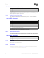
All RESERVED pins must be left unconnected. Connection of these pins to VCC, VSS, or to any
other signal (including each other) can result in component malfunction or incompatibility with
future processors. See Section 5 for a pin listing for the processor and the location of all
RESERVED pins.
For reliable operation, always terminate unused inputs or bidirectional signals to their respective
deasserted states. On-die termination has been included on the Dual-Core Intel Xeon processor
7000 series to allow signals to be terminated within the processor silicon. Most unused AGTL+
inputs may be left as no-connects since AGTL+ termination is provided on the processor silicon.
See Table 2-5 for details on AGTL+ signals that do not include on-die termination. Unused
active-high inputs should be connected through a resistor to ground (VSS). Unused outputs may be
left unconnected. However, this may interfere with some TAP functions, complicate debug
probing, and prevent boundary scan testing. A resistor must be used when tying bidirectional
signals to power or ground. When tying any signal to power or ground, a resistor will also allow for
system testability. For unused AGTL+ input or I/O signals, use pull-up resistors of the same value
as the on-die termination resistors (RTT). See Table 2-15.
TAP, Asynchronous GTL+ inputs, and Asynchronous GTL+ outputs do not include on-die
termination. Inputs and utilized outputs must be terminated on the baseboard. Unused outputs may
be terminated on the baseboard or left unconnected. Note that leaving unused outputs unterminated
may interfere with some TAP functions, complicate debug probing, and prevent boundary scan
testing. Signal termination for these signal types is discussed in the appropriate platform design
guidelines.
Don’t Care pins are pins on the processor package that are not connected to the processor die.
These pins can be connected on the motherboard in any way necessary for compatible motherboard
designs to support other processor versions.
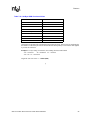
The TESTHI pins should be tied to VTT using a matched resistor, where a matched resistor has a
resistance value within ±20% of the impedance of the board transmission line traces. For example,
if the trace impedance is 50 Ω, then a value between 40 Ω and 60 Ω is required.
The TESTHI pins may use individual pull-up resistors or be grouped together as detailed below.
Please note that utilization of boundary scan test will not be functional if pins are connected
together. A matched resistor should be used for each group:
• TESTHI[3:0]
• TESTHI[6:5]
• TESTHI4 — cannot be grouped with other TESTHI signals
2.4
Mixing Processors
Intel supports and validates multi-processor configurations in which all processors operate with the
same FSB frequency and internal cache sizes. Intel does not support or validate operation of
processors with different cache sizes or mixed processor models. Mixing different processor
steppings but the same model is supported. Details on this process are provided in the Dual-Core
Intel® Xeon® Processor 7000 Sequence Specification Update, Prescott, Nocona and Potomac
Processor BIOS Writer’s Guide (BWG) document and the AP-485 Intel® Processor Identification
and the CPUID Instruction application note.
20
Dual-Core Intel® Xeon® Processor 7000 Series Datasheet