1
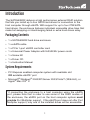
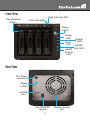
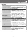
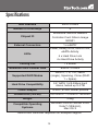
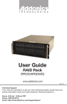
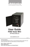
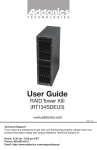
SAT3540ER2
Instruction Manual
SATA Hard Drive Enclosure
3.5” 4 Drive eSATA RAID
External Hard Drive Enclosure
with Controller Card
Manual Revision:06/28/2010
For the most up-to-date information, please visit www.startech.com
FCC Compliance Statement
This equipment has been tested and found to comply with the limits for a Class B digital
device, pursuant to part 15 of the FCC Rules. These limits are designed to provide
reasonable protection against harmful interference in a residential installation. This
equipment generates, uses and can radiate radio frequency energy and, if not installed
and used in accordance with the instructions, may cause harmful interference to radio
communications. However, there is no guarantee that interference will not occur in a
particular installation. If this equipment does cause harmful interference to radio or
television reception, which can be determined by turning the equipment off and on, the
user is encouraged to try to correct the interference by one or more of the following
measures:
• Reorient or relocate the receiving antenna.
• Increase the separation between the equipment and receiver.
• Connect the equipment into an outlet on a circuit different from that to which the receiver
is connected.
• Consult the dealer or an experienced radio/TV technician for help.
Use of Trademarks, Registered Trademarks, and other Protected Names and Symbols
This manual may make reference to trademarks, registered trademarks, and other
protected names and/or symbols of third-party companies not related in any way to
StarTech.com. Where they occur these references are for illustrative purposes only
and do not represent an endorsement of a product or service by StarTech.com, or an
endorsement of the product(s) to which this manual applies by the third-party company
in question. Regardless of any direct acknowledgement elsewhere in the body of
this document, StarTech.com hereby acknowledges that all trademarks, registered
trademarks, service marks, and other protected names and/or symbols contained in this
manual and related documents are the property of their respective holders.
Table of Contents
Introduction...................................................................... 1
Packaging Contents.....................................................................1
System Requirements..................................................................1
Front View.....................................................................................2
Rear View.....................................................................................2
Installation........................................................................ 3
Enclosure Installation...................................................................3
Driver Installation..........................................................................4
Controller Card Installation...........................................................4
Driver Installation..........................................................................5
How to Use....................................................................... 6
Software Installation.....................................................................6
RAID Levels..................................................................................12
Specifications................................................................... 13
Technical Support............................................................ 14
Warranty Information....................................................... 14
i
Introduction
The SAT3540ER2 delivers a high performance external RAID solution
that lets you install up to four SATA hard drives for connection to the
host computer through eSATA. With support for up to four 2TB SATA
hard drives, the enclosure features individual removable drive trays that
make hot swapping or interchanging failed or extra hard drives easy.
Packaging Contents
• 1 x SAT3540ER2 hard drive enclosure
• 1 x eSATA cable
• 1 x PCIe 1-port eSATA controller card
• 1 x Universal Power Adapter with NA/UK/EU power cords
• 1 x Screw Kit
• 1 x Driver CD
• 1 x Instruction Manual
System Requirements
• PCI Express enabled computer system with available slot
OR available eSATA* port
• Microsoft® Windows® 2000/XP/Server 2003/Vista/7 (32/64-bit), or
Apple® Mac OS® X
*If connecting the enclosure to a host computer using the eSATA
port, please note that in order to use some of the RAID modes of
the enclosure, the eSATA port on the host computer system must
provide Port Multiplier support. If the eSATA port does not offer Port
Multiplier support, only one of the installed drives will be accessible.
1
Front View
Disk Activity LED
Tray Release
button
Disk Link LED
Power
button
Power
LED
Error
LED
Ready
LED
eSATA
eSATA Link LED
Activity
LED
Rear View
DC Power
connector
Reset
button
eSATA
port
Fan ON/OFF
switch
2
80mm cooling
fan
Installation
WARNING: Hard drives require careful handling, especially when
being transported. If you are not careful with your hard disk, lost data
may result. Always handle your hard drive and storage device with
caution.
Enclosure Installation
1.Remove the drive trays from the enclosure, by pressing the release
button, then pushing down on the arms to eject them and slide the
trays out.
*installation photos are for reference only
2.Remove the screws holding in the plastic brace from the tray, then
secure the hard drive into the trays with the previously removed
screws. Repeat for each hard drive tray.
3.Slide the trays back into the enclosure until they are fully seated,
then close the arms.
4.Plug in the power adapter and press the power button on the front.
3
Driver Installation
No driver installation is required for these operating systems, as this
hard drive enclosure is natively supported, so the drivers are already
installed.
Controller Card Installation
WARNING! PCI Express cards, like all computer equipment, can be
severely damaged by static electricity. Be sure that you are properly
grounded before opening your computer case or touching your PCI
Express card. StarTech.com recommends that you wear an anti-static
strap when installing any computer component. If an anti-static strap
is unavailable, discharge yourself of any static electricity build-up by
touching a large grounded metal surface (such as the computer case)
for several seconds. Also be careful to handle the PCI Express card by
its edges and not the gold connectors.
1.Turn your computer off and any peripherals connected to the
computer (i.e. Printers, external hard drives, etc.). Unplug the power
cable from the rear of the power supply on the back of the computer.
2.Remove the cover from the computer case. See documentation for
your computer system for details.
3.Locate an open PCI Express slot and remove the metal cover plate
on the rear of the computer case (Refer to documentation for your
computer system for details.). Note that this card will work in PCI
Express slots of additional lanes (i.e. x4, x8 or x16 slots).
4.Insert the card into the open PCI Express slot and fasten the bracket
to the rear of the case. See documentation for your computer
system for details.
5.Place the cover back onto the computer case.
6.Insert the power cable into the socket on the power supply and
reconnect all other connectors removed in Step 1.
4
Driver Installation
Windows 2000/XP/Server 2003
1.When the Found New Hardware wizard appears on the screen,
insert the Driver CD into your CD/DVD drive. If you are prompted
to connect to Windows Update, please select the “No, not this time”
option and click Next.
2.Select the option “Install Drivers Automatically (Recommended)” and
then click the Next button.
3.Windows should now start searching for the drivers. Once this has
completed, click the Finish button.
Windows Vista/7
1.When the Found New Hardware window appears on the screen,
click on the “Locate and install drivers software (recommended)”
option. If prompted to search online, select the “Don’t search online”
option.
2.When prompted to insert the disc, insert the Driver CD that
came with the card, into your CD/DVD drive and Windows will
automatically proceed to search the CD.
3.If a Windows Security dialog window appears, click the “Install this
driver software anyway” option to proceed.
4.Once the driver is installed, click the Close button.
5
How to Use
Software Installation
1.Insert the included installation CD into your CD/DVD drive.
2.Double-click the Setup program to begin the installation procedure.
3.The Installation Wizard start screen appears. Click Install to
continue.
4.Wait for the installation process to complete.
5.Check or uncheck the box “Launch the application right now” and
then click Finish.
6.The Manager Utility is installed under the “Programs” section of the
Start Menu under “JMicron HW RAID Manager”.
6
Basic Mode
Basic mode is aimed at providing users with disk and RAID array
information, an event log, as well as perform the basic configurations
on the connected hard drives.
RAID and Disk Information
This section consists of two parts. The left side is a tree which shows
all controllers on the system and their connected RAID units and
hard drives in a hierarchy view. When an item is selected, the detailed
information of the selected item will be displayed on the right side. All
the hard drive and RAID information will be updated in real–time.
7
Controller Information
If a Controller item is selected from the tree view, it will display the
model name and capacity of any RAID units and hard drives connected
to the controller. For RAID member disks, the hard drive charts on the
right side will be shown with different colors according to the different
RAID level.
When moving the mouse over the “Controller Information” label, it will
be highlighted in red and show a tool-tip that tells that it can be clicked
to identify the selected controller with the specified host LED flashing.
RAID Information
If a RAID item is selected from the tree view, it will display information
for the specified RAID unit on the right side and also display the RAID
member disks below that.
If the selected RAID is in a rebuilding state, it will be highlighted in
green in the tree view, and the rebuilding animation will be displayed
at the bottom-left and right of the window. The rebuilding percentage is
displayed at the bottom-center.
Clicking the “RAID Information” label will identify the member disks of
the specified RAID with all disk LEDs flashing at the same time.
Disk Information
If a Disk item is selected from the tree view, it will display detailed
information of the specified hard drive on the right side and display a
pie chart below that.
If the disk is a RAID member, the application will show an “Advanced”
button in the bottom-right corner. Click on it to browse the SMART
information of the specified hard drive. If the selected disk is a member
of a rebuilding RAID, the rebuilding animation will be displayed at
the bottom-left and right of the window. The rebuilding percentage is
displayed at the bottom-center.
Clicking the “Disk Information” label will identify the specified hard drive
by flashing the disk LED.
8
Event Log Viewer
The RAID Manager will monitor the status of all connected hard drives
and RAID units and keep records of the occurrence of events. All
events can be viewed through this event log viewer page. Logs can be
saved to a profile by pressing the “Save to Profile” button or cleared by
pressing the “Clear” button.
Basic RAID Configuration
Basic RAID configurations for the connected hard drives can be setup
from here. Depending on the number and capacity of the connected
hard drives, different RAID modes will be made available. Selecting the
desired RAID type will automatically select the available disks to build
the RAID and calculate the RAID capacity. It will show the selected
disks charts drawn in the cross pattern on the right part.
For example, selecting RAID 10, the software will select four available
disks to build the RAID 10 starting with the lowest Disk number. At the
same time, it will determine the smallest disk size and calculate the
total capacity of the RAID unit.
A password can be set for the new RAID unit by checking the password
group box and entering the password below. To delete the existing
RAID, select the “DELETE ALL RAID” button and then press the
“Apply” button.
After selecting the RAID type and setting the password (optional),
9
press the “Apply” button to confirm the configuration or press the
“Cancel” button to restore to the original configuration. After the user
confirms to apply the configuration, it will pop up another progress
window to show the configuration status. After the RAID configuration
finishes, it will pop up a message dialog to tell that a RAID is newly
created or a RAID has been deleted. The disk charts on the right side
will be redrawn to reflect the result of the new configuration.
Advanced Mode
The advanced mode is aimed at providing advanced functionality, such
as Email notification settings, and the advanced RAID configuration.
Email Notification and Event Settings
The software provides the ability to send email notifications when a
specified event occurs. Enter the mail server name, mail server port,
sender e-mail address and recipients’ e-mail addresses in this page.
If the mail server needs to authenticate the sender’s password when
sending mail, a username and password may also be required.
To verify if the entered data is correct, click the “Send Mail Test” button
to send a test email to the specified recipient.
Additionally, the events for email notification may be selected. Save the
email and event settings to a profile by pressing the “Save To Profile”
button or load the settings from the specified profile by pressing “Load
From Profile” button.
Press the “Apply” button to confirm the specified email and event
settings or press the “Cancel” button to restore the original settings.
Advanced RAID Configuration
For advanced users, the software provides advanced RAID
configuration options for the connected disks. These options allows for
selection of the RAID type and also selection of the hard drives to use
in the RAID. After applying the RAID configuration, the disk charts are
updated and the available RAID types will also be updated according to
10
any remaining hard drives.
The RAID array size can be modified by simply clicking the specified
disk chart and adjusting the disk size with the slider at the bottom. The
RAID array can be deleted by checking the “Delete RAID” check box.
If the deleted RAID array is password protected, the password prompt
will automatically open.
Click the “Apply” button once all configuration settings are done.
11
RAID Levels
Clone (RAID 1 + Spare)
Creates a standard RAID 1 mirrored
array, and then uses an extra hard drive
as a spare, in case of failure of one of the
disks in the RAID 1.
Span (Concatenation)
Spanning concatenates (joins) multiple
hard drives into a single large disk.
Provides no performance or redundancy
benefits.
RAID 0 (Stripe)
Striping combines multiple disk into a
single large disk array. The data is split
evenly across each disk simultaneously.
Read/write performance is increased as
a result, but failure of any one disk will
make the entire array unusable.
RAID 1 (Mirror)
Mirroring writes the same data across
multiple disks, creating a mirror copy. This
provides redundancy in case one drive
fails.
RAID 5
Uses striping to write data to multiple
disks simultaneously and distribute parity
across multiple disks. Failure of any one
disk will still allow access to the data, until
the disk is replaced.
RAID 10 (1+0)
Creates a RAID 0 striped array, then
mirrors each striped disk. Combines
the performance of RAID 0 with the
redundancy of RAID 1.
12
Specifications
Bus Interface
SATA 3.0Gb/s
Number of Drive Bays
4
Enclosure: JMicron JMB393
Chipset ID
Controller Card: Silicon Image
SiI3531
External Connectors
1 x eSATA*
LEDs
Power, Ready, Error, eSATA Link,
eSATA Activity
4 x Hard Drive Link
4 x Hard Drive Activity
Cooling Fan
1 x 80mm
Maximum Data Transfer Rate
eSATA: 3.0Gb/s
Supported RAID Modes
RAID 0, 1, 5, 1+0, JBOD
(single), Spanning, Clone (RAID
1 + Spare)
Hard Drive Compatibility
3.5” SATA 1.5/3.0Gbps hard
drives, tested up to 2TB
Power Adapter
12VDC, 8.33A, center positive
Dimensions (LxWxH)
230.0mm x 170.0mm x 149.2mm
Weight
3.4kg
Compatible Operating
Systems
Windows 2000/XP/Server 2003/
Vista/7 (32/64-bit),
Mac OS X
* eSATA host controller requires Port Multiplier support
13
Technical Support
StarTech.com’s lifetime technical support is an integral part of our
commitment to provide industry-leading solutions. If you ever need
help with your product, visit www.startech.com/support and access
our comprehensive selection of online tools, documentation, and
downloads.
Warranty Information
This product is backed by a one year warranty.
In addition, StarTech.com warrants its products against defects in
materials and workmanship for the periods noted, following the initial
date of purchase. During this period, the products may be returned
for repair, or replacement with equivalent products at our discretion.
The warranty covers parts and labor costs only. StarTech.com does
not warrant its products from defects or damages arising from misuse,
abuse, alteration, or normal wear and tear.
Limitation of Liability
In no event shall the liability of StarTech.com Ltd. and StarTech.com USA
LLP (or their officers, directors, employees or agents) for any damages
(whether direct or indirect, special, punitive, incidental, consequential, or
otherwise), loss of profits, loss of business, or any pecuniary loss, arising
out of or related to the use of the product exceed the actual price paid
for the product. Some states do not allow the exclusion or limitation of
incidental or consequential damages. If such laws apply, the limitations
or exclusions contained in this statement may not apply to you.
14
StarTech.com has been making “hard-to-find easy” since 1985,
providing high quality solutions to a diverse IT and A/V customer
base that spans many channels, including government, education
and industrial facilities to name just a few. We offer an unmatched
selection of computer parts, cables, A/V products, KVM and Server
Management solutions, serving a worldwide market through our
locations in the United States, Canada, the United Kingdom and
Taiwan.
Visit www.startech.com today for complete information about all
our products and to access exclusive interactive tools such as the
Cable Finder, Parts Finder and the KVM Reference Guide.