1
SATARAID5™
Management Software
User’s Guide
Document Number: MAN-000SR5-000
Revision 1.40
Document Number: MAN-000SR5-000
Revision 1.40
Copyright © 2006, Silicon Image, Inc.
All rights reserved. No part of this publication may be reproduced, transmitted, transcribed, or translated into any
language or computer format, in any form or by any means without prior written permission of:
Silicon Image, Inc.
1060 East Arques Ave.
Sunnyvale CA 94085
Silicon Image, the Silicon Image logo and SATARAID5 are the trademarks or registered trademarks of Silicon Image, Inc.
("Silicon Image") in the United States and other countries. The information contained in this document is provided by
Silicon Image merely as a courtesy and is, to the knowledge of Silicon Image, accurate. However, Silicon Image is under
no obligation to update and/or keep current the information contained in the document. Silicon Image disclaims any and
all liability resulting from the use of the information contained in this document and any reliance on such information shall
be at the sole risk of the relying party. Silicon Image expressly reserves the right to change the information contained
herein without notice.
Windows is a registered trademark of Microsoft Corporation in the United States and other countries.
Apple, Mac and MacOS are trademarks of Apple Computer, Inc., registered in the United States and other countries.
Linux is a trademark of Linus Torvalds.
Sun, Sun Microsystems and JAVA are trademarks or registered trademarks of Sun Microsystems, Inc. in the United
States and other countries.
SATARAID5 Management Software User's Guide
Page ii
Document Number: MAN-000SR5-000
Revision 1.40
Contents
1
Welcome ......................................................................................................................................... 1
SATARAID5 Features.................................................................................................................................. 2
Data Security ............................................................................................................................................... 2
Data Performance ....................................................................................................................................... 2
Data Versatility ............................................................................................................................................ 2
Ease of Use.................................................................................................................................................. 2
2
Using the SATARAID5 Manager ................................................................................................... 3
Launching the SATARAID5 Manager ........................................................................................................ 3
Windows Systems....................................................................................................................................... 3
Macintosh Systems..................................................................................................................................... 3
Linux Systems............................................................................................................................................. 3
Creating RAID Groups ................................................................................................................................ 5
RAID Levels ................................................................................................................................................. 5
Disk Striping (RAID 0) ..........................................................................................................................................5
Disk Mirroring (RAID 1) .......................................................................................................................................6
Disk Mirroring and Striping (RAID 10).................................................................................................................6
Parity RAID (RAID 5) ...........................................................................................................................................6
Concatenated ..........................................................................................................................................................7
Just a Bunch of Disks (JBOD)................................................................................................................................7
RAID Volume Status ................................................................................................................................... 7
Creating a RAID Group ............................................................................................................................... 8
Additional SATARAID5 Manager Menu Options .................................................................................... 12
File Menu Options ..................................................................................................................................... 13
Configuration........................................................................................................................................................13
Exit ......................................................................................................................................................................15
Device Menu Options................................................................................................................................ 16
Create Spare .........................................................................................................................................................16
Delete Spare .........................................................................................................................................................17
Delete Member .....................................................................................................................................................17
Delete Orphan.......................................................................................................................................................18
Device Summary ..................................................................................................................................................19
RAID Group Menu Options....................................................................................................................... 20
SATARAID5 Management Software User's Guide
Page iii
Document Number: MAN-000SR5-000
Revision 1.40
Create RAID Group..............................................................................................................................................20
Rebuild RAID Group ...........................................................................................................................................21
Delete RAID Group..............................................................................................................................................21
RAID Group Summary.........................................................................................................................................22
Window Menu Options ............................................................................................................................. 24
Task Manager .......................................................................................................................................................24
Event Log .............................................................................................................................................................26
Resources .............................................................................................................................................................28
Legacy Support Menu...............................................................................................................................28
Create Legacy RAID Group .................................................................................................................................29
Rebuild Legacy RAID Group...............................................................................................................................30
Delete Legacy RAID Group .................................................................................................................................30
Convert Legacy RAID Group...............................................................................................................................31
Create Legacy Spare.............................................................................................................................................31
Delete Legacy Spare.............................................................................................................................................31
Convert Legacy Spare ..........................................................................................................................................32
Help Menu Options ................................................................................................................................... 33
Help Topics ..........................................................................................................................................................33
About....................................................................................................................................................................33
3
Managing Legacy RAID Groups with the BIOS RAID Utility.................................................... 34
Utility Overview ......................................................................................................................................... 34
Reserved Logical Drives and RAID Set Sizes ........................................................................................ 36
Creating RAID Groups (Sets) ................................................................................................................... 37
Creating a JBOD Configuration............................................................................................................... 40
Creating a Spare Drive for a RAID1 Group ............................................................................................. 40
Additional BIOS RAID Main Menu Options............................................................................................. 41
Delete RAID Set ......................................................................................................................................... 41
Rebuild RAID1 Set..................................................................................................................................... 42
Resolve Conflicts ...................................................................................................................................... 43
Low Level Format...................................................................................................................................... 43
Logical Drive Info ...................................................................................................................................... 44
4
Allocating Partitions .................................................................................................................... 45
Define a Partition on MS-Windows.......................................................................................................... 45
SATARAID5 Management Software User's Guide
Page iv
Document Number: MAN-000SR5-000
Revision 1.40
Define a Volume on Mac OS X ................................................................................................................. 50
Define a Volume/Partition on Linux ........................................................................................................ 52
Appendix A
Managing the BIOS .............................................................. 53
Control Panel Method ...............................................................................................................................53
Device Manager Method ........................................................................................................................... 54
SATARAID5 Management Software User's Guide
Page v
Document Number: MAN-000SR5-000
Revision 1.40
1
Welcome
Silicon Image’s SATARAID5TM product consists of a Serial-ATA controller, RAID controller BIOS, RAID
controller driver, and RAID Management Software. A Silicon Image controller provides the necessary
hardware for SATARAID5. The SiI3114, SiI3124, SiI3132 and SiI3531 controllers support SATARAID5
components.
SATA Gen
Host BUS
Channels
Description
A single-chip PCI to 4-port Serial ATA (SATA)
Generation I host controller.
SiI3114
I
PCI
4
SiI3124-1
I
PCI-X / PCI
4
A single-chip PCI-X to 4-port Serial ATA (SATA)
Generation I or II host controller that takes SATA
performance and features to enterprise levels.
SiI3124-2
II
SiI3132
II
PCI-Express
2
A single-chip, one-lane PCI-Express to 2-port
Serial ATA (SATA) Generation II host controller.
SiI3531
II
PCI-Express
1
A single-chip, one-lane PCI-Express to 1-port
Serial ATA (SATA) Generation II host controller.
The SATARAID5 controller’s BIOS provides boot-up support and a configuration interface. For AMD and
x86 systems, the SATARAID5 BIOS identifies present “Legacy RAID” volumes that may be used to boot-up
an operating system. The RAID controller BIOS also provides a basic, configuration interface that could be
used before an operating system is installed. See Additional BIOS RAID Main Menu Options for BIOS
configuration instructions and Legacy Support Menu for steps necessary to create a “Legacy RAID” volume
using the RAID Management Software.
The SATARAID5 Management software allows RAID configuration and monitoring from the operating
system. The Management software supports automatic rebuilds, rebuild task prioritization, and partial hard
disk allocation to a RAID volume.
Silicon Image’s SATARAID5 software enhances your data storage by combining advanced RAID features
typically seen on high-end systems with low-cost and high-capacity Serial ATA drives. By using industrystandard SATA drives and Silicon Image Host Bus Adapters (HBAs), you can achieve extraordinarily low
costs while remaining assured that your data is protected against hardware failure.
SATARAID5 also supports the latest SATA enhancements, including SATA-II Port Multiplier support, and
up to 3 Gbit/second transfer rates on SATA Gen 2 controllers.
SATARAID5 Management Software User's Guide
Page 1
Document Number: MAN-000SR5-000
Revision 1.40
SATARAID5 Features
Data Security
SATARAID5 provides our highest commitment to data security through the use of RAID architecture to back
up and protect data. RAID levels 1, 5, and 10 provide data security. SATARAID5 supports sophisticated
sparing support so that hardware failure risk can be minimized by automatically regenerating the failed disk’s
data on a backup disk. The software driver includes support for Self-Monitoring Analysis and Reporting
Technology (“S.M.A.R.T.”) to predict disk failures. Drives can be moved between controllers without losing
data.
Data Performance
SATARAID5 can increase storage throughput by combining the throughput of multiple drives into a single
volume. RAID levels 0, 5, and 10 support this ability.
Data Versatility
The driver supports Just a Bunch of Disks (JBOD) and Concatenated drives for applications that do not
require increased security or performance. The JBOD state may also be achieved with the driver’s
“Pass-Thru” feature. “Pass-Thru” allows access to a new hard disk or one without any SATARAID5
configuration.
Ease of Use
The SATARAID5 Manager GUI offers an easy-to-use utility to create and manage your storage. Creating and
deleting volumes is possible without requiring a restart of the operating system. Rebuilds never require the
data to be taken off-line.
Note: A known problem with some versions of Microsoft Windows may cause an unnecessary
Parity Rebuild operation following hibernation. To address this issue, please apply the patch
available from Microsoft at http://support.microsoft.com/?kbid=902853
SATARAID5 Management Software User's Guide
Page 2
Document Number: MAN-000SR5-000
2
Revision 1.40
Using the SATARAID5 Manager
This section explains how to use the SATARAID5 Manager graphical user interface (GUI) to create and
manage RAID groups. Please install the SATARAID5 Manager software as explained in the SATARAID5
Quick Installation Guide for your computer’s operating system before you perform these tasks. Refer to
Appendix A for information about managing the Flash BIOS of the RAID controller on a Windows system.
Note: Be sure to download and install the latest Java Run-Time Environment for your system.
Launching the SATARAID5 Manager
The SATARAID5 Manager consists of a daemon and Java-based GUI applet. Depending on the operating
system, the daemon runs as Windows Service or a script-launched background process responsible for
monitoring of the local SATARAID5 driver.
Windows Systems
On a Windows system, the SATARAID5 Manager GUI shortcut is installed in the Windows Startup folder to
be launched automatically whenever your system is rebooted. To manually start the SATARAID5 Manager,
click the Start button, open the SATARAID5 Manager program group, and click on the SATARAID5 icon.
Macintosh Systems
On a Macintosh system, the SATARAID5 Manager software is installed into the Applications /
Utilities / Silicon Image / SATARAID5 folder. You can launch it by navigating to that folder and
double-clicking on the icon for the SATARaid5.jar file.
Linux Systems
On a Linux system the SATARAID5 Manager and daemon can be installed into any subdirectory. Before
launching the SATARAID5 Manager, the driver must be installed and the daemon must be running in
background. If you are using a bootable version of the SATARAID5 driver, it is already included in your
Linux kernel. If you are not using a bootable version of the SATARAID5 driver, you must manually load the
driver by typing the following command:
•
insmod si3XXXr5.ko (where “3XXX” refers to your specific SATA controller chip)
Then, the daemon must be started. If the daemon has been incorporated into the startup scripts (typically
included within the /etc/rc directory structure, it will start automatically when you boot your system.
Otherwise, you must manually start the daemon in a background mode by typing the following command:
•
./SATARaid5ConfigServer &
Finally, you can launch the SATARAID Manager by typing the following command:
•
java –jar SATARaid5Manager
Note: The SATARAID5 Manager uses TCP port number “4242” for sending commands to the
daemon and obtaining status. If a firewall is active on your system, be sure to enable access to that
port number before launching the SATARAID5 Manager.
SATARAID5 Management Software User's Guide
Page 3
Document Number: MAN-000SR5-000
Revision 1.40
When you start the SATARAID5 Manager GUI, the following divided window appears.
Note: All of the SATARAID5 Manager screen illustrations are shown for Microsoft Windows. The
outer frame and buttons may appear slightly different on other operating system platforms. The
number of channels shown in this screen will vary according to the type of RAID controller that is
installed in your system. The Legacy Support menu item is not available on Macintosh systems.
The left RAID Groups window identifies SATA host adapters and configured RAID groups. If more than one
Silicon Image Host Bus Adapter is installed, you can switch between them by selecting any controller. This
also displays the RAID Groups currently defined for each controller window. Select a RAID Group to display
the segments associated with that volume in the Device Configuration window on the right. The Device
Configuration window identifies all physical drives and their partitions. If the controller supports SATA-II
Port Multipliers, there may be more than one device ID per SATA channel.
Throughout the Manager, different colors indicate the status of components as follows.
Color
Status
Green
Good. The component and all subcomponents are functioning correctly.
Yellow
Warning. The component, or at least one subcomponent, has failed or become unavailable and
requires service.
Red
Failed. The component, or at least one subcomponent, has failed.
Blue
Pass-Thru device. The component is valid, but it does not contain any RAID metadata, so it will
function as an ordinary hard disk drive.
White
Gray
A square with capacity shows an unallocated driver reserved for configuration into a RAID set.
An empty square presents a free slot that will be filled by adding a hard disk drive to the system.
Unused.
Note: Throughout this manual, the term “right-click” refers to using the secondary button on your
mouse to perform the indicated operation. On a Windows or Linux system, use the mouse button
that you have defined to be the “right” button (which by default is on the right side of the mouse,
unless you have changed the primary and secondary buttons using Control Panel Æ Mouse on
Windows). On a Macintosh system, press and hold the COMMAND (Apple) button and click the
mouse.
SATARAID5 Management Software User's Guide
Page 4
Document Number: MAN-000SR5-000
Revision 1.40
Creating RAID Groups
Redundant Array of Independent Disks (RAID) technology allows one or more disks to be combined into a
logical volume, which provides greater performance and/or protection than standard disk drives. These
volumes, known as RAID Groups, appear like regular disk drives to the operating system and can be
partitioned, formatted and used just like any other disk. The RAID complexity is hidden within the driver.
Note: The maximum allowable size of a RAID group that can be created by the SATARAID5
Manager is 144,115,188,075,855,872 bytes (which represents 248 bit addressability). However,
some Linux platforms may limit the maximum size of a volume to 2TB, so the largest allowable size
of a RAID group is 2,199,023,255,552 bytes.
RAID Levels
There are several methods of combining disks, each with its own advantages and disadvantages. Each method
is referred to as a RAID “level,” such as RAID 1 or RAID 5. The details of each level are summarized below
and detailed in the following sections.
RAID Level
Advantages
Disadvantages
RAID 0
High performance, low cost.
No data protection.
RAID 1
Excellent data protection.
High cost.
RAID 5
Good data protection, good value.
Performance degradation on writes.
RAID 10
High performance, excellent data
protection.
High cost.
Concatenated
Good performance, low cost, large
volume size.
No data protection.
JBOD
Same as single disk.
Same as single disk.
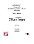
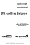
Disk Striping (RAID 0)
Striping is a performance-oriented, non-redundant data mapping technique. While Striping is discussed as a
RAID Group type, it is does not provide any fault tolerance. With modern SATA and ATA bus mastering
technology, multiple I/O operations can be performed in parallel, enhancing data throughput. Striping arrays
use multiple disks to form a larger virtual disk. The figure below illustrates a three-disk stripe set. Stripe one
is written to disk one, stripe two to disk two, and so forth. RAID 0 sets can include two, three, four or five
drives. If the sizes of the disk segments are different, the smallest disk segment will limit the overall size of
the RAID Group.
Stripe 1
Stripe 2
Stripe 3
Stripe 4
Stripe 5
Stripe 6
Stripe 7
Stripe 8
Stripe 9
Stripe 10
Stripe 11
Stripe 0
SATARAID5 Management Software User's Guide
Page 5
Document Number: MAN-000SR5-000
Revision 1.40
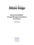
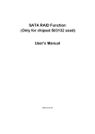
Disk Mirroring (RAID 1)
Disk mirroring creates an identical twin for a selected disk by having the data simultaneously written to two
disks. This redundancy provides instantaneous protection from a single disk failure. If a read failure occurs on
one drive, the system reads the data from the other drive. RAID 1 sets are typically comprised of two drives,
and a third drive can be allocated as a spare in case one of the drives in the set fails. Additional drives can be
configured as part of a mirrored set, but without much added benefit. If the sizes of the disk segments are
different, the smallest disk segment will limit the overall size of the RAID Group.
Block 0
Block 1
Block 0
Block 2
Block 1
Block 3
Block 2
Block 3
Disk Mirroring and Striping (RAID 10)
RAID 10 combines the features of both RAID 0 and RAID 1. Performance is provided through the use of
Striping (RAID 0), while adding the fault tolerance of Mirroring (RAID 1). The implementation of RAID 10
requires four drives. The drives are assigned as two sets of mirrored pairs.
The data is written to RAID Group A, which is mirrored (RAID 1) and provides data redundancy. Alternating
blocks of data are then striped across another RAID 1 mirrored set, shown as Set B in the figure above. This
provides improved speed.
Under certain circumstances, a RAID 10 set can sustain multiple simultaneous drive failures.
Parity RAID (RAID 5)
Parity RAID, or RAID 5, adds fault tolerance to Disk Striping by including parity information with the data.
Parity RAID dedicates the equivalent of one disk for storing parity stripes. The data and parity information is
arranged on the disk array so that parity is written to different disks. There are at least 3 members to a Parity
RAID set. The following example illustrates how the parity is rotated from disk to disk.
Parity RAID uses less capacity for protection and is the preferred method to reduce the cost per megabyte for
larger installations. Mirroring requires 100% increase in capacity to protect the data whereas the above
example using three hard drives only requires a 50% increase. The additional required capacity decreases as
the number of disks in the group increases (i.e., 33% for four drives or 25% for five drives).
SATARAID5 Management Software User's Guide
Page 6
Document Number: MAN-000SR5-000
Revision 1.40
In exchange for low overhead necessary to implement protection, Parity RAID degrades performance for all
write operations. The parity calculations for Parity RAID may result in write performance that is somewhat
slower than the write performance to a single disk.
Concatenated
The Concatenated mode combines multiple disks or segments of disks into a single large volume. It does not
provide any data protection or performance improvement but can be useful for utilizing leftover space on
disks. Concatenation allows the segments that make up the volume to be of different sizes.
Just a Bunch of Disks (JBOD)
The JBOD is a virtual disk that can either be an entire disk drive or a segment of a single disk drive. JBOD is
the Contiguous configuration option when creating RAID Groups (or sets) in the SATARAID5 Manager
utility.
RAID Volume Status
A RAID volume can be in any one of the following statuses.
Status
Meaning
Good
All disks are currently functioning as normal.
Reduced
For RAID levels that provide data protection, one or more disks have failed but
the data is still available via the RAID algorithms. The failed disk should be
replaced as soon as possible to avoid loss of data.
Rebuilding
A failed disk drive has been replaced and the data is being regenerated on the
replacement disk. When complete, the RAID Group will return to Good status.
Resynchronizing
An error has occurred and requires that the RAID algorithms be regenerated on
this RAID Group. When complete, the RAID Group will return to Good status.
Failed
One or more disks have failed and RAID algorithms can no longer regenerate
the data. The minimum number of failures required to reach this state depends
on the RAID level:
• RAID 0, Concatenated, JBOD/Contiguous: Single-disk failure.
• RAID 1, 5, 10: Two-disk failure.
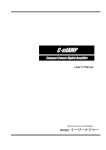
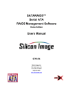
For increased versatility, the SATARAID5 software allows individual disks to be divided into smaller
segments that can then be combined into different volumes. As an example, if a user has one set of data that
must be protected at all costs, another set of data that should be protected at reasonable cost, and another set
that needs no protection at all, the user can divide three disks into segments as shown in Figure 1.
SATARAID5 Management Software User's Guide
Page 7
Document Number: MAN-000SR5-000
Revision 1.40
•
The yellow segments define the high-security volume.
•
The green segments represent the middle-security volume.
•
The light blue segments represent the unprotected volume.
Figure 1 Dividing disks into segments
Creating a RAID Group
When creating a RAID Group, you can use the available capacity on any hard disk that is connected to
your system. You can include disk devices that have never before been used to store data. You can also
include disk devices that have previously been designated as Pass-Thru devices if those disks are no
longer needed as Pass-Thru devices. However, data that has already been stored on a Pass-Thru device
will be overwritten when the hard disk drive becomes a member of a newly created RAID Group. To
create a RAID Group, use the following procedure:
1.
Select Create RAID Group from the RAID Group menu or right-click a controller in the RAID
Groups window and select Create RAID Group from the pop-up menu.
Note: Throughout this manual, the term “right-click” refers to using the secondary button on your
mouse to perform the indicated operation. On a Windows or Linux system, use the mouse button
that you have defined to be the “right” button (which by default is on the right side of the mouse,
unless you have changed the primary and secondary buttons using Control Panel Æ Mouse on
Windows). On a Macintosh system, press and hold the COMMAND (Apple) button and click the
mouse.
SATARAID5 Management Software User's Guide
Page 8
Document Number: MAN-000SR5-000
Create RAID Group dialog
(for Contiguous, Concatenated and
Striped configurations)
2.
Revision 1.40
Create RAID Group dialog
(for Mirrored, Mirrored/Striped and
Parity RAID configurations)
Enter values in all fields and click Create to create the RAID Group.
Field
Definition
RAID Group
Label
Enter an identifiable name for the RAID group. This value can be any string (up
to 8 characters including blank spaces) to help users identify this volume.
RAID Group
Select a Group ID from the available ID list. The maximum number of RAID
Groups per controller is 8, so Group ID can be any number between 0 and 7,
inclusive.
Configuration
Select which RAID level is to be used to configure these members:
• Contiguous (for virtual disk or JBOD).
• Concatenated (for multiple concatenated segments).
• Striped (for RAID 0)
• Mirrored (for RAID 1)
• Mirrored Striped (for RAID 10)
• Parity RAID (for RAID 5)
Capacity
Select a value to define the total usable capacity of the RAID Group or manually
enter the volume size in gigabytes (GB). Selecting MAX will create the largest
RAID set possible with the drive(s) selected.
Chunk Size
Select a value to define the chunk size (stripe size) for performance tuning. In
general, large stripe sizes are best for large files that are accessed sequentially
(for example, media streaming files) and smaller sizes are better for randomly
accessed data like databases. This parameter is not used for Contiguous (JBOD),
Concatenated, and Mirrored configurations.
SATARAID5 Management Software User's Guide
Page 9
Document Number: MAN-000SR5-000
Revision 1.40
Field
Definition
Rebuild Priority
Select a value to identify how quickly the controller should rebuild data on a disk
after a hardware failure. A value of 1 is the lowest priority and will take the
longest to rebuild. A value of 10 is the highest priority and will rebuild the
fastest, but may require more CPU resources, which might affect the computer’s
performance. This parameter is not used for Contiguous (JBOD), Concatenated,
and Striped configurations.
Check Pointing
Click the radio button to toggle the state of the Check Pointing feature. When
Check Pointing is enabled, restoring data is very fast after an unexpected power
loss, although normal performance may be slightly reduced. When Check
Pointing is disabled, normal performance is improved, but restores can take a
long time to complete. This selection is only available when the selected RAID
configuration is Mirrored, Mirrored Striped or Parity RAID, and the “Advanced
RAID Features” checkbox in the Configuration/Advanced Options dialog box is
checked.
Parity
Click the radio button to toggle the state of rebuild ability without taking the
volume off-line. This selection is only available when the selected RAID
configuration is Parity RAID and the “Advanced RAID Features” checkbox in
the Configuration/Advanced Options dialog box is checked.
Devices
Select the RAID member devices from the available device segment grid. Up to
five members can be selected for Contiguous, Concatenated, Mirrored, Striped or
Parity RAID modes (although Mirrored RAID Groups will typically contain only
two members). Exactly four members must be selected for Mirrored Striped
mode. Pass-Thru devices will appear with a highlighted background color.
3.
If you selected Concatenated in the Configuration field, enter values for individual segment sizes for
each disk and click Create to create the RAID Group.
4.
If you selected Pass-Thru devices as part of the this RAID Group, the following warning appears:
If you want to proceed with creating the RAID Group (which will destroy any existing data that is
stored on the Pass-Thru device, select Yes. Otherwise, select No to return to the Create RAID Group
dialog.
5.
When you are finished, press Cancel to close the Create RAID Group dialog box.
SATARAID5 Management Software User's Guide
Page 10
Document Number: MAN-000SR5-000
Revision 1.40
Note: Depending on the manufacturer and capacity of the hard drives that you are using, a
small amount of the total disk capacity (less than the amount of one chunk size) may not be
available, especially if you have selected one of the larger chunk sizes.
6.
Refer to Chapter 4, Allocating Partitions for information about how to define partitions and volumes
for the RAID Groups you created.
SATARAID5 Management Software User's Guide
Page 11
Document Number: MAN-000SR5-000
Revision 1.40
Additional SATARAID5 Manager Menu Options
This section documents the options available in the SATARAID5 Manager menus.
Note: All of the SATARAID5 Manager screen illustrations are shown for Microsoft Windows. The
frame and buttons may appear slightly different on other operating system platforms. The number
of channels shown in this screen will vary according to the type of RAID controller that is installed
in your system. The Legacy Support menu item is not available on Macintosh systems.
SATARAID5 Management Software User's Guide
Page 12
Document Number: MAN-000SR5-000
Revision 1.40
File Menu Options
Configuration
This menu option displays a tabbed dialog box to customize the settings for the Log File location and name,
Popup notification messages, and Advanced Options:
•
The Log File tab allows you to define the location and name of the log file. The log file is used
to store event information received from all Silicon Image RAID drivers. The log file is a text
file and can be viewed with any text viewer (such as “Notepad” on Windows platforms) or with
the Event Log window of the SATARAID5 Manager.
To specify whether the Log File is generated, click on either the Disabled or Enabled radio button.
If Log File generation is enabled, you can click the Browse button to specify the file name and
location of the Log File. You can also use the Purge button to delete the contents of the Log File.
SATARAID5 Management Software User's Guide
Page 13
Document Number: MAN-000SR5-000
•
Revision 1.40
The Popup tab allows you to define the type of events to trigger notification messages in popup
windows. Use the slider control to select an event level. Select:
•
Informational to display Informational, Warning, and Error events in a popup window.
•
Warning to display Warning and Error events in a popup window.
•
Error to display Error events in a popup window.
•
Disabled to turn off popup notification messages.
SATARAID5 Management Software User's Guide
Page 14
Document Number: MAN-000SR5-000
•
Revision 1.40
The Advanced Options tab allows you to enable the following advanced features.
Feature
Explanation
Legacy (Bootable)
Support
Enables the Legacy Support menu to support RAID functions for legacy
RAID groups (available on Windows and Linux platforms only). See
Legacy Support menu options.
Delete Member
Support
Enables the Delete Member option on the Device menu to delete a
member from RAID 1 (Mirrored), RAID 5 (Parity RAID), and RAID
10 (Striped and Mirrored) groups. See Delete Member menu option.
Advanced RAID
Features
Enables the selection of an Improper Shutdown Policy (including
Check-Pointing and Dirty Parity handling) in the Create RAID Group
dialog box when the selected RAID Group type is a fault-tolerant
configuration (Mirrored, Mirrored/Striped and Parity RAID). This
feature is not supported for Legacy RAID groups.
Resources Info
Support
Enables the Resources option on the Window menu for debugging
purposes. See Resources menu option.
Exit
This menu option terminates the SATARAID5 Manager GUI.
SATARAID5 Management Software User's Guide
Page 15
Document Number: MAN-000SR5-000
Revision 1.40
Device Menu Options
Create Spare
This menu option displays a dialog box to create a spare disk drive. Enter values for the following parameters.
Parameter
Description
Spare Type
Choose one of:
• Global if the spare drive is for all RAID groups in the system.
• Dedicated if the spare drive is dedicated to a specified RAID group.
Capacity
If you selected Global for the Spare Type, select from a list of spare drive sizes.
Options include sizes from 128 MB to 100 GB, plus MAX.
RAID Group
If you selected Dedicated for the Spare Type, select the RAID group to which
this spare drive is dedicated.
Device Segment
Select one device segment from the available device segment grid (Global
Spare Type only.
Create Spare dialog
(Global Spare Type)
Create Spare dialog
(Dedicated Spare Type)
SATARAID5 Management Software User's Guide
Page 16
Document Number: MAN-000SR5-000
Revision 1.40
Delete Spare
This menu option displays a dialog box to select (highlight) one or more spare drives to delete. This item is
only selectable when one or more spare exists.
Delete Member
This menu option displays a dialog box to select (highlight) RAID group members to delete. Because RAID 0
is not fault tolerant, RAID 0 members are not shown in the list.
Note: Deleting members will demote the RAID group to a non-fault-tolerant RAID group.
SATARAID5 Management Software User's Guide
Page 17
Document Number: MAN-000SR5-000
Revision 1.40
Delete Orphan
This menu option displays a dialog box to select (highlight) orphan segments to delete. An orphan segment is
part of a RAID group that cannot access other segments within the same RAID group. When a member of a
RAID group fails in a severe manner (such as a loss of power or a complete hard disk failure), it becomes an
orphan. This item is only selectable when one or more orphan segments exist.
Make Pass-Thru
This menu option displays a dialog box to select (highlight) available reserved devices that you can convert to
Pass-Thru mode. Devices allocated to an existing RAID Groups are not included in this list.
Select one or more devices that you want to convert to Pass-Thru devices and then click the Convert button.
The following warning appears:
SATARAID5 Management Software User's Guide
Page 18
Document Number: MAN-000SR5-000
Revision 1.40
To proceed with the conversion to Pass-Thru mode, click Yes. Otherwise, click No to return to the Make
Pass-Thru dialog.
Note: After you create a Pass-Thru device, be sure to delete any partition information that may
have been associated with that device.
Device Summary
This menu option displays the Device Summary window to show all physical devices’ segments.
The Capacity field indicates the number of 512-byte blocks that are available on the device. Items that
appear with a highlighted background color are Pass-Thru devices.
The Device Summary window has its own menu bar.
•
File > Exit closes the Device Summary window.
SATARAID5 Management Software User's Guide
Page 19
Document Number: MAN-000SR5-000
Revision 1.40
•
Options > Sorting displays a dialog box to sort the rows based on the selected field.
•
Options > Fields displays a dialog box to choose which fields will be shown in the Device
Summary window.
RAID Group Menu Options
Create RAID Group
This primary menu option is described in Creating a RAID Group.
SATARAID5 Management Software User's Guide
Page 20
Document Number: MAN-000SR5-000
Revision 1.40
Rebuild RAID Group
This menu option displays a dialog box to choose a replacement segment to rebuild a reduced RAID group.
Delete RAID Group
This menu option displays a dialog box to select (highlight) RAID groups to delete.
Note: After you delete a RAID Group, be sure to delete any partition information that may have
been associated with that RAID Group.
SATARAID5 Management Software User's Guide
Page 21
Document Number: MAN-000SR5-000
Revision 1.40
RAID Group Summary
This menu option displays a dialog box to show the group ID, label, configuration, and status for all RAID
groups.
The RAID Group Summary window has its own menu bar.
•
File > Exit closes the RAID Group Summary window.
•
Options > Sorting displays a dialog box to sort items in the RAID Group list.
SATARAID5 Management Software User's Guide
Page 22
Document Number: MAN-000SR5-000
•
Revision 1.40
Options > Fields displays a dialog box to choose which fields will be shown in the RAID Group
Summary window.
SATARAID5 Management Software User's Guide
Page 23
Document Number: MAN-000SR5-000
Revision 1.40
Window Menu Options
Task Manager
This menu option displays the Task Manager window, which lists all RAID and disk management tasks that
have been started or finished. You can set the priority any RAID and disk management operations, such as
RAID group creation, rebuild, and test.
The Task Manager window has its own menu bar.
•
File > Open will be activated in a future release.
•
File > Save will be activated in a future release.
•
File > Print will be activated in a future release.
•
File > Exit closes the Task manager window.
•
Options > Sorting displays a dialog box to sort items in the task list.
SATARAID5 Management Software User's Guide
Page 24
Document Number: MAN-000SR5-000
Revision 1.40
•
Options > Fields displays a dialog box to choose which fields will be shown in the task list.
•
Task > Modify lets you modify parameters of the selected task items. The following is an
example of changing rebuild priority for a rebuild task.
•
Task > Suspend lets you suspend the selected task items.
•
Task > Resume lets you resume previously suspended task items.
SATARAID5 Management Software User's Guide
Page 25
Document Number: MAN-000SR5-000
Revision 1.40
•
Task > Cancel lets you cancel the selected tasks, after confirming the cancellation. This option
does not permanently delete the tasks.
•
Task > Delete lets you delete the selected tasks, after confirming the deletion.
Event Log
This menu option displays the Event Log window, which lists SATA device-related events that occur while
the SATARAID5 software is running.
SATARAID5 Management Software User's Guide
Page 26
Document Number: MAN-000SR5-000
Revision 1.40
The Event Log window has its own menu bar.
•
File > Exit closes the Event Log window.
•
Options > Sorting displays a dialog box to choose up to three fields to sort items in the Event Log
window.
•
Options > Fields displays a dialog box to choose which fields will be shown in the Event Log
window.
SATARAID5 Management Software User's Guide
Page 27
Document Number: MAN-000SR5-000
Revision 1.40
Resources
This menu option displays the Resource Information window. This feature is for debugging purpose only.
Legacy Support Menu
On Windows and Linux platforms, you can create and manage Legacy RAID sets and JBOD using the
SATARAID5 GUI or the BIOS RAID utility. Previous RAID drivers that do not support RAID 5
functionality are known as “Legacy” drivers and are being replaced with the SATARAID5 software. Legacy
RAID volumes are supported by the SATARAID5 software and have the following benefits:
•
Legacy volumes can be used as boot devices.
•
Legacy volumes can be created and managed by the BIOS menu during system boot.
•
Legacy RAID 0 and 10 volumes support a stripe size of 4K.
Note: Legacy Support is not available on Macintosh platforms, and that menu item does not
appear.
SATARAID5 Management Software User's Guide
Page 28
Document Number: MAN-000SR5-000
Revision 1.40
Create Legacy RAID Group
This menu option is disabled if new RAID groups exist. If enabled, this menu option displays a dialog box to
create a legacy RAID group. Enter values for the following parameters.
Parameter
Description
RAID Group
Select a group ID from the available ID list. The maximum number of Legacy
RAID Groups is limited to the number of hard drives that are connected to the
RAID controller.
Configuration
Select one of:
• Striped (for RAID 0)
• Mirrored (for RAID 1)
• Mirrored Striped (for RAID 10)
• Parity RAID (for RAID 5)
Capacity
Select from a list of RAID group sizes. Options include sizes from 256 MB to
100 GB, plus MAX.
Chunk Size
Select a value from the available list to define the chunk size (stripe size) for
performance tuning: 8, 16, 32, 64, 128 (KB). Mirrored (RAID 1) does not
require a chunk size.
Rebuild Priority
Select a value to identify how quickly the controller should rebuild data on a
disk after a hardware failure. A value of 1 is the lowest priority and will take
the longest to rebuild. A value of 10 is the highest priority and will rebuild the
fastest, but may require more CPU resources, which might affect the computer’s
performance. Striped (RAID 0) does not use this value.
Devices
Select RAID member devices from the available device segment grid.
SATARAID5 Management Software User's Guide
Page 29
Document Number: MAN-000SR5-000
Revision 1.40
Rebuild Legacy RAID Group
This menu option displays a dialog box to choose a replacement segment to rebuild a non-fault tolerant legacy
RAID group.
Delete Legacy RAID Group
This menu option displays a dialog box to select (highlight) legacy RAID groups to delete. This option is
disabled if no legacy RAID groups exist.
Note: After you delete a Legacy RAID Group, be sure to delete any partition information that may
have been associated with that Legacy RAID Group.
SATARAID5 Management Software User's Guide
Page 30
Document Number: MAN-000SR5-000
Revision 1.40
Convert Legacy RAID Group
This menu option displays a dialog box to select (highlight) legacy RAID groups to convert to new RAID
groups of the same RAID type (configuration). This option is disabled if no legacy RAID groups exist.
Create Legacy Spare
This menu option displays a dialog box to create a legacy spare drive. This option is disabled if new RAID
groups exist.
Delete Legacy Spare
This menu option displays a dialog box to select (highlight) a legacy spare drive to delete. This option is
disabled if no legacy spare drives exist.
SATARAID5 Management Software User's Guide
Page 31
Document Number: MAN-000SR5-000
Revision 1.40
Convert Legacy Spare
This menu option displays a dialog box to select (highlight) legacy spare drives to convert to new spare drives.
This option is disabled if no legacy spare drives exist.
SATARAID5 Management Software User's Guide
Page 32
Document Number: MAN-000SR5-000
Revision 1.40
Help Menu Options
Help Topics
This menu option is not currently available.
About
This menu option displays information about the SATARAID5 software, including its version, operating
system and Java Run-Time Environment version.
SATARAID5 Management Software User's Guide
Page 33
Document Number: MAN-000SR5-000
3
Revision 1.40
Managing Legacy RAID Groups
with the BIOS RAID Utility
On Windows and Linux platforms with RAID controllers that have two or more ports, you can create and
manage legacy RAID sets and JBOD using the BIOS RAID utility or the SATARAID5 GUI. You can create
and manage new RAID groups only from the SATARAID5 Manager GUI.
Utility Overview
During the system boot-up process and before the Operating System loads, the following message appears for
about 5 seconds. Press CTRL+S or the F4 key to enter the BIOS RAID utility.
If you are prompted whether to enable large disk support, respond Y so that you can create RAID groups on
large disks that the BIOS RAID utility detected.
SATARAID5 Management Software User's Guide
Page 34
Document Number: MAN-000SR5-000
Revision 1.40
The RAID Configuration Utility screen is divided into four main sections and a command line.
•
The Main Menu section in the upper left lists actions to be performed. Select:
• Create RAID Group to create a new legacy RAID Set or allocate legacy spare drives.
• Delete RAID Group to delete a legacy RAID Set or de-allocate a legacy spare drive.
• Rebuild RAID 1 Set to initiate the rebuild of a RAID 1 set after replacing a drive in the
Group.
• Resolve Conflicts to find the member drives of a disrupted RAID set and restore the Set to
proper operation. Do this after moving physical drives.
• Low Level Format to wipe the data from a single drive. Do not format drives assigned to Sets
or allocated as spares.
• Logical Drive Info to show the current configuration of each RAID set, allocated spare, and
unallocated physical drive attached to the SATA host adapter.
•
The Help section in the upper right displays context-sensitive help and status messages.
•
The Physical Drive section in the lower left displays the model number and capacities of the
drives physically attached to the SATA host adapter.
•
The Logical Drive section in the lower right displays all logical drives connected to the
controller.
• RAID sets and JBOD drives reported to the system BIOS are listed at the top of this section.
• Spare drives, reserved drives, conflict drives, and invalid drives not reported to the system
BIOS are listed at the bottom of this section.
•
The Command Line at the bottom of the screen lists the currently active command keys. Use:
• Up and Down arrows to select a menu option or action.
• ESC to go to the previous menu.
• Enter to select the highlighted choice.
• Ctrl-E to exit the utility.
Other keys may be active depending upon the currently selected action.
SATARAID5 Management Software User's Guide
Page 35
Document Number: MAN-000SR5-000
Revision 1.40
Reserved Logical Drives and RAID Set Sizes
When you create a RAID set, spare drive, or JBOD on a physical drive, the BIOS RAID utility saves metadata
for the configuration in a reserved area of the physical drive. That metadata is not deleted when a RAID set or
drive is deleted. After a set or drive is deleted, the BIOS RAID utility recognizes the physical drive as a
reserved logical drive and does not report the drive to the system BIOS.
When creating a RAID set, spare drive, or JBOD, one creation parameter is the size of the set or drive. You
can accept the default size or you can use the ↑ and ↓ keys to change the size.
•
If the physical drive has not yet been used to create a RAID set or drive, the BIOS RAID utility
shows the full size of the physical drive as the default size.
•
If the physical drive has previously been used, the utility shows the size that was saved in the
reserved area of the physical drive.
When you increase the default size (using the ↑ key), the utility displays a warning message in the Help
section of the RAID Configuration Utility screen and waits for you to confirm the size increase before
changing the default size.
SATARAID5 Management Software User's Guide
Page 36
Document Number: MAN-000SR5-000
Revision 1.40
Creating RAID Groups (Sets)
Select from RAID0, RAID1, and JBOD configurations when creating a new RAID group. Select a RAID
level based on factors such as performance, data security, and number of drives available. Consider the longterm role of the system and plan the data storage strategy appropriately.
1.
Select Create RAID set from the Main Menu section of the RAID Configuration Utility screen.
2.
Select RAID0 (Striped) or RAID1 (Mirrored) and press Enter.
Note: Procedures to create a JBOD configuration or a spare drive for a RAID1 set are
documented separately. See Creating a JBOD Configuration and Creating a Spare Drive for
a RAID1 Group.
SATARAID5 Management Software User's Guide
Page 37
Document Number: MAN-000SR5-000
3.
Revision 1.40
Select Auto configuration or Manual configuration of the RAID Set and press Enter.
•
If you select Auto configuration, the BIOS RAID utility selects RAID member drives
automatically and sets the chunk (stripe) size for striped sets to 64KB.
•
If you select Manual configuration, select the chunk size for Striped Sets or select the
Source and Target drives for mirrored sets.
SATARAID5 Management Software User's Guide
Page 38
Document Number: MAN-000SR5-000
Revision 1.40
4.
Select the size of the RAID set with the ↑ and ↓ keys and press Enter.
5.
When the Are You Sure? confirmation prompt appears, respond Y to complete the RAID Set
configuration.
Note: If you have excess capacity left on the hard drives after creating a RAID set in the
BIOS RAID utility, you can later go to the SATARAID5 Manager GUI to create additional
logical drives that fully utilize the capacity of all hard drives.
SATARAID5 Management Software User's Guide
Page 39
Document Number: MAN-000SR5-000
Revision 1.40
Creating a JBOD Configuration
The BIOS RAID utility does not report non-RAID drives to the system BIOS. If a non-RAID boot drive or
data drive is desired, create a JBOD so the BIOS RAID utility will report the drive to the system BIOS.
1.
Select Create RAID set from the Main Menu section of the RAID Configuration Utility screen.
2.
Select JBOD and press Enter.
3.
Select JBOD drive from the Physical Drive list and press Enter.
4.
Select the size of the JBOD drive with the ↑ and ↓ keys and press Enter.
5.
When the Are You Sure? confirmation prompt appears, respond Y to complete the JBOD
configuration.
Creating a Spare Drive for a RAID1 Group
If a RAID 1 set exists, you can create a spare drive for the set. The spare drive can then be allocated to the
RAID 1 set if a drive in the RAID 1 set fails.
1.
Select Create RAID set from the Main Menu section of the RAID Configuration Utility screen.
2.
Select Spare Drive and press Enter.
3.
Select a spare drive from the Physical Drive list and press Enter.
4.
Select the size of the spare drive with the ↑ and ↓ keys and press Enter.
5.
When the Are You Sure? confirmation prompt appears, respond Y to complete the spare drive
creation.
SATARAID5 Management Software User's Guide
Page 40
Document Number: MAN-000SR5-000
Revision 1.40
Additional BIOS RAID Main Menu Options
This section documents additional actions you can perform by selecting menu options in the Main Menu
section of the RAID Configuration Utility screen.
Delete RAID Set
Use the Delete RAID set menu option to remove a RAID set, spare drive, or JBOD.
1.
Select Delete RAID set from the Main Menu section of the RAID Configuration Utility screen.
2.
Select the item to delete from the Logical Drive list and press Enter.
3.
When the Are You Sure? confirmation prompt appears, respond Y to delete the selected RAID set,
spare drive, or JBOD.
The screen then displays a selection of logical drives from which to create a new RAID set.
Note: After you delete a RAID Group, be sure to delete any partition information that may
have been associated with that RAID Group.
SATARAID5 Management Software User's Guide
Page 41
Document Number: MAN-000SR5-000
Revision 1.40
Rebuild RAID1 Set
Rebuilding a RAID1 set copies data from an existing drive to a replacement drive that has been installed in a
RAID1 set. Take this action if any member of the RAID1 set fails.
1.
Select Rebuild Raid1 set from the Main Menu section of the RAID Configuration Utility screen.
2.
Select the RAID1 set to rebuild from the Logical Drive list and press Enter.
3.
When the Are You Sure? confirmation prompt appears, respond Y to rebuild the RAID1 set.
The set is rebuilt. A progress indicator appears in the Main Menu section during the rebuild.
SATARAID5 Management Software User's Guide
Page 42
Document Number: MAN-000SR5-000
Revision 1.40
Resolve Conflicts
When a RAID set is created, metadata of drive-connection information, including the channel on the host
adapter to which it is connected, is written to the disk. If a newly installed replacement disk was previously
part of a RAID set or was used in another system, the replacement disk may have conflicting drive-connection
metadata. This prohibits the RAID set from being created or rebuilt.
In order for the RAID set to function properly, use the Resolve Conflicts menu option to write new metadata
with the correct drive-connection information to the replacement disk.
1.
Select Resolve Conflicts from the Main Menu section of the RAID Configuration Utility screen.
2.
Select the Conflict entry in the Logical Drive section and press Enter.
Some conflict resolutions may result in changing the drive letter assignment. For example, the RAID
set may have been drive D, and after the conflict resolution, it becomes drive E. To maintain the
same drive lettering, the SATA cables connected to the drives may need to be swapped, or in the case
of a SATA-based removable drive unit, the order of the drives within the chassis may need to be
changed.
3.
When the Are You Sure? confirmation prompt appears, respond Y to resolve the conflict.
The conflict is resolved and the RAID Set appears in the Logical Drive section.
Low Level Format
The Low Level Format menu option displays a pop-up menu with the following actions:
•
Format 1st Part(ition), which removes the first Silicon Image partition on the disk.
•
Secure Format, which formats the entire disk.
•
Quick Format, which removes the first Silicon Image partition on the disk plus the last 1GB that
contains the Silicon Image meta-data describing partitions.
SATARAID5 Management Software User's Guide
Page 43
Document Number: MAN-000SR5-000
Revision 1.40
Note: The Low Level Format actions are typically not required, because formatting the drive
under Windows is sufficient to prepare the drive for use.
Logical Drive Info
The Logical Drive Info menu option displays the assignment of physical drives within a logical set (RAID set,
RAID 1 spare, or unassigned).
•
Use the up and down arrow keys to scroll between the drives in the Logical Drive list.
•
Press the ESC key when you are finished viewing logical drive information.
SATARAID5 Management Software User's Guide
Page 44
Document Number: MAN-000SR5-000
4
Revision 1.40
Allocating Partitions
After you create RAID groups using the SATARAID5 Manager or BIOS Utility, define partitions on the
RAID group and format them for use.
Define a Partition on MS-Windows
Use the Disk Management utility that is part of the XP, 2000, and Windows Server 2003 operating systems to
define and format partitions on a Microsoft Windows host computer.
1.
From the Start button in the Windows taskbar, select Control Panel > Administrative Tools >
Computer Management.
2.
Select Disk Management in the Storage section of the utility to display a list of available disks.
SATARAID5 Management Software User's Guide
Page 45
Document Number: MAN-000SR5-000
Revision 1.40
The Disk Management utility has three main sections to the right of the navigation tree:
•
System listing of all formatted and available disks/RAID Groups (labeled 1 in the image).
•
Report of physical connections for disks/RAID Groups (labeled 2 in the image). Every disk
should display Basic, a Disk Size value (available disk space is reported here), and Online.
Instead of Basic, a disk may be marked Unknown, Dynamic, or Not Initialized.
If a disk is marked Unknown, right-click the disk icon and select Write Signature. A
window opens with the disk in question (all Unknown disks may appear in this window).
Make sure the box next to each disk is checked and click OK. The disk should now be
marked as a Basic disk.
If a disk is marked Dynamic, right-click the disk icon, and select Revert to Basic Disk.
Within seconds, the disk should be marked as a Basic disk.
If a disk is marked Not Initialized, right-click the disk icon, and select Initialize Disk. An
additional dialog box appears allowing you to select which disks to initialize. Uncheck the
Config Disk item and click OK. Within seconds, the selected disk(s) should be marked as a
Basic disk.
•
Report of partition status, disk letter, and volume name (labeled 3 in the image). The order in
which the drives are listed corresponds to the order the RAID sets appear in the BIOS. The
first Unallocated Partition represents Set 1, and so on. In this example, there are two disks
with unallocated partitions.
3.
Right-click the partition of the first disk to allocate and select Create Partition from the pop-up
menu.
4.
Click Next to acknowledge the introductory window to the Create Partition Wizard.
Note: If an external storage enclosure (such as the SV2000) is connected to the external SATA
ports of the RAID controller, one or more additional disk devices may appear with a name of
“Config Disk SCSI Disk Device” and a red indicator to show that it is not available. This is
normal behavior for Windows, and those disk items should be ignored.
SATARAID5 Management Software User's Guide
Page 46
Document Number: MAN-000SR5-000
Revision 1.40
5.
Select Primary partition and click Next.
6.
Click Next to accept the designated partition size. Because this example is a Striped RAID set with
two disk drives, the size of the partition is approximately twice the size of the smallest disk drive.
SATARAID5 Management Software User's Guide
Page 47
Document Number: MAN-000SR5-000
Revision 1.40
7.
Accept the default drive letter assigned to the partition or select a different drive letter if desired.
Click Next.
8.
Make sure the Format this partition with the following settings radio button is selected. Keep the
default of NTFS for the file system and Default for the allocation unit size. Enter a meaningful
volume label (name), such as STRIPED SET, FINANCIAL, CRITICAL, and so on. Click Next.
SATARAID5 Management Software User's Guide
Page 48
Document Number: MAN-000SR5-000
9.
Revision 1.40
Verify the selections are correct and click Finish.
The status of the newly created partition changes to Formatting and the percentage complete is
displayed. Depending upon the size of the partition, the format process may take several minutes.
When complete, the status changes to Healthy and the name and drive letter are updated. The
partitioned disk appears in the System Listing section with all of its pertinent information as well.
10. Repeat this procedure to partition other disks.
SATARAID5 Management Software User's Guide
Page 49
Document Number: MAN-000SR5-000
Revision 1.40
11. When you are finished, close the Disk Management utility by clicking the X in the top right corner of
the window.
The new disks are now available for use.
Define a Volume on Mac OS X
After using the SATARAID5 Manager to create one or more RAID Groups, you can use the Disk Utility to
define and format volumes on a Mac OS X computer system.
1.
If you have not previously launched the Disk Utility, click on the Finder icon in the task bar, then
click on Applications from the navigation menu to open the Applications folder. In the
Applications folder, click on Utilities to open the Utilities folder. In the Utilities folder, click and
drag the Disk Utility icon to task bar.
2.
Click on the Disk Utility icon in the Task Bar. The following dialog appears:
3.
In addition to your system’s hard disk, the RAID Groups that you previously created appear in the
list. Click on the RAID Group you wish to format. The following dialog appears:
Note: Do not click on the Config Drive item in that list.
SATARAID5 Management Software User's Guide
Page 50
Document Number: MAN-000SR5-000
Revision 1.40
4.
Click on the “Erase” item along the top menu bar. The following dialog appears:
5.
Select the type of Volume Format from the drop-down list in the middle of the page and enter a
volume name in place of Untitled (in this example, the name “my volume” is entered). Finally,
click on the Erase button. The following confirmation dialog appears:
SATARAID5 Management Software User's Guide
Page 51
Document Number: MAN-000SR5-000
6.
7.
Revision 1.40
To proceed with the formatting operation, click on the Erase button. After the volume is formatted,
an icon for the volume will appear on your desktop, and you can begin using that volume.
When you are finished creating volumes, close the Disk Utility.
Define a Volume/Partition on Linux
Reload the SATARAID5 driver to show the newly created SATARAID5 volume. The SATARAID5 driver
will show the resulting volume as a block device with prefix “sd”, /dev/sdx (where x is a, b, c, etc.).
You can then use the fdisk command to partition the volume and the mkfs command to format the partitions
and create a file system on each partition. You can then mount the files system as required.
Note: If an external storage enclosure (such as the SV2000) is connected to the external SATA
ports of the RAID controller, one or more additional disk devices may appear with a name of
“Config Disk SCSI Disk Device”. This is normal behavior, and those disk items should be ignored.
SATARAID5 Management Software User's Guide
Page 52
Document Number: MAN-000SR5-000
Revision 1.40
Appendix A Managing the BIOS
When the SATARAID5 driver software is installed on a Windows system, a Control Panel applet is also
installed that allows you to update and view information about the RAID controller hardware and its Flash
BIOS. You can access the Flash BIOS information using either of the methods described below.
Third-party motherboard and host bus adapter manufacturers provide product-level qualification. Before you
upgrade, please verify support for BIOS or driver updates with the product vendor or manufacturer.
Note: The information displayed will vary depending on the number and type of RAID controllers
that are installed on your system.
Control Panel Method
To view the Device Information for each of the RAID controllers that are installed in your system, click on
Start Æ Control Panel Æ Silicon Image ATA Controllers to display the following dialog box:
The upper section of this dialog box lists the RAID controllers that are installed in your system, including the
PCI bus slot in which each controller is installed. You can click on each controller in the list to show the
detailed device information (if available).
Click on the Flash BIOS tab to display the following dialog box:
SATARAID5 Management Software User's Guide
Page 53
Document Number: MAN-000SR5-000
Revision 1.40
This dialog box displays information about the current Flash BIOS and allows you to download an updated
Flash BIOS version onto the RAID controller. To download a new Flash BIOS version, enter the filename or
click on the Browse… button to navigate to it, and then click on the Program Flash button. The progress bar
will show the download status. Do not interrupt the download before it completes.
Note: If your RAID controller is embedded on your system’s motherboard, the Flash BIOS tab may
not appear. If it does appear, the Flash Chip type, Flash Size, BIOS version and BIOS date will
appear as “Unknown”. Any BIOS updates should be obtained from your motherboard vendor.
Device Manager Method
To view the Device Information for each of the RAID controllers that are installed in your system, click on
Start and right-click on My Computer, then select Manage Æ Device Manager and expand the SCSI and
RAID Controllers item. Right-click on the RAID controller you want to view, and click on Properties to
display the following dialog box:
SATARAID5 Management Software User's Guide
Page 54
Document Number: MAN-000SR5-000
Revision 1.40
Click on the Flash BIOS tab to display the following dialog box:
This dialog box displays information about the current Flash BIOS and allows you to download an updated
Flash BIOS version onto the RAID controller. To download a new Flash BIOS version, enter the filename or
click on the Browse… button to navigate to it, and then click on the Program Flash button. The progress bar
will show the download status. Do not interrupt the download before it completes.
Note: If your RAID controller is embedded on your system’s motherboard, the Flash BIOS tab may
not appear. If it does appear, the Flash Chip type, Flash Size, BIOS version and BIOS date will
appear as “Unknown”. Any BIOS updates should be obtained from your motherboard vendor.
SATARAID5 Management Software User's Guide
Page 55