1
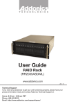
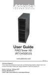
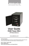
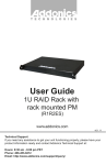
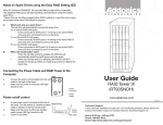
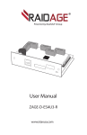
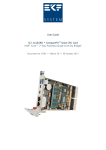
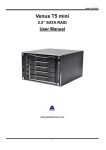
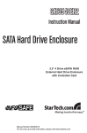
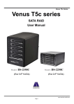
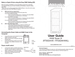
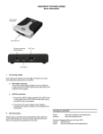
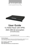
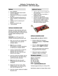
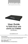
T E C H N O L O G I E S
User Guide
RAID Rack
(RR2035RSDMS)
www.addonics.com
v8.1.11
Technical Support
If you need any assistance to get your unit functioning properly, please have your
product information ready and contact Addonics Technical Support at:
Hours: 8:30 am - 6:00 pm PST
Phone: 408-453-6212
Email: http://www.addonics.com/support/query/
Array 1
Array 3
Array 2
Front
Power Switch
System Reset
Back
Buzzer Reset
Array 4
Fans
LED Display
Redundant Power Supply
Mini SAS Connector
Power Switch: This is the switch to power on devices connected to the power
supply. The power LED will light up to indicate power is supplied.
Note: The main power switch located at the back of the enclosure must be turned
on first.
Reset Button: Not operational.
Buzzer Reset: Pressing the button stops the overheat buzzer from making a sound.
The buzzer will make a sound when temperature inside the storage rack exceeds the
temperature setting on the Thermal Management card.
Note: Buzzer reset switch does not silence the port multiplier buzzer.
Power LED: Lights up when the power switch is turned on.
Temp LED: Lights up when temperature setting inside the storage rack exceeds
the setting on the thermal card.
Fan LED: Normally on when fan is operational. If an abnormal condition is
detected, the LED flashes.
HDD LED: Not operational.
www.addonics.com
Technical Support (M-F 8:30am - 6:00pm PST)
Phone: 408-453-6212
Email: www.addonics.com/support/query/
RAID Rack with Port Multiplier Compatibility
Note: When configured as a set of individual drives, the Port Multiplier
will only work with a Port Multiplier aware host. Identify your host controller and check with its hardware manufacturer if you are unsure. Addonics
offers several Port Multiplier capable host adapters.
Power Supply and Host Connection
The redundant power supply provides 500W of power. Before turning on
the main switch located on the front panel of the RAID Rack, connect and
switch on both units in this power supply. If only one power supply is
running, an audible alarm will sound.
Connect the unit to a computer using the provided mini SAS cable before
powering up the RAID Rack.
www.addonics.com
Technical Support (M-F 8:30am - 6:00pm PST)
Phone: 408-453-6212
Email: www.addonics.com/support/query/
Installing drives into the RAID Rack
1. Be sure the lock on each drive door is in an unlock position. If not, use the key
that comes with the Disk Array to unlock the drive door. Pull on the door lever to
swing open the drive door all the way.
2. Slide a 3.5” SATA hard drive into the drive slot with the drive connector side
facing in. Be sure to orient the hard drive correctly as shown in the yellow label
on the inside of the drive door – with drive door swing open at the bottom, the
top of the hard drive should face to the right. The drive should slide all the way
into the slot with very little resistance. Forcing the drive into the slot will cause
drive damage or permanent damage to the Disk Array.
3. Once the drive is all the way into the drive slot, close the door all the way till the
drive door latch securely. This will engage power and data connection with the
hard drive. The LED lit for the drive slot should lit if the Disk Array already
powered on. You may lock the drive door with the key.
4. To remove the hard drive from the Disk Array, simply follow the step 2 – 3 in
reverse.
Insert hard drives
with top facing right
Door lock
Individual drive
bay door
Power & Activity LED for
each drive bay
Main Power LED
for each array
www.addonics.com
Technical Support (M-F 8:30am - 6:00pm PST)
Phone: 408-453-6212
Email: www.addonics.com/support/query/
Top Cover Screws
How to Remove the Top Cover:
1.
2.
3.
Locate the 2 screws at the back of the
storage rack
Turn screws counterclockwise to
loosen.
Lift the top cover and pull towards the
rear end of the rack.
To Mount Back the Top Cover:
1.
2.
O
I
O
I
O
I
O
I
3.
Align the top cover with the edges of
the rack.
Lay it flat on the rack and slide it
towards the front of the rack.
Turn screws clockwise to tighten.
www.addonics.com
Technical Support (M-F 8:30am - 6:00pm PST)
Phone: 408-453-6212
Email: www.addonics.com/support/query/
Thermal Management Card on the RAID Rack*
Fan Connectors
Overheat Buzzer
Floppy Power Connector
Ambient Detect Terminal
Temp. Setting
(40°C, 50°C, 60°C)
Fan, Temperature and Power LED Connectors
Fan Detect Selection
Fan1 to Fan8 could be set either “ENABLE” or “DISABLE”. When all the fans are set
on “DISABLE”, the Fan LED will have no light on.
*The Thermal management card in the RR2035ASDES is pre-configured. This diagram is for reference only.
www.addonics.com
Technical Support (M-F 8:30am - 6:00pm PST)
Phone: 408-453-6212
Email: www.addonics.com/support/query/
Resetting the RAID Mode
NOTE: This procedure destroys all RAID data. It should not harm individual
drives or their contents; however, creating or running backups of all data is
strongly recommended before proceeding.
1. Power down the unit and set the dip switch to the factory default setting (all
switches OFF).
2. While holding the SET button with a ballpoint pen, turn the unit on. A long
beep will sound from the Port Multiplier. The SET button may be released
once the long beep stops.
Setting or Modifying the RAID Mode
NOTE: Setting or modifying the RAID mode destroys all data.
1. Follow the procedure for resetting the RAID Mode.
2. Power down the unit and set the dip switch to the desired RAID Mode.
3. While holding the SET button with a ballpoint pen, turn the unit on. A long
beep will sound from the Port Multiplier. The SET button may be released
once the long beep stops.
If instead of a long beep the Port Multiplier sounds a series of short beeps, an
error has occurred during configuration of the array.
Windows users may install the JMicron HW RAID Manager application
located on the SATA Controller CD. In the CD, browse to Configuration
Utilities → JMB393. The JMicron HW RAID Manager can be used to create,
modify, and monitor the health status of the RAID drives, and provide status
alerts. When configuring the RAID mode using the RAID Manager application,
it is strongly recommended to leave the dip switch in the factory default
setting.
Using identical drives for all settings other than JBOD or LARGE is strongly
recommended. Creating a LARGE array using drives that have different
properties will use all space on all members, and performance will match that
of the member in use during any particular I/O operation. Creating a RAID
using drives that are not all the same size will result in all members using only
as much space as the smallest member. Creating a RAID using drives that
have different performance will degrade the overall performance of the array.
www.addonics.com
Technical Support (M-F 8:30am - 6:00pm PST)
Phone: 408-453-6212
Email: www.addonics.com/support/query/
BZS Switch (SW1:1):
The BZ switch is used to silence the audible alarm buzzer. The OFF position
permits the audible alarm, and the ON position silences the audible alarm.
The BZ switch has immediate effect.
EZ Switch (SW1:2):
The EZ (spare) switch inhibits spares when ON. When in the OFF position,
all individual drives (not defined as members of an array) are considered
spare. Should a RAID become degraded, when the EZ switch is in the OFF
position a spare drive will be used automatically to rebuild the RAID, if
present. EZ mode is determined when the unit is powered up. Changing the
switch will have no effect until the unit has been re-powered.
RAID Mode Switches M2, M1, M0 (SW1:3 – SW1-5)
The RAID Mode switches define what type of RAID will be initialized when
the unit is powered up while the RAID Mode button is held down. Each type
of RAID has different properties and requirements, as follows:
Raid Mode
BZS1
EZ
M2
M1
M0
JBOD (Individual
drives)
OFF
OFF2
OFF
OFF
OFF
OFF
OFF
OFF
OFF
OFF
OFF
ON3
OFF
OFF
OFF
OFF
ON3
ON
ON
ON
OFF
OFF
ON
ON
ON
ON
ON
ON
OFF
ON
OFF
OFF
OFF
ON
ON
* FACTORY DEFAULT
SETTING
0
1 or 10
3
5
CLONE
LARGE
1 Audible alarm is recommended at all times.
2 EZ mode has no effect in JBOD mode.
3 Disabling EZ for RAID 0 and LARGE is strongly recommended.
www.addonics.com
Technical Support (M-F 8:30am - 6:00pm PST)
Phone: 408-453-6212
Email: www.addonics.com/support/query/
JBOD Mode (Individual Drives)
Number of drives: at least 1
Unit capacity: N/A (100% of each individual drive)
Spares: no
Fault tolerance: none
JBOD mode offers all connected units to the host adapter, no RAID is
defined at all.
NOTE: JBOD mode requires a SATA controller featuring Port Multiplier
support for eSATA connections.
NOTE: Optical drives can only be configured as JBOD using an eSATA
connection.
RAID 0 (Stripe set)
Number of drives: at least 2
Unit capacity: size of each member times number of members.
Spares: no
Fault tolerance: none - if any member is lost all data is lost.
RAID 0 “stripes” the file system across the array by placing sectors of data
sequentially between drives in a specific order.
RAID 1 or 10 (Mirror set, Stripe of mirror sets)
Number of drives: 2 (RAID 1) or 4 (RAID 10).
Unit capacity: size of one member (RAID 1) or size of two members (RAID
10).
Spares: yes – if EZ mode is not disabled and 3 (RAID 1) or 5 (RAID 10)
drives are present, the array will be initialized with a spare.
Fault tolerance: RAID 1 can withstand the loss of one drive without losing
data. RAID 10 can withstand the loss of one drive from each mirror set
without losing data.
RAID 1 works by duplicating the exact same data on two drives.
RAID 10 works by using two RAID 1 sets configured as members of a RAID
0. Disks 1 and 2 are mirrored, disks 3 and 4 are mirrored, and the two mirror
sets are striped together.
www.addonics.com
Technical Support (M-F 8:30am - 6:00pm PST)
Phone: 408-453-6212
Email: www.addonics.com/support/query/
RAID 3 (Stripe set with dedicated parity)
Number of drives: at least 3
Unit capacity: size of one member times number of members minus one.
Spares: yes
Fault tolerance: can withstand the loss of one drive without losing data.
RAID 3 works by striping data for individual I/O blocks across all members
except one, which contains parity data for the stripe set computed by the
Port Multiplier.
RAID 5 (Stripe set with striped parity)
Number of drives: at least 3
Unit capacity: size of one member times number of members minus one.
Spares: yes
Fault tolerance: can withstand the loss of one drive without losing data.
RAID 5 works by striping entire I/O blocks across all members of the set,
with each member taking turns carrying parity data computed by the Port
Multiplier.
CLONE (Mirror set)
Number of drives: at least 2
Unit capacity: size of one member.
Spares: yes
Fault tolerance: can withstand the loss of any number of drives without
losing data as long as at least one complete member remains online.
CLONE mode works the same way as RAID 1, by maintaining a complete
copy of the entire set of data on each drive.
LARGE (Spanned set)
Number of drives: at least 2
Unit capacity: 100% of all drives together regardless of differences in size
Spares: no
Fault tolerance: cannot withstand the loss of any drives without losing data.
However, some data may be recovered as long as the drive(s) carrying the
file system data (boot record, directory, etc.) remain online.
LARGE mode is neither a RAID nor is it a JBOD. It works by declaring the
sum of all available space of the member drives as a single unit, without
striping the data. As each member is filled, new data is stored on the next.
www.addonics.com
Technical Support (M-F 8:30am - 6:00pm PST)
Phone: 408-453-6212
Email: www.addonics.com/support/query/
Notes about Spare Drives
If EZ mode is disabled (SW1:2 ON), all individual drives not configured as
array members will be offered to the host adapter as separate units.
To create an array with one or more spares, set or modify the RAID mode
using fewer than 5 members, while the spares are disconnected from the
Port Multiplier. When EZ mode is enabled, individual drives connected when
an array is present are considered spare.
Spare drives must be equal to or larger in size than the smallest member.
When any type of array is defined, individual units will be considered spare.
RAID 0 and LARGE arrays are not fault-tolerant and spare drives will not be
useful; therefore, disabling EZ for these arrays is recommended.
When a spare drive is present and a fault-tolerant RAID (1, 10, 3, or 5) is
defined, EZ mode will automatically rebuild any available spares into the
array.
www.addonics.com
Technical Support (M-F 8:30am - 6:00pm PST)
Phone: 408-453-6212
Email: www.addonics.com/support/query/
CONTACT US
www.addonics.com
Phone:
Fax:
Email:
408-573-8580
408-573-8588
http://www.addonics.com/sales/query/