1
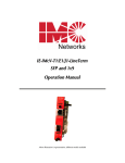
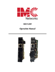
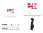
iMcV-Switch
Operation Manual
FCC Radio Frequency Interference Statement
This equipment has been tested and found to comply with the limits for a Class B computing device, pursuant to Part 15 of the FCC Rules.
These limits are designed to provide reasonable protection against harmful interference when the equipment is operated in a commercial
environment. This equipment generates, uses and can radiate radio frequency energy and, if not installed and used in accordance with the
instruction manual, may cause harmful interference to radio communications. Operation of this equipment in a residential area is likely to
cause harmful interference in which the user will be required to correct the interference at his own expense.
Any changes or modifications not expressly approved by the manufacturer could void the user’s authority to operate the equipment.
The use of non-shielded I/O cables may not guarantee compliance with FCC RFI limits. This digital apparatus does not exceed the Class B
limits for radio noise emission from digital apparatus set out in the Radio Interference Regulation of the Canadian Department of
Communications.
Le présent appareil numérique n’émet pas de bruits radioélectriques dépassant les limites applicables aux appareils numériques de classe B
prescrites dans le Règlement sur le brouillage radioélectrique publié par le ministère des Communications du Canada.
Warranty
IMC Networks warrants to the original end-user purchaser that this product, EXCLUSIVE OF SOFTWARE, shall be free
from defects in materials and workmanship under normal and proper use in accordance with IMC Networks' instructions
and directions for a period of six (6) years after the original date of purchase. This warranty is subject to the limitations set
forth below.
At its option, IMC Networks will repair or replace at no charge the product which proves to be defective within such
warranty period. This limited warranty shall not apply if the IMC Networks product has been damaged by unreasonable
use, accident, negligence, service or modification by anyone other than an authorized IMC Networks Service Technician
or by any other causes unrelated to defective materials or workmanship. Any replaced or repaired products or parts carry
a ninety (90) day warranty or the remainder of the initial warranty period, whichever is longer.
To receive in-warranty service, the defective product must be received at IMC Networks no later than the end of the
warranty period. The product must be accompanied by proof of purchase, satisfactory to IMC Networks, denoting
product serial number and purchase date, a written description of the defect and a Return Merchandise Authorization
(RMA) number issued by IMC Networks. No products will be accepted by IMC Networks which do not have an RMA
number. For an RMA number, contact IMC Networks at PHONE: (800) 624-1070 (in the U.S and Canada) or (949) 4653000 or FAX: (949) 465-3020. The end-user shall return the defective product to IMC Networks, freight, customs and
handling charges prepaid. End-user agrees to accept all liability for loss of or damages to the returned product during
shipment. IMC Networks shall repair or replace the returned product, at its option, and return the repaired or new
product to the end-user, freight prepaid, via method to be determined by IMC Networks. IMC Networks shall not be
liable for any costs of procurement of substitute goods, loss of profits, or any incidental, consequential, and/or special
damages of any kind resulting from a breach of any applicable express or implied warranty, breach of any obligation
arising from breach of warranty, or otherwise with respect to the manufacture and sale of any IMC Networks product,
whether or not IMC Networks has been advised of the possibility of such loss or damage.
EXCEPT FOR THE EXPRESS WARRANTY SET FORTH ABOVE, IMC NETWORKS MAKES NO OTHER WARRANTIES,
WHETHER EXPRESS OR IMPLIED, WITH RESPECT TO THIS IMC NETWORKS PRODUCT, INCLUDING WITHOUT
LIMITATION ANY SOFTWARE ASSOCIATED OR INCLUDED. IMC NETWORKS SHALL DISREGARD AND NOT BE
BOUND BY ANY REPRESENTATIONS OR WARRANTIES MADE BY ANY OTHER PERSON, INCLUDING EMPLOYEES,
DISTRIBUTORS, RESELLERS OR DEALERS OF IMC NETWORKS, WHICH ARE
INCONSISTENT WITH THE WARRANTY SET FORTH ABOVE. ALL IMPLIED WARRANTIES INCLUDING THOSE OF
MERCHANTABILITY AND FITNESS FOR A PARTICULAR PURPOSE ARE HEREBY LIMITED TO THE DURATION OF THE
EXPRESS WARRANTY STATED ABOVE.
Every reasonable effort has been made to ensure that IMC Networks product manuals and promotional materials
accurately describe IMC Networks product specifications and capabilities at the time of publication. However, because of
ongoing improvements and updating of IMC Networks products, IMC Networks cannot guarantee the accuracy of printed
materials after the date of publication and disclaims liability for changes, errors or omissions.
ii
Table of Contents
FCC Radio Frequency Interference Statement ....................................................ii
Warranty............................................................................................................ii
About the iMcV-Switch ......................................................................................1
Installing the iMcV-Switch ..................................................................................1
Unmanaged Modules.........................................................................................2
Specifications .....................................................................................................6
Fiber Optic Cleaning Guidelines.........................................................................7
Electrostatic Discharge Precautions.....................................................................7
IMC Networks Technical Support.......................................................................8
Certifications......................................................................................................8
iii
About the iMcV-Switch
The iMcV-Switch is a 5-port Ethernet module that allows the user to increase the port
density and service area of Ethernet networks. The store and forward switch function
allows the user to extend Ethernet service to locations a total of 100 meters from the
Ethernet source. All RJ-45 ports Auto Negotiate 10/100BaseT, full/half duplex, and
automatically configure for MDI or MDIX operation. Each port allows a maximum
frame size of up to 1916 bytes, with support for Flow Control and priority queuing.
Each SFP or fixed fiber port supports 100 Mbps FDX; the fiber is available in a variety
of SM and MM types, including SSF.
Priority Queuing
The iMcV-Switch supports two levels of priority queuing at the egress of every port.
All frames with high priority will egress the port ahead of low priority frames at a 10:1
ratio. Priority is determined, first, through VLAN Tag priority. If no VLAN Tag is
available then the DiffServ (ToS) bits are used. The VLAN Tag priority is based on a 3
bit PRI word where the base priority is set to “4”. Values of 4 or greater have high
priority.
Flow Control
Flow Control is based on the outcome of the Auto Negotiate function. If Flow
Control is enabled then a port will stop transmitting frames when a PAUSE frames is
received. When the internal buffers become congested the unit will send PAUSE
frames to all congested ports. Frames will be dropped if no internal buffer space is
available at ingress.
Installing the iMcV-Switch
The iMcV-Switch is a media converter module that provides 5-port 10/100 Auto
Negotiating Ethernet ports. The module can be installed in any iMediaChassis,
MediaChassis or IE-MediaChassis series.
Managed Modules
In order to manage an iMcV-Switch, an SNMP agent must be present in the chassis.
To manage the module, first install the module into the chassis. After installing IMC
Network’s free SNMP software, iView², port status per port can be monitored. There
is no port configuration; the Graphical User Interface (GUI) provides LED status
information only. SFP’s with DDMI will not offer an SFP Table through iView².
1
Unmanaged Modules
The iMcV-Switch is an unmanaged 5-port 10/100 module; there are no DIP Switch
settings to configure. If installed in an unmanaged chassis, the LEDs will indicate the
status of each port.
Port LEDs
The ports on the iMcV-Switch include diagnostic LEDs that indicate unique
information about the port functionality and status.
iMcV-Switch TX/5
For all units with 5 copper ports, the two LEDs associated with each twisted pair port
are defined as follows:
Port
LED
Name
LNK/ACT
TX
FDX
Color
Function
OFF
GREEN
Flash GREEN
OFF
GREEN
Flash GREEN
No link signal detected on copper port
Copper port is receiving sync signal
Activity is detected on the port
Port is operating in half duplex
Port is operating in full duplex
Flashes when port is set to HDX and collisions occur
2
iMcV-Switch TX/4 + SFP
For all units with 4 copper ports, the two LEDs associated with each twisted pair port
are defined as follows:
Port
LED
Name
LNK/ACT
TX
FDX
FX
LNK/ACT
Color
Function
OFF
GREEN
Flash GREEN
OFF
GREEN
Flash GREEN
OFF
GREEN
Flash GREEN
No link signal detected on copper port
Copper port is receiving sync signal
Activity is detected on the port
Port is operating in half duplex
Port is operating in full duplex
Flashes when port is set to HDX and collisions occur
No SFP installed
Glows green when Link is established
Flashes GREEN w/Activity
3
iMcV-Switch TX/3 + 2SFP
For all units with 3 copper ports, the two LEDs associated with each twisted pair port
are defined as follows:
Port
LED
Name
LNK/ACT
TX
FDX
FX
SFP
A
FX
SFP
B
LNK/ACT
LNK/ACT
Color
Function
OFF
GREEN
Flash GREEN
OFF
GREEN
Flash GREEN
OFF
GREEN
Flash GREEN
OFF
GREEN
Flash GREEN
No link signal detected on copper port
Copper port is receiving sync signal
Activity is detected on the port
Port is operating in half duplex
Port is operating in full duplex
Flashes when port is set to HDX and collisions occur
No SFP installed
Glows green when Link is established
Flashes GREEN w/Activity
No SFP installed
Glows green when Link is established
Flashes GREEN w/Activity
4
iMcV-Switch-TX/3 + FX
For all units with 3 copper ports, the two LEDs associated with each twisted pair port
are defined as follows:
Port
LED
Name
LNK/ACT
TX
FDX
FX
LNK/ACT
Color
Function
OFF
GREEN
Flash GREEN
OFF
GREEN
Flash GREEN
OFF
GREEN
Flash GREEN
No link signal detected on copper port
Copper port is receiving sync signal
Activity is detected on the port
Port is operating in half duplex
Port is operating in full duplex
Flashes when port is set to HDX and collisions occur
No link
Link at 100 Mbps
Activity is detected on the fiber port
5
Specifications
Industry Standards
IEEE 802.3x Ethernet Standards
IEEE 802.3u Auto Negotiation Standards
Ethernet Connections: 10/100 BaseT, Auto Negotiation, AutoCross, Flow Control,
1916 MTU, Full Line - Rate Forwarding
Power Consumption (typical)
TX/5
0.19A @ 5V
TX/4 + SFP
0.57A @ 5V
TX/3 + 2SFP
0.6 5A @ 5V
TX/3 + FX
0.444A @ 5 V
Operating Temperature
32° to 122° F (0° to 50° C)
Operating Power
2.5W
Storage Temperature
-31° to 158° F (-35° to 70° C)
Humidity
5 to 95% (non-condensing); 0 to 10,000 ft. altitude
Dimensions
4.19” x .78” x 2.75” (106.4 mm x 19.81mm x 69.85 mm)
6
Fiber Optic Cleaning Guidelines
Fiber Optic transmitters and receivers are extremely susceptible to contamination by
particles of dirt or dust, which can obstruct the optic path and cause performance
degradation. Good system performance requires clean optics and connector ferrules.
1.
Use fiber patch cords (or connectors, if you terminate your own fiber) only from
a reputable supplier; low-quality components can cause many hard-to-diagnose
problems in an installation.
2.
Dust caps are installed at IMC Networks to ensure factory-clean optical devices.
These protective caps should not be removed until the moment of connecting
the fiber cable to the device. Should it be necessary to disconnect the fiber
device, reinstall the protective dust caps.
3.
Store spare caps in a dust-free environment such as a sealed plastic bag or box
so that when reinstalled they do not introduce any contamination to the optics.
4.
If you suspect that the optics have been contaminated, alternate between
blasting with clean, dry, compressed air and flushing with methanol to remove
particles of dirt.
Electrostatic Discharge Precautions
Electrostatic discharge (ESD) can cause damage to any product, add-in modules or
stand alone units, containing electronic components. Always observe the following
precautions when installing or handling these kinds of products
1.
Do not remove unit from its protective packaging until ready to install.
2.
Wear an ESD wrist grounding strap before handling any module or component.
If the wrist strap is not available, maintain grounded contact with the system unit
throughout any procedure requiring ESD protection.
3.
Hold the units by the edges; do not touch the electronic components or gold
connectors.
4.
After removal, always place the boards on a grounded, static-free surface, ESD
pad or in a proper ESD bag. Do not slide the modules or stand alone units over
any surface.
WARNING! Integrated circuits and fiber optic components are
extremely susceptible to electrostatic discharge damage. Do not
handle these components directly unless you are a qualified service
technician and use tools and techniques that conform to accepted
industry practices.
7
IMC Networks Technical Support
Tel: (949) 465-3000 or (800) 624-1070 (in the U.S. and Canada);
+32-16-550880 (Europe)
Fax: (949) 465-3020
E-Mail: [email protected]
Web: www.imcnetworks.com
Certifications
CE: The products described herein comply with the Council Directive on
Electromagnetic Compatibility (2004/108/EC).
Class 1 Laser product, Luokan 1 Laserlaite,
Laser Klasse 1, Appareil A’Laser de Classe 1
European Directive 2002/96/EC (WEEE) requires that any equipment that bears this
symbol on product or packaging must not be disposed of with unsorted municipal
waste. This symbol indicates that the equipment should be disposed of separately
from regular household waste. It is the consumer’s responsibility to dispose of this
and all equipment so marked through designated collection facilities appointed by
government or local authorities. Following these steps through proper disposal and
recycling will help prevent potential negative consequences to the environment and
human health. For more detailed information about proper disposal, please contact
local authorities, waste disposal services, or the point of purchase for this equipment.
8
19772 Pauling • Foothill Ranch, CA 92610-2611 USA
TEL: (949) 465-3000 • FAX: (949) 465-3020
www.imcnetworks.com
© 2009 IMC Networks. All rights reserved.
The information in this document is subject to change without notice. IMC Networks assumes no responsibility for any
errors that may appear in this document. iMcV-Switch is a trademark of IMC Networks. Other brands or product names
may be trademarks and are the property of their respective companies.
Document Number 52-80445-01 A0
December 2009