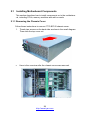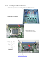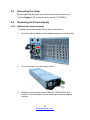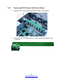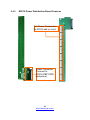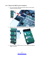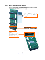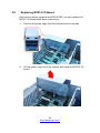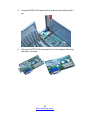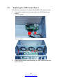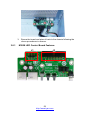
1
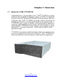
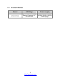
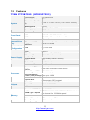
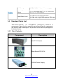
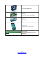
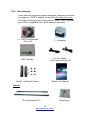
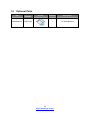
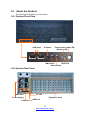
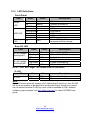
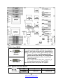
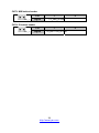
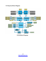
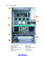
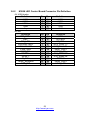
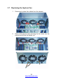
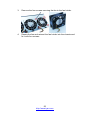
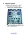
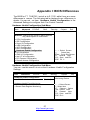
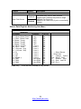
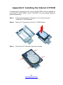
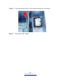
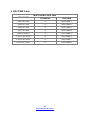
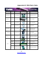
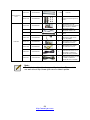
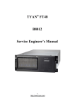
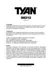
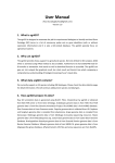
TYAN® FT72
B7015
Service Engineer’s Manual
1
http://www.tyan.com
2
http://www.tyan.com
PREFACE
Copyright
This publication, including all photographs, illustrations, and software, is
protected under international copyright laws, with all rights reserved.
Neither this manual, nor any material contained herein, may be
reproduced without written consent of manufacturer.
Copyright 2009 MiTAC International Corporation. All rights reserved.
®
TYAN is a registered trademark of MiTAC International Corporation.
Version 1.00
Disclaimer
Information co ntained in th is docume nt is furnis hed b y Mi TAC Computer
Corporation a nd h as be en r eviewed for accuracy a nd r eliability prior to
®
printing. T YAN assumes no li ability whatsoever, an d disclaims a ny
®
express or implied warranty, relating to sale and/or use of T YAN products
including liability or warranties relating to fitness for a partic ular purpose or
®
merchantability. T YAN retains the right to make cha
nges to prod uce
descriptions and/or sp ecifications at a ny ti me, without no tice. In no ev ent
®
will T YAN b e held li able for any dir ect or indirect, incide
ntal or
consequential damage, loss of use, lo ss of data or other malady resulting
from errors or inaccuracies of information contained in this document.
Trademark Recognition
All registered and unregistered trademarks and company names contain-ed in this manual are property of their respective owners including, but not
limited to the following.
®
TYAN is a trademark of MiTAC Computer Corporation.
®
Intel is a trademark of Intel Corporation.
®
®
AMI , AMIBIOS and combinations thereof are trademarks of AMI
Technologies.
®
®
Microsoft , Windows are trademarks of Microsoft Corporation.
®
Winbond is a trademark of Winbond Electronics Corporation.
Portable Document Format (PDF) is a trademark of Adobe Corporation.
3
http://www.tyan.com
Federal Communication Commission (FCC)
Notice for the USA
Compliance Information Statement (Declaration of
Conformity Procedure) DoC FCC Part 15: This
device complies with part 15 of the FCC Rules
Operation is subject to the following conditions:
1)
This device may not cause harmful interference;
2)
This device must accept an
y interference re ceived i ncluding
interference that may cause undesired operation. If this equipment
does ca use harmful interfer ence to ra dio or televis ion r eception,
which can be determined by turning the equipment off and on, the
user is encouraged to try one or more of the following measures:
– Reorient or relocate the receiving antenna.
– Increase the separation between the equipment and the receiver.
– Plug the equipment into an outlet on a circuit different from that of
the receiver.
Consult the dealer on an experienced radio/television technician for
help.
Notice for Canada
This apparatus complies with the Class A limits for radio interference as
specified in the Can adian Depar tment of Communic ations Ra dio
Interference R egulations. (Cet appar eil es t conforme au x norms d e
Classe A d’interference radio tel que specifie par le Min istere Canadien
des Communications dans les reglements d’ineteference radio.)
Notice for Europe (CE Mark)
This product is in conformity with the Council
Directive 89/336/EEC, 92/31/EEC (EMC).
CAUTION: Lit hium b attery included with t his bo ard. D o not pu ncture,
mutilate, or dispose of battery in fire. There will be danger of explosion if
battery is incorrectly replaced. Replace only with the same or equivalent
type recommended by manufacturer. Dispose of used battery according
to manufacturer instructions and in accordance with your local regulatio-ns.
4
http://www.tyan.com
About this Manual
This manual provides you with instructions on installing your
FT72-B7015. This Manual is intended for experienced users and
integrators with hardware knowledge of personal computers.
This manual is consisted of the following parts:
Chapter1:
Provides an introduction to the FT72-B7015 bare-bones, standard parts list, describes the external
components, gives a table of key components,
and provides block diagrams of the system.
Chapter2:
Covers procedures on installing the CPU, memory
modules, add on card and hard drives.
Chapter3:
Covers removal and replacement procedures for
pre-installed components.
Appendix :
Describes the differences between motherboard
BIOS and system BIOS; introduces how to install
the internal HDD, list the cable connection and
FRU part tables for reference of system setup;
and technical support in case a problem arises
with your system.
For information on the mainboard, please refer to the attached
mainboard user’s manual. You can find the detailed description
about jumper and BIOS settings from the mainboard manual.
5
http://www.tyan.com
SAFETY INFORMATION
Before instal ling and us ing FT 72-B7015, take note of the follo
precautions:
wing
·Read all instructions carefully.
·Do not place the unit on an unstable surface, cart, or stand.
·Do not bloc k the slots and ope ning on the unit, which are provid ed for
ventilation.
·Only use the power source indicated on the marking label. If you are not
sure, contact the power company.
·The unit uses a three-wire ground cable, which is equipped with a third pin
to ground the unit and prevent electric shock. Do not defeat the pur-pose of this pin. If you outlet does not support this kind of plug, contact
your electrician to replace your obsolete outlet.
·Do not place anything on the power cord. Place the power cord where it will
not be in the way of foot traffic.
·Follow all warnings and cautions in this manual and on the unit case.
·Do not push objects in the ventilation slots as they may touch high volta-ge components and result in shock and damage to the components.
·When replacing parts, ensure that you use parts specified by the manuf-acturer.
·When service or repairs have been done, perform routine safety checks
to verify that the system is operating correctly.
·Avoid usi ng the s ystem ne ar water, in dir ect sunlig ht, or near a heatin g
device.
·Cover the unit when not in use.
6
http://www.tyan.com
Table of Contents
Chapter 1: Overview ......................................................................9
1.1 About the TYAN FT72-B7015 ................................................. 9
1.2 Product Models......................................................................10
1.3 Feat ures ................................................................................11
1.4 Standard Parts List ................................................................13
1.4.1 Box Contents ..................................................................13
1.4.2 Ac cessories ....................................................................15
1.5 Optional Parts........................................................................16
1.6 About the Product..................................................................17
1.6.1 Sys tem Front View .........................................................17
1.6.2 Sys tem Rear View ..........................................................17
1.6.3 LED Definitions...............................................................17
1.6.4 Motherboa rd Layout .......................................................19
1.6.5 J umpers & Connectors ...................................................20
1.6.6 Sys tem Block Diagram ...................................................25
1.6.7 Inter nal View...................................................................26
Chapter 2: Setting Up..................................................................27
2.0.1 Before you Begin ............................................................27
2.0.2 Work Area.......................................................................27
2.0.3 T ools ...............................................................................27
2.0.4 Prec autions.....................................................................28
2.1 Installing Motherboard Components .....................................29
2.1.1 Removing the Chassis Cover.........................................29
2.1.2 Ins talling the CPU and Heatsink.....................................30
2.1.3 Ins talling the Memory .....................................................32
2.1.4 Installing Expansion Cards.............................................35
2.1.5 Ins talling Hard Drives .....................................................37
2.2 Rack Mounting.......................................................................38
2.2.1 Ins talling the Server in a Rack........................................38
2.2.2 Ins talling the inner Rails to the Chassis .........................39
2.2.3 Ins talling the Outer Rails to the Rack .............................40
2.2.4 Rack mounting the Server..............................................40
Chapter 3: Replacing Pre-Installed Components .....................43
3.1 Intr oduction............................................................................43
3.2 Dis assembly Flowchart..........................................................43
7
http://www.tyan.com
3.3 Removing the Cover..............................................................44
3.4 Replaci ng the Power Supply .................................................44
3.4.1 Replac e the power supply ..............................................44
3.4.2 Replacing M7015 Power Distribution Board ..................45
3.4.3 M7015 Power Distribution Board Features ....................46
3.4.4 Replac e the M7015 power backplane ............................47
3.4.5 M7015 power backplane Features .................................48
3.5 Replac ing M7015 I/O Board ..................................................49
3.6 Replac ing the LED Control Board .........................................51
3.6.1 M1008 LED Control Board Features ..............................52
3.6.2 M1008 LED Control Board Connector Pin Definition .....53
3.7 Replac ing the System Fan ....................................................54
3.8 Removing the Motherboard...................................................56
Appendix I: BIOS Differences.....................................................57
Appendix II: Installing the Internal 3.5”HDD..............................59
Appendix III: Cable Connection Tables .....................................61
Appendix IV: FRU Parts Table ....................................................63
Appendix V: Technical Support .................................................65
8
http://www.tyan.com
Chapter 1: Overview
1.1
About the TYAN FT72-B7015
®
Congratulations on your purc hase of the T YAN FT 72-B7015, a hig hly
optimized rack-mountable 4U barebone system. FT72-B7015 is designed
®
to support dual Intel Nehalem-EP/Nehalem-WS 2S processors and up to
6 cha nnels with 18 DD R3 DIMMs, provid ing a rich fe ature set an d
®
incredible perf ormance. Leverag ing adv anced techno logy from Intel ,
FT72-B7015 server s ystem is capable of offering scal able 32 and 64-b it
computing, high-bandwidth memory design, and l ightning-fast PCI-E bus
implementation. FT72-B7015 not only enpowers your company in today’s
demanding IT environm ent but also offers a smooth path for future
application usage.
FT72-B7015 uses rack-mountable 4U chassis featuring a robust structure
and a soli d mecha nical encl osure. All of this provi des F T72-B7015 the
power and flexibility to meet the needs of nearly any server application.
9
http://www.tyan.com
1.2
Product Models
Model
HDD Bays
Power supply
B7015F72V2
Support 2 internal 2.5”
SATAII HDD
2400W(1200W+1200W)
PWR supply
10
http://www.tyan.com
1.3
Features
TYAN FT72B7015 (B7015F72V2)
System
Front Panel
Internal Drive
Bay
Form Factor
Chassis Model
Dimension (D x W x
H)
Motherboard
Board Dimension
Gross Weight
Buttons
LEDs
I/O Ports
Type / QTY
Supported HDD
Interface
4U Rackmount
FT72
27.96" x 17.245" x 6.93" (710 x 438 x 176mm)
S7015
16"x19" (406.4x482.6mm)
32KG
(1) PWR / (1) RST / (1) NMI / (1) ID
(1) PWR / (1) HDD / (1) Warning
(2) USB ports
(2) 2.5" fixed [ or (1) 3.5" fixed, optional ]
SATA-II 3.0Gb/s
System Cooling
FAN
(3) 12cm fans
Configuration
Type
ERP1U
Input Range
Full-range AC(100-240V)
Frequency
60 Hertz
Power Supply Output Watts
2400 Watts(1200W+1200W)
Efficiency
PFC
Redundancy
2+1(Optional)
Serviceability
Hot-swap
Supported CPU
Intel Xeon Processor 5500 Series
Series
Socket Type / QTY LGA1366 / (2)
Processor
Thermal Design
Max up to 130W
Power (TDP) wattage
Up to 4.8/ 5.86/ 6.4GT/s with Intel Quick Path
System Bus
Interconnect (QPI) support
IOH / ICH
Intel (2) 5520 / ICH10R
Chipset
Super I/O
Winbond W83627
PCI-E Switch
PLX PEX8647
Supported DIMM Qty (9)+(9) DIMM slots
DDR3 800/1066/1333* RDIMM/UDIMM / * limit 1
DIMM Type / Speed
per channel for 1333MHz speed
Memory
Capacity
Up to 144GB at launch w/ dual rank RDIMMs
Memory channel
3 Channels per CPU
Memory voltage
1.5V
11
http://www.tyan.com
Expansion Slots PCI-E
Port QTY
LAN
Controller
Connector type
Graphic
Resolution
Chipset
USB
I/O Ports
VGA
RJ-45
Chipset
Voltage
System
Monitoring
Temperature
LED
Onboard Chipset
Server
Management
AST2050 IPMI
Feature
AST2050 iKVM
Feature
Brand / ROM size
BIOS
Operating
System
Regulation
Operating
Environment
RoHS
Package
Contains
Feature
(8) PCI-E Gen.2 x16 slots
(4)
Intel 82574L
D-Sub 15-pin
1600x1200
Aspeed AST2050
(2) ports
(1) D-Sub 15-pin port
(4) ports
Winbond W83793G
Monitors voltage for CPU, memory, chipset &
power supply
Monitors temperature for CPU & system
environment
Fan fail LED indicator / Over temperature
warning indicator
Onboard Aspeed AST2050
IPMI 2.0 compliant baseboard management
controller (BMC) / BIOS update / USB 2.0 virtual
hub
24-bit high quality video compression / Dual
10/100 Mb/s MAC interfaces
AMI / 4MB
Plug and Play (PnP) /PCI2.3 /WfM2.0
/SMBIOS2.3 /PXE boot / ACPI 2.0 power
management /Power on mode after power
recovery / User-configurable H/W monitoring
OS supported list
Please refer to our OS supported list.
FCC (DoC)
CE (DoC)
Operating Temp.
Non-operating
Temp.
In/Non-operating
Humidity
RoHS 6/6 Complaint
Barebone
Manual
Installation CD
Heatsink / Cooler
Class A
Yes
0° C ~ 55° C (32° F~ 131° F)
- 40° C ~ 70° C (-40° F ~ 158° F)
90%, non-condensing at 35° C
Yes
(1) F72-B7015 Barebone
(1) BB User's manual
(1) TYAN installation CD
(2) CHSK-0410, 1366-pin CPU heatsinks
12
http://www.tyan.com
Rail kit
Mounting Ear
Package
Contains
Others
Cable/Power Cord
1.4
(1) CRAL-0150, sliding rail kit
(1) CEAR-0150, mounting ear kit for FT72
(1) 2.5" HDD screw pack / (1) 3.5" HDD screw
pack +(1) 3.5" HDD bracket
(2) CCBL-0312, US type power cord /
(2) CCBL-0313, EU type power cord
(8) CCBL-146I, 2*4pin PWR cable for GPU card
(8) CCBL-146H,2*3pin PWR cable for GPU card
Standard Parts List
This section describ
es FT72-B7015 package co ntents an d
accessories. Open th e box carefully and ensure that all components
are present and undamaged. The product should arrive packaged as
illustrated below.
1.4.1 Box Contents
Component
Description
4U FT72 Chassis
Main Board,S7015-CA
1200W Power Supply
13
http://www.tyan.com
120 x120 x38 MM Fan
M1008
Front LED control Board(R02)
M7015
Rear I/O Board
M7015-PBP
PWR Backplane Board(R01)
M7015-PDB
PWR Distribution board for PCI-E
card(R01)
14
http://www.tyan.com
1.4.2 Accessories
If any items are missing or appear damaged, contract your retailer
®
or browse to TYAN ’s website for service: http://www.tyan.com.
®
The Web site also provides information on other TYAN products,
plus FAQs, compatibility lists, BIOS settings, and more.
®
1 x TYAN Motherboard
Drive CD
2 x Heatsink
HDD Screws
Po wer Cables
Left to right: Europe, US
Mounti ng Ears & Screws
Bareb one Manual
Rail Kit
Rail with Bracket x 2
15
http://www.tyan.com
Screw Sack
1.5
Optional Parts
Item
Model
Number
HDD Bracket
CHDT-0120
Picture
Quantity
Description
1
3.5" HDD Bracket
16
http://www.tyan.com
1.6
About the Product
The following views show you the product.
1.6.1 System Front View
USB ports
ID button
Power button (with LED)
Warning LED
NMI button
HDD LED
Reset button
1.6.2 System Rear View
VGA Port
ID LED
Power Supply
LAN Port
Expansion slots
USB Port
17
http://www.tyan.com
1.6.3 LED Definitions
Front Panel
LED
State
Power
LED
HDD LED
Warning
LED
Color
On
Green
On
Amber
Off Off
On
Green
Blinking Green
On Amber
Blinking Amber
Random Green/Amber
On
Rear I/O LED
LED
Red
State
Description
System is turned on
System is turned off
Power off
HDD power on
HDD active
HDD error
HDD rebuild
HDD locate
Fan fail/PSU fail/Over
temperature/Over voltage
Color
Description
On
Green
10Mb/100Mb/1000Mb linked
Blinking Green
10Mb/100Mb/1000Mb activity
Off
Off
No LAN linked
On
Amber
1000Mb linked/ activity
RJ-45 Linkage/
On Green
100Mb linked/activity
Activity(Right)
Off
Off
10Mb mode or No LAN linked
NOTE: “Left” and “Right” are viewed from the rear panel.
RJ-45 Linkage/
Activity(Left)
ID LED
LED
ID LED
State
On
Off
Color
Blue
Off
Description
System identified
System not identified
Note:
Press ID button when the system is AC (Alternating Current) on, then ID LED
will show the system is identified with emitting blue light. Users from remote
site could also activate ID LED by input a few commands in IPMI, detailed
software support please visit http://www.tyan.com for latest AST2050 user
guide.
18
http://www.tyan.com
1.6.4
Motherboard Layout
The diagram is representative of the latest board revision available at the time of
publishing. The board you receive may not look exactly like the above diagram.
19
http://www.tyan.com
1.6.5
Jumpers & Connectors
Jumper/Connector
Function
CN17/CN20
COM port
CN18
Board-to-Board Receptacle connector
CN19
USB header
CN43
Front Panel header
CN36/CN37/CN40
FAN connector
CN101
Clear CMOS
CN61
System Intrusion header
CN73
NMI button header
CN74
ID button header
20
http://www.tyan.com
Jumper Placement
CN40
CN43
CN19
CN20
CN37
CN36
CN18
CN17
CN43: Front Panel header
Pin
1
2
3
4
5
6
7
8
9
10
11
12
13
14
Pin_1
15
Signal
GND
PW_LED+
PW_LEDWLED+
HDD_LED+
GND
PWR_SW#
P3V3_SB
RST_SW#
GND
SDA
SCL
GND
RXD
TXD
21
http://www.tyan.com
CN18: Board-to-Board Receptacle connector
Signal
GND
RED
GND
GREEN
GND
BLUE
GND
HSYNC
VSYNC
GND
DDC_DATA
DDC_CLK
GND
NC
Vcc5_VGA
NC
GND
GND
GND
GND
Pin
1
3
5
7
9
11
13
15
17
19
21
23
25
27
29
31
33
35
37
39
Pin
2
4
6
8
10
12
14
16
18
20
22
24
26
28
30
32
34
36
38
40
Signal
GND
USB0USB0+
GND
USB1USB1+
GND
USB2USB2+
GND
USB3USB3+
GND
NC
Vcc_USB
Vcc_USB
Vcc_USB
Vcc_USB
Vcc_USB
Vcc_USB
CN19: USB header
Pin_1
Pin
1
2
3
4
5
6
7
8
9
10
Signal
GND
PW_LED+
PW_LEDWLED+
HDD_LED+
GND
PWR_SW#
P3V3_SB
RST_SW#
GND
CN36/ CN37/ CN40: FAN connector
Pin
1
2
3
4
5
6
Signal GND P12V TACH PWM GND P12V
22
http://www.tyan.com
CN73
CN61
CN74
CN101
CN101: Clear CMOS
Pin_3
Pin_1
Normal
(Default)
Pin_3
Pin_1
Clear CMOS
You can reset the CMOS settings by using this
jumper if you have forgotten your system/setup
password or need to clear system BIOS setting.
Power off system and disconnect both
power connectors from the motherboard
Put jumper cap back to Pin_1 and Pin_2
(default setting)
Use jumper cap to close Pin_2 and Pin_3
for several seconds to Clear CMOS
Reconnect power and power on system
CN61: System Intrusion header
Pin
Pin_1
1
Signal
GND INT
23
http://www.tyan.com
2
RUDER_N
CN73: NMI button header
Pin
Pin_1
1
Signal
2
FP_NMI_N GND
CN74: ID button header
Pin
Pin_1
1
Signal
ID_BUTTON_N GND
24
http://www.tyan.com
2
1.6.6 System Block Diagram
S7015 Block Diagram
25
http://www.tyan.com
1.6.7
Internal View
⑧
⑤
①
⑥
②
④
⑦
③
①
②
③
④
S7015 Main Board
M7015 -PDB
PWR Distribution board
M1008
Front LED control Board
System Fan
⑤
⑥
Power Cage
M7015 -PBP
PWR Backplane Board
⑦
HDD Bracket
⑧
PCI-E Slot Shield
26
http://www.tyan.com
Chapter 2: Setting Up
2.0.1 Before you Begin
This chapter explains how to install the CPUs, CPU heatsinks,
memory modules, and hard drives. Instructions on inserting add on
cards are also given.
2.0.2 Work Area
Make sure you have a stable, clean working environment. Dust and
dirt can get into com ponents a nd c ause m alfunctions. Us e
containers to keep sma ll co mponents sep arated. Puttin g all smal l
components in separate cont ainers prevent s them from becomi ng
lost. Adeq uate lighti ng a nd proper tools c an prev ent you from
accidentally damaging the internal components.
2.0.3 Tools
The following procedures require only a few tools, including the
following:
z A cross head (Phillips) screwdriver
z A grounding strap or an anti-static pad
Most of the electrical and mechanical connections can be disconne-cted using your fingers. It is recommended that you do not use nee-dlenosed pliers to remove connectors as these can damage the soft
metal or plastic parts of the connectors.
27
http://www.tyan.com
2.0.4
Precautions
Components and electronic circuit b oards can b e d amaged b y
discharges of static electricity. Working on a system that is connected
to a power supply can be extremely dangerous. Follow the guidelines
below to avoid damage to FT72-B7015 or injury to yourself.
z
Ground yourself properly before removing the top cover of the
system. Unpl ug the po wer from the po wer suppl y and the n
touch a safe ly groun ded obj ect to releas e static charge ( i.e.
power supply case). If avail able, wear a gr ounded wrist strap.
Alternatively, d ischarge an y static electric ity by to uching th e
bare metal chassis of the unit case, or th e bare metal body of
any other grounded appliance.
z
Avoid touching motherboard components, IC chips, connectors,
memory modules, and leads.
z
The motherbo ard is pre-i nstalled in the s ystem. W hen
removing th e mo therboard, always pl ace i t o n a g rounded
anti-static surface until you are ready to reinstall it.
z
Hold electronic circuit boards by the edges only. Do not touch
the components on the board unless it is necessary to do so.
Do not flex or stress circuit boards.
z
Leave all components inside the static-proof packaging that
they ship with until they are ready for installation.
z
After replacing optional devices, make sure all screws, springs,
or other sm all parts are in place a nd are n ot left loos e i nside
the case. Metallic p arts or metal flakes c an caus e el ectrical
shorts.
Note:
All connectors are keyed to only attach one way.
All use the correct screw size as indicated in the procedures.
28
http://www.tyan.com
2.1
Installing Motherboard Components
This section describes how to install components on to the motherboa-rd, including CPUs, memory modules and add on cards.
2.1.1 Removing the Chassis Cover
Follow these instructions to remove FT72-B7015 chassis cover.
1.
Thumb two screws on the back side as show in the small diagram.
Then slide the top cover out.
2.
Here is the overview after the chassis cover was removed.
29
http://www.tyan.com
2.1.2
Installing the CPU and Heatsink
Follow the steps below on installing CPUs and CPU heatsinks.
1. Locate the CPU socket.
2. Press the lever and
unlock the CPU socket.
A
3. Lift the C
PU
protection ca p
up and lay the
CPU into th e
socket(A),
ensuring p in1
is correctly
located(B);
30
http://www.tyan.com
B
4. Close the socket cover and press the CPU lever down to secure the
CPU;
5. Place the h eatsink o n top
of the CP U a nd sec ure it
with 4 screws.
31
http://www.tyan.com
2.1.3 Installing the Memory
Follow thes e i nstructions to inst all the me mory mo dules onto the
motherboard.
1. Locate the memory slots on the motherboard.
2.
Press the memory slot locking levers in the direction of the
arrows as shown in the following illustration.
3.
Align the memory module with the slot. When inserted
properly, the memory slot locking levers lock automatically
onto the indentations at the ends of the module.
32
http://www.tyan.com
Note:
1). For the DIMM number please refer to “Chapter 1.6.4 –
Motherboard Layout” for memory installation.
2). Refer to the memory population option table for
recommended memory installation instruction.
3). “√”indicates a populated DIMM slot.
Memory Population Option Table
To achieve the best performance, TYAN® strongly recommended memory
installation configuration as listed below:
1. Single CPU installed (CPU0 Only)
Quantity of memory
DIMM Slot
CPU0 DIMMA 0
CPU0 DIMMA 1
CPU0 DIMMA 2
CPU0 DIMMB 0
CPU0 DIMMB 1
CPU0 DIMMB 2
CPU0 DIMMC 0
CPU0 DIMMC 1
CPU0 DIMMC 2
CPU1 DIMMA 0
CPU1 DIMMA 1
CPU1 DIMMA 2
CPU1 DIMMB 0
CPU1 DIMMB 1
CPU1 DIMMB 2
CPU1 DIMMC 0
CPU1 DIMMC 1
CPU1 DIMMC 2
1
3
6
9
√
√
√
√
√
√
√
√
√
√
√
√
√
√
√
√
√
√
√
33
http://www.tyan.com
2.
Single CPU installed (CPU1 Only)
Quantity of memory
DIMM Slot
CPU0 DIMMA 0
CPU0 DIMMA 1
CPU0 DIMMA 2
CPU0 DIMMB 0
CPU0 DIMMB 1
CPU0 DIMMB 2
CPU0 DIMMC 0
CPU0 DIMMC 1
CPU0 DIMMC 2
CPU1 DIMMA 0
CPU1 DIMMA 1
CPU1 DIMMA 2
CPU1 DIMMB 0
CPU1 DIMMB 1
CPU1 DIMMB 2
CPU1 DIMMC 0
CPU1 DIMMC 1
CPU1 DIMMC 2
3.
1
3
6
9
√
√
√
√
√
√
√
√
√
√
√
√
√
√
√
√
√
√
√
Dual CPU installed (CPU0 & CPU1)
Quantity of memory
DIMM Slot
CPU0 DIMMA 0
CPU0 DIMMA 1
CPU0 DIMMA 2
CPU0 DIMMB 0
CPU0 DIMMB 1
CPU0 DIMMB 2
CPU0 DIMMC 0
CPU0 DIMMC 1
CPU0 DIMMC 2
CPU1 DIMMA 0
CPU1 DIMMA 1
CPU1 DIMMA 2
CPU1 DIMMB 0
CPU1 DIMMB 1
CPU1 DIMMB 2
CPU1 DIMMC 0
CPU1 DIMMC 1
CPU1 DIMMC 2
1
2
6
12
18
√
√
√
√
√
√
√
√
√
√
√
√
√
√
√
√
√
√
√
√
√
√
√
√
√
√
√
√
√
√
34
http://www.tyan.com
√
√
√
√
√
√
√
√
√
2.1.4 Installing Expansion Cards
FT72-B7015 ha s eight expa nsion slots which c an su pport GPU
(Graphic Processing Unit) card. F ollow these instructions to instal l
expansion cards.
1. Locate the expansion slot on the motherboard, unscrew the
bracket from the slot you want to use.
2. Take the brackets out from the slot.
35
http://www.tyan.com
3. Insert the card into the sl ot and secur e it with the sc rews you
removed from the bracket.
4. Conn ect the cabl es bet ween t he e xpansion car d and the po wer
distribution board, the conn ectors you use should match with the
slot you add the card with.
5. Here is the end of the add on card installation.
36
http://www.tyan.com
2.1.5 Installing Hard Drives
The FT 72-B7015 sup ports tw o internal 2. 5” SAT AII hard disks.
Follow these instructions to install a hard drive.
1. Unscre w the 2.5’’ bracket out from the c hassis, p lace a 2.5’ ’
hard drive into the HDD tray and secure it using four flat screws.
2.
Reinsert the HDD bracket i nto the chassi s, secure it with on e
screw and connect both power cable and SATA cable.
37
http://www.tyan.com
2.2
Rack Mounting
After installing the necessary components, FT72-B7015 can be
mounted in a rack using the supplied rack mounting kit.
Rack mounting kit
Rail with Bracket x 2
Mounting Ears x 2
Screw Sack x 1
2.2.1 Installing the Server in a Rack
Follow these instructions to mount the FT72-B7015 into an industry
standard 19” rack.
Note:
Before mou nting FT72-B7015 in a rack, ensure that all
internal comp onents hav e be en installed an d that the unit
has been fully tested. Maintenance can be performed on the
unit while in a rack but it is preferable to install the device in a
fully operational condition.
Screw Sack
A
B
C
Including:
A: M5 Washer------ 8pcs
B:
M5 x 10 ----------8pcs
C: M5 x13 -----------2pcs
38
http://www.tyan.com
2.2.2 Installing the inner Rails to the Chassis
1.
Screw the mounting ear to each side of F T72 as sho wn using 3
screws from the supplied screws kit.
2.
Push the latch key and draw out the inner rails from sliding rails.
3.
Secure inner r ails to both s ides of the c hassis, be sur e th e five
mounting holes are correctly matched.
39
http://www.tyan.com
2.2.3 Installing the Outer Rails to the Rack
Secure the outer rail to the
rack using the rail an d 4 M5
x 10 scre ws with washer for
each side.
2.2.4 Rack mounting the Server
1. Draw out the middle rail till
the latch position.
2. Lift the chassis and then
insert the inner slide rails
into the middle rails.
40
http://www.tyan.com
3. Push the chassis in and pull the latch key (A). Then push the whole
system into the rack (B).
B
A
4. Secure the mountin g ear s of chassis to the rack
screws.
41
http://www.tyan.com
with 2 M5 x 1 3
42
http://www.tyan.com
Chapter 3: Replacing Pre-Installed
Components
3.1
Introduction
This chapter exp lains how to repl ace the pre -installed components,
including the Motherb oard, M1008 front pane l board, M7 015 power
distribution board, M7015 power backplane, system fan, power cage
etc.
3.2
Disassembly Flowchart
The following flowchart outlines the disassembly procedure.
Chassis Cover
Power Cage
M7015-PDB
M7015 PBP
M7015 I/O board
System Fan
M1008 Front Panel Board
System Main board
43
http://www.tyan.com
3.3
Removing the Cover
Before replacing any parts you must remove the chassis cover.
Follow Chapter 2.1.1 to remove the cover of FT72-B7015.
3.4
Replacing the Power Supply
3.4.1 Replace the power supply
To replace the power supply follow these instructions.
1.
Press the tab as shown in the diagram and pull out the power.
2.
Free the power from the power socket.
3.
Replace a new single power (FRU NO: CPSU-0420) and
reinsert it into the power socket following the above steps in
reverse.
44
http://www.tyan.com
3.4.2
Replacing M7015 Power Distribution Board
1. Remove the 2 screws securing M7015-PDB to the bracket.
2. Renew the M7015-PDB and fix it to the chassis following the step
in reverse.
45
http://www.tyan.com
3.4.3
M7015 Power Distribution Board Features
2x4 Power Connectors
for PCI-E add on card
Power Connector
(Connect to
M7015-PBP PWR
backplane)
46
http://www.tyan.com
3.4.4 Replace the M7015 power backplane
1.
Lift out the M7015- PBP bracket after pulling out the power
Supplies and M7015-PDB.
2. Remove the 4 screws securing M7015-PBP to the bracket.
3. Renew the M7015-PBP and fix it to the chassis following the
steps in reverse.
47
http://www.tyan.com
3.4.5
M7015 power backplane Features
M7015-PBP Power backplane support FT72-B7015 with
EMERSON DC1200-3 power supply.
On board PWR Connector * 3
(Vertical, connect to PWR
supply)
PWR Connector
(Right angle, connect to MB)
PWR Connector
(Vertical, connect to
M7015-PDB PWR
distribution board)
48
http://www.tyan.com
3.5
Replacing M7015 I/O Board
After remove power supplies and M7015 PBP, you can replace the
M7015 I/O board follow these instructions.
1.
Remove the power cage from the chassis with four screws.
2.
Lift the power cage out of the chassis and locate the M7015 I/O
board.
49
http://www.tyan.com
3.
Unscrew M7015 I/O board with its bracket and carefully pull it
up.
4.
Renew the M7015 I/O board and fix it to the chassis following
the step in reverse.
50
http://www.tyan.com
3.6
Replacing the LED Control Board
Follow these instructions to replace the M1008 LED control board.
1.
Unplug the cables from the connectors on M1008 and main
board.
A: From M1008
B: From S7015
2.
Remove the three screws securing the LED control board unit
to the chassis.
51
http://www.tyan.com
3. Renew the board and place it back to the chassis following the
above procedures in reverse.
3.6.1
M1008 LED Control Board Features
J1
J3
52
http://www.tyan.com
3.6.2
M1008 LED Control Board Connector Pin Definition
J1: USB Header
Definition
VCC
USB1USB1+
GND
Key
Pin
1
3
5
7
9
Pin
2
4
6
8
10
Definition
VCC
USB2USB2+
GND
GND
Pin
1
3
5
7
9
11
13
15
17
19
21
23
Pin
2
4
6
8
10
12
14
16
18
20
22
24
Definition
J3: SSI
Definition
PW_LED+
KEY
PW_LEDHD/LAN3 LED+
HD/LAN3 LEDPWR_SW+
PWR_SWRESET+
RESETID_SW+
TEMP_SENSER
EXT_INT
53
http://www.tyan.com
VCC
ID_LED+
ID_LEDSYS_FAULT1SYS_FAULT2LAN1_LED+
LAN1_LEDICH_SMBDAT
ICH_SMBCLK
INTRU#
LAN2_LED+
LAN2_LED-
3.7
Replacing the System Fan
1.
Disconnect system fan cables from the chassis.
2.
Remove the three screws securing the fan holder into the
chassis and lift the fan holder out.
]
54
http://www.tyan.com
3.
Remove the four screws securing the fan to the fan holder.
4.
Renew the fan and reinsert the fan holder into the chassis and
fix it with four screws.
55
http://www.tyan.com
3.8
Removing the Motherboard
After removing all of the aforementioned cables, follow these
instructions to remove the motherboard from the chassis.
1.
Remove the heatsinks and processors if installed.
2.
Remove the 14 screws securing the motherboard to the
chassis.
3.
Carefully lift the motherboard from the chassis as S7015 is too
large to lift straight out .Lift the front edge of the board to an angle of
about 45 then slides the whole board out.
56
http://www.tyan.com
Appendix I: BIOS Differences
The BIOS for FT 72-B7015 is simil ar to S 7015 while t here ar e some
differences in menus. T he follo wing tabl e d isplays th ose differences in
details. You can sel ect item Hardware Health Configuration i n the
Advanced Settings to configure Auto Fan Control Function.
Hardware Health Configuration Sub-Menu
Main
Advanced
Advanced Settings
BIOS Setup Utility
PCI/PnP
Boot
Security
Chipset
Exit
WARING: Setting wrong values in below sections
may cause system to malfunction.
CPU Configuration
IDE Configuration
Super IO Configuration
USB Configuration
ACPI Configuration
AHCI Configuration
Hardware Health Configuration
I/O Virtualization
IPMI 2.0 Configuration
Intel VT-d Configuration
PCI Express Configuration
Remote Access Configuration
← → Select Screen
↑↓
Select Item
Enter Go to Sub Screen
F1 General Help
F10 Save and Exit
ESC Ex it
Hardware Health Configuration Sub-Menu
You can use this scree n to vie w the H ardware H ealth C onfiguration
Settings.
BIOS Setup Utility
Main
Advanced
PCI/PnP
Boot
Security
Chipset
Exit
Enables Hardware Health
Hardware Health Configuration
Monitoring Device.
Auto FAN Control
[Enabled]
Hardware Health Event Monitoring
Sensor Data Register Monitoring
57
http://www.tyan.com
← → Select Screen
↑↓ Select Item
+/- Change Option
Tab Select Field
F1 General Help
F10 Save and Exit
ESC Ex it
Feature
Option
Description
Hardware Health Configuration
FAN power duty cycle is auto dynamic
programmed in selected temperature range.
Disabled: Fan Power On
Enabled: Fan Power Duty Cycle is controlled by
Tcontrol.
Disabled
Auto FAN Control
Enabled
Sensor Data Register Monitoring Sub-Menu
BIOS Setup Utility
ID# NAME
0F
11
12
13
14
0A
0B
05
06
04
01
02
03
22
23
24
Advanced
CPU0 Below Tmax
CPU1 Below Tmax
Board Temp1
Board Temp2
Board Temp3
CPU0 Vcore©
CPU1 Vcore
1.5V(near ICH)
1.1V(near IOH)
5V
3.3V
12V
VBattar y
FAN1
FAN2
FAN3
READING
o
: xx C
o
: xx C
o
: xx C
o
: xx C
o
: xx C
: x.xxx V
: x.xxx V
: x.xxx V
: x.xxx V
: x.xxx V
: x.xxx V
: x.xxx V
: x.xxx V
: xxxx RPM
: xxxx RPM
: xxxx RPM
STATUS
OK
OK
OK
OK
OK
OK
OK
OK
OK
OK
OK
OK
OK
OK
OK
OK
Read only. It can not be modified in user mode.
58
http://www.tyan.com
← → Select Screen
↑↓ Select Item
+/- Change Option
Tab Select Field
F1 General Help
F10 Save and Exit
ESC Ex it
Appendix II: Installing the Internal 3.5”HDD
Considering for a multiple choice, the 2.5” SATA HDD could be replaced by
an internal 3.5” SATA HDD in your FT72-B7015. You can c hoose flexibly in
practical application.
Step 1:
Follow the instructions in Chapter 2.1.5 to remove the pre-installed 2.5’’ HDD Bracket;
Step 2:
Place a 3.5’’ hard drive into the 3.5’’ HDD Bracket;
Step 3:
Secure the 3.5” hard drive using four screws;
59
http://www.tyan.com
Step 4: Place the bracket back to the chassis and secure it as below:
Step 5: Connect the data cables.
60
http://www.tyan.com
Appendix III: Cable Connection Tables
1. FP Ctrl & USB Cable
M1008 FP board to S7015 MB
M1008 FP board
Connect to
S7015 MB
J3
→
→
CN43
J1
CN19
2. System Fan Cable
System Fan to S7015 MB
System Fan
Connect to
S7015 MB
System Fan1
→
CN36
System Fan2
→
CN37
System Fan3
→
CN40
3. SATA & SATA PWR Cable
HDD device to S7015 MB
HDD device
Connect to
S7015 MB
SATA cable 1 for HDD1
→
CN14
SATA cable 2 for HDD2
→
CN15
SATA PWR cable for
HDD1 & HDD2
→
PW4
61
http://www.tyan.com
4. GPU PWR Cable
M7015-PDB to GPU Card
M7015-PDB
Connect to
GPU card
PW1 or PW2
→
→
→
→
→
→
→
→
GPU card 1
PW3 or PW4
PW5 or PW6
PW7 or PW8
PW9 or PW10
PW11 or PW12
PW13 or PW14
PW15 or PW16
62
http://www.tyan.com
GPU card 2
GPU card 3
GPU card 4
GPU card 5
GPU card 6
GPU card 7
GPU card 8
Appendix IV: FRU Parts Table
FT72-B7015
Item
Model Number
Motherboard S7015-
Picture
Quantity
Description
411782600066
1M
CCHA-0390
432775400001
1
4U FT72 CHASSIS
CHDT-0110
340765400020
1
Dual 2.5" HDD Bracket
CHDT-0120
340765400019
1
3.5" HDD Bracket
CPSU-0420
471100600034
2
1200W,Power Supply,
EMERSON DS1200-3
FAN CFAN-
0350
336252012362
3
120X120X38MM
FAN;12V,9GV1212P1J031
Heat Sink & Cooler
CHSK-0410
343786600001
2
HEATSINK;AL/CU,SOLDERLIN
G+PIPE,1366-CPU-PASSIVE
1
Front LED control Board(R02)
1
Rear I/O board(R02)
1
PWR Distribution board for
PCI-E card(R01)
1
PWR Backplane board(R01)
Chassis Unit
CA
Part Number
FRU Parts
AIN BOARD,S7015-CA
HDD Tray
Power Supply
M1008
M7015-I/O
board
PCBA
M7015-PDB
M7015-PBP
411780900009(SA)
541178090002(FG)
411782600054(SA)
411786600012(SA)
541178660002(FG)
411786600011(SA)
541178660001(FG)
63
http://www.tyan.com
CRAL-0150
340783300039
1 Sliding
-Rail Assy
CEAR-0150
452786600002
1
Mounting ear kit with right and
left ear
CCBL-072S
422786600001
1
CABLE ASSY;FP CTRL
CABLE,2*12P,K21P,P2.54(W/N
OSE)/ 15P,P2.0,L=350MM
CCBL-035K
422786600002
1
CABLE ASSY;USB 2.0
CABLE,2*5P K10P/1*10P
CCBL-0326
422764400004
2
CABLE ASSY;HDD SATA
CABLE
CCBL-146J
422786600005
1
CABLE ASSY;SATA PWR
CABLE,SATA PWR*2/2*2P,
P4.2,L=250/50MM
CCBL-146I
422786600004
8
CABLE ASSY;PCI-E CARD
PWR CABLE,2*4P /2*4P
CCBL-146H
422786600003
8
CABLE ASSY;PCI-E CARD
PWR CABLE,2*3P /2*3P
CCBL-0312
332810000347
2
PWR
CORD;US,250V,EL302+711,3
PIN,16AWG,13A,SPECIAL
SOCKET,BLACK,L=1830MM
CCBL-0313
332810000348
2
PWR
CORD;EU,250V,EL202+711,3PI
N.1.5MM2,16A,SPECIAL
SOCKET,BLACK,L=1830MM
Rack Mounting
Parts
Cable Set
Note:
The table is subj ect to change without noti ce. Please visi t
our web site at http://www.tyan.com for latest update.
64
http://www.tyan.com
Appendix V: Technical Support
If a problem arises with your system, you should first turn to your dealer for direct
support. Your s ystem h as most likel y been co nfigured or desi gned b y the m
and they should have the best idea of what hardware and software your system
contains. Hence, they should be of the most assistance for you. Furthermore,
if you purc hased your system from a deal er near you, take the sy stem to them
directly to have it service d i nstead of attempting to do so yourself ( which can
have expensive consequences).
If these options are not avail able for you then TYAN Computer Corporation can
help. Besides desi gning in novative and qu ality pr oducts for over a decade ,
TYAN has continuo usly offer ed custom ers service b eyond their e xpectations.
TYAN's website ( www.tyan.com) provid es eas y-to-access resources su ch as
in-depth Lin ux Online Supp ort sections with do wnloadable Linu x driv ers and
comprehensive compati bility reports for ch assis, memor y and muc h m ore.
With all these convenient resources just a few keystrokes away, users can easily
find the latest software and operating system components to keep their systems
running as powerful and productive as possible. TYAN also ra nks high for its
commitment to fast and frien dly cust omer supp ort through email. By off ering
plenty of opti ons for users, T YAN serv es multiple marke t segments with the
industry's most competitive services to support them.
"TYAN's tech supp ort is som e of the mo st impressiv e we've seen, with great
response time and exceptional organization in general" - Anandtech.com
You can contact TYAN Technical Support by using our Online Support System:
http://12.230.196.231/helpstar/hsPages/login.aspx?ReturnUrl=%2fhelpstar%2fh
sPages%2fDefault.aspx
Help Resources:
1. See the beep codes section of this manual.
2. See the TYAN website for FAQ’s, bulletins, driver updates, and other
information: http://www.tyan.com
3. Contact your dealer for help BEFORE calling TYAN.
4. Check the TYAN user group: alt.comp.periphs.mainboard.TYAN
Returning Merchandise for Service
During the warranty period, contact your distributor or system vendor FIRST for
any product pr oblems. This warranty only covers norma l customer us e and
does not cover damages incurred during shipping or failure due to the alteration,
misuse, abuse, or improper maintenance of products.
65
http://www.tyan.com
NOTE: A receipt or cop y of your inv oice m arked with th e date of purc hase is
required before any warranty service can be rendered. You may obtain service
by ca lling the manufacturer for a Return Merchand ise Authorizatio n (RMA)
number. The RMA numb er should be prominently displayed on th e outside of
the shipping carton and the package should be mailed prepaid. TYAN will pay to
have the board shipped back to you
®
TYAN FT72-B7015 User’s Manual v1.00
Document part No.:
D2061
- 100
66
http://www.tyan.com