Download Fujitsu ESPRIMO E7935
Transcript
Operating Manual ESPRIMO E5635 / E5730 ESPRIMO E5731 / E7935 ESPRIMO E7936 / E9900 System Are there ... ... any technical problems or other questions which you would like to be clarified? Please contact: ● our Hotline/Service Desk (see the included Service Desk list or go to: http://ts.fujitsu.com/support/servicedesk.html) ● your sales partner ● your sales outlet Further information can be found in the "Safety" and "Warranty" manuals. The latest information on our products, tips, updates, etc., can be found on the internet under: http://ts.fujitsu.com Copyright © Fujitsu Technology Solutions 2009 2009/11 Published by Fujitsu Technology Solutions GmbH Mies-van-der-Rohe-Straße 8 80807 München, Germany Contact http://ts.fujitsu.com/support All rights reserved, including intellectual property rights. Technical data subject to modifications and delivery subject to availability. Any liability that the data and illustrations are complete, actual or correct is excluded. Designations may be trademarks and/or copyrights of the respective manufacturer, the use of which by third parties for their own purposes may infringe the rights of such owner. For further information see http://ts.fujitsu.com/terms_of_use.html Order-No. Fujitsu Technology Solutions: A26361-K691-Z220-1-7619, Edition 3 Introduction Important notes ESPRIMO E5635 ESPRIMO E5730 ESPRIMO E5731 ESPRIMO E7935 ESPRIMO E7936 ESPRIMO E9900 Preparing for use Operation Troubleshooting and tips System expansions Technical data Operating Manual Index November 2009 edition ESPRIMO is a registered trademark of Fujitsu Technology Solutions GmbH. Windows XP, Windows Vista and Windows 7 are registered trademarks of the Microsoft Corporation. PS/2 is a registered trademark of International Business Machines, Inc. Pentium is a registered trademark of Intel Corporation, USA. Kensington Lock and MicroSaver are registered trademarks of ACCO World Corporation. All other trademarks referenced are trademarks or registered trademarks of their respective owners, whose protected rights are acknowledged. Copyright © Fujitsu Technology Solutions GmbH 2009 All rights, including rights of translation, reproduction by printing, copying or similar methods, in part or in whole, are reserved. Offenders will be liable for damages. All rights, including rights created by patent grant or registration of a utility model or design, are reserved. Delivery subject to availability. Right of technical modification reserved. Contents Your ESPRIMO E... ............................................................................................................................. 1 Notational conventions ......................................................................................................................... 2 Important notes .................................................................................................................................. 3 Safety notes.......................................................................................................................................... 3 Transporting the device ........................................................................................................................ 3 Cleaning the device .............................................................................................................................. 3 Energy saving, disposal and recycling ................................................................................................. 4 CE marking........................................................................................................................................... 4 FCC Class B Compliance Statement ................................................................................................... 5 Preparing for use................................................................................................................................ 7 Unpacking and checking the delivery ................................................................................................... 7 Steps for initial setup ............................................................................................................................ 7 Setting up the device ............................................................................................................................ 8 Connecting external devices .............................................................................................................. 10 Ports provided by the device ...................................................................................................... 11 Connecting the monitor .............................................................................................................. 12 Connecting the mouse ............................................................................................................... 13 Connecting a keyboard............................................................................................................... 13 Connecting external devices to the parallel or serial port........................................................... 14 Connecting external devices to the USB ports........................................................................... 14 Connecting the device to the mains voltage....................................................................................... 15 Indicators provided by the device ....................................................................................................... 16 Initial switch-on: Software will be installed.......................................................................................... 18 Switching on the monitor and device.......................................................................................... 19 Installing the software................................................................................................................. 21 Operation........................................................................................................................................... 23 Switching the device on...................................................................................................................... 23 Switching on a device when the lithium battery is discharged (0-Watt devices) ................................ 23 Switching off the device...................................................................................................................... 24 Keyboard ............................................................................................................................................ 25 Important keys and key combinations ........................................................................................ 25 Working with floppy disks ................................................................................................................... 27 Settings in BIOS Setup....................................................................................................................... 28 Property and data protection .............................................................................................................. 28 Mechanical casing lock (optional) .............................................................................................. 28 Anti-theft protection and lead-sealing......................................................................................... 29 BIOS setup security functions .................................................................................................... 29 Access authorisation via SmartCard .......................................................................................... 30 Access protection with SystemLock ........................................................................................... 30 Troubleshooting and tips................................................................................................................. 31 Help if problems occur................................................................................................................ 31 Installing new software ....................................................................................................................... 31 Power-on indicator remains unlit after you have switched on your device ......................................... 32 The device cannot be switched off with the ON/OFF switch .............................................................. 32 The device cannot be switched on with the ON/OFF switch (0-Watt devices) ................................... 32 The screen stays blank....................................................................................................................... 33 No mouse pointer displayed on the screen ........................................................................................ 35 The floppy disk cannot be read or written........................................................................................... 35 Time and/or date is not correct........................................................................................................... 35 Fujitsu Technology Solutions Contents Error messages on the screen ............................................................................................................35 Restoring the hard disk contents ........................................................................................................36 Tips 36 System expansions...........................................................................................................................37 Information about boards ............................................................................................................37 Opening the casing .............................................................................................................................38 Closing the casing...............................................................................................................................39 Installing and removing the cross-piece..............................................................................................40 Replacing rear panel ...........................................................................................................................41 Installing and removing a board ..........................................................................................................43 Installing board in low-profile slot................................................................................................43 Removing board from low-profile slot .........................................................................................44 Installing and removing board with bracket.................................................................................45 Low-Profile boards with adapter .................................................................................................50 Installing and removing optional ports ................................................................................................51 Installing an additional serial port................................................................................................51 Removing an optional port ..........................................................................................................52 Installing and removing the graphics card ..........................................................................................53 Installing the graphics card .........................................................................................................53 Removing the graphics card .......................................................................................................54 Installing and removing drives ............................................................................................................55 Installing and removing plastic drive covers ...............................................................................56 Replacing drive in 5 ¼ inch bay ..................................................................................................58 Folding up and down the drive cage ...........................................................................................60 Replacing the floppy disk drive ...................................................................................................61 Replacing hard disk ....................................................................................................................63 Replacing second hard disk in 3 ½ inch drive cage....................................................................67 Replacing second hard disk in 5 ¼ inch drive carrier .................................................................68 Installing/removing a SmartCard reader and/or WLAN module (optional) ..........................................69 Installing SmartCard reader and/or WLAN module.....................................................................71 Removing SmartCard reader and/or WLAN module...................................................................72 Extensions to the mainboard...............................................................................................................73 Upgrading main memory.............................................................................................................73 Replacing the processor .............................................................................................................73 Replacing lithium battery.............................................................................................................75 Technical data ...................................................................................................................................77 Index...................................................................................................................................................79 Fujitsu Technology Solutions Your ESPRIMO E... ...is available with various configuration levels with different hardware and software. In addition, you can install accessible drives (e.g. DVD drive), hard disks and other boards. This manual tells you how to put your device into operation and how to operate it in daily use. This manual applies for all configuration levels. Depending on the configuration level chosen some of the hardware components described may not be available on your PC. Please observe the notes on your operating system. Depending on the configuration selected, the operating system is preinstalled on your hard disk (e.g. Windows Vista). DeskUpdate allows you under some operating systems to easily and quickly install the latest drivers and operating system extensions with a few mouse clicks. DeskUpdate is contained on the "Drivers & Utilities" CD. Further information on this device is provided: ● ● ● ● ● ● ● in the "Safety" manual in the "Warranty" manual in the operating manual for the monitor in the manual for the mainboard in the "BIOS Setup" manual in your operating system documentation in the information files (e.g. *.TXT, *.DOC, *.CHM, *.HLP, *.PDF, *.HTML) i You will find an electronic version of some of the listed manuals on the "User Documentation" or "Drivers & Utilities" CD. You can access and view the required information using the Acrobat Reader program, which is also on the CD. If necessary, you can also make a print version of the manual. Fujitsu Technology Solutions 1 Introduction Notational conventions The following symbols are used in this manual: ! i indicates information which is important for your health or for preventing physical damage. indicates important information which is required to use the system properly. ► Text which follows this symbol describes activities that must be performed in the order shown. This font indicates programme names, commands, or menu items. "Quotation marks" indicate names of chapters, data carriers, and terms that are being emphasised. 2 Fujitsu Technology Solutions Important notes In this chapter you will find information regarding safety which it is essential to take note of when working with your device. Safety notes ! Pay attention to the information provided in the "Safety" manual and in the following safety notes. During installation and before operating the device, please observe the instructions on environmental conditions in the "Technical data" chapter as well as the instructions in the "Preparing for use" chapter. You may only operate the device, if the rated voltage for the device is set to the local mains voltage. Check the rated voltage set for this device (see the "Preparing for use" chapter). The ON/OFF switch does not disconnect the device from the mains voltage. To completely disconnect the mains voltage, remove the power plug from the grounded mains outlet. Replace the lithium battery on the mainboard in accordance with the instructions in the "Extensions to the mainboard" - " Replacing lithium battery" chapter. Caution, components in the system can get very hot. Transporting the device ! Transport all parts separately in their original packaging or in a packaging which protects them from knocks and jolts, to the new site. Do not unpack them until all transportation manoeuvres are completed. Cleaning the device ! Turn off all power and equipment switches and remove the power plug from the mains supply. Do not clean any interior parts yourself, leave this job to a service technician. Do not use any cleaning agents that contain abrasives or may corrode plastic. Ensure that no liquid enters the system. Wipe the casing with a dry cloth. If particularly dirty, use a cloth that has been moistened in mild domestic detergent and then carefully wrung out. Use disinfectant wipes to clean the keyboard and the mouse. Fujitsu Technology Solutions 3 Important notes Energy saving, disposal and recycling Information on these topics can be found on the "Drivers & Utilities" CD or on our website http://ts.fujitsu.com. CE marking The shipped version of this device complies with the requirements of the EC Guidelines 2004/108/EC "Electromagnetic compatibility" and 2006/95/EC "Low voltage directive". CE marking for devices with radio component This equipment complies with the requirements of Directive 1999/5/EC of the European Parliament and Commission from 9 March, 1999 governing Radio and Telecommunications Equipment and mutual recognition of conformity. This equipment can be used in the following countries: Belgium Finland Ireland Liechtenstein Netherlands Portugal Slovenia Hungary Denmark France Iceland Lithuania Norway Sweden Spain Cyprus Germany Greece Italy Luxemburg Austria Switzerland Czech Republic Bulgaria Estonia UK Latvia Malta Poland Slovakia Rumania Contact the corresponding government office of the respective country for current information on possible operating restrictions. If your country is not included in the list, then please contact the corresponding supervisory authority as to whether the use of this product is permitted in your country. 4 Fujitsu Technology Solutions Important notes FCC Class B Compliance Statement The following statement applies to the products covered in this manual, unless otherwise specified herein. The statement for other products will appear in the accompanying documentation. NOTE: This equipment has been tested and found to comply with the limits for a "Class B" digital device, pursuant to Part 15 of the FCC rules and meets all requirements of the Canadian InterferenceCausing Equipment Standard ICES-003 for digital apparatus. These limits are designed to provide reasonable protection against harmful interference in a residential installation. This equipment generates, uses and can radiate radio frequency energy and, if not installed and used in strict accordance with the instructions, may cause harmful interference to radio communications. However, there is no guarantee that interference will not occur in a particular installation. If this equipment does cause harmful interference to radio or television reception, which can be determined by turning the equipment off and on, the user is encouraged to try to correct the interference by one or more of the following measures: ● ● ● ● Reorient or relocate the receiving antenna. Increase the separation between equipment and the receiver. Connect the equipment into an outlet on a circuit different from that to which the receiver is connected. Consult the dealer or an experienced radio/TV technician for help. Fujitsu Technology Solutions GmbH is not responsible for any radio or television interference caused by unauthorised modifications of this equipment or the substitution or attachment of connecting cables and equipment other than those specified by Fujitsu Technology Solutions GmbH. The correction of interferences caused by such unauthorised modification, substitution or attachment will be the responsibility of the user. The use of shielded I/O cables is required when connecting this equipment to any and all optional peripheral or host devices. Failure to do so may violate FCC and ICES rules. Fujitsu Technology Solutions 5 Important notes 6 Fujitsu Technology Solutions Preparing for use ! Please take note of the safety information in the "Important notes" chapter. Unpacking and checking the delivery It is recommended not to throw away the original packaging material! It may be required for reshipment at some later date. ► Unpack all the individual parts. ► Check the delivery for damage incurred during transportation. ► Check whether the delivery agrees with the details in the delivery note. Should you discover that the delivery does not correspond to the delivery note, notify your local sales outlet immediately. Steps for initial setup Only a few steps are necessary to put your new device into operation for the first time: ● Select location for device and set up device ● Connect the monitor, mouse and keyboard ● Check the voltage at the mains outlet and connect the device to an electrical outlet ● Switching the device on You will learn more about the individual steps in the following sections. i Drives and boards If you have received drives or boards with your device, please do not install them until after first-time setup. How to install drives and boards is described in the "System expansions" chapter. Fujitsu Technology Solutions 7 Preparing for use Setting up the device ! When installing your device, give consideration to the safety notes in the "Safety" manual. Only install the device in the operating positions for which it is intended. We recommend that you place your device on a surface with good anti-slip qualities. In view of the multitude of different finishes and varnishes used on furniture, it is possible that the rubber / plastic feet will mark the surface they stand on. Do not expose the device to extreme environmental conditions (see "Technical data"). Protect the device from dust, humidity, and heat. When installing the workstation, provide sufficient clearance around the device, as indicated in the "Technical data" chapter to ensure adequate ventilation. In order to avoid overheating, do not cover the ventilation area of the monitor or the device. Do not stack several devices on top of each other. If you place a monitor on the device, it may weigh a maximum of 25 kg. Make sure that you do not block any ventilation slots on the device. Depending on the location of your device, bothersome vibrations and noises may occur. To prevent this, a distance of at least 10 mm should be maintained from other devices on casing sides without ventilation surfaces. The device can operate in either a vertical or horizontal position. ! 8 The horizontal operating position is only permitted with the rubber/plastic feet (due to heat produced on the underside). Fujitsu Technology Solutions Preparing for use Vertical operating position Proceed as follows to operate the device in the vertical operating position: ► If necessary, disconnect the cables. ► Position the casing vertically so that the ON/OFF switch is located at the bottom. ► Pull off the foil from the rubber / plastic feet that you will find in the accessories package. 37 mm 57 mm 6 mm 1 1 1 1 ► Glue the rubber/plastic feet (1) on the casing wall. In order to ensure that the device is stable, the position of the rubber/plastic feet must correspond to the given dimensions. ► Place the unit on the rubber / plastic feet and reconnect any cables disconnected previously. ! The set-up direction is specified. The ON/OFF switch must be at the top to ensure sufficient ventilation. Fujitsu Technology Solutions 9 Preparing for use Connecting external devices ! Read the documentation on the external device before connecting it. With the exception of USB devices, always remove all power plugs before connecting external devices! Do not connect or disconnect cables during a thunderstorm. Always take hold of the actual plug. Never unplug a cable by pulling the cable itself. Connect and disconnect the cables in the order described below. Connecting cables ► Turn off all power and equipment switches. ► Remove all power plugs from the grounded mains outlets. ► Plug all cables into the device and peripherals. You must observe the information provided in the "Important notes" chapter. ► Plug all data communication cables into the utility sockets. ► Plug all power cables into the grounded mains outlets. Disconnecting cables ► Turn off all power and equipment switches. ► Remove all power plugs from the grounded mains outlets. ► Unplug all data communication cables from the utility sockets. ► Unplug all cables from the device and peripherals. i USB devices are hot-pluggable. This means you can connect and disconnect devices while your operating system is running. Additional information can be found in the "Connecting external devices to the parallel or serial port" section and in the documentation for the USB devices. 10 Fujitsu Technology Solutions Preparing for use Ports provided by the device The connections are located on the front and back of the device. The ports available on your device depend on the configuration level you have selected. The standard ports are marked with the symbols shown below (or similar). Exact details of the position of the ports are supplied in the manuals for the boards. Keyboard port, purple PS/2 mouse port, green 2 1 Serial port 1, teal or turquoise Serial port 2, teal or turquoise Monitor port, blue Parallel port/Printer, burgundy Headphones port, orange or light Microphone jack (mono), pink green Audio output (Line out), light green Audio input (Line in), light blue USB - Universal Serial Bus, black SCSI port DisplayPort + + LAN LAN port DVI-I port i Some of the connected devices require special drivers (see the documentation for the connected device). Fujitsu Technology Solutions 11 Preparing for use Connecting the monitor i Depending on the device configuration level, the monitor ports of the mainboard (1) may be covered and without function. In this case, only use the external monitor ports of the display adapters in one of the module slots (2). 4 1 3 2 1= ► Monitor ports of the mainboard 2= External monitor ports of the display adapter Follow the instructions contained in the monitor manual to prepare the monitor for operation (e.g. connecting cables). ► Connect the data cable to a suitable monitor port of the device (VGA, DVI-I, DisplayPort). ► Depending on your device configuration level and connector, plug the monitor power cable into either the monitor socket of the device (3) or an earthed mains outlet (4). i ! 12 When you connect the monitor to the monitor socket of the device, it automatically switches off as soon as the device switches off. The monitor power cable may only be connected to the monitor socket of the device if the monitor current consumption is smaller than 1.5 A with 230 V or 3 A with 115 V. The values for the monitor current consumption can be found in the technical data on the monitor or in the operating manual for the monitor. Fujitsu Technology Solutions Preparing for use Connecting the mouse Depending on the equipment level selected, your device will be supplied with a PS/2 mouse or a USB mouse. Connecting a PS/2 mouse ► Connect the PS/2 mouse to the PS/2 mouse port of the device. Connecting USB mouse ► Connect the USB mouse to the USB port of the device. Connecting a keyboard Depending on the equipment level selected, your device will be supplied with a standard keyboard or a USB keyboard. Connecting standard keyboard Use the supplied keyboard cable only. ► Plug the rectangular connector of the keyboard cable into the rectangular socket on the underside or on the rear of the keyboard. ► Plug the round plug of the keyboard cable into the keyboard port on the device. Connecting USB keyboard Use the supplied keyboard cable only. ► Plug the rectangular connector of the keyboard cable into the socket on the underside or on the rear of the keyboard. ► Insert the flat rectangular USB plug of the keyboard cable into a USB port Fujitsu Technology Solutions of the device. 13 Preparing for use Connecting external devices to the parallel or serial port If your device has parallel and serial ports, you can connect external devices to these ports (such as a printer or modem). ► Connect the data cable to the external device. ► Depending on the device, connect the data cable to the parallel port or the serial port . For an exact description of how to connect external devices to the corresponding port, please see the external device documentation. i Port settings You can change the port settings (e.g. address, interrupt) in the BIOS Setup. Device drivers The devices connected to the parallel or serial port require drivers. Your operating system already includes many drivers. If the required drive is missing, install it. Current drivers are usually available on the Internet or will be supplied on a data carrier. Connecting external devices to the USB ports You can connect a wide range of external devices to the USB port (e.g. printer, scanner, modem or keyboard). i USB devices are hot-pluggable. This means you can connect and disconnect devices while your operating system is running. Additional information can be found in the documentation for the USB devices. ► Connect the data cable to the external device. ► Connect the data cable to a USB port i 14 . Device drivers The devices you connect to the USB ports usually require no driver of their own, as the required software is already included in the operating system. However, if the USB device requires its own software, please install it from the data carrier provided with the USB device. Fujitsu Technology Solutions Preparing for use Connecting the device to the mains voltage 2 1 ► Connect the power cable to the device (1). ► Plug the power plug into a grounded mains outlet (2). Fujitsu Technology Solutions 15 Preparing for use Indicators provided by the device The indicators are on the front of the casing. Which indicators are available on your device depends on the configuration level you have selected. ;;;;;;;;;;;;;;;;;;; QQQQQQQQQQQQQQQQQQQ ;;;;;;;;;;;;;;;;;;; QQQQQQQQQQQQQQQQQQQ ;;;;;;;;;;;;;;;;;;; QQQQQQQQQQQQQQQQQQQ ;;;;;;;;;;;;;;;;;;; QQQQQQQQQQQQQQQQQQQ ;;;;;;;;;;;;;;;;;;; QQQQQQQQQQQQQQQQQQQ ;;;;;;;;;;;;;;;;;;; QQQQQQQQQQQQQQQQQQQ ;;;;;;;;;;;;;;;;;;; QQQQQQQQQQQQQQQQQQQ ;;;;;;;;;;;;;;;;;;; QQQQQQQQQQQQQQQQQQQ ;;;;;;;;;;;;;;;;;;; QQQQQQQQQQQQQQQQQQQ ;;;;;;;;;;;;;;;;;;; QQQQQQQQQQQQQQQQQQQ ;;;;;;;;;;;;;;;;;;; QQQQQQQQQQQQQQQQQQQ ;;;;;;;;;;;;;;;;;;; QQQQQQQQQQQQQQQQQQQ ;;;;;;;;;;;;;;;;;;; QQQQQQQQQQQQQQQQQQQ ;;;;;;;;;;;;;;;;;;; QQQQQQQQQQQQQQQQQQQ ;;;;;;;;;;;;;;;;;;; QQQQQQQQQQQQQQQQQQQ ;;;;;;;;;;;;;;;;;;; QQQQQQQQQQQQQQQQQQQ ;;;;;;;;;;;;;;;;;;; QQQQQQQQQQQQQQQQQQQ ;;;;;;;;;;;;;;;;;;; QQQQQQQQQQQQQQQQQQQ ;;;;;;;;;;;;;;;;;;; QQQQQQQQQQQQQQQQQQQ ;;;;;;;;;;;;;;;;;;; QQQQQQQQQQQQQQQQQQQ ;;;;;;;;;;;;;;;;;;; QQQQQQQQQQQQQQQQQQQ ;;;;;;;;;;;;;;;;;;; QQQQQQQQQQQQQQQQQQQ ;;;;;;;;;;;;;;;;;;; QQQQQQQQQQQQQQQQQQQ ;;;;;;;;;;;;;;;;;;; QQQQQQQQQQQQQQQQQQQ ;;;;;;;;;;;;;;;;;;; QQQQQQQQQQQQQQQQQQQ ;;;;;;;;;;;;;;;;;;; QQQQQQQQQQQQQQQQQQQ ;;;;;;;;;;;;;;;;;;; QQQQQQQQQQQQQQQQQQQ 2 4 3 1 1 = Floppy disk indicator/SmartCard reader indicator 2 = CD-ROM or DVD indicator 3 = Power-on indicator 4 = Hard disk indicator 1 - Floppy disk indicator or SmartCard reader indicator Floppy disk indicator: The indicator lights up when the floppy disk drive of the device is accessed. You may only remove the floppy disk when the indicator is unlit. SmartCard reader indicator: The indicator lights up as soon as the SmartCard reader is ready for operation. The indicator flashes when the SmartCard is accessed. 2 - CD-ROM or DVD indicator The indicator lights up when the CD-ROM or DVD drive is accessed. You may only remove the CD/DVD when the indicator is dark. 3 - Power-on indicator – The indicator is green: The device is on. i 16 The display can also light up green if the device has been switched off by holding the ON/OFF switch (see "The device cannot be switched off with the ON/OFF switch"). Fujitsu Technology Solutions Preparing for use – The indicator lights up orange or flashes green: The device is ready-to-operate or in energy-saving mode. After being switched on with the power button, the device switches on or returns to the state it was in before the energy-saving mode. ! – In the energy-saving mode the device may not be disconnected from the mains supply, as this may otherwise result in data loss. The indicator does not light up: The device is disconnected from the power supply or is ready for operation. If your device is ready-to-operate it can be enabled with the ON/OFF switch. 4 - Hard disk indicator The indicator lights up when the hard disk of the device is accessed. Fujitsu Technology Solutions 17 Preparing for use Initial switch-on: Software will be installed If the device is integrated into a network, the user and server details as well as the network protocol are required during the software installation. Contact your network administrator if you have any questions about these settings. When you switch on the device for the first time, the supplied software is installed and configured. Plan a reasonable amount of time for this, as this process must not be interrupted. ! Once the installation has been started the device must not be switched off, unless the installation has been completed. During installation, the device may only be rebooted when you are requested to do so! The installation will otherwise not be carried out correctly and the contents of the hard disk must be completely restored. You may need the licence number for Windows during the installation. The licence number is located on a sticker on your device. 18 Fujitsu Technology Solutions Preparing for use Switching on the monitor and device ► Switch on the monitor (refer to the operating manual for the monitor). ► Switch the device on. To do this, follow the instructions below. i Depending on the version, the device may be equipped with a main power switch on the back of the device in addition to the ON/OFF button on the front. As a result, there are different ways to switch on the two variants. Consequently, the illustrations shown below may differ slightly from your actual model. Switching on the device (with the main power switch) I 1 0 0 = device is switched off ► I = device is ready Switch on the device via the main power switch (1) on the back of the device. Fujitsu Technology Solutions 19 Preparing for use ;;;;;;;;;;;;;;;;;;; QQQQQQQQQQQQQQQQQQQ ;;;;;;;;;;;;;;;;;;; QQQQQQQQQQQQQQQQQQQ ;;;;;;;;;;;;;;;;;;; QQQQQQQQQQQQQQQQQQQ ;;;;;;;;;;;;;;;;;;; QQQQQQQQQQQQQQQQQQQ ;;;;;;;;;;;;;;;;;;; QQQQQQQQQQQQQQQQQQQ ;;;;;;;;;;;;;;;;;;; QQQQQQQQQQQQQQQQQQQ ;;;;;;;;;;;;;;;;;;; QQQQQQQQQQQQQQQQQQQ ;;;;;;;;;;;;;;;;;;; QQQQQQQQQQQQQQQQQQQ ;;;;;;;;;;;;;;;;;;; QQQQQQQQQQQQQQQQQQQ ;;;;;;;;;;;;;;;;;;; QQQQQQQQQQQQQQQQQQQ ;;;;;;;;;;;;;;;;;;; QQQQQQQQQQQQQQQQQQQ ;;;;;;;;;;;;;;;;;;; QQQQQQQQQQQQQQQQQQQ ;;;;;;;;;;;;;;;;;;; QQQQQQQQQQQQQQQQQQQ ;;;;;;;;;;;;;;;;;;; QQQQQQQQQQQQQQQQQQQ ;;;;;;;;;;;;;;;;;;; QQQQQQQQQQQQQQQQQQQ ;;;;;;;;;;;;;;;;;;; QQQQQQQQQQQQQQQQQQQ ;;;;;;;;;;;;;;;;;;; QQQQQQQQQQQQQQQQQQQ ;;;;;;;;;;;;;;;;;;; QQQQQQQQQQQQQQQQQQQ ;;;;;;;;;;;;;;;;;;; QQQQQQQQQQQQQQQQQQQ ;;;;;;;;;;;;;;;;;;; QQQQQQQQQQQQQQQQQQQ ;;;;;;;;;;;;;;;;;;; QQQQQQQQQQQQQQQQQQQ ;;;;;;;;;;;;;;;;;;; QQQQQQQQQQQQQQQQQQQ ;;;;;;;;;;;;;;;;;;; QQQQQQQQQQQQQQQQQQQ ;;;;;;;;;;;;;;;;;;; QQQQQQQQQQQQQQQQQQQ ;;;;;;;;;;;;;;;;;;; QQQQQQQQQQQQQQQQQQQ ;;;;;;;;;;;;;;;;;;; QQQQQQQQQQQQQQQQQQQ ;;;;;;;;;;;;;;;;;;; QQQQQQQQQQQQQQQQQQQ 2 ► Press the ON/OFF switch (2) on the front of the device. The power-on indicator lights green and the device starts up. 20 Fujitsu Technology Solutions Preparing for use Switching on the device (without the main power switch) ;;;;;;;;;;;;;;;;;;; QQQQQQQQQQQQQQQQQQQ ;;;;;;;;;;;;;;;;;;; QQQQQQQQQQQQQQQQQQQ ;;;;;;;;;;;;;;;;;;; QQQQQQQQQQQQQQQQQQQ ;;;;;;;;;;;;;;;;;;; QQQQQQQQQQQQQQQQQQQ ;;;;;;;;;;;;;;;;;;; QQQQQQQQQQQQQQQQQQQ ;;;;;;;;;;;;;;;;;;; QQQQQQQQQQQQQQQQQQQ ;;;;;;;;;;;;;;;;;;; QQQQQQQQQQQQQQQQQQQ ;;;;;;;;;;;;;;;;;;; QQQQQQQQQQQQQQQQQQQ ;;;;;;;;;;;;;;;;;;; QQQQQQQQQQQQQQQQQQQ ;;;;;;;;;;;;;;;;;;; QQQQQQQQQQQQQQQQQQQ ;;;;;;;;;;;;;;;;;;; QQQQQQQQQQQQQQQQQQQ ;;;;;;;;;;;;;;;;;;; QQQQQQQQQQQQQQQQQQQ ;;;;;;;;;;;;;;;;;;; QQQQQQQQQQQQQQQQQQQ ;;;;;;;;;;;;;;;;;;; QQQQQQQQQQQQQQQQQQQ ;;;;;;;;;;;;;;;;;;; QQQQQQQQQQQQQQQQQQQ ;;;;;;;;;;;;;;;;;;; QQQQQQQQQQQQQQQQQQQ ;;;;;;;;;;;;;;;;;;; QQQQQQQQQQQQQQQQQQQ ;;;;;;;;;;;;;;;;;;; QQQQQQQQQQQQQQQQQQQ ;;;;;;;;;;;;;;;;;;; QQQQQQQQQQQQQQQQQQQ ;;;;;;;;;;;;;;;;;;; QQQQQQQQQQQQQQQQQQQ ;;;;;;;;;;;;;;;;;;; QQQQQQQQQQQQQQQQQQQ ;;;;;;;;;;;;;;;;;;; QQQQQQQQQQQQQQQQQQQ ;;;;;;;;;;;;;;;;;;; QQQQQQQQQQQQQQQQQQQ ;;;;;;;;;;;;;;;;;;; QQQQQQQQQQQQQQQQQQQ ;;;;;;;;;;;;;;;;;;; QQQQQQQQQQQQQQQQQQQ ;;;;;;;;;;;;;;;;;;; QQQQQQQQQQQQQQQQQQQ ;;;;;;;;;;;;;;;;;;; QQQQQQQQQQQQQQQQQQQ ► Press the ON/OFF switch on the front of the device. The power-on indicator lights green and the device starts up. Installing the software ► During installation, follow the on-screen instructions. ► Consult the manual for the operating system if there is anything unclear about the requested input data. i You will find further information about the system, drivers, utilities and updates on the "Drivers & Utilities" CD. Fujitsu Technology Solutions 21 Preparing for use 22 Fujitsu Technology Solutions Operation Switching the device on ► If necessary, switch the monitor on (see the operating manual for the monitor). ► Press the ON/OFF switch on the front of the device. The power-on indicator lights green and the device is started. Switching on a device when the lithium battery is discharged (0-Watt devices) A 0-Watt device consumes no current when it is switched off and in the quiescent state. Your 0-Watt device is equipped with an emergency on button (primary resume button) which can be used if it can no longer be started, for instance because the lithium battery is discharged. After the emergency on button (1) has been pressed for a short time, the device can be switched on again using the ON/OFF switch at the front of the device. 1 ► Press the emergency on button (1) to start the device. Fujitsu Technology Solutions 23 Operation Switching off the device ► Shut down the operating system properly. For Windows: select Shut Down from the Start menu. ► If the operating system does not automatically switch the device into an energy-saving mode or switch it off, press the ON/OFF switch. The device then consumes a minimum amount of energy. ! ► 24 The ON/OFF switch does not disconnect the device from the mains voltage. To completely disconnect the mains voltage, remove the power plug from the socket. If necessary, switch the monitor off (see the operating manual for the monitor). Fujitsu Technology Solutions Operation Keyboard 1 2 3 1 = Function keys 2 = Power button (optional) 3 = Alphanumeric keypad i 4 5 4 = Cursor keys 5 = Numeric keypad (calculator keypad) The illustrated keyboard is an example and may differ from the model you use. Important keys and key combinations The description of the following keys and key combinations applies to Microsoft operating systems. Details of other keys and key combinations can be found in the documentation of the relevant application programme. ON/OFF switch (optional) Depending on the setting in the BIOS Setup, the system can be switched on, off, or on and off with this button. Some operating systems allow you to configure additional functions of the ON/OFF switch in the Control Panel. With some keyboards the ON/OFF switch can only be used with an ACPI (Advanced Configuration and Power Management Interface). Otherwise the key is inoperative. The mainboard must support this function. Enter key confirms the marked selection. The enter key is also referred to as the "Return" key. Fujitsu Technology Solutions 25 Operation Start key calls up the Windows Start menu. Menu key invokes the menu for the marked item (Windows). Shift key enables upper-case letters and the upper key symbols to be used. Alt Gr Num Lock Ctrl Ctrl 26 Alt Gr (e.g. German keyboard) produces a character shown on the right-hand side of a key (e.g. the character @ on the key Q ). Num Lock key by pressing the Num Lock key you switch between the Numeric keypad cursor control functions and digit or comma functions. When the Num Lock indicator is lit the digit and comma keys are active. When the Num Lock indicator is not lit the cursor control functions are active in the Numeric keypad. Ctrl key starts key combination actions. The Ctrl key is also called "Control" or "Control key". Alt Del Windows security / Task Manager This key combination starts the Windows security / Task Manager window. Fujitsu Technology Solutions Operation Working with floppy disks i Follow the instructions supplied by the vendor of the floppy disks. Do not clean the floppy disk drive with cleaning floppy disks. Any attempt would destroy the read/write head in the disk drive within 20 seconds. 5 4 6 7 1 2 3 1= 2= 3= 4= 5= 6= 7= Insertion direction Label area Write protection tab for a 1.44 Mbyte floppy disk Identification of a 1.44 MB floppy disk or write protect switch on a 120 MB floppy disk Eject button for inserted floppy disks Disk is write-protected Disk is not write-protected To insert a diskette ► Push the floppy disk into the drive in the insertion direction (1) until it engages. The label should be facing upward. To remove a diskette ► Push the eject button (5). Protect the floppy disk against being overwritten or erased ► Slide the write-protect slider into position (6). The hole is now visible. Deactivate write protection ► Slide the write-protect slider into position (7). The hole is now covered. Fujitsu Technology Solutions 27 Operation Settings in BIOS Setup In BIOS Setup you can set the system functions and the hardware configuration of the device. When the PC is delivered, the default entries are valid (see "BIOS Setup" manual and if necessary manual for the mainboard). You may customise these settings to your requirements in the BIOS Setup. Property and data protection Software functions and mechanical locking offer a broad range of functions for protecting your device and your personal data from unauthorised access. You can also combine these functions. Mechanical casing lock (optional) With the casing lock you can mechanically lock the casing to prohibit unauthorised persons from opening it. On delivery, you will find the keys on the rear panel of your device. 1 2 Locking the casing Unlocking the casing ► ► 28 Turn the key in the direction of the arrow (1). Turn the key in the direction of the arrow (2). Fujitsu Technology Solutions Operation Anti-theft protection and lead-sealing Anti-theft protection You can protect your device from theft. ● ● with the Kensington Lock device (1) and with a Kensington MicroSaver. Consult the manual for your Kensington Lock. with the eye (2), a padlock and a chain, which you have connected to a fixed object beforehand. Lead-sealing To prevent unauthorised persons from opening the casing, the casing can be sealed. To do this, feed a sealing chain through the eye (2) and seal the chain with the lead seal. 2 1 1 = Device for "Kensington Lock" 2 = Eye for lead seal and (pad)lock BIOS setup security functions The Security menu in BIOS Setup offers you various options for protecting your personal data against unauthorised access, e.g.: ● ● ● ● ● ● Preventing unauthorised BIOS Setup entry Preventing unauthorised system access Preventing system booting from the diskette drive Activating virus warnings Protecting BIOS from being overwritten Protecting the device from being switched on by an external device You can also combine these functions. You will find a detailed description of the Security menus and how to assign passwords in the manual for the mainboard or in the "BIOS Setup" manual. Fujitsu Technology Solutions 29 Operation Access authorisation via SmartCard In systems equipped with a SmartCard reader, access can be restricted to those users who have a corresponding SmartCard. Access protection with SystemLock With SystemLock you can protect your system from unauthorised booting. Then a system can only be booted when the user inserts a valid SmartCard in the SmartCard reader and enters his/her personal code number (PIN). To use SystemLock you require the following components: ● ● ● External or internal SmartCard reader SystemLock installed (see "BIOS Setup" manual) SmartCard SystemLock controls access to your device. When a SmartCard is initialised, permissions are assigned for system access (system, setup, system+setup, admin). You can configure several SmartCards for one system and initialise them with different permissions. In addition you can protect access to your hard disk. In this way users can be divided into user groups. Users of a user group use SmartCards with the same permissions. More information on SystemLock If you also want to use other security software in addition to SystemLock (e.g. SMARTY), please read the documentation on your security software beforehand. i SystemLock permissions You can initialise a SmartCard with one of the following permissions: System The system starts following entry of the user PIN. You can change the user PIN. Setup You can open and change the BIOS Setup and change the user PIN. System+Setup The system starts following entry of the user PIN. You can open and change the BIOS Setup and change the user PIN. Admin The system starts following entry of the user PIN. You can change the user PIN an the administrator PIN, unlock locked SmartCards, open and change the BIOS Setup and generate additional SmartCards for this system. For instructions on how to install and operate SystemLock, and how to initialise SmartCards, see the "BIOS Setup" manual. Operating the SmartCard reader ● Operating the internal SmartCard reader If the SmartCard reader is ready-to-use, the SmartCard reader indicator on the front of the device lights green. ● Operating the external SmartCard reader After the device is switched on, you will be prompted to insert your SmartCard. 30 Fujitsu Technology Solutions Troubleshooting and tips ! Take note of the safety notes in the "Safety" manual and in the "Preparing for use" chapter, when you connect or disconnect cables. If a fault occurs, try to correct it as described in the following places: ● ● ● ● in this chapter in the documentation of the connected devices in the help systems of the software used in the documentation of your operating system Help if problems occur Should you ever have a problem with your computer that you cannot solve yourself, in many cases you can solve it quickly using the SystemDiagnostics program pre-installed on your computer. ► To start the SystemDiagnostics program, click Start - Programs - Fujitsu - SystemDiagnostics. If a problem is detected during the test run, the SystemDiagnostics program outputs a code (e.g. DIFS code YXXX123456789123). ► Take a note of this DIFS code and the ID number of your device. The ID number can be found on the type rating plate on the back of the casing. ► If you still need assistance resolving the problem, contact the relevant Service Desk for your country (see the Service Desk List or go to http://ts.fujitsu.com/support). Have the ID/serial No. of your system and the DIFS code ready. Installing new software When installing programmes or drivers, important files may be overwritten and modified. To be able to access the original data in the event of any problems following installation, you should backup your hard disk prior to installation. Fujitsu Technology Solutions 31 Troubleshooting and tips Power-on indicator remains unlit after you have switched on your device This may be due to the following: The mains voltage supply is faulty ► Check whether the power cable is plugged properly into the device and a grounded mains outlet. ► Switch the device on. Internal power supply overloaded ► Pull the power plug of the device out of the mains outlet. ► Wait for a moment. ► Plug the power plug into a properly grounded mains outlet again. ► Switch the device on. The device cannot be switched off with the ON/OFF switch Cause: The device has not been switched on with the ON/OFF switch. ► Press the ON/OFF switch again. Cause: System crash ► Press the ON/OFF switch for at least 4 seconds, until the device switches off. i The operating system is not shut-down properly in the process. Error messages are therefore possible the next time the system is booted. The device cannot be switched on with the ON/OFF switch (0-Watt devices) The lithium battery is empty ► 32 Press the emergency on button at the rear of the device, see chapter "Switching on a device when the lithium battery is discharged (0-Watt devices)". Fujitsu Technology Solutions Troubleshooting and tips The screen stays blank If your screen remains blank this may be due to the following: Monitor is switched off ► Switch your monitor on. Power saving has been activated (screen is blank) ► Press any key on the keyboard. or ► Deactivate the screen saver. If necessary, enter the appropriate password. Brightness control is set to dark ► Adjust the brightness control. For detailed information, please refer to the operating manual supplied with your monitor. Power cable not connected ► Switch off the monitor and the device. ► Check that the monitor power cable is properly connected to the monitor and to a grounded mains outlet or to the monitor socket of the device. ► Check that the device power cable is properly plugged into the device and a grounded mains outlet. ► Switch on the monitor and the device. Monitor cable not connected ► Switch off the monitor and the device. ► Check that the monitor cable is properly connected to the device and monitor. ► Switch on the monitor and the device. Fujitsu Technology Solutions 33 Troubleshooting and tips Wrong monitor has been set under Window XP ► Restart the device. ► Press F8 while the system is booting. Either the Windows Advanced Start Options menu or the menu for selecting the operating system appears. ► If the menu for selecting the operating system appears, press F8 . ► Select Safe Mode or Safe Mode with Network. ► Set the correct values for the attached monitor as described in the operating manual of the monitor by selecting Start - Settings - Control Panel - Display and then the Appearance, Themes, Settings tabs. Wrong setting for the monitor under Windows Vista ► Restart the device. ► Press F8 while the system is booting. Either the Windows Advanced Start Options menu or the menu for selecting the operating system appears. ► If the menu for selecting the operating system appears, press F8 . ► Select Safe Mode or Safe Mode with Network. ► Set the correct values for the connected monitor, as described in the operating manual of the monitor, by selecting Start (Settings) - Control Panel - Display – Settings Wrong monitor has been set under Window 7 ► Restart the device. ► Press F8 while the system is booting. Either the Windows Advanced Start Options menu or the menu for selecting the operating system appears. ► If the menu for selecting the operating system appears, press F8 . ► Select Safe Mode or Safe Mode with Network. ► Select Start – Control Panel – Appearance and Themes – Display to set the correct values for the connected monitor, as explained in the monitor instructions. The wrong RAM modules have been inserted See the manual for the mainboard for information on which memory modules can be used. 34 Fujitsu Technology Solutions Troubleshooting and tips No mouse pointer displayed on the screen ► Shut down the operating system properly. ► Switch off the device. ► Check that the mouse cable is properly connected to the system unit. If you use an adapter or extension lead with the mouse cable, check the connections. ► Make sure that only one mouse is connected. ► Switch the device on. The floppy disk cannot be read or written ► Check that the write protection of the floppy disk or the floppy disk drive is activated (refer to the "BIOS Setup" manual and if necessary to the manual for the mainboard). ► Check the relevant entries for floppy disk drive in the Main menu of the BIOS Setup. ► Check that the floppy disk drive controller is enabled (refer also to the manual for the mainboard or in the "BIOS Setup" manual). ► Check that the cables of the floppy disk drive are properly connected (see "Replacing the floppy disk drive"). Time and/or date is not correct You can set the time and date in the BIOS Setup or in the operating system. ► Set the time and date. i If the time and date are repeatedly wrong when you switch on your PC, the on-board battery is flat. Change the lithium battery as described in the "Extensions to the mainboard"-"Replacing lithium battery". Error messages on the screen Error messages and their explanation are contained: ● ● ● in the manual for the mainboard in the "BIOS Setup" manual in the documentation for the programmes used Fujitsu Technology Solutions 35 Troubleshooting and tips Restoring the hard disk contents Should you need to restore your hard disk, the instructions are provided on the case of the "Recovery CD" (delivered with your system). Tips Out of system resources If you have too many applications running at once, you may experience problems due to a lack of system resources. ► Close unnecessary applications. Or ► Run the applications in a different order. Other manuals Additional manuals are provided as PDF files on the "User Documentation" or "Drivers & Utilities" CD. 36 Fujitsu Technology Solutions System expansions ! i The device must be switched off when installing/removing the system expansions and may not be in the energy-saving mode. Remove the power plug from the wall socket before opening the device. Otherwise there is the danger of electric shock or body and limbs becoming trapped in the rotating fan. As the device has to be shut down in order to install/deinstall system hardware components, it is a good idea to print out the relevant sections of this chapter. It may be necessary to update the BIOS when carrying out a system expansion or hardware upgrade. Additional information is contained in the "BIOS Setup" manual or possibly in the manual for the mainboard. When installing components that become very hot, make sure that the maximum permissible temperature is not exceeded. This chapter describes all the activities required to modify your device hardware (e.g. installing boards or drives). Read the supplied documentation before installing new drives and/or boards. Refer to the manual for the mainboard before making any extensions to the mainboard. Information about boards Take care with the locking mechanisms (catches and centring pins) when you are replacing boards or components on boards. To prevent damage to the board or the components and conductors on it, please take care when you insert or remove boards. Make sure expansion boards are inserted straightly. Never use sharp objects (screwdrivers) for leverage. Boards with electrostatic sensitive devices (ESD) are identifiable by the label shown. When you handle boards fitted with ESDs, you must, under all circumstances, observe the following points: ● You must always discharge static build up (e.g. by touching a grounded object) before working. ● The equipment and tools you use must be free of static charges. ● Always hold boards with ESDs by their edges. ● Never touch pins or conductors on boards fitted with ESDs. Fujitsu Technology Solutions 37 System expansions Opening the casing ► Switch off the device. The device must not be in the energy-saving mode! ! Please take note of the safety information in the "Important notes" chapter. Pull the power plug out of the mains outlet! ► Remove all cables from the casing. ► Place the casing in a convenient working position. On devices with main power switch ► Turn the key in the direction of the arrow to unlock the casing (see "Mechanical casing lock (optional)“). 2 3 1 a 1 ► Press the two locking catches (1), hold them pressed and slide the upper casing in the direction of the arrow (2) until the spacing (a) is approximately 2 cm. ► Lift off the top cover in an upward direction (3). 38 Fujitsu Technology Solutions System expansions Closing the casing 22 1 3 a 1 ► Place the top cover on the casing base (1) so that the distance (a) is approximately 2 cm. Ensure that the top cover of the casing engages in the guide rails in the lower part of the casing. ► Push the top cover in the direction of the arrow (2) until it engages. On devices with main power switch ► Turn the key in the direction of the arrow to lock the casing again. ► Return the system unit to its original position. ► Reconnect the cables that you disconnected before. Fujitsu Technology Solutions 39 System expansions Installing and removing the cross-piece ► Open the casing (see "Opening the casing"). Removing the cross-piece a ► Lift off the cross-piece upward at the marking (a) in the direction of the arrow. ► Insert the cross-piece into its guide lugs (a) on the front of the casing at an angle from above. ► Press the cross-piece downward in the direction of the arrow until it rests on the casing and engages. Installing the cross-piece a ► 40 Close the casing (see "Closing the casing"). Fujitsu Technology Solutions System expansions Replacing rear panel ► Open the casing (see "Opening the casing"). ► Remove the cross-piece (see "Removing the cross-piece"). ► If necessary, remove the board bracket (see "Removing board bracket"). 3 2 1 a ► Disconnect the power supply connector (1) from the mainboard and the drives. ► Tilt the power supply forward in the direction of the arrow (2) so that the lug (a) unhooks. ► Carefully lift the power supply out of the casing in the direction of the arrow (3) and lay it next to the device. B A 2 1 2 1 A = Rear panel for low-profile boards 1 B = Rear panel for long boards ► Remove the four screws (1). ► Pull the rear panel from the casing in the direction of the arrow (2). Fujitsu Technology Solutions 1 41 System expansions B A 2 1 1 2 2 2 A = Rear panel for low-profile boards B = Rear panel for long boards ► Place the new rear panel on the casing in the direction of the arrow (1). ► Fasten the new rear panel with the four screws (2). 2 3 ► 1 a Place the power supply in the casing at a slight angle in the direction of the arrow (1). Make sure that the side lug (a) of the power supply hooks into the notch on the casing panel provided for it. ► Fold the power supply downward in the direction of the arrow (2). ► Connect the power supply connector (3) to the connections on the mainboard and the drives. ► If necessary, install the board bracket (see "Installing board bracket"). ► Replace the cross piece (see "Installing the cross-piece"). ► Close the casing (see "Closing the casing"). 42 Fujitsu Technology Solutions System expansions Installing and removing a board ! Please take note of the section "Information about boards". There is a corresponding rear panel for both low-profile boards and long boards. The number, position and arrangement of the board slots on the mainboard can be found in the manual for the mainboard. Boards may already be installed when the device is shipped. You can fix boards in two ways: ● ● with the lock (low-profile boards only) with the bracket Installing board in low-profile slot ► Open the casing (see "Opening the casing"). 5 2 1 3 4 ► Press on the locking lever in the direction of the arrow (1), unhook it and swing it up in the direction of the arrow (2). ► Remove the rear slot cover plate from the slot (3). ! Do not dispose of the cover plate. For cooling, protection against fire and in order to comply with EMC regulations, you must refit the cover plate if you remove the board. ► Make the required settings for the board. ► Push the board up to its slot (4) as far as the stop. ► Press the board into the slot so that it engages. ► Fold the lock closed in the direction of the arrow (5) and allow it to engage. ► If necessary, connect the cables. ► Close the casing (see "Closing the casing"). i If you have installed or removed a PCI board, please check the relevant PCI slot settings in the BIOS Setup. If necessary, change the settings. Further information is provided in the PCI board documentation. Fujitsu Technology Solutions 43 System expansions Removing board from low-profile slot ► Open the casing (see "Opening the casing"). ► Disconnect the cables connected to the board. 1 5 2 3 4 ► Press on the locking lever in the direction of the arrow (1), unhook it and swing it up in the direction of the arrow (2). ► Pull the board out of the slot (3). ! For cooling, protection against fire, and in order to comply with EMC (electromagnetic compatibility) regulations, you must refit the cover plate. ► Push the rear slot cover plate into the slot (4). Ensure that the point of the cover engages on the outside of the casing. ► Fold the lock closed in the direction of the arrow (5) and allow it to engage. ► Close the casing (see "Closing the casing"). i 44 If you have installed or removed a PCI board, please check the relevant PCI slot settings in the BIOS Setup. If necessary, change the settings. Further information is provided in the PCI board documentation. Fujitsu Technology Solutions System expansions Installing and removing board with bracket You can install both low-profile boards and long boards in the board bracket. Removing board bracket ► Open the casing (see "Opening the casing"). ► Remove the cross-piece (see "Removing the cross-piece”). ► Pull the board bracket out of the casing in the direction of the arrow. ► Insert the board bracket into the casing in the direction of the arrow until it clicks into position. ► Replace the cross piece (see "Installing the cross-piece"). ► Close the casing (see "Closing the casing"). Installing board bracket Fujitsu Technology Solutions 45 System expansions Installing board in bracket ► Make the required settings for the board. ! 46 Do not dispose of the slot cover. For cooling, protection against fire and in order to comply with EMC regulations, you must refit the slot cover if you remove the board. ► Press on the retaining bracket in the direction of the arrow and fold it down. ► Pull the slot cover out of the slot in the direction of the arrow. Fujitsu Technology Solutions System expansions i ► Push the board up to its slot in the direction of the arrow as far as the stop. ► Press the board into the slot so that it engages. ► Fold up the retaining bracket so that it engages. ► If necessary, connect the cables. ► Reinstall the board bracket in reverse order as described above. ► Replace the cross piece (see "Installing the cross-piece"). ► Close the casing (see "Closing the casing"). If you have installed or removed a PCI board, check the relevant PCI slot settings in the BIOS Setup. If necessary, change the settings. Further information is provided in the PCI board documentation. The upper slot is suitable for low-profile cards with an adapter. Fujitsu Technology Solutions 47 System expansions Removing board from bracket ► 48 Disconnect the cables connected to the board. ► Press on the retaining bracket in the direction of the arrow and fold it down. ► Pull the board out of the slot of the board bracket in the direction of the arrow. Fujitsu Technology Solutions System expansions ! i ► Push the slot cover into the slot in the direction of the arrow. Ensure that the point of the slot cover engages on the outside of the board bracket. ► Fold up the retaining bracket so that it engages. For cooling, protection against fire, and in order to comply with EMC (electromagnetic compatibility) regulations, you must refit the slot cover. If you have installed or removed a PCI board, check the relevant PCI slot settings in the BIOS Setup. If necessary, change the settings. Further information is provided in the PCI board documentation. The upper slot is suitable for low-profile cards with an adapter. Fujitsu Technology Solutions 49 System expansions Low-Profile boards with adapter To also install low-profile boards in long board slots, you must mount a corresponding slot adapter beforehand The slot adapter is located on the slot cover of the upper slot. ► Unscrew the screw that connects the slot adapter to the slot cover. Mounting slot adapter ► 1 Fit the slot adapter in the direction of the arrow (1) on the slot cover of the low-profile board and screw it on (2). Now you can install the low-profile board in a suitable slot like a normal board (see "Installing board in bracket"). 2 Removing slot adapter 2 ► Unscrew the screw (1) and remove the slot adapter in the direction of the arrow (2). 1 50 Fujitsu Technology Solutions System expansions Installing and removing optional ports An additional port (serial or parallel) can be installed in a rear slot cover plate like a board. For an exact description of how to connect external devices to ports, refer to the documentation for the external device. Installing an additional serial port ► Open the casing (see "Opening the casing"). 5 4 2 1 3 ► Press on the locking lever in the direction of the arrow (1), unhook it and swing it up in the direction of the arrow (2). ► Remove the rear slot cover plate from the slot (3). ! Do not dispose of the cover plate. For cooling, protection against fire and in order to comply with EMC regulations, you must refit the cover plate if you later remove the port. ► Push the port into the slot (4) as far as it will go. ► Press the port into the slot until you feel it engage. ► Fold the lock closed in the direction of the arrow (5) and allow it to engage. ► Connect the cable of the additional port to the connector on the mainboard. ► Close the casing (see "Closing the casing"). Fujitsu Technology Solutions 51 System expansions Removing an optional port ► Open the casing (see "Opening the casing"). ► Disconnect the cable from the connector on the mainboard. 5 2 1 4 3 ► Press on the locking lever in the direction of the arrow (1), unhook it and swing it up in the direction of the arrow (2). ► Remove the port from the slot (3). ! For cooling, protection against fire, and in order to comply with EMC (electromagnetic compatibility) regulations, you must refit the cover plate. ► Push the rear slot cover plate into the slot (4). Ensure that the point of the cover engages on the outside of the casing. ► Fold the lock closed in the direction of the arrow (5) and allow it to engage. ► Close the casing (see "Closing the casing"). 52 Fujitsu Technology Solutions System expansions Installing and removing the graphics card The outermost slot in your device is specially designed for graphics cards (e.g. PCI Express Low Profile). Installing the graphics card ► Open the casing (see "Opening the casing"). 4 1 2 3 For devices with low-profile slots ► Open the locking lever (see "Installing board in low-profile slot"). ► Pull the slot cover out of the slot in the direction of the arrow (2). ► Push the board up to its slot (3) in the direction of the arrow as far as the stop. ► Close the locking lever (see "Installing board in low-profile slot"). ► Close the casing (see "Closing the casing"). For devices with board bracket for long boards ► Press on the retaining bracket in the direction of the arrow and fold it down. ► Pull the slot cover out of the slot in the direction of the arrow (2). ► Push the board up to its slot (3) in the direction of the arrow as far as the stop. ► Fold the retaining bracket down again in the direction of the arrow (4). Ensure that the retaining bracket engages. ► Close the casing (see "Closing the casing"). Fujitsu Technology Solutions 53 System expansions Removing the graphics card ► Open the casing (see "Opening the casing"). 5 1 3 4 2 For devices with low-profile slots ► Open the locking lever (see "Installing board in low-profile slot"). ► Press against the ledge of the slot (2) to release the graphics card from the slot. ► Pull the graphics card out of the slot in the direction of the arrow (3). ► Push the slot cover into the slot in the direction of the arrow (1). Make sure that the tip of the slot cover engages in the notch in the casing bottom. ► Close the locking lever (see "Installing board in low-profile slot"). ► Close the casing (see "Closing the casing"). For devices with board bracket for long boards ► Press on the retaining bracket in the direction of the arrow and fold it down. ► Press against the ledge of the slot (2) to release the graphics card from the slot. ► Pull the graphics card out of the slot in the direction of the arrow (3). ► Push the slot cover into the slot in the direction of the arrow (4). Make sure that the tip of the slot cover engages in the notch in the casing bottom. ► Fold the retaining bracket down again in the direction of the arrow (5). Ensure that the retaining bracket engages. ► Close the casing (see "Closing the casing"). 54 Fujitsu Technology Solutions System expansions Installing and removing drives In the standard model the device may be equipped with the following drives: ● one accessible 3 ½ inch drive (floppy drive) ● one non-accessible 3 1/2 inch drive (hard disk) ● one accessible 5 ¼ inch drive (e.g. DVD or CD ROM drive) or: ● two non-accessible 3 ½ inch drive (hard disk) ● one accessible 5 ¼ inch drive (e.g. DVD or CD ROM drive) "Accessible drives" are e.g. DVD or CD ROM drives, into which a data carrier can be inserted from outside. Non-accessible drives are e.g. hard disks. IDE drives and serial ATA drives By default IDE drives and serial ATA drives are supported (also see the manual for the mainboard). Fujitsu Technology Solutions 55 System expansions Installing and removing plastic drive covers Removing plastic drive cover If you install an accessible drive in the 3 ½ inch installation bay and this bay was previously empty or contained the second hard disk, you must first remove the plastic drive cover. ► Open the casing (see "Opening the casing"). ► Lay the casing cover accessibly on a non-slide surface. ► ! Press the plastic drive cover from the inside out of the front panel in the direction of the arrow. With some types of device you can reinstall the cover. With other types of device, the cover is broken off and cannot be reused. However, you can purchase another cover as an accessory, and reinstall it. Do not throw away the safety covers. If you remove the drive again later, you must reinstall the covers (cooling, fire protection or EMC regulations to be complied with). 56 Fujitsu Technology Solutions System expansions Installing plastic drive cover Depending on the drive, you must reinstall the plastic drive cover. Depending on the type of device, this is either included with the equipment or can be purchased as an accessory. Fujitsu Technology Solutions ► Press the plastic drive cover from the inside into the front panel in the direction of the arrow until you feel it latch into place. ► Close the casing (see "Closing the casing"). 57 System expansions Replacing drive in 5 ¼ inch bay ► Open the casing (see "Opening the casing"). Removing a drive ► Pull the data and the power supply connectors from the desired drive. ► Press the EasyChange rails (1) together and pull the drive out of the casing (2). ► Remove the EasyChange rails from the drive. 1 1 i 58 2 If your device is equipped with a drive carrier instead of the drive, you can remove and install the carrier in the same way. Fujitsu Technology Solutions System expansions Installing a drive ► Take the new drive out of its packaging. ► Adjust the required settings on the drive (if necessary, on already-installed drives as well). ► Press the EasyChange rails into the provided holes. ► Push the accessible drive into the casing until the EasyChange rails engage. ► Plug the data and the power supply connectors into the drive. Make sure the polarity is correct. i ► It may be necessary to modify the entry for the drive in the BIOS Setup. Close the casing (see "Closing the casing"). Fujitsu Technology Solutions 59 System expansions Folding up and down the drive cage ► Open the casing (see "Opening the casing"). ► Remove the cross-piece (see "Removing the cross-piece”). i Also observe the sticker on the drive cage. Folding up the drive cage ► Open the lock of the drive cage by pressing the catch (a) lightly in the direction of the arrow (1). ► Fold the drive cage upward in the direction of the arrow (2) until it clicks into position. ► Press on the locking lug (1) of the drive cage and then fold the drive cage with light pressure in the direction of the arrow (2) until the lever engages. 2 1 Folding down the drive cage Make sure that the cables are not kinked or pinched. 2 1 ► Replace the cross piece (see "Installing the cross-piece"). ► Close the casing (see "Closing the casing"). 60 Fujitsu Technology Solutions System expansions Replacing the floppy disk drive ► Open the casing (see "Opening the casing"). ► Remove the cross-piece (see "Removing the cross-piece”). ► Fold up the drive cage (see "Folding up and down the drive cage"). Removing the floppy disk drive 1 1 ► Remove the screws (1). ► Disconnect the cables from the floppy disk drive. ► Fold down the drive cage (see "Folding down the drive cage"). ► Pull the drive out of the casing in the direction of the arrow (2). Fujitsu Technology Solutions 2 61 
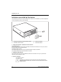
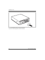
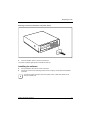
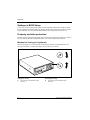
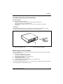
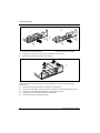
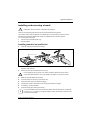
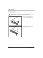
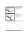
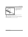
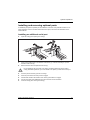
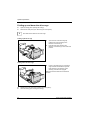
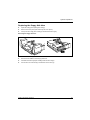
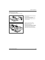
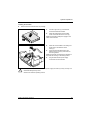
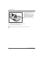
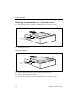
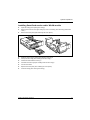
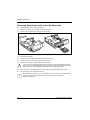
System expansions Installing the floppy disk drive 2 2 1 ► Push the drive into the casing in the direction of the arrow (1). ► Fold up the drive cage (see "Folding up the drive cage"). ► Fasten the floppy disk drive with the screws (2). ► Connect the cables. ► Fold down the drive cage (see "Folding down the drive cage"). ► Replace the cross piece (see "Installing the cross-piece"). ► Close the casing (see "Closing the casing"). i 62 It may be necessary to modify the entry for the drive in the BIOS Setup. Fujitsu Technology Solutions System expansions Replacing hard disk ► Open the casing (see "Opening the casing"). 1 3 2 ► Remove the cross-piece (see "Removing the cross-piece”). ► Remove the data and the power supply connectors from the mainboard. ► Disconnect the power supply connector from the hard disk. ► Open the lock of the drive cage by pressing the catch (a) lightly in the direction of the arrow (1). ► Fold the drive cage upward in the direction of the arrow (2) until it clicks into position. ► Fold the power supply upward in the direction of the arrow (3) until it engages. 1 Fujitsu Technology Solutions 63 System expansions Removing the hard disk ► Remove all connected cables (1) from the hard disk. ► Press the lever of the hard disk carrier in direction of the arrow (2). ► Remove the hard disk with the bracket out of the device in the direction of the arrow (2). ► Pull the support rail (1) of the bracket somewhat toward the outside. ► Remove the hard disk from the bracket in the direction of the arrow (2). 1 2 3 2 1 i 64 It may be necessary to modify the entry for the drive in the BIOS Setup. Fujitsu Technology Solutions System expansions Installing the hard disk ► Remove the new hard disk from the package. 2 ► Pull the support rail (1) of the bracket somewhat toward the outside. ► Place the hard disk into the hard disk carrier in the direction of the arrow (2). Make sure that the bracket pins engage in the holes of the hard disk. 1 ► Place the new hard disk in the casing at a slight angle in the direction of the arrow (1). ► Press the hard disk downward in the direction of the arrow (2) until it rests on the casing bottom. 3 2 1 Make sure that the rear edge of the hard disk is flush with the marking on the casing bottom. ► ! Plug the data and the power supply connectors into the hard disk. Even if your serial-ATA hard disk has two power supply connectors you may use only one. Otherwise damages may result. Observe the vendors operating manual. Fujitsu Technology Solutions 65 System expansions 1 3 ► Fold down the power supply in the direction of the arrow (1) until the power supply engages. ► Press on the locking lug (2) of the drive cage and then fold the drive cage with light pressure in the direction of the arrow (3) until the lever engages. Make sure that the cables are not kinked or pinched. 2 ► Connect the power supply connector. ► Replace the cross piece (see "Installing the cross-piece"). ► Close the casing (see "Closing the casing"). i 66 It may be necessary to modify the entry for the drive in the BIOS Setup. Fujitsu Technology Solutions System expansions Replacing second hard disk in 3 ½ inch drive cage ► Open the casing (see "Opening the casing"). ► Remove the cross-piece (see "Removing the cross-piece”). ► Fold up the drive cage (see "Folding up the drive cage"). Removing second hard disk 1 ► Remove the screw (1). ► Disconnect the cables from the hard disk. ► Remove the drive the direction of the arrow out of the casing. ► Slide the drive into the casing in the direction of the arrow. ► Secure the hard disk with the screws (1). ► Connect the cables. ► Fold down the drive cage (see "Folding down the drive cage"). 1 Installing second hard disk 1 1 ► If necessary, mount the plastic drive cover (see "Installing plastic drive cover"). ► Replace the cross piece (see "Installing the cross-piece"). ► Close the casing (see "Closing the casing"). i It may be necessary to modify the entry for the drive in the BIOS Setup. Fujitsu Technology Solutions 67 System expansions Replacing second hard disk in 5 ¼ inch drive carrier ► Remove the drive carrier as described in "Replacing drive in 5 ¼ inch bay" chapter. Removing the hard disk 2 1 1 1 1 ► Remove the screws (1). ► Pull the hard disk out of the drive carrier in the direction of the arrow (2). Installing the hard disk 1 2 2 2 2 ► Remove the new hard disk from the package. ► Slide the hard disk into the drive carrier in the direction of the arrow (1). ► Secure the hard disk with the screws (2). ► Remove the drive carrier as described in "Replacing drive in 5 ¼ inch bay" chapter. 68 Fujitsu Technology Solutions System expansions Installing/removing a SmartCard reader and/or WLAN module (optional) You can also install a SmartCard reader and/or a WLAN module for wireless LAN (Local Area Network) in place of the drive in the installation bay of the floppy disk drive. i The SmartCard reader and WLAN module can be installed together in the carrier. However, you can also install only one of the two boards. The WLAN module is installed in the lower slot of the carrier and the SmartCard reader in the upper slot of the carrier. If you want to install the SmartCard reader and the WLAN module together, first install the WLAN module. Removal is carried out in the reverse order. Screwing WLAN module onto carrier 2 2 1 a ► Push the WLAN module - with the component side facing downwards - in the direction of the arrow (1) into the guide (a). ► Fasten the WLAN module with the screws (2). ► Push the SmartCard reader - with the component side facing downwards - in the direction of the arrow (1) into the guide (a). ► Fasten the SmartCard reader with the screws (2). a Screwing SmartCard reader onto carrier 2 2 a a 1 Fujitsu Technology Solutions 69 System expansions Removing SmartCard reader from carrier 1 1 ► Loosen the screws (1). ► Pull the SmartCard reader out of the carrier in the direction of the arrow (2). ► Loosen the screws (1). ► Pull the WLAN module out of the holder in the direction of the arrow. Removing WLAN module from carrier 1 1 70 Fujitsu Technology Solutions System expansions Installing SmartCard reader and/or WLAN module ► Open the casing (see "Opening the casing"). ► Remove the cover from the upper casing top cover if necessary (see "Removing plastic drive cover"). ► Remove the cross-piece (see "Removing the cross-piece"). 1 1 ► Slide the carrier into the casing in the direction of the arrow. ► Fold up the drive cage (see "Folding up the drive cage"). ► Fasten the holder with the screws (1). ► Fold down the drive cage (see "Folding down the drive cage"). ► Connect the cables. ► Replace the cross piece (see "Installing the cross-piece"). ► Close the casing (see "Closing the casing"). Fujitsu Technology Solutions 71 System expansions Removing SmartCard reader and/or WLAN module ► Open the casing (see "Opening the casing"). ► Remove the cross-piece (see "Removing the cross-piece”). ► Fold up the drive cage (see "Folding up the drive cage"). 1 1 ► Remove the screws (1). ► Disconnect the cables. ► Fold down the drive cage (see "Folding down the drive cage"). ► Pull the holder out of the casing in direction of the arrow. ► Replace the cross piece (see "Installing the cross-piece"). ! If you remove the SmartCard reader and/or the WLAN module without replacing it with a floppy drive, you must reinstall the bay cover for reasons of cooling and fire protection and to comply with the prevailing EMC (electromagnetic compatibility) regulations. ► Mount the cover in the casing top cover if necessary (see "Installing plastic drive cover"). ► Close the casing (see "Closing the casing"). i 72 More detailed information on the use of Wireless LAN can be found in the "Wireless LAN" manual. This manual is provided as PDF file on the "User Documentation" or "Drivers & Utilities" CD. Fujitsu Technology Solutions System expansions Extensions to the mainboard The description of how to upgrade the main memory and/or processor is contained in the manual for the mainboard. ► Open the casing (see "Opening the casing"). ► Fold up the drive cage (see "Folding up the drive cage"). Upgrading main memory ► Upgrade the memory according to the description in the manual for the mainboard. ► Fold down the drive cage (see "Folding down the drive cage"). ► Close the casing (see "Closing the casing"). Replacing the processor Before you can replace the processor, you need to folding up the ventilation duct (if equipped). Folding up the ventilation duct Fujitsu Technology Solutions ► Grasp the ventilation duct from above and fold it up. ► Disconnect the power supply cable of the processor fan from the mainboard (refer to the manual for the mainboard). ► Replace the processor as described in the manual for the mainboard. 73 System expansions Folding down the ventilation duct 74 ► Connect the power supply cable to the processor fan (refer to the manual for the mainboard). ► Fold down the ventilation duct. ► Connect all cables which were previously disconnected or removed. ► Close the casing (see "Closing the casing"). Fujitsu Technology Solutions System expansions Replacing lithium battery In order to permanently save the system information, a lithium battery is installed to provide the CMOS-memory with a current. A corresponding error message notifies the user when the charge is too low or the battery is empty. The lithium battery must then be replaced. For 0-Watt devices: As an interim solution, the device can be started using the emergency on button at the rear, see chapter "Switching on a device when the lithium battery is discharged (0-Watt devices)”. ! Incorrect replacement of the lithium battery may lead to a risk of explosion! The lithium battery may be replaced only with an identical battery or with a type recommended by the manufacturer. Do not throw lithium batteries into the household waste. They must be disposed of in accordance with local regulations concerning special waste. Make sure that you insert the battery the right way round: The plus pole must be on the top! The lithium battery holder exists in different designs that function in the same way. 3 2 2 3 1 ► Press the catch in the direction of the arrow (1). The battery jumps out of the holder slightly. ► Remove the battery (2). ► Push the new lithium battery of the identical type into the holder and press it downward until it engages. Fujitsu Technology Solutions 75 System expansions 76 Fujitsu Technology Solutions Technical data Electrical data Regulations complied with: IEC60950/EN60950, UL60950, CSA22.2 No.60950 Protection class: I Rated voltage range: 100 V -240 V Frequency: 50 Hz - 60 Hz Maximum rated current (device-dependent) ● Device with monitor socket: 100 V - 127 V 200 V - 240 V 7.0 A 3.5 A ● Device without monitor socket: 100 V - 127 V 200 V - 240 V 4.0 A 2.0 A ● Optional monitor socket (output): 100 V - 127 V 200 V - 240 V 3.0 A 1.5 A Dimensions Width/depth/height: 350 mm/383 mm/95 mm Weight With the basic configuration approx. 9.7 kg Environmental conditions Environment class (3K2) Environment class (2K2) DIN IEC 721 part 3-3 DIN IEC 721 part 3-2 Temperature: ● Operating (3K2) ● Transport (2K2) 15 °C .... 35 °C -25 °C .... 60 °C Condensation in operating must be avoided. Clearance required to ensure adequate ventilation: ● ● Without air vents With air vents i min. 10 mm min. 200 mm The data sheet of the device contains further technical data. You will find the data sheet on the internet at http://ts.fujitsu.com/ Fujitsu Technology Solutions 77 Technical data 78 Fujitsu Technology Solutions Index 3 3 1/2-inch drive 61 5 5 1/4-inch drive 61 A Access permission, SmartCard 34 Additional serial port, installing 57, 58 Anti-theft protection 32 ATA drive, serial 61 Audio input 11 Audio output 11 B Battery 82 BIOS Setup 30 security functions 32 system settings 30 Board 43 installing 49, 52 installing in low-profile slot 49 removing 49, 54 removing from low-profile slot 50 with a locking device installing 49 removing 50 Board bracket installing 51 removing 51 Button ON/OFF switch 25 C Cable connecting 10 disconnecting 10 Carrier installing 46 removing 46 Casing closing 45 lead-sealing 32 locking 31 locking mechanically 30 opening 44 unlocking 31 Casing lock 30 CD-ROM Fujitsu Technology Solutions indicator 16 CE certificate 4 CE marking 4 Chain 32 Changing Lithium battery 82 Changing, lithium battery 82 Class B Compliance Statement 5 Clearance 85 Configuration, BIOS Setup 30 Connecting keyboard 13 mouse 13 PS/2 mouse 13 standard keyboard 13 USB keyboard 13 Contents of delivery 7 Ctrl+Alt+Del 27 Cursor keys 25 D Data dimensions 85 environmental 85 weight 85 Data protection 30 Date not correct 41 Device Anti-theft protection 32 cannot be switched on 38 cannot boot 38 checking rated voltage 15 cleaning 3 closing 45 connecting 10, 14, 15 connecting devices 10 Extensions 43 indicators 16 lead-sealing 32 locking 31 locking mechanically 30 opening 44 ports 11 setting up 8 switching off 23, 24 switching on 19, 23 transporting 3 unlocking 31 Device drivers parallel port 14 79 Index serial port 14 USB 14 Dimensions 85 Disposal 4 Drive 61 accessible 61 changing 64 installing 61 non-accessible drive 61 removing 61 Drive cage 66 fold down 66 fold up 66 DVD indicator 16 E Electromagnetic compatibility 4 Energy saving 4 Environmental conditions 85 Environmental data 85 Ergonomic, video workstation 8 Error date 41 Device 38 message 41 mouse 41 screen 39 time 41 ESD 43 Extensions Device 43 mainboard 80 External devices connecting 10, 14 ports 11 F FCC statement 5 Floppy disk inserting 28 removing 28 working with 28 write-protection 28 write-protection, disabling 29 Floppy disk drive changing 67 indicator 16 installing 68 removing 67 Function keys 25 G Graphics card installing 59 80 removing 60 H Hard disk changing 69, 73 installing 69, 71, 73, 75 removing 69, 70, 73, 75 Hard disk contents, restoring 42 Hard disk indicator 17 Headphones 11 I IDE drive 61 Important notes 3 Indicator CD-ROM 16 device 16 DVD 16 floppy disk 16 hard disk 16, 17 SmartCard reader 16 Installation Software 21 switching on for the first time 18 Installing additional serial port 57 software 18 Installing plastic drive cover 63 Interfaces 11 K Kensington Lock 32 Key Alt Gr 27 Control 27 Ctrl 27 Enter 26 enter key 26 Num 27 Return 26 Shift 27 Key combination 25, 27 Keyboard 25 connecting 13 port 11, 13 Keypad alphanumeric 25 Keys 25 Ctrl key 27 Ctrl+Alt+Del 27 Menu key 27 Shift key 27 Start key 27 Fujitsu Technology Solutions Index L LAN port 11 Lead-sealing 32 Line in 11 Line out 11 Lithium battery 80 replacing 82 Lock 30 Low voltage directive 4 Low-profile boards 56 mounting slot adapter 56 removing slot adapter 56 M Main memory 80 upgrading 80 Mainboard, extensions 80 Manuals, further 42 Memory insufficient 42 not enough 42 Microphone jack 11 Monitor connecting 12 remains blank 39 switching off 24 switching on 19, 23 transporting 3 Monitor port 11 Monitor screen no screen display 39 Mouse connecting 13 error 41 Mouse pointer 41 Mouse port 11 N New installation, software 37 New software, installing 37 Notational conventions 2 Note boards 43 Notes CE certificate 4 disposal 4 energy saving 4 important 3 recycling 4 safety 3 Numeric keypad 25 O ON/OFF switch 23, 25 Fujitsu Technology Solutions Operating position horizontal 8 vertical 8 Operation 23 Other manuals 42 P Packing material 7 unpacking 7 Parallel port 11, 14 connecting devices 14 settings 14 Plastic drive cover removing 62 Port SCSI 11 Power-on indicator 16, 21, 23 dark 38 fails to light 16, 38 flashes 16 lights green 16 lights orange 16 Preparing for first use, overview 7 Preparing for use 7 overview 7 Printer 11 Processor 80 replacing 80 Property protection 30 Protection property and data 30 PS/2 mouse connecting 13 port 11 R Ready 21 Ready-to-operate 23 Recycling 4 Replacement Lithium battery 82 Replacing rear panel 47 Retransportation 3 S Safety 3 SCSI port 11 Security functions BIOS Setup 32 SmartCard 34 SmartLock 34 serial ATA drive 61 Serial port 11, 14 connecting devices 14 81 Index installing 57 settings 14 Setup, see BIOS Setup Signs and symbols 2 Slot adapter 56 SmartCard reader 76 indicator 16 installing 76, 78 operating 34 removing 76, 79 Software Installation 21 installing 18 new installation 37 Standard keyboard, connecting 13 Summer time 41 Surface 85 System board see mainboard System expansion 43 System password 23 System settings, BIOS Setup 30 Troubleshooting 37 T Technical data 85 Time daylight savings 41 not correct 41 Tips 37, 42 Transport 3 Trouble Device 38 mouse 41 screen 39 W Warm boot 27 Weight 85 Wireless LAN module installing 76, 78 removing 79 WLAN module installing 76, 78 removing 79 Write protection, floppy disk 28, 29 82 U USB Universal Serial Bus 11 USB devices connecting 14 software 14 USB port 13, 14 connecting devices 14 connecting keyboard 13 connecting mouse 13 V Ventilation area 8 Ventilation duct folding down 81 folding up 80 Vertical operating position 9 Video workstation 8 Fujitsu Technology Solutions