1
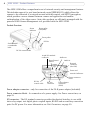
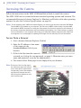
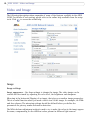
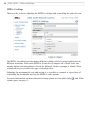
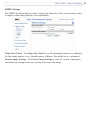
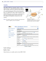
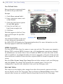
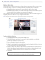
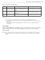
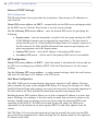
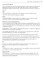
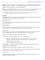
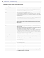
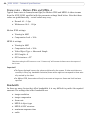
AXIS 223M - Unit Connectors
I/O Terminal connector pinout table
Pin
Function
Description
1
Output A
2
Output B
On the external device output terminals (A and B), there is no distinction
between positive and negative (+ and -). The terminals use a photocoupler and are electrically isolated from the other internal circuitry.
The maximum load should not exceed 100mA and the maximum voltage
should be not more than 50VDC or 35VAC.
3
Digital Input 1- Photocoupler Anode (+)
4
Digital Input 1 - Photocoupler Cathode (-)
Photocoupled Input 1. Electrically isolated from the chassis and connectors, this input can be supplied from an external DC voltage or the DC
Power Input/Output on pins 9 (DC+) and 10 (GND).
5
Digital Input 2 - Photocoupler Anode (+)
Photocoupled Input 2. As above.
6
Digital Input 2 - Photocoupler Cathode (-)
7
RS-485-A (non-inverting)
8
RS-485-B (inverting)
9
DC + Power Output
This can drive the photocoupler inputs or other equipment. The output
voltage level is 3.0 V. A maximum current of 100mA can be sourced from
the DC output.
10
GND
Ground.
A half-duplex RS-485 interface for controlling auxiliary equipment.
I/O Terminal connector schematic diagram
Example schematic diagram of the AXIS 223M terminal connector - showing possible
applications.
o1
o
2
Optional
Relay
Switch
o
o
Appliance
o o
o o
Mains Power
o3
o
o
24V DC
Switch, etc.
o4
o5
o6
A
RS-485
B
o7
o8
9
+
10
-
+
_
Active
Control
Device
External Device
o
51