1
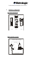
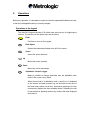
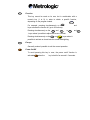
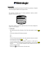
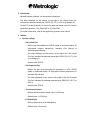
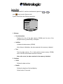
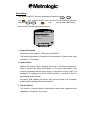
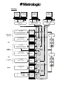
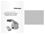
®
ScanPal 2
Portable Data Terminal
User manual
Printed August 2001
ScanPal 2
The content of this manual is the property of Metrologic Instruments Inc. The information contained in
this manual has been carefully checked and is considered to be accurate. Metrologic Instruments Inc.
accepts no responsibility regarding any inaccuracies in this document.
The information appearing in this document may be subject to modification, without prior notice, in
order to improve the reliability, design and function, and under no circumstances constitutes an
obligation on the part of the manufacturer.
All rights reserved. Under no circumstances may any part of this manual be reproduced or transmitted
in any form whatsoever, or by any means whatsoever, without the prior authorization of Metrologic
Instruments Inc.
Table of Contents
1. Introduction ........................................................................................................ 2
2. General characteristics...................................................................................... 3
2.1.
2.2.
2.3.
2.4.
2.5.
2.6.
2.7.
2.8.
2.9.
2.10.
2.11.
2.12.
Electrical characteristics ...................................................................................... 3
Environment ........................................................................................................ 3
Physical characteristics ....................................................................................... 3
CPU .................................................................................................................... 3
Memory ............................................................................................................... 5
Scanner............................................................................................................... 5
Screen................................................................................................................. 5
Keypad ................................................................................................................ 5
Indicator .............................................................................................................. 6
Communication ................................................................................................... 6
Programming language ....................................................................................... 6
Accessories......................................................................................................... 6
3. Hardware configuration ..................................................................................... 7
3.1.
3.2.
Front, back and side view.................................................................................... 7
RS232 and IrDA connection ................................................................................ 7
4. Software organization........................................................................................ 9
4.1.
4.2.
4.3.
4.4.
Kernel Module ..................................................................................................... 9
System Module.................................................................................................... 9
Program Module................................................................................................ 11
Creating your own program ............................................................................... 11
5. Operations ........................................................................................................ 13
5.1.
5.2.
5.3.
5.4.
5.5.
Operations at the keypad .................................................................................. 13
Program Mode................................................................................................... 15
System Mode .................................................................................................... 20
Kernel Mode...................................................................................................... 25
Overview ........................................................................................................... 27
6. Troubleshooting guide .................................................................................... 28
7. Metrologic reference and descriptions .......................................................... 31
1.
Introduction
The ScanPall2 is a high performance, light-weight and compact portable terminal,
designed for daily intensive use.
It is powered by two ‘AAA’ replaceable batteries or one Ni-MH rechargeable
battery and is equipped with a comprehensive set of development tools, including
a Windows based application generator, a "BASIC" compiler and a "C" compiler.
It is provided with an FSTN technology LCD graphics screen, with a resolution of
128x64 pixels, equipped with backlighting and a contrast control enabling it to be
read perfectly, whatever the ambient lighting.
Its CCD scanner and integrated RS-232 and IrDA communication ports make the
ScanPall2 ideal for inventory, stock control, document monitoring, factory floor
management, asset tracking, warehousing and distribution operations.
2.
General characteristics
The basic characteristics of the ScanPall2 are as follows:
Electrical characteristics
• Main battery................................ two AAA replaceable batteries or one Ni-MH
rechargeable battery
• Backup battery............................ 3.0 V, 7.0 mAh rechargeable lithium battery,
for the static random access memory
(SRAM) and the calendar
• Stand-alone operation ................ over 100 hours and over 50,000 reads (CPU
in low-speed mode and 1 read every 5
seconds)
Environment
• Humidity (operating) ................... non-condensing from 10% to 90%
• Humidity (storage) ...................... non-condensing from 5% to 95%
• Temperature (operating) ............. from -20° C to 60° C (-4° F to 140° F)
• Temperature (storage) ................ from -30° C to 70° C (-22° F to 158° F)
• EMC regulations ......................... FCC class A, CE and C-Tick approved
(EMC: Electromagnetic compatibility)
(FCC: Federal Communications Commission)
• Shock resistance ........................ 1.2 m (4’) drop on to concrete
Physical characteristics
• Dimensions................................. 145 mm (5.7”) L x 63 mm (2.5”) W x 33.5
mm (1.3”) H
• Weight ........................................ 180 g (6.3 oz) including batteries
• Color........................................... dark grey
• Material....................................... ABS (Acrylonitrile Butadiene Styrene)
CPU
• Toshiba 16-bit CMOS microprocessor
• Dual clock with low-speed mode capability for saving the batteries (for further
information on the Speed setting, refer to section 5.3)
Memory
• Program...................................... 1-MB Flash-ROM, flash memory used for
saving the program, character sets,
constants, etc.
• Data............................................ 1 MB SRAM, static random access memory
Scanner
The ScanPall2 is equipped with a CCD scanner. The scanners characteristics
are as follows:
ScanPal 2C (CCD)
• Minimum bar width...................... 0.102 mm (4 mil)
• Depth of field .............................. 30 mm – 160 mm (1.2” – 6.3 “) for 0.33 mm
(13 mil) codes
• Field width .................................. 124 mm (4.9”) @ 160 mm (6.3”)
• Scan rate .................................... 100 scans / second
• Ambient light rejection ................ 1200 Lux (direct lighting from the sun)
2500 Lux (fluorescent lighting)
Screen
• FSTN technology LCD graphics screen, with a resolution of 128x64 pixels and
LED backlighting.
Keypad
• 21 rubber keys, consisting of alphanumeric keys, arrow keys, function keys
and a key for triggering the scanner.
Indicator
• Buzzer ........................................ audible indicator, programmable from 1 KHz
to 4 KHz, low-power transducer type
• LED ............................................ dual-colour (green and red) programmable
LED
Communication
Three types of communication are possible: standard RS232, infrared and
screen/keyboard.
• RS232 ........................................ transmission speed up to 115,200 bps
• Infrared ....................................... standard 1.0 IrDA or high-speed IR:
- transmission speed up to 115,200 bps
- distance, 5 cm to 100 cm (2” to 39”)
- maximum angle, 30 °
• Keyboard .................................... only for data upload
Programming language
• Application generator (under Windows)
• "BASIC"
• "C"
Accessories
• Battery charger
• Ni-MH rechargeable battery
• Keyboard wedge cable
• Protective case
• High-speed IR transceiver
• Download/charger cradle
• RS232 cable
• Cradle power supply (only for the charger function)
For the references and descriptions, refer to section 7.
3.
Hardware configuration
Front, back and side view
63mm
IrDA
33.5mm
SCANPAL
711 2
LED
Indicator
Trigger
7 ABC
8 DEF
9G HI
4
5
6 PQR
1
2
3Y Z *
ESC
RS-232
side view
Battery
front view
back view
RS232 and IrDA connection
RS-232 & IrDA connection
IrDA connection
RS-232 port
IrDA Transceiver
IrDA port
30 o
5~100cm
SCANPAL
7112
7 ABC
8 DE F
4
5
1
2
RS-232 port
9 G HI
6PQR
3Y Z *
RS-232 port
ESC
AAA Battery*2
RS-232 connection
4.
Software organization
The ScanPall2 software system consists of three modules:
• The Kernel module
• The System (Operating System) module
• The Program module
Kernel Module
The Kernel module forms the heart of the system. It is extremely secure and
always protected by the system. Only a failure of the flash memory or incorrect
switching off of the power supply, during system restart after a kernel update, can
destroy the kernel. The Kernel module guarantees that the user can always
download his program, even when the operating system has been damaged by
the user program.
The Kernel module allows the following operations to be performed:
• Program Download
• Update Kernel
• Test & Calibrate
• Version
For further information, refer to section 5.4.
System Module
The System module is the operating system. It allows the following operations to
be performed:
• Memory
• Settings
• Reader
• Battery
• Test
• Download
• Version
For further information, refer to section 5.3.
Program Module
The Program module operates on top of the System module. The user programs
are downloaded into this module.
The user program, downloaded into the Program module, is started automatically
when the ScanPall2 is powered up.
The user program pre-loaded into the Program module of the ScanPall2 is the
application interpreter, making it possible to run an application created with the
application generator. By default, the application loaded is an inventory
application allowing the following operations to be performed:
• Collect data
• Upload data
• Utilities
For further information, refer to section 5.2.
Creating your own program
There are three development tools making it possible to create your own
application or program.
• The application generator
Requires prior loading, into the Program module, of the application
interpreter making it possible to run an application created with the
application generator.
For further details, see the application generator user manual.
• The "BASIC" compiler
Requires prior loading, into the Program module, of the "BASIC" interpreter
making it possible to run a "BASIC" program.
• The "C" compiler
For further information on the development tools, contact one of the Metrologic
offices:
Metrologic Instruments, Inc – Corporate Headquarters
Tel: 856-228-8100 Fax: 856-228-6673
Email: [email protected]
Metrologic Instruments GmbH – European, Middle East, & African
Headquarters
Tel: +49(0) 89 890 190 Fax: +49(0) 89 890 19 200
Email: [email protected]
Metrologic do Brasil Ltda. – Brazil only
Tel: 5511-5505-2396
Fax: 5511-5507-2301
Email: [email protected]
Metrologic South America – Outside Brazil
Tel: 5511-5505-6568
Fax: 5511-5505-1681
Email: [email protected]
Metro (Suzhou) Technologies Co., Ltd. – China
Tel: 86-512-2572511
Fax: 86-512-2571517
Email: [email protected]
Metrologic Asia (PTE) Ltd. – Singapore
Tel: 65-842-7155 Fax: 65-842-7166
Email: [email protected]
Metrologic Japan Co., Ltd. – Japan
Tel: 81-03-3839-8511
Fax: 81-03-3839-8519
Email: [email protected]
5.
Operations
Before any operation, it is advisable to make sure that the replaceable batteries are new,
or that the rechargeable battery is correctly charged.
Operations at the keypad
The ScanPall2 keypad consists of 20 rubber keys and one key for triggering the
scanner. The functions of the special keys are as follows:
Enter
Confirms an entry on the keypad.
Back Space
BS
Deletes the characters situated to the left of the cursor.
Space
SP
Inserts the space character.
X
Up
Moves the cursor upwards.
Y
Down
Moves the cursor downwards.
Alpha
Alphabetic / Numeric toggle
Makes it possible to change alternately from the alphabetic entry
mode to the numeric entry mode.
When the terminal is in alphabetic mode, a small icon is displayed
on the screen, and each numeric key can be used to insert one of
the three letters written on the key. Successive pressing of the key
successively displays the three available letters. Releasing the key
for one second or pressing another key confirms the letter displayed
and inserts it.
FN
Function
This key cannot be used on its own, but in combination with a
numeric key (1 to 9), in order to obtain a specific function,
depending on the program loaded.
1 STU
FN
For example, pressing simultaneously on the
keys activates the function #1 (up to 9 functions).
X
Pressing simultaneously on the FN and
, or
, keys makes it possible to adjust the screen contrast.
and
FN
and Y
Pressing simultaneously on the FN and
keys makes it
possible to activate or de-activate the screen backlighting.
ESC
Escape
Generally makes it possible to exit the current operation.
Power On/Off
To avoid pressing this key in error, the power on/off function is
activated only when the
key is held in for around 1.5 seconds.
Program Mode
This is the default operating mode when the ScanPall2 is powered up. It depends
on the user program loaded into the Program module.
The application interpreter and its inventory application, loaded by default,
displays the following main menu:
1.Collect data
2.Upload data
3.Utilities
JUN 16, 13:30
(R)
00000
The counter, located in the bottom right-hand corner of the screen, displays the
number of records collected.
1. Collect data
Data collection starts after confirmation of the Collect data operation, using the
, key.
A new screen displays the following two prompts:
Item:
Qty: 1
The Item (Article) prompt expects an item code, read by the scanner or entered
on the keypad and confirmed by the
key.
The Qty (Quantity) prompt offers, by default, a quantity of 1, which can be
modified by entering on the keypad the new quantity desired. This is confirmed
using the
key. The data collected are then recorded and the two
prompts are displayed again.
Pressing the
ESC
key allows a return to the main menu.
2. Upload data
Uploads the data collected, via the selected upload port.
The letter displayed on the screen, at the right of the Upload Data line,
indicates the selected upload port: RS232 (R) , IR (T), IrDA (I) or Wedge (K).
On the PC (under Windows), to receive the data and create a text file, use the
application generator, 232_Read.EXE or IR_Read.EXE.
For further information, refer to the application generator user manual.
3. Utilities
• System settings
- Set Upload Port
Defines the data upload port: RS232 (cable or download cradle), IR
(high-speed infrared transceiver), standard IrDA infrared or
screen/keyboard Wedge.
The letter displayed on the screen, at the right of the Set Upload
Port line, indicates the selected upload port: RS232 (R), IR (T), IrDA
(I) or Wedge (K).
Default value: RS232.
- Set Download Port
Defines the port for downloading an application or a file: RS232
(cable or download cradle), IR (high-speed infrared transceiver) or
standard IrDA infrared.
The letter displayed on the screen, at the right of the Set Download
Port line, indicates the selected download port: RS232 (R), IR (T) or
IrDA (I).
Default value: RS232.
- Transmission Speed
Defines the transmission speed, up to 115,200 bps.
Default value: 115,200 bps.
- LCD Backlight
Defines the duration of the backlighting.
Default value: 20 seconds.
- Data Deletion
Defines whether, after an upload, the data is deleted Manually, with
a request for confirmation, or Automatically, with no request for
confirmation.
Default value: Manually.
- Record Prompting
Activates (Yes) or de-activates (No) the display of the record
number, after confirmation of an entry.
Default value: Yes.
- View Settings
Displays the various settings.
• Browse Data
Displays the data collected. The
a loop, of all the data collected.
-
and
¯
keys allow scrolling, in
• Delete Data
Deletes the last record or all the records collected.
• Reading Test
Tests the read performance of the scanner and displays the bar code
read, its length and its type (symbology).
The symbologies enabled by default are as follows:
Code 39
Industrial 2/5
Interleaved 2/5
Codabar
Code 93
Code 128
UPCE without Addon
EAN8
EAN13/UPCA without Addon
The other symbologies can be enabled by the application generator.
• Set Date & Time
Defines the date and time.
• Download Program
Downloads an application (*.ATX) created with the application generator
into the ScanPall2 Portable Terminal, via the selected download port.
The letter displayed on the screen, at the right of the Download Program
line, indicates the selected download port: RS232 (R), IR (T) or IrDA (I).
On the PC (under Windows), use the application generator or
ATX_Load.EXE.
For further information, refer to the application generator user manual.
• Memory & Battery
Displays the size of the data memory (SRAM) in kilobytes, the voltage of
the replaceable batteries or the rechargeable battery, and the voltage of
the backup battery.
• Download Lookup
Downloads a Lookup File containing, for example, an item database, into
the ScanPall2, via the selected download port.
On the PC (under Windows), use the application generator or
DLookup.EXE.
Note: this function is not available if the application loaded does not use
a lookup file.
For further information, refer to the application generator user manual.
System Mode
Turn off the ScanPall2, and then simultaneously press the 7 ABC , 9 GHI
and
keys to enter System mode.
System mode offers the following operations:
System Menu
1 Memory
2 Setting
3 Reader
4 Battery
5 Test
6 Download
7 Version
1. Memory
• Size Information
Displays the size of the data memory (SRAM) and the size of the
program memory (Flash ROM), in kilobytes.
• Initialize
Initializes the data memory (SRAM).
Note: after an initialization, the data contained in the memory is deleted.
• Test
Tests the data memory. For a static random access memory (SRAM)
size of 256 KB, the test takes around 15 seconds.
Note: after a test, the data contained in the memory is deleted.
2. Settings
• Clock
Defines the date and time.
• Backlit
Defines the duration of the backlighting.
Default value: 20 seconds.
• Speed
Defines the CPU operating speed. Five speeds are available:
Speed
Consumption
Full ......................... 39 mA
1/2.......................... 22 mA
1/4.......................... 12 mA
1/8............................ 7 mA
1/16.......................... 5 mA
The consumptions are given for normal operation, with no scanner
reading or data transmission.
If the full-speed mode is not necessary, choose the lowest speed, in
order to save the batteries.
Default value: Full speed.
• Auto Off
Defines the time beyond which power down is automatic, when no
operation has been performed during this time period. If this value is
equal to zero, the function is de-activated.
Default value: 10 minutes.
• Power On
Two possible selections:
Program Resume, which starts the program from the last session used
before power down; or Program Restart, which restarts the program from
the beginning.
Default value: Program Resume.
• Key Click
Enables or Disables the issuing of a sound when a key is pressed.
Default value: Enable.
3. Reader
Tests the scanner read performance and displays the bar code read, its
length, and a letter identifying the code type (symbology).
The symbologies enabled by default are as follows:
Symbology
Identifier
Code 39 ..................................... A
Industrial 2/5 .............................D
Interleaved 2/5 ........................... E
Codabar .....................................G
Code 93 .....................................H
Code 128 ....................................I
UPCE without Addon.................. J
EAN8 .........................................M
EAN13/UPCA without Addon ..... P
The other symbologies must be enabled by programming.
4. Battery
• Main
Displays the voltage of the replaceable batteries or the rechargeable
battery.
An icon, representing the battery, is permanently displayed on the
screen, thus making it possible to view the charge state. When the
battery icon is completely empty, the batteries should be replaced or the
rechargeable battery recharged.
• Backup
Displays the voltage of the backup battery.
5. Test
• Buzzer
Tests the buzzer by means of the emission of different frequencies and
durations.
Press the
• LCD & LED
key to start or stop the test.
Tests the LCD screen and the dual-colour LED.
Press the
key to start or stop the test.
• KBD
Tests the keypad keys.
Pressing a key displays its value on the screen. The FN
must be used in combination with a numeric key (1 to 9).
Press the
ESC
function key
key to stop the test.
6. Download
• RS232
Downloads a user program (*.SHX) into the ScanPall2, via the RS232
port (cable or download cradle).
On the PC (under Windows), use DownLoad.EXE. The speed can go up
to 115,200 bps.
• IR (High-speed infrared)
Downloads a user program (*.SHX) into the ScanPall2, via the highspeed infrared transceiver.
On the PC (under Windows), use IRLoad.EXE. The speed can go up to
115,200 bps.
• IrDA
Downloads a user program (*.SHX) into the ScanPall2, via the standard
IrDA infrared.
On the PC (under Windows), use DownLoad.EXE. The speed can go up
to 115,200 bps.
7. Version
Displays the following information:
Hardware version number .........................(H/W)
Serial number............................................ (S/N)
Manufacturing date ...................................(M/D)
Kernel version number ..............................(KNL)
Library version number.............................. (LIB)
User program ........................................... (USR)
Kernel Mode
Turn off the ScanPall2, and then simultaneously press the 7 ABC
, 9 GHI
and
keys to enter System mode; next turn off the ScanPall2, and then
STU
1
7 ABC
simultaneously press
the
,
and
keys to enter Kernel mode.
Kernel mode offers the following operations:
Kernel Menu
1 Program Download
2 Update Kernel
3 Test & Calibrate
4 Version
1. Program Download
Downloads a user program (*.SHX) into the ScanPall2.
The download procedure is identical to that described in System mode (refer
to section 5.3, Download).
2. Update Kernel
Updates the system kernel. Updating the kernel is sometimes necessary in
order to improve the system performance, or for some other reason. This
function guarantees that the latest version of the kernel is being used. The
procedure for updating the kernel (KSP2-xxx.SHX) is identical to that for
downloading a user program.
Be careful: after updating the kernel, wait until the system has completely
restarted before powering down the ScanPall2.
3. Test & Calibrate
This function is intended solely for performing various tests, diagnostics and
calibrations in the factory. Do not use.
4. Version
Displays the following information:
Hardware version number .........................(H/W)
Serial number............................................ (S/N)
Manufacturing date ...................................(M/D)
Kernel version number ..............................(KNL)
Overview
R232_Read.EXE
To be defined
by
programming
DLookup.EXE
or
or directly
from AG_SP2.exe
Ir_Read.EXE
or directly
from AG_SP2.exe
To be defined
by
programming
Data
Data
Data
Application
"BASIC" program
"C" program
File Ý.ATX
Application created with the application
generator AG_SP2.EXE
ATX_Load.EXE
Program
Module
or directly
from AG_SP2.EXE
ScanPal 2
off
Application
generator
File USP2Ý.SHX
Application interpreter (1)
DownLoad.EXE
or
IrLoad.EXE
System
menu
Download
option
7 ABC
+
OR
9 GHI
File Ý.SYN
"BASIC" program created with
the "BASIC" compiler BC.EXE
SynLoad.EXE
or directly
from BC.EXE
+
System
menu
ownload
Basic
option
"BASIC"
compiler (3)
System
Module
File BCÝ.SHX
"BASIC" interpreter (2)
DownLoad.EXE
or
IrLoad.EXE
System
menu
Download
option
ScanPal 2
off
OR
"C" compiler
(3)
File Ý.SHX
Compiled "C" program
DownLoad.EXE
or
IrLoad.EXE
1 STU
System
menu
Download
option
+
7 ABC
+
Update
File KSP2Ý.SHX
DownLoad.EXE
Kernel
or
IrLoad.EXE
Kernel
menu
pdate
Kernel
option
Kernel
Module
File
or
or
USP2Ý.SHX
BCÝ.SHX
Ý.SHX
DownLoad.EXE
or
IrLoad.EXE
Kernel
menu
rogram
Download
option
6.
Troubleshooting guide
• The ScanPall2 doesn’t come on after the
key has been pressed.
Change the batteries or recharge the battery.
• The ScanPall2 doesn’t come on after the batteries have been changed or
the battery recharged.
Check that the replaceable batteries are correctly installed in their
compartment and that the compartment (or the rechargeable battery) is
properly engaged in the terminal.
If the problem persists, contact Technical Support.
• The battery icon, indicating the charge state, is empty.
Change the replaceable batteries or recharge the battery.
• No transmission between the ScanPall2 and the host system (PC or
other), via the RS232 port (cable or download cradle).
Check that the RS232 cable is correctly connected to the host system and
to the ScanPall2 or to the download cradle.
For transmission using the download cradle, check that the ScanPall2 is
correctly inserted in its cradle.
Check that the communication settings of the host system match those of
the ScanPall2.
• No transmission between the ScanPall2 and the host system (PC or
other), via the high-speed IR transceiver.
Check that the IR transceiver is correctly connected.
Check that the communication settings of the host system match those of
the ScanPall2.
Check that the ScanPall2 is correctly positioned in the IR transceiver read
area (a distance of 5 cm to 100 cm, 2” to 39”, and a maximum angle of 30°).
• The keypad doesn’t work correctly.
Turn off the ScanPall2, and then simultaneously press the
7 ABC
,
9 GHI
and
keys to enter System mode. Select the Test KBD option and carry
out the keypad key test.
If the problem persists, contact Technical Support.
The scanner doesn’t work.
Check that the symbologies of the codes read are enabled.
Check whether the battery icon, indicating the charge state, is empty. If this
is the case, change the replaceable batteries or recharge the battery.
If the problem persists, contact Technical Support.
7.
Metrologic references and descriptions
Part Number
Description
Basic ScanPal 2 CCD kit, including:
SCANPAL2CB
- 1 ScanPal 2 CCD portable terminal
- 2 AAA batteries
- 1 RS232 cable
- CD includes:
Application Generator
User Manual
Advanced ScanPal 2 CCD kit, including:
SCANPAL2CE-US
- 1 ScanPal 2 CCD portable terminal
- CD includes:
- 1 download/charger cradle and US power supply
Application Generator
- 1 RS232 cable
User Manual
- 1 rechargeable battery
Advanced ScanPal 2 CCD kit, including:
SCANPAL2CE-EC
- 1 ScanPal 2 CCD portable terminal
- CD includes:
- 1 download/charger cradle and Euro power supply Application Generator
- 1 RS232 cable
User Manual
- 1 rechargeable battery
46-46539
Dual Battery Charger, 1 NiMH battery and Euro Power Supply
46-46540
Ni-MH rechargeable battery pack
46-46541
Keyboard Wedge cable
46-46542
Protective Cover (imitation leather)
46-46543
IR Transceiver with Euro Power Supply
46-46544
"BASIC" compiler and license
46-46545
"C" compiler and license
46-46546
Download Cradle/Battery Charger, 1 NiMH battery and Euro Power Supply
46-46547
Dual Battery Charger, 1 NiMH battery and US Power Supply
46-46548
IR Transceiver with US Power Supply
46-46549
Download Cradle/Battery Charger, 1 NiMH battery and US Power Supply
46-46550
RS232 Cable