1
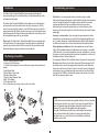
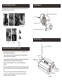
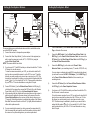
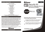
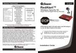
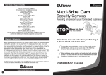
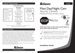
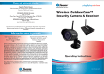
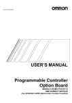
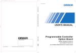
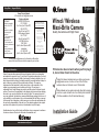
English
Help Desk / Support Details
Swann Technical Support
All Countries E-mail: [email protected]
Telephone Helpdesk
FCC WARNING
UNITED STATES toll free
STATEMENT
This device complies
877-274-3695
with Part 15 of FCC
(Sun-Thurs, 2pm-10.30pm PST)
Rules.
800-627-2799
Operation is subject to
(Mon-Fri,
9am-1pm PST)
the following two
USA Exchange & Repairs
conditions:
562-777-2551
(1) This device may not
cause harmful
(Mon-Fri, 9am-5pm PST)
interference, and
AUSTRALIA toll free
(2) This device must
1300 13 8324
accept any interference
(Mon-Fri,
9am-5.30pm Aus EST)
received,
International
Including interference
that may cause
+61 3 8412 4610
undesired operation.
(Mon-Fri, 9am-5.30pm Aus EST)
WARNING: IMPORTANT
NOTICE ABOUT CORRECT
USE OF POWER ADAPTER
The correct orientation
for the enclosed power
adapter is in a vertical
or floor mount position.
Wired / Wireless
Maxi-Brite Camera
Quality Surveillance with Night Vision
L’orientation correcte pour
L’adapteur secteur fourni
est dans une position
verticale ou planchermonte.
La orientacion correcta para
el adaptador electrico incluido
es en posicion vertical o instalado
en el suelo.
See http://www.worldtimeserver.com for information on different time
zones and the time in Melbourne Australia compared to your local time.
DC
12V
R
WE
PO
Warranty Information
Swann Communications warrants this product against defects in workmanship
and material for a period of one (1) year from it’s original purchase date. You must
present your receipt as proof of date of purchase for warranty validation. Any unit
which proves defective during the stated period will be repaired without charge for
parts or labour or replaced at the sole discretion of Swann. The repair or
replacement will be warranted for either ninety days or the remainder of the
original one year warranty period, whichever is longer. The end user is
responsible for all freight charges incurred to send the product to Swann’s repair
centres. The end user is responsible for all shipping costs incurred when shipping
from and to any country other than the country of origin. The warranty does not
cover any incidental, accidental or consequential damages arising from the use of
or the inability to use this product. Any costs associated with the fitting or removal
of this product by a tradesman or other person or any other costs associated with
its use are the responsibility of the end user. This warranty applies to the original
purchaser of the product only and is not transferrable to any third party.
Unauthorised end user or third party modifications to any component or evidence
of misuse or abuse of the device will render all warranties void.
If this device does not work when you first plug it
in, do not take it back to the store.
Contact the Swann Helpdesk using our fast e-mail service
[email protected] or call us on one of the Toll-Free
numbers shown on the back cover of this booklet.
Most problems can be quickly and easily fixed with a simple
e-mail or a quick chat with one of our friendly technical staff.
(Toll-Free available in the US and Australia only)
Installation Guide
SR231-WMX-1R006-060409
www.swannsecurity.com
Index
Introduction
Troubleshooting your camera
The Swann Wired / Wireless Maxi-Brite Camera incorporates the latest in
advanced technology. We feel confident that you will be pleased with the quality
and features of this product.
The Swann Wired / Wireless Maxi-Brite Camera allows you to transmit pictures
and sound with ease. As the radio waves it uses have a frequency of 2.4GHz,
they can be received within a radius of up to 165ft/50m in open line of sight. The
receiver works with other Swann cameras to allow you to have the option of using
different frequencies for different locations and conditions to ensure that you have
the best possible image quality for your situation.
Please note: The Swann Wired / Wireless Maxi-Brite Camera broadcasts video
in the public domain. The video signal is not encrypted and could potentially be
viewed by anyone with a similar 2.4GHz receiver unit. Please keep this in mind
when positioning and using any wireless camera equipment.
This Package Comes With ...
1. Wired / Wireless Maxi-Brite Camera
2. 4 channel 2.4GHz Receiver
3. 2 x Mains Power Adaptor for Camera & Receiver (design varies depending on
country)
4. Video Signal Cable
5. Wired Power & Video Cable
6. Wireless Power Cable
7. Power & Video Extension Cable
8. BNC - RCA Adaptor
9. This Instruction Sheet
If any of these items are missing, please contact your retailer.
Poor Picture: If you are using the camera as a wireless camera, realign
antennas until image quality improves, slightly adjust the position of the camera or
receiver. Change the location of the camera, or use a camera in the location
experiencing interference that is on a different channel. In some cases
interference may be caused by another device on a similar frequency to the
channel you are using. Change to one of the other channels and check the signal
quality again.
Lines only - no clear picture: if you are using the camera wirelessly, check to
confirm there is no microwave oven or other 2.4GHz equipment operating close
by ie; Cordless Telephones, Wireless Baby Monitors, Wireless LAN equipment
etc. Make sure the receiver is on the correct channel for the particular camera.
Picture ghosting or interference: Some home appliances such as Wireless
LANs, 2.4GHz portable telephones and Microwave ovens operate on or near the
2.4GHz frequency. If you receive interference from such an appliance, try moving
the camera or receiver to location further away from the appliance or in the event
of interference from a Wireless LAN device,
try changing the Wireless LAN to a different channel to improve the signal quality.
No picture: check the receiver to confirm it is turned ON and make sure the A/V
connection of the receiver is not plugged into the Audio-Out socket. Make sure
the receiver is on the correct channel. Check to ensure the camera is plugged in
and has power (cup your hands around the camera and you should see a faint
red glow from the IR LEDs). Check that the channel on the receiver is set to the
same as the camera you wish to view.
2
1
4
DC
PO
12V
3
NOTE:
R
WE
6
8
5
7
All jurisdictions have specific laws and regulations relating to the use of cameras.
Before using any camera for any purpose, it is the buyer’s responsibility to be
aware of all applicable laws and regulations that prohibit or limit the use of
cameras and to comply with the applicable laws and regulations.
The legality of watching people other than yourself changes from country to
country and even state to state. Contact your local government's privacy
information body or your local Police for more information on what if any
restrictions you may face.
Camera Features
Tips for locating your camera
You should position your cameras to cover the areas most exposed to risk. See
our suggestions below for some ideas:
Omni-Directional Antenna
Camera Hood
Infrared LEDs
1. Doorways
2. Windows
3. Car Parks
4. Verandahs
Detachable Camera Stand
Receiver Features
5. Reception
areas
6. Cash
register
7. Mix
dummies
& real
cameras
External Antenna
Important Information About This Product
Best Results are achieved where there is a clear “line of sight” between the
Camera/Transmitter and Receiver.
•
Interference from certain electronic equipment or the moving human body
can also affect the range obtainable.
•
Please test all devices before final installation, because transmission quality
can often be improved by moving the components slightly.
•
To avoid the risk of damage to the unit, use only the supplied power
adaptors.
•
Beware of humid locations. Water droplets or spray may damage the receiver
unit. If condensation does occur, do not use the equipment until it has dried
out.
•
Do not cut the DC power cable of the camera to fit with another power
source. This may result in damage to the camera & any unauthorised
modifications will void your warranty.
Channel LEDs
Channel selector
Button
CH1 CH2 CH3 CH4
•
DC
1 2V
A/V Output
(Audio not available
for this model)
R
WE
PO
DC Power Socket
Power Switch
Setting Up Your System - Wired
Setting Up Your System - Wireless
Power
Adaptor
for Camera
DVR or MONITOR
With RCA Sockets
1
VIDEO AUDIO
OUT
5
IN
Camera
4
2
3
Receiver
CH4
6
Wireless
Power Cable
1
Video
VIDEO AUDIO
Video
Signal Cable
Power
Switch
3)
3)
4)
Connect DIN Socket (2) on the Wireless Power Cable to the DIN plug (3)
on the back of the camera, then connect the DC Socket (4) on the Wireless
Power Cable to the DC Plug (5) on the Power Adaptor for Camera.
After connecting both the camera and the receiver make sure the receiver is
switched on and switched to the same channel as the camera. Press the
Channel Selector Button on the receiver until the video is shown on your
TV correctly. Obtain the best picture by adjusting the position of the Wireless
Maxi-Brite Camera and Receiver unit to suit. Try slightly different locations of
either unit for optimum results.
If you are mounting the camera to a ceiling, unscrew the camera stand (6)
from the camera body and carefully screw it into position on the top side of
the camera or the picture will appear on your screen upside down.
IN
4
5
2
3
Power
Extens & Video
ion Ca
ble
VIDEO AUDIO
7
9
1)
Connect DIN Socket (1) on the Wired Power & Video Cable to the DIN
Plug on the back of the camera,
2)
Connect the BNC Socket (2) on the Wired Power & Video Cable to the
BNC Plug (3) on the Power & Video Extension Cable, then connect the
DC Socket (4) on the Wired Power & Video Cable to the DC Plug (5) on
the Power & Video Extension Cable.
4)
Connect the BNC Plug (6) on the other end of Power & Video
Extension Cable to your monitoring device (TV, monitor, VCR,DVR...etc.)
Connect the Video Output Socket (1) on the receiver to the equipment you
wish to view the camera on (monitor, AV TV, VCR, DVR etc) using the
supplied Video Signal Cable.
NOTE: This camera doesn’t have Audio.
If you have an A/V TV with RCA sockets you will need to switch the TV to the
AV channel to view the camera.
To view the camera connected to your VCR, you will need to select the AV
input you have connected the camera to on the VCR, turn your TV onto the
channel you would normally use to view a tape or movie on your VCR. This
channel may be activated by a button on your remote that is marked with this
symbol
, or L1 or L2 or possibly AV1 or AV2 . Please read the instructions
for your VCR or TV for more information on using their A/V inputs.
VIDEO AUDIO
OUT
8
2)
3)
W
i
Vi red
de P o
o w
C a er
bl &
e
6
Receiver
Power Adaptor
The camera features an omni-directional antenna which is most effective when
use in the UPRIGHT position.
1) Connect the receiver to its respective power adaptor.
DVR or MONITOR
With RCA Sockets
Camera
If you are using a monitoring device with RCA connection (picture shown),
you will need to connect the BNC - RCA Adaptor (7) to the BNC Plug (6)
on the Power & Video Extension Cable first, then connect to your
monitoring device.
5)
Connect the DC Socket (8) on the Power & Video Extension Cable to
the DC Plug (9) on the Power Adaptor for Camera.
6)
If you have an A/V TV with RCA sockets you will need to switch the TV to
the AV channel to view the camera.
To view the camera connected to your VCR, you will need to select the AV
input you have connected the camera to on the VCR, turn your TV onto
the channel you would normally use to view a tape or movie on your
VCR. This channel may be activated by a button on your remote that is
marked with this symbol
, or L1 or L2 or possibly AV1 or AV2. Please
read the instructions for your VCR or TV for more information on using
their A/V inputs.