1
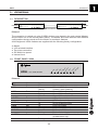
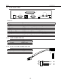
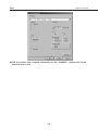
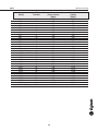
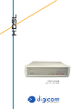
HDSL
User's Guide
rev. 1.0 05/2000
http://www.digicom.it
INDEX - DECLARATION CE OF CONFORMITY
HDSL
INDEX
INTRODUCTION
PREFACE
III
III
1. GENERAL
1.1. DESCRIPTION
1.2. FRONT PANEL VIEW
1.3. REAR PANEL VIEW
1.3.1. LINE CONNECTOR PIN
1.3.2. G.703 120 OHM CONNECTOR PIN
1.1
1.1
1.1
1.2
1.2
1.2
2. INSTALLATION
2.1. CONFIGURATIONS DESCRIPTION
2.1
2.1
DECLARATION CE OF CONFORMITY
Digicom S.p.A. via Alessandro Volta 39 21010 Cardano al Campo -Varesedeclares that this product satisfies the basic requirements of
Electromagnetic Compatibility and Safety of the below indicated Directive:
l 89/336/CEE of 3 may 1989 with subsequent modifications (Directive 92/31/CEE of april 28,
1992, Directive 93/68/CEE of July 22,1993 and Directive 93/97/CEE of 29 october 1993).
l 73/23/CEE of february 19, 1973 with subsequent modifications (Directive 93/68 ECC of july
22, 1993).
I
PREFACE
HDSL
INTRODUCTION
Digicom’s HDSL modems uses the HDSL technology (High-bit-rate Digital Subscriber Line)
that allows very high transfer speeds (2 Mbps) over leased lines. It is possible to connect
Digicom’s HDSL modems either over 2 wires and 4 wires lines. The main requirement for a
HDSL Lines is the wire metal continuity.
PREFACE
The following installation rules should be respected in order to have the best working order of the equipment and
for the user's safety.
Rapid changes of temperature or humidity should be avoided (0,03°C/min).
This equipment, including cables, should be installed in an area free from:
l Dust, humidity, heat from direct sun light.
l Objects which irradiate heat. These could cause damage to the container or other problems.
l Objects which produce a strong electtromagnetic field (loudspeakers, etc.)
l Liquids or chemical corrosive substances.
To avoid electric shock, the equipment should never be opened. Ask qualified personnel help.
Disconnect the power cable from the wall outlet when the equipment is not to be used for a long period. To
disconnect the cable pull it by the plug, never pull it by the cable itself.
If there should be liquid or object penetration in the equipment, disconnect the power cable and call a qualified
personl for testing.
CLEANING THE TERMINAL
Use a clean and soft cloth. Wet the cloth with water or natural detergent if it is necessary to remove any stains.
Never use chemical products such as petrol or solvents.
VIBRATIONS OR DROPPING
Caution against vibrations and dropping.
WARNING
This is a class A product.
In a domestic environment this product may cause radio interference in which case the user may be required to
take adequate measures.
III
GENERAL
HDSL
1. GENERAL
1.1. DESCRIPTION
HDSL line 2/4 wires
MASTER
V3
5/G
70
3
M
ST
/S
LV
LO
O
P
AL
M
LO
C
AL
M
R
EM
PW
R
LIN
K2
HDSL
HIGH SPEED MODEM
RX
LIN
K1
V3
5/G
70
3
M
ST
/S
LV
LO
O
P
AL
M
LO
C
AL
M
R
EM
HDSL
PW
R
TX
G.703/V35
LIN
K1
LIN
K2
TX
G.703/V35
HIGH SPEED MODEM
SLAVE
RX
Picture 1
The connection is carried out using 2 HDSL devices: one placed in the main centre (Master)
and the other one in the remote place (Slave). The Master and Slave devices have different
configurations but are equal as for the electric or mechanic features.
All the digicom’s HDSL modems are supplied with the following factory configuration:
l
l
l
l
l
Master
V.35 selected interface
Two wires connection
256 Kbit/s line speed
Internal clock
LI
N
K2
V3
5/
G
70
3
M
ST
/S
LV
LO
O
P
AL
M
LO
C
AL
M
R
EM
LI
N
K1
HDSL
PW
R
1.2. FRONT PANEL VIEW
HIGH SPEED MODEM
Picture 2
Name
PWR
LINK1
Color
Green
Red
LINK2
Red
V35/G703
Red
MST/SLV
Red
LOOP
Red
ALM LOC
Red
ALM REM
Red
Condition
Off
On
Flashing
On
Flashing
Off
On
Off
On
Off
On
Flashing
On
Flashing
On
Function
No power supply
Channel 1 Status: Connected with the remote one
Channel 1 Status: Searching
Channel 2 Status: Connected with the remote one
Channel 2 Status: Searching
Channel 2 Status: disabled
V.35 interface selection
G.703 interface selection
Device configured as Master
Device configured as Slave
Local Loop enabled
Loop enabled on the remote device
Problem with G.703 interface
Fault on the local device
Problem with the G.703 remote interface (managed
on Master device only)
Fault on the remote device
Flashing
1.1
GENERAL
HDSL
1.3. REAR PANEL VIEW
V.35
G703 75Ω
TX
PWR
CONFIG
LINE
RX
120 / 75Ω
G703 120 Ω
Picture 3
Name
PWR
CONFIG
LINE
G.703 120 ohm
120/75 ohm switch
G.703 75 ohm TX
G.703 75 ohm RX
G.703 75 ohm switch
V.35
Function
Power supply
9pin female connector for device configuration
HDSL line connector RJ11 4 contacts
G.703 interface 120 ohm 9 pin female connector
G.703 interface setup at 120 ohm or 75 ohm
G.703 interface 75 ohm coaxial BNC (send)
G.703 interface 75 ohm coaxial BNC (receive)
Join the shield of coaxial connectors G.703 75 ohm
V.35 interface, 25 pin female connector
1.3.1. LINE CONNECTOR PIN
PIN
3 and 4
1 and 2
Signal
HDSL Line 1
HDSL Line 2
1.3.2. G.703 120 OHM CONNECTOR PIN
PIN
1 and 2
4 and 5
Signal
Receive
Send
B
A
n.c.
n.c.
4321
B
1.2
A
1B
2B
1A
2A
5B
6B
5A
6A
RED
BROWN
PIN2
PIN1
WHITE
BLUE
PIN3
PIN4
INSTALLATION
HDSL
2. INSTALLATION
l
l
l
l
l
Remove the two HDSL modems from the package and check they are OK.
Using the “SetHDSL” program, configure one of the two modems as Slave.
Connect the HDSL lines between the modems (RJ11 connector).
Power on the modems that will connect using the factory configuration (default):
V.35 selected interface
two wires connection
256 Kbit/s line speed
At this point from the Master place and using the “SetHDSL” program, it is possible to
modify the system configuration to set the desired parameters.
2.1. CONFIGURATIONS DESCRIPTION
To configurate the Digicom’s HDSL modems it is necessary to use the Digicom “SetHDSL”
program.
The user can choose among seven base configurations (A-G) depending on the interface, the
wires of the line and the line speed.
Case Interface
A
G703
Flow
E1
Wires
4
B
G703
E1
2
C
G703
Nx64
2
D
G703
Nx64
4
E
V.35
Nx64
4
F
V.35
Nx64
2
G
V.35
Nx64
4
Interface/line speed
Interface speed fixed at 2 Mbit/s
Speed for each couple of wires 1 Mbit/s
Interface speed fixed at 2 Mbit/s
HDSL line speed 2 Mbit/s
Interface speed Nx64 Kbit/s (from 64 to 2 Mbit/s)
HDSL line speed depending on set time slot
Interface speed Nx64 Kbit/s (from 64 to 2 Mbit/s)
HDSL line speed depending on set time slot
Interface speed Nx64 Kbit/s (from 64 to 2 Mbit/s)
Speed for each couple of wires 1 Mbit/s
Interface speed Nx64 Kbit/s (from 64 to 2 Mbit/s)
HDSL line speed depending on set time slot
Interface speed Nx64 Kbit/s (from 64 to 2 Mbit/s)
HDSL line speed depending on set time slot
NOTE: “N” is the time slot number (i.e. if time slot is 4, Nx64=256 Kbit/s)
The base configuration (A-G) can be customized by setting the Framing type (G.703), the
interface (V.35), the speed (tile slot number), the clock, etc.
1.1
INSTALLATION
HDSL
NOTE: For further and complete information on the “SetHDSL”, please refer to the
program help on line.
1.2
INSTALLATION
HDSL
Interface speed
[Kbit/s]
64
128
192
256
320
384
448
512
576
640
704
768
832
896
960
1024 (1Mbps)
1088
1152
1216
1280
1344
1408
1472
1536
1600
1664
1728
1792
1856
1920
1984
2048 (2Mbps)
“N”
Time Slot
1
2
3
4
5
6
7
8
9
10
11
12
13
14
15
16
17
18
19
20
21
22
23
24
25
26
27
28
29
30
31
32
Line speed for each couple
of wire (4 wires)
[Kbit/s]
272
272
272
272
272
272
272
272
336
336
400
400
464
464
528
528
592
592
656
656
720
720
784
784
848
848
912
912
976
976
1040
1040
1.3
Line speed
(2 wires)
[Kbit/s]
272
272
272
272
336
400
464
528
592
656
720
784
848
912
976
1040
1104
1168
1232
1296
1360
1424
1488
1552
1616
1680
1744
1808
1872
1936
2000
2064
21010 Cardano al Campo VA
via A. Volta 39