1
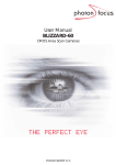
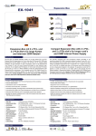
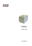
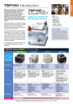
PCI31PUSB/LP & PEX312PUSB/LP
PCI/PCIe 12V Powered USB Card
PUSBADAP/LP
12V/24V Daughter Card
FCC Compliance Statement
This equipment has been tested and found to comply with the limits for a Class B digital
device, pursuant to part 15 of the FCC Rules. These limits are designed to provide reasonable
protection against harmful interference in a residential installation. This equipment generates,
uses and can radiate radio frequency energy and, if not installed and used in accordance with
the instructions, may cause harmful interference to radio communications. However, there is
no guarantee that interference will not occur in a particular installation. If this equipment does
cause harmful interference to radio or television reception, which can be determined by turning the equipment off and on, the user is encouraged to try to correct the interference by one
or more of the following measures:
• Reorient or relocate the receiving antenna.
• Increase the separation between the equipment and receiver.
• Connect the equipment into an outlet on a circuit different from that to which the receiver
is connected.
• Consult the dealer or an experienced radio/TV technician for help.
Use of Trademarks, Registered Trademarks, and other Protected Names and Symbols
This manual may make reference to trademarks, registered trademarks, and other protected
names and/or symbols of third-party companies not related in any way to StarTech.com.
Where they occur these references are for illustrative purposes only and do not represent an
endorsement of a product or service by StarTech.com, or an endorsement of the product(s)
to which this manual applies by the third-party company in question. Regardless of any direct
acknowledgement elsewhere in the body of this document, StarTech.com hereby acknowledges that all trademarks, registered trademarks, service marks, and other protected names
and/or symbols contained in this manual and related documents are the property of their
respective holders.
Instruction Manual
Table of Contents
Introduction ................................................................................... 1
Features.......................................................................................1
Package Contents........................................................................1
Hardware Guide.............................................................................. 2
PCI312PUSB/LP, PEX312PUSB/LP.............................................2
Jumper Settings............................................................................2
PUSBADAP/PUSBADAPLP.........................................................3
Hardware Installation..................................................................... 4
PCI312PUSB/LP, PEX312PUSB/LP & PUSBADAP/LP...............4
PCI312PUSB/LP or PEX312PUSB/LP Only................................5
PUSBADAP/PUSBADAPLP Only . ..............................................6
Software Installation...................................................................... 7
Specifications................................................................................. 8
Technical Support.......................................................................... 9
Warranty Information..................................................................... 9
i
Instruction Manual
Introduction
Thank you for purchasing a StarTech.com Powered USB 2.0 Adapter
Card (available in both PCI and PCI Express formats as well as Standard
and Low Profile). Now, adding Powered USB capability to a computer
has never been easier!
Fully compatible with USB1.1 OHCI and USB2.0 ECHI specifications, the
cards support data speeds of up to 480 Mbps and provide power to Powered USB devices through industrial standard Powered USB connectors.
Features
• Supplies power and data signals over hot-pluggable USB cable
• Mainboard can be linked to daughter board
• Daughter board and Main board can be used as stand alone devices
• Selectable power input
• Connectors offer cable locking mechanism
Package Contents
•
PCI312PUSB/LP: 1 x Powered USB Mainboard Card
or
PEX312PUSB/LP: 1 x Powered USB Mainboard Card
or
PUSBADAP/LP: 1 x Powered USB Daughter Board
• Instruction Manual
• Driver CD (PCI312PUSB/LP and PEX312PUSB/LP only)
• 9-Pin USB Header Cable (PUSBADAP/LP Only)
Please note that the Powered USB ports are color coded based on voltage capabilitythey support, as follows:
Yellow: 5V
Green: 12V
Red: 24V
1
Instruction Manual
Hardware Guide
PCI312PUSB/LP, PEX312PUSB/LP
J4:
USB Ports 4, 5
(for Expansion)
+5
DD+
G
+5
DD+
G
JP2:
+12V Selector
J5: AUX Power
J1~J3:
External
JP1:
Powered
USB Ports (x3)
+5V Selector
Jumper Settings
JP1 (+5V Selector)
Default: The USB2.0 Bus Power is supplied by the
motherboard PCI slot (DC+5V supplied from PCB)
The USB2.0 Bus Power is supplied by the AUX
power connector (J5).
This option provides more power for Powered USB
devices, but requires a connection to the computer
power supply.
2
Settings
Instruction Manual
Jumper Settings - Cont’d
JP2 (+12V Selector)
Settings
Default: The 12V power source of the Powered
USB connectors are supplied by the PCI slot into
which the card is installed
The 12V power source of the Powered USB connectors are supplied by the AUX power connector
(J5). This will require that a power cable be connected from the computer power supply to J5. This
option provides more power for the Powered USB
devices over the USB2.0 cable.
PUSBADAP/PUSBADAPLP
J1:
USB Input Connector
(from Host USB port)
JP1: +24V Power
Source Selector
J3: External
Input Power
DIN Connector*
+5
DD+
G
(from Regulator
or External Power
DIN connector)
+5
DD+
G
J5:
AUX Power Connector
J4:
*J3:
24V-keyed
Connector
Power DIN
Connector Pin
Assignment
J2:
12V-Keyed
Connector
3
Instruction Manual
Jumper Settings
JP2 (24V Selector)
Settings
Default: The power source of the 24V-keyed PoweredUSB connector is supplied from the internal
step-up switching regulator (jumpers must be set
identically, both at INT or EXT.
The power source of the 24V-keyed Powered USB
connector is supplied from the external Power DIN
input connector, in this case, a 24V AC adapter will
be required. Please see http://www.startech.com
for more information.
Hardware Installation
PCI312PUSB/LP, PEX312PUSB/LP & PUSBADAP/LP
This section details how to install PCI312PUSB/PEX312PUSB, in
conjunction with a daughter board, PUSBADAP:
1. Remove the computer cover. For more detailed instruction on how to
perform this step, please refer to the documentation that was included
with your computer at the time of purchase.
2. Locate an empty PCI/PCI Express slot and remove the metal bracket
covering the accompanying empty port/socket.
3. Connect one end of the 9-pin Header Cable (provided by
PUSBAD/LP) to the expansion port (depicted on pg. 2 as J4:USB
Ports 4, 5).
4. Position the card above the open PCI/PCI Express slot, ensuring that
the card is properly aligned with the slot. Insert the card firmly into the
slot, distributing force evenly across the length of the board, then fasten
the metal bracket to the computer case (using the screw removed in
step #2).
4
Instruction Manual
5. Remove a metal bracket that is adjacent to or near the one removed
in step #2, and fasten PUSBADAP/PUSBADAPLP directly to the metal
rear panel of the computer case.
6. Connect the remaining end of the 9-Pin USB Header Cable used in
step #3, to the USB IN connector, denoted as J1: USB Input
Connector (from Host USB port) (see diagram, pg.3) on the
PUSBADAP board.
7. PCI312PUSB/PEX312PUSB: By default, JP2 (see pg. 3) is set to PCI.
The card will draw power via the PCI/PCI Express slot into which it is
installed; as such, if you’ve left the JP2 jumper in the default
position, there will be no need to connect PCI312PUSB to the
computer power supply.
If JP2 has been switched to INT (Internal), you must connect PCI
312PUSB/PEX312PUSB to the computer power supply, by inserting an
available LP4 connector into the AUX Power Connector.
PUSBADAP: By default, JP2 is set to INT, commanding the card to
draw power from the computer power supply. As such, insert an LP4
power connector from the power supply, into the AUX Power
Connector.
If JP2 has been set to EXT, the PUSBADAP will draw power through
the External Input Power DIN Connector, and will require an external
power source (see http://www.startech.com for accessories).
8. Once both cards have been properly positioned, and the necessary
link has been made between them, close the computer case and
power on the computer.
PCI312PUSB/LP or PEX312PUSB/LP Only
This section details how to install PCI312PUSB/PEX312PUSB as a stand
alone card.
1. Remove the computer cover. For more detailed instruction on how to
perform this step, please refer to the documentation that was included
with your computer at the time of purchase.
5
Instruction Manual
2. Locate an empty PCI/PCI Express slot and remove the metal bracket
covering the accompanying empty port/socket.
3. Position the card above the open PCI/PCI Express slot, ensuring that
the card is properly aligned with the slot. Insert the card firmly into the
slot, distributing force evenly across the length of the board, then fasten
the metal bracket to the computer case (using the screw removed in
step #2, if necessary).
4. By default, JP2 (see pg. 3) is set to PCI, commanding the card to draw
power via the PCI slot into which it is installed. As such, if you’ve left
the JP2 jumper in the default position, there will be no need to connect
PCI312PUSB to the computer power supply.
If JP2 has been switched to INT (Internal), you must connect PCI
312PUSB to the computer power supply, by inserting an available LP4
connector into the AUX Power Connector.
5. Once the card is properly seated, and secured to the computer case,
close the computer case and power on thecomputer.
PUSBADAP/PUSBADAPLP Only
This section details how to install PUSBADAP as a stand alone card.
1. Remove the computer cover. For more detailed instruction on how to
perform this step, please refer to the documentation that was included
with your computer at the time of purchase.
2. Connect one end of the 9-Pin USB Header Cable (provided) to the
USB IN connector, denoted as J1: USB Input Connector (from Host
USB port) (see diagram, pg.3) on the PUSBADAP board.
3. By default, JP2 is set to INT, commanding the card to
draw power from the computer power supply. As such, insert an LP4
power connector from the power supply, into the AUX Power
Connector.
If JP2 has been set to EXT, the PUSBADAP will draw power through
the External Input Power DIN Connector.
4. Connect the remaining end of the 9-Pin USB Header Cable (see step
6
Instruction Manual
#2), to the USB Header connector on the host motherboard. For
further instructions on how to locate the appropriate connection on the
motherboard, please consult the documentation that was included with
your motherboard/computer at the time of purchase.
Software Installation
PCI312PUSB/LP and PEX312PUSB/LP are natively supported by Windows® XP (SP2) 2000 (SP4) and Vista™. As such, no driver installation
is required, as long as the necessary updates have been made to the
operating system(s).
For Windows 98SE or Windows ME installations, however, driver installation is required.
To install the drivers necessary for PCI312PUSB/LP or PEX312PUSB/LP
to function properly:
1. With the host computer powered on, insert the Driver CD that
accompanied your purchase of PCI312PUSB/PCI312PUSBLP into the
CD/DVD-ROM drive.
2. On the Driver CD, browse to the X:\USB 2.0\NEC folder, (where X de
notes the designated CD/DVD-ROM drive on the host computer) and
locate the folder that corresponds with the host computer operating
system.
3. Open the appropriate folder and locate the U2v2_1 application file.
Execute the file by double clicking on the icon/listing, to begin
installation.
4. Follow the installation through until you are asked if you would like to
reboot the computer. Select Yes, I want to restart my computer now
and click on Close.
Once the computer has rebooted, the operating system will detect the
presence of the card - installation is complete.
7
Instruction Manual
8
Instruction Manual
Specifications
PCI312PUSB
PEX312PUSB
3 x 12V Powered USB male
connectors
Connectors
1 x LP4 Connector
1 x Internal USB (9 pin) Header
Connector for expansion
1x Jumper Connector
OS Support
Dimensions
(L x W)
1x 12v Power USB Connector
1x 24v Power USB Connector
1x 4 pin Power Din Connector
1x Internal USB Connector
1x Jumper Connector
1x LP4 Connector
Windows® 2000/ME/2003/XP/Vista™
81.2 mm x 66.7 mm
(3.2 in ) x (2.63 in )
Regulatory
Certified
120 mm x 66.7 mm
(4.72 in ) x (2.63 in )
CE, RoHS, FCC
Maximum
Data
Transfer
Rate
Chipset
PUSBADAP
480Mbps
NEC
D720101GJ
NEC
D720101GJ +
TI XIO2000A
PCI Express
to PCI Bus
Translation
Bridge
9
N/A
Instruction Manual
Technical Support
StarTech.com’s lifetime technical support is an integral part of our commitment to provide industry-leading solutions. If you ever need help with your
product, visit www.startech.com/support and access our comprehensive
selection of online tools, documentation, and downloads.
Warranty Information
This product is backed by a lifetime warranty. In addition, StarTech.
com warrants its products against defects in materials and workmanship for the periods noted, following the initial date of purchase. During
this period, the products may be returned for repair, or replacement with
equivalent products at our discretion. The warranty covers parts and labor
costs only. StarTech.com does not warrant its products from defects or
damages arising from misuse, abuse, alteration, or normal wear and tear.
Limitation of Liability
In no event shall the liability of StarTech.com Ltd. and StarTech.com USA
LLP (or their officers, directors, employees or agents) for any damages
(whether direct or indirect, special, punitive, incidental, consequential, or
otherwise), loss of profits, loss of business, or any pecuniary loss, arising
out of or related to the use of the product exceed the actual price paid
for the product. Some states do not allow the exclusion or limitation of
incidental or consequential damages. If such laws apply, the limitations or
exclusions contained in this statement may not apply to you.
10
StarTech.com has been making “hard-to-find easy” since 1985,
providing high quality solutions to a diverse IT and A/V customer
base that spans many channels, including government, education
and industrial facilities to name just a few. We offer an unmatched
selection of computer parts, cables, A/V products, KVM and Server Management solutions, serving a worldwide market through our
locations in the United States, Canada, the United Kingdom and
Taiwan.
Visit www.startech.com today for complete information about all
our products and to access exclusive interactive tools such as the
Cable Finder, Parts Finder and the KVM Reference Guide. StarTech.com makes it easy to complete almost any IT or A/V solution.
Find out for yourself why our products lead the industry in performance, support, and value.