1
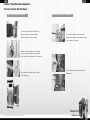
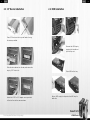
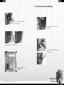
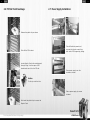
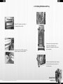
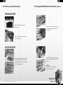
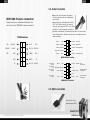
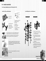
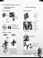
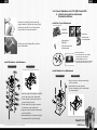
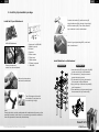
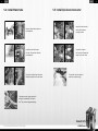
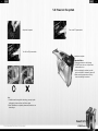
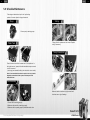
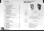
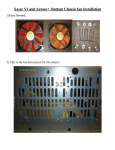
01
English
English
Chapter 1. Product Introduction
Contents
Specification
Chapter 1. Product Introduction
1.1
Specification
02
Chapter 2. Case Mechanical Operation
2.1
2.2
2.3
2.4
2.5
2.6
2.7
2.8
2.9
2.10
2.11
How to Open the Side Panel
-Open the left-hand side panel
-Open the right-hand side panel
5.25" Device Installation
-How to remove 5.25" device?
-How to put back the 5.25" drive bay cover?
3.5" Device Installation
HDD Installation
How to Remove the HDD Cage
PCI Slot Tool-Free Usage
Power Supply Installation
Sliding Motherboard Tray
How to open top sliding hood
-Top sliding hood
-Storage draw (optional)
Swappable HDD Module/ Fan Module (Optional)
VGA Fan Installation
03
03
04
05
06
06
07
08
10
11
12
14
15
15
15
16
17
Model
VG400LBWS
VG400LBNS
VG400LSWA
Case Type
Super Tower
Dime nsion (W*D*H)
250 x 660 x 605 mm
9.8 x 26.0 x 23.8 inch
VG400LSNA
Window si de panel
Yes
No
Yes
No
Sli ding mo therbo ard tray
Yes
Yes
Yes
Yes
Cable ma nag ement
Yes
Yes
Yes
Yes
Sli ding hood
Yes
Yes
Yes
Yes
Adjustable PSU bri dge
Yes
Yes
Yes
Material
Color
Yes
Front door: Aluminum / Chassis: 1.0mm SECC
All Aluminum
Chassis color: Black / Metal mesh : Red
Chassis color : Silver / Metal mesh : Black
- Front (intake) : 140 x 140 x 25mm blue LED fan, 1000rpm, 16dBA or 120 x 120 x25 mm fan (optional)
Chapter 3. Motherboard & Leads Installation
3.1
3.2
3.3
3.4
3.5
Motherboard Installation
Case LED connection
USB 2.0 & IEEE 1394 Firewire Connection
Audio Connection
eSATA connection
- Rear (exhaust) : 120 x 120 x25 mm blue LED fan, 1300rpm, 17dBA
Cooli ng System
18
19
20
22
22
Chapter 4. Other
4.1
Toughpower / Purepower / TR2
power supply series (optional)
23
- Top (exhaust) : 140 x 140 x 25mm TurboFan, 1000rpm, 16dBA or 120 x 120 x25 mm fan (optional)
- Bottom (intake) : Two 140 x 140 mm fans (optional) or two 120 x 120 x25 mm fan (optional)
- VGA (intake) : 140 x 140 x 25mm TurboFan, 1000rpm, 16dBA or 120 x 120 x25 mm fan (optional)
Mothe rboa rds
9.6" x 9.6" (Micro ATX), 12" x 9.6" (ATX), 12" x 13" (Extend ATX)
Drive Bays
7 (3 occupied by LCS module)
1 (Convertable from one 5.25" drive bay)
7
-5.25" Drive Bay
-3.5" Drive Bay
-3.5" Drive Bay (Hidd en)
Fron t I/O
e-SATA connector x 2, USB2.0 x 4, IEEE 1394 Firewire x 1, HD Audio
Exp ans ion Sl ots
10
Liquid Cooling System:
Chapter 5. Liquid Cooling Installation
5.1
5.2
5.3
5.4
5.5
5.6
5.7
5.8
5.9
5.10
Components check
Installation steps
Install waterblock
Install Water tube
Install Quickconn Connecter
Connect the Quickconn connector
Refill Coolant
Power on the system
Schedule Maintenance
Liquid Cooling Q&A
This time, don't let Xaser VI slip away !
- Three 5.25 Drive Bay design: liquid cooling system built inside
- Quick Disconnect Connector: Automatic non-spill valves, robust material one hand operation
25
26
27
37
38
39
39
42
43
45
- Performance Motorsports radiator:
(A) Dimension of radiator : H 153 x W 120 x T 28 mm
Liquid Cooling
System Applicati on
(B) Adjustable 120mm blue LED silent fan (1600~2400RPM)
- P500 liquid pump : Powerful DC 12V liquid pump (500L/hr)
- All copper water block: For Intel P4 775/478 and AMD AM2/K8
- Flow TX: Flow meter for liquid cooling system
- Reservoir: Contains 320 c.c. of liquid capacity
- Water tube: Transparent UV tube (3/8") ,
industrial-grade rubber tube (3/8", pre-assembled)
Xsase VI LCS
VG4000 Series
02
03
English
English
Chapter 2 Case Mechanical Operation
2.1 How to Open the Side Panel
Open the left-hand side panel
Open the right-hand side panel
To remove the left-hand side panel,
please remove upper and bottom
To remove the right-hand side panel,
screws on the back of the case.
please remove upper and bottom screws
on the back of the case.
Please find side panel key in the back
of the case, and open the side panel.
Make sure the side panel lock is opened.
Pull up the thumb screw to open the
Push down the thumb screw to open
side panel.
the side panel.
Xsase VI LCS
This time, don't let Xaser VI slip away !
VG4000 Series
04
05
English
English
2.2 5.25" Device Installation
How to remove 5.25" device?
1
2
Pull the right-hand side
of the lever to remove
the 5.25" device.
Remove the 5.25" drive bay
cover as shown.
How to put back the 5.25" drive bay cover?
Put 5.25" device into the
drive bay till the lockedposition.
Notice:
Install the 5.25" drive bay
It is possible to secure the 5.25"
cover as shown.
device by screws if not feel stable
enough.
Xsase VI LCS
This time, don't let Xaser VI slip away !
VG4000 Series
06
07
English
English
2.3 3.5" Device Installation
2.4 HDD Installation
Place 3.5" device on the tray and fasten it using
the screws provided.
Remove the HDD tray by
pressing the handle and
pull the tray out.
Slide the drive device into the bay and secure the
tray by 5.25" slot-in kit.
Place HDD on the tray.
Secure HDD using the clips onto the HDD tray for
Install the 5.25" to 3.5" adaptor cover provided
both side.
in the tool box to the case as shown.
Xsase VI LCS
This time, don't let Xaser VI slip away !
VG4000 Series
08
09
English
English
2.5 How to Remove the HDD Cage
Slide the HDD tray back to
the drive bay.
Unscrew the thumb screws of
the cage.
2
1
Press the handle to lock the HDD tray.
Push the handle down and pull
the cage out.
Organized HDD cable
management.
Xsase VI LCS
This time, don't let Xaser VI slip away !
VG4000 Series
10
11
English
English
2.6 PCI Slot Tool-Free Usage
2.7 Power Supply Installation
Release the plastic clip as shown.
Take off both side panels and
unscrew the thumb screws from
Take off the PCI bracket.
both side of PSU supporting bridge.
Locate Graphic Card to the motherboard
through fixing it on the space of PCI
bracket and insert it to the PCI slot.
Place power supply over the
location as shown.
Notice:
Fix the pin into the hole.
Fasten power supply by screws
included.
Push back the plastic clip to secure the
Graphic Card.
Xsase VI LCS
This time, don't let Xaser VI slip away !
VG4000 Series
12
13
English
English
2.8 Sliding Motherboard Tray
Adjust PSU supporting bridge to
the appropriate position.
Remove both side panels before
removing motherboard tray.
Remove the screws from the back
Fasten both side of PSU supporting
of the chassis.
bridge using the thumb screws.
Slide the motherboard tray towards
the back of the case to remove it
from the case.
Xsase VI LCS
This time, don't let Xaser VI slip away !
VG4000 Series
14
15
English
English
2.9 How to open top sliding hood
2.10 Swappable HDD Module/ Fan Module (Optional)
Top sliding hood
Remove screws from the top
sliding hood.
Lay down your case and unscrew
the thumbscrews to remove the
HDD cage
The top sliding hood allows easy
LCS maintenance.
Storage draw (optional)
Please find the storage draw from
the provided tool box. Then, put
the storage draw into the drive bay
till the locked-position.
Put a fan and secure it by screws
and thumb nuts provided in the
tool box.
Notice:
The direction of fan airflow
should be as shown.
Xsase VI LCS
This time, don't let Xaser VI slip away !
VG4000 Series
16
17
English
English
Chapter3 Motherboard & Leads Installation
2.11 VGA Fan Installation
3.1 Motherboard Installation
Each motherboard has different standoff layout. It is highly
suggested that you refer to your motherboard's manual when
installing motherboard into the Case. Xaser VI is applicable
with Extend ATX, ATX & Micro ATX motherboards. Your motherboard
may require a special I/O Panel, which should be included with
your motherboard.
Install 140mm fan with fan holder
provided in the tool box.
Placement Direction:
When installing the motherboard, make sure you follow the
direction provided by your motherboard manufacturer. On
most standard motherboards, the edge with external ports
goes to the rear part of the chassis. It is highly recommended
that you install CPU, heat sink and modular components
before fixing the motherboard inside the chassis.
= the locations of
the screw holes. Note
these locations and
place included
standoffs on the chassis
first.
Secure the fan holder to the
motherboard tray by screws.
Notice:
This side towards
the rear of the
chassis
The direction of fan airflow
should be as shown.
Above illustration is a sample of what
the motherboard's layout. For more
detail screw hole placement, please
refer to your motherboard manual.
Xsase VI LCS
This time, don't let Xaser VI slip away !
VG4000 Series
18
19
English
English
3.2 Case LED connection
3.3 USB 2.0 & IEEE 1394 Firewire Connection
USB connection
On the front of the case, you can find some LEDs and switch leads
Please consult your motherboard manual to find
(POWER SW*1, POWER LED*1, H.D.D. LED*1, RESET SW*1)
out the section of "USB connection".
Please consult user manual of your motherboard manufacturer, then
connect these leads to the panel header on the motherboard. These
USB Function
leads are usually labeled; if not, please trace them back to the case
front to find out their source.
- POWER LED
connects to your M/B at the PLED
RED
VCC / USB Power (+5C) for Port 4
WHITE
-D / USB Negative Signal for Port 4
GREEN
+D / USB Positive Signal for Port 4
BLACK
GROUND / USB Ground
KEY
- POWER SW
connects to the PWR connector on the motherboard
- H.D.D LED
connects to the 2-pin labeled HDD LED connector
- RESET SW
connects to the RSW connector on the motherboard
NC
GROUND / USB Ground
BLACK
+D / USB Positive Signal for Port 3
GREEN
-D / USB Negative Signal for Port 3
WHITE
VCC / USB Power (+5C) for Port 3
RED
Xsase VI LCS
This time, don't let Xaser VI slip away !
VG4000 Series
20
21
English
English
3.4 Audio Connection
Please refer to the following illustration
of Audio connector and your motherboard
user manual.
Please select the motherboard which used
AC'97 or HD Audio (Azalia), (be aware of
that your audio supports AC'97 or HD Audio
(Azalia)) or it will damage your device(s).
On some motherboards, the connectors for Audio are not the same
as the drawing below. Please check with your motherboard manual
before installing.
IEEE1394 Firewire connection
Please consult your motherboard manual to find
out the section of "IEEE1394 Firewire connection".
1394 Function
PORT1 L
TPAGROUND
ORANGE
BLACK
BLUE
BLACK
TPA+
PORT1 R
RED
BROWN
PORT2 R YELLOW
GROUND
SENSE_SEND PURPLE
TPB-
RED
GREEN
TPB+
KEY
WHITE
VP
NC
BLACK
SHIELD
PORT2 L
BLUE
BLACK
AUD GND
BLACK
PRESENCE#
ORANGE SENSE1_RETURN
KEY
GREEN
SENSE2_RETURN
AUDIO AZALIA Function
Front Microphone
input Signal
Front Microphone
Power
Front Right Channel
Audio Signal
MIC IN
RED
MIC POWER
BROWN
Front Left Channel
Audio Signal
L-OUT
R-OUT YELLOW
NC
BLUE
BLACK
Front
GROUND Audio Ground
NC
YELLOW R-RET
KEY
BLUE
L-RET
AUDIO AC'97 Function
3.5 eSATA connection
Connect this to your
motherboard at SATA.
Xsase VI LCS
This time, don't let Xaser VI slip away !
Rear Right Channel
Audio Signal
VG4000 Series
Rear Left Channel
Audio Signal
22
23
English
English
Chapter4 Other
4.1 Toughpower / Purepower / TR2
power supply series (optional)
The Thermaltake Power Supply series specification meets latest Intel &
AMD dual & Quad core processors and NVIDIA & AMD high performance
graphic cards; it offers plenty of functions, which mainly include:
Chapter5
Liquid Cooling Installation
1. Automatic Fan Speed Control: All power supply can detect the inside
heat and automatically adjust the fan speed to provide adequate airflow.
2. Ultra Silent: Ball bearing fans with high reliability 140mm or 120mm
cooling fan and super low acoustic noise under all load condition.
3. Modularized Cable Management: To eliminate clutter and improve
airflow inside the case.
4. Dedicated Graphic Card Power: reduce the loading on current PSU and
no need to upgrade current PSU while running multi graphic cards mode.
The functions can assure all Thermaltake Power Supply meets the balance
in noise control and heat exhausted. All power supply provides complete
protection function as follow:
1. Over power protection.
2. Short circuit protection on all output.
3. Over voltage protection / Under voltage protection.
4. Over current protection.
5. Over temperature protection.
Besides, Thermaltake enables the quality assurance of all power supply:
100% Hi-POT and ATE Function Test, 100% Burn-In and AC Input cycled
on/off under high temperature condition. Furthermore, it has been approved
by UL, CUL, TUV, CB, FCC, CE, and BSMI.
There are three main products line of Thermaltake PSU which divided into
Toughpower, Purepower (include Purepower RX) and TR2 (include TR2 RX)
series. Please refer to
http://www.thermaltake.com/product/Power/power_index.asp
Xsase VI LCS
This time, don't let Xaser VI slip away !
VG4000 Series
24
25
English
English
5.1 Components check
5.2 Installation steps
We strongly suggest the following installation
procedures. Failure to comply may result in
All copper water block
For Intel P4 775/478 and AMD AM2/K8
leaks and damaged components.
Components check
UV sensitive 1000 cc
Coolant x 1
Refill Bottle
Water tube
Transparent UV tube (3/8")
Clips for :
- Intel LGA 775 & P4 478
- AMD AM2 & K8
Bag(A)
C
B
A
A - Metal H-type clip
B - Cushion
C - Insulator
Bag(B)
D
F
E
I
G
J
H
D - 50mm screws x4
E - Thumb nuts x4
F - White washers x4
G - Thermal compound
H - 38mm screws x4
I - Stand offs x4
J - Red washers x4
Install Waterblock
5.3.1
5.3.2
5.3.3
5.3.4
P27
Intel LGA 775
Intel P4 478
AMD K8
AMD AM2
Install Water tube
P37
Install Quickconn Connecter
P38
Connector the Quickconn connector
P39
Refill Coolant
P39
Power on the system
P42
Bag(C)
L
K - Quickconn Connecter X2
L - Hose clips(for tube) x4
Complete installation
K
Xsase VI LCS
This time, don't let Xaser VI slip away !
VG4000 Series
26
27
English
English
5.3 Install waterblock
5.3.1 Secure Waterblock onto CPU (Intel LGA 775)
Install the Clip on Motherboard
Install Waterblock on Motherboard
Intel LGA 775
Motherboard
Tear off the tape on
the back of the
insulator (C) and
place it on the metal
H-type clip(A).
C
B
A
E
D
I
Exploded View
J
Completed View
G
Components for LGA 775:
A-Metal H-type clip
B-Cushion
C-Insulator
D-50mm screws
E-Thumb nuts
G-Thermal compound
I -Stand offs
J -Red washers
Note: Placing the cushion onto the motherboard with the
adhesive will prevent you from removing the cushion in
the future. If you are planning to remove the cushion for
future use, please don't remove the protective tape.
E
A
G
I
J
B
C
A
D
Combine the insulator(C) and the cushion (B) using
the adhesive.Stick the metal H-type clip(A) with the
insulators (BC). Tear off the protective layer to adhere
it onto the motherboard.
1.Insert the screws (D) through
the clip(ABC) into the four holes
on the Motherboard.
2.Put the washers (J) along the
screws to prevent the electric
current.
3.Put the stand offs (I) along the
screws to fix the screws on the
motherboard.
4.Apply a thin layer of thermal
compound (G) onto the processor.
5.Place waterblock on the processor
through the screws and fix it by
thumb nuts(E).
Attach H-type clips(including ABC) on the back side
of motherboard.
Xsase VI LCS
This time, don't let Xaser VI slip away !
VG4000 Series
28
29
English
English
5.3.2 Secure Waterblock onto CPU (Intel P4 Socket 478)
Install the Clip on Motherboard
Install Waterblock on Motherboard
Intel P4 Socket 478
Motherboard
Tear off the tape on
the back of the
insulator (C) and
place it on the metal
H-type clip(A).
C
B
A
E
D
I
Exploded View
J
Completed View
G
Components for P4 478:
A-Metal H-type clip
B-Cushion
C-Insulator
D-50mm screws
E-Thumb nuts
G-Thermal compound
I -Stand offs
J -Red washers
E
A
G
I
J
B
Note: Placing the cushion onto the motherboard with the
adhesive will prevent you from removing the cushion in
the future. If you are planning to remove the cushion for
future use, please don't remove the protective tape.
C
A
D
Combine the insulator(C) and the cushion (B) using
the adhesive.Stick the metal H-type clip(A) with the
insulators (BC). Tear off the protective layer to adhere
it onto the motherboard.
1.Insert the screws (D) through
the clip(ABC) into the four holes
on the Motherboard.
2.Put the washers (J) along the
screws to prevent the electric
current.
3.Put the stand offs (I) along the
screws to fix the screws on the
motherboard.
4.Apply a thin layer of thermal
compound (G) onto the processor.
5.Place waterblock on the processor
through the screws and fix it by
thumb nuts(E).
Attach H-type clips(including ABC) on the back side
of motherboard.
Xsase VI LCS
This time, don't let Xaser VI slip away !
VG4000 Series
30
31
English
English
5.3.3 Secure Waterblock onto CPU ( AMD K8 Socket 754 / 939 / 940 )
A. Install by back plate for motherboard
(Standard installation)
B. Install by clips bundled in package
Install the Clip on Motherboard
G
Components for
AMD K8:
G-Thermal compound
H-38mm screws
Remove the
retention frame
from motherboard.
C
B
A
AMD K8
Motherboard
H
Install the Clip on Motherboard
D
E
F
G
I
AMD K8 Motherboard
Check Your Back Plate!
A. If the back plate does have threaded
stand offs, please continue with
standard installation.(5-3-3 A)
B. If the back plate does NOT have threaded
stand offs, please continue with 5-3-3 B.
Remove the retention
module from the motherboard.
Components for AMD K8:
A-Metal H-type clip
B-Cushion
C-Insulator
D-50mm screws
E-Thumb nuts
F-White washers
G-Thermal compound
I -Stand offs
Install Waterblock on Motherboard
Exploded View
Completed View
Remove the back plate on
back side of motherboard.
H
Tear off the tape on the back of
the insulator (C) and place it on
the metal H-type clip(A).
G
1.Apply a thin layer of thermal
compound(G) onto the processor.
2.Place waterblock on the processor.
3.Secure the waterblock on the
motherboard by using screws(H).
This time, don't let Xaser VI slip away !
Note:
Placing the cushion onto the motherboard with the adhesive will
prevent you from removing the cushion in the future. If you are
planning to remove the cushion for future use,
Xsase VI LCS
please don't remove the protective tape.
VG4000 Series
32
33
English
English
5.3. 4 Secure Waterblock onto CPU (AMD Socket AM2)
A. Install by back plate for motherboard
(Standard installation)
Combine the insulator(C) and the cushion (B)
using the adhesive. Stick the metal H-type clip(A)
with the insulators (BC). Tear off the protective
layer to adhere it onto the motherboard.
Install the Clip on Motherboard
AMD AM2
Motherboard
Attach H-type clips(including ABC) on the back
side of motherboard.
G
H
Components for
AMD AM2:
G-Thermal compound
H-38mm screws
Check Your Back Plate!
A. If the back plate does have threaded
stand offs, please continue with
standard installation.(5-3-4 A)
B. If the back plate does NOT have threaded
stand offs, please continue with 5-3-4 B.
Install Waterblock on Motherboard
Exploded View
Remove the
retention frame
from motherboard.
Completed View
Install Waterblock on Motherboard
E
Exploded View
Completed View
A
I
H
G
F
B
C
A
D
1.Insert the screws (D) through the clip(ABC)
into the two holes on the Motherboard.
2.Put the washers (F) along the screws to
prevent the electric current.
3.Put the stand offs (I) along the screws to
fix the screws on the motherboard.
4.Apply a thin layer of thermal compound (G)
onto the processor.
5.Place waterblock on the processor through
the screws and fix it by thumb nuts(E).
1.Apply a thin layer of thermal compound(G)
onto the processor.
2.Place waterblock on the processor.
3.Secure the waterblock on the motherboard
by using screws(H).
G
Xsase VI LCS
This time, don't let Xaser VI slip away !
VG4000 Series
34
35
English
English
B. Install by clips bundled in package
Combine the insulator(C) and the cushion (B)
using the adhesive. Stick the metal H-type clip(A)
with the insulators (BC). Tear off the protective
layer to adhere it onto the motherboard.
Install the Clip on Motherboard
C
B
A
E
D
AMD AM2 Motherboard
F
G
I
Components for AMD AM2:
A-Metal H-type clip
B-Cushion
C-Insulator
D-50mm screws
E-Thumb nuts
F-White washers
G-Thermal compound
I -Stand offs
Remove the retention
module from the motherboard.
Attach H-type clips(including ABC) on the back
side of motherboard.
Install Waterblock on Motherboard
Exploded View
Completed View
E
Remove the back plate on
back side of motherboard.
A
I
G
F
B
Tear off the tape on the back of
the insulator (C) and place it on
the metal H-type clip(A).
1.Insert the screws (D) through the Clip(ABC)
into the two holes on the Motherboard.
2.Put the washers (F) along the screws to
prevent the electric current.
3.Put the stand offs (I) along the screws to
fix the screws on the motherboard.
4.Apply a thin layer of thermal compound (G)
onto the processor.
5.Place waterblock on the processor through
the screws and fix it by thumb nuts(E).
C
A
D
Note:
Placing the cushion onto the motherboard with the adhesive will prevent you from
removing the cushion in the future. If you are planning to remove the cushion for
future use, please don't remove the protective tape.
Xsase VI LCS
This time, don't let Xaser VI slip away !
VG4000 Series
36
37
English
English
5.4 Install Water tube
5.5 Install Quickconn Connecter
Remove black rubber caps from
the waterblock.
Insert the hose clips and
male quick connector
through the tube.
Insert the hose clip through
the tube. Connect the tube with
the waterblock.
Use pliers to tighten
the hose clips. Repeat the
steps for the other side.
Use pliers to tighten the hose clips.
Repeat the steps for the other side.
Connect the 4-pin connector of
main unit to power supply.
Firs determine the length required for
tubing from waterblock to the main
unit. Then cut the tubing accordingly.
Xsase VI LCS
This time, don't let Xaser VI slip away !
VG4000 Series
38
39
English
English
5.6 Connect the Quickconn connector
Connect the
Quickconn connector.
Turn on the PC power switch.
3U bay liquid cooling system
In
Liquid level will decrease when you power
on the system, please keep filling coolant
until the tank is filled up.
Out
CPU Waterblock
Important notice :
The coolant should not be up to the high
water level to avoid the overflow problem.
5.7 Refill Coolant
Open the cover of liquid tank.
Please make sure liquid is
flowing continuously and
smoothly within the tube.
Fill the tank up with coolant.
Important notice :
Please use the refill bottle included when
filling coolant in order to prevent the system
damage caused by coolant overflow.
Close the cover of liquid tank.
Xsase VI LCS
This time, don't let Xaser VI slip away !
VG4000 Series
40
41
English
English
5.8 Power on the system
Adjust the fan speed.
Turn on the PC power switch.
Turn off the PC power switch.
Installation complete.
Important Notice :
Please pay attention to the following,
1.DO NOT open the cover of liquid tank
when system is on.
2.When replacing the coolant, open the
tank cover after 30 minutes of system off.
3.Make sure the system turns off every
time when refilling the coolant.
Note:
1. If bubbles are forming within the tubing, you may tap the
tubing gently to remove them until all are gone.
2. After installation is completed, please ensure there are no
bent tubings.
Xsase VI LCS
This time, don't let Xaser VI slip away !
VG4000 Series
42
43
English
English
5.9 Schedule Maintenance
Performing scheduled check up for the liquid cooling
system will ensure optimal cooling performance!
Tubing
Pump
Ensure pump is working proper
Water Tank
Tubing within the system must not be bent. Replace
tubing if necessary.
Tubing Connections
Check for water level within the water tank. If the liquid level is
below the low level, please follow the installation steps on manual
to refill the coolant.
( we strongly recommend checking the water level once a month )
Note: It is recommended that coolant to be replace once every 6 months.
Depending on the workload of the system, coolant may need to be
refilled more often.
Fan Assembly
Make sure each connection is tightly secured and
that there are no sign of leakage.
1. Check if LED is working properly
2. Make sure fan controller is working properly.
3. Make sure fan is operating properly without abnormal noise.
Xsase VI LCS
This time, don't let Xaser VI slip away !
VG4000 Series
44
45
English
English
5.10 Liquid Cooling Q&A
Q: How often do I have to refill the system?
A: Depending on the usage or surrounding environment,
we strongly recommend checking the water level
once a month to ensure optimal performance.
If the liquid level is below the low level, please follow
the installation steps(P.39) to refill the coolant.
Q: How do I uninstall the waterblock?
A : There are no special instruction when un-installing.
Please refer to installation and reverse the procedures.
Q: Can I add another liquid cooling upgrade kits on my
liquid cooling system?
A : Yes, there are numerous upgrades available for all
different components in PC.
Please visit www.thermaltake.com for more information.
Q: How do I know if the pump is working?
A: Place your hand on the pump.
If the pump is operating, the pump should vibrate gently.
Q: I'm running low on coolant. What's happening and
what can I do?
A: The Performance Coolant included with main unit
contains water based material so it is subject to natural evaporation.
It is normal for the coolant to decrease depending on the usage or
surrounding environment. For best performance, we highly
recommend replacing the coolant every 6 month.
Xsase VI LCS
This time, don't let Xaser VI slip away !
VG4000 Series
46