1
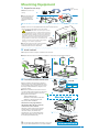
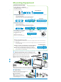
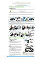
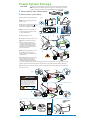
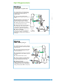
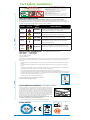
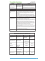
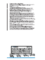
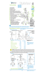
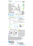
Features - SV22-92011
- SV22-92012
- SV22-92013
- SV22-92025
c
1 Riser
2 Notebook Enclosure
3 Worksurface
4 Electronic Autolock Drawer
5 Tilting Keyboard Tray and Wrist Rest
6 Right/Left Mouse Tray and Holder
7 Cable Management
8 Riser Lift Brake
9 Locking Front Casters
10 Scanner Holder Bracket
11 Ergonomic Rear Handle
12 Storage Basket
13 Power System - 220-240VAC, 50 Hz
d
e
b
a 55 Ah Battery
b 3 AC Outlets (300 Watts total)
c Remote User Interface (RUI)
d StyleLink Software CD & Cable
e Coiled Power Cord
a
StyleView
powered carts
provide electrical
AC power for
mobile point of
care computing
equipment in
a healthcare
environment.
Please read all parts of this guide. When set-up is complete,
do not discard this guide. The guide should be filed in a secure
place for future reference.
Cart Specifications - For Power System Specifications see page 11.
Range of motion
Vertical Adjustment Range: 20" (508 mm)
STAND
SIT
Tilt: ±15° Viewing Angle
Based on a 10" High x 1/2"
deep Notebook
Keyboard Tray Tilt: -12°
Weight capacities
Notebook
6-18 lbs
2.72-8.26 kg
4 lbs
1.8 kg
Worksurface
2.5 lbs
1.1 kg
CPU Holder
25 lbs
11 kg
Keyboard Tray
2.5 lbs
1.1 kg
Mouse Holder
.5 lb
.23 kg
Scanner Holder
.5 lb
.23 kg
Basket
5 lbs
2.3 kg
Drawer
17"
432 mm
Maximum
Notebook Size
< 1.5"
< 38 mm
12.5"
318 mm
CAUTION: The lift brake locks the vertical lift of riser during normal use but it DOES NOT increase
load capacity. DO NOT load riser with equipment totalling more than the maximum weight
capacity specified by Ergotron. Ensure optimum lift function by testing and if necessary, re-adjusting
tension whenever the weight mounted to the riser changes (i.e., equipment is removed or added). See
"Set Riser Lift Tension" adjustment instructions in step 7 on page 5.
Dimensions
Riser at Full Height
Riser in Lowest Position
v
157 mm
50.8"
1290 mm
70.5"
1791 mm
44"
1118 mm
v
24"
533 mm
610 mm
18"
18"
457 mm
21"
566 mm
457 mm
533 mm
For more information
on this or other Ergotron
products, visit our website:
22.3"
28"
711 mm
38"
965 mm
1
www.ergotron.com
888-SV-22FN-00 rev C
Mounting Equipment
1
• 9/16"
• 3/8" (10mm)
Prepare for cart set-up.
a Gather tools for cart
set-up.
a
b To prevent the riser
from moving during
set-up, lock riser by
pushing the lift brake
down.
b
2
2
1
Remove anchor screws connecting riser to tower.
a Make sure riser is locked (lift brake down), then remove the two
capped screws anchoring the riser to the tower.
WARNING: The riser can move up on its own
very quickly when a counter-balancing force is
removed! Therefore, always lock the riser down with
the lift brake when adding or removing equipment
and when removing or inserting the anchor screws
which secure the riser to the tower during shipping. Failure to lock the riser at such times can
result in serious personal injury and possible
damage to cart and/or equipment.
tower
a
riser
b Save the screws and caps in the provided
bag to be used if the riser needs to be
anchored to the tower at a later time.
3
b
Attach notebook
a Lift up work surface and place notebook into enclosure.
b Attach adhesive velcro to bumpers and adhere to enclosure to keep notebook in place.
b
a
4
Personalize autolock drawer code.
a
Four AA
a Unlock drawer with master key (identical
duplicate keys are provided). Pull drawer open
to access battery box; remove box cover; insert
the four provided AA batteries. Replace cover
and close drawer.
b Remove the Master Code sticker located
near the number pad and place it in the box at
right for safe keeping and future reference.
c
b
Program Personal Code:
Master Code
1 Enter Master Code
2 Press 3 and 5 at the same time
3 Enter a new personal code any series of five numbers
The drawer is now programmed to
unlock when either the personal code
or the master code is entered.
The drawer remains unlocked for 2 minutes
and the number 5 remains lighted. At the
end of two minutes, the drawer automatically locks. You can manually lock the
drawer at any time by pressing 1 and 2 on
the number pad simultaneously.
*
Store this guide along with the master keys in a secure
place to prevent unauthorized access to autolock drawer.
2
c
1
2
3
4
5
888-SV-22FN-00 rev C
8
Mounting Equipment
)
Autolock Drawer Tips
To Unlock Drawer - 3 methods
• Key - turn counter clockwise 1/8 turn
• Enter Master Code
• Enter Personal Code
Personal Code
Master Code
To Program Personal Code
1 Enter Master Code
2 Press 3 and 5 simultaneously (while blinking)
3 Enter new code - any series of five numbers
New Code
Master Code
To Erase Personal Code
1 Enter Master Code
2 Press 3 and 5 simultaneously (while blinking)
3 Press 1 and 2 on number pad at the same time
Master Code
To Lock Drawer - 2 methods
• Press 1 and 2 on number
pad simultaneously
or
• Wait two minutes for
drawer to lock automatically
Manual
Auto
Autolock Drawer Troubleshooting
• Number pad numbers are dark
-Touch anywhere on number pad to activate back-light, (drawer remains locked until you
enter valid code)
-If touching number pad does not activate back-light, batteries may need to be replaced,
see instructions 4a.
• Number 4 on number pad is blinking = Low Voltage Warning
Low Voltage Alert
-Batteries may need to be replaced, see instructions 4a.
• Drawer won’t open when Personal Code is entered
-Test system by entering Master Code. If drawer doesn’t unlock,
replace batteries as instructed 4a.
5
Mount keyboard accessories & reference card
a Apply double-sided tape to bottom of wrist rest and place on tray.
b Use hook & loop tape to fix keyboard on tray.
c Snap mouse pouch on right or left side of tray.
d Attach reference card to handle with cable tie.
d
Working
Moving
customize - to your size
1 Set monitor screen about one
stow - before you go
1 Look where you’re going: unlock
inch above eye level - unlock brake
to allow riser to lift or lower as shown
below.
lift brake and lower riser for an unobstructed view.
2
Tilt screen for comfortable viewing and to reduce eye and neck strain.
Tuck away open trays and return
mouse, scanner and other accessories
to their places.
3 Pull keyboard tray forward and
3
2
Lock lift brake to keep riser down
and equipment secure while cart is in
motion.
position mouse tray and mouse pouch
on right or left, as needed.
4
4
5
Work with elbows bent at about
90° to minimize muscle strain.
Unlock both front casters.
Push cart from rear with elbows
bent at about 90° to maximize control
and minimize muscle strain.
5
If the riser moves up and down
with difficulty, or if it drifts out of set
position, consult the product manual
for adjustment information.
6 Don’t run out!
Before moving, make sure cord is
unplugged from outlet and hooked
to basket for safe travel. Remember,
charge battery fully 100% every day!
6 Stay in charge!
Powered carts should be plugged into
outlet as often as possible to keep battery charged and computer running.*
1
2
5
3
4
2
5
6
6
1
3
4
“A charged battery is a happy battery!”
Riser Lift Brake Operation
*
Power Cart Users: refer to the other side of this
card to learn how to respond to RUI messages about
the status of your battery charge!
For more information on this or other
Ergotron products, visit our website:
www.ergotron.com
Up = Unlocked
Down = Locked
888-24-039-00revA
a b
Sterile
Alcohol Prep
c
*
For optimum bonding, clean all surfaces with alcohol
wipe and allow to dry for one minute before applying tape.
6
Route Cables
a
Lift riser to highest position and pull the keyboard/mouse tray out as far as it will go.
b Lock down lift brake.
*
Routing cables with the cart
components fully extended helps
ensure sufficient slack for unrestricted
movement during use.
C
888-SV-22FN-00 rev C
3
Cable Routing
6 Route Cables
c Connect one end of the RUI cables to the
RUI that is mounted to the riser. Connect
grey cable to grey jack and black cable to
black jack.
c
d Remove side covers of cable box mounted
under the drawer. Route the RUI and computer cables
down riser and into the cable box. Route keyboard and mouse
cables into the cable box. Use cable box to store excess cable and
power bricks.
e Route cables out of cable box to cable channel. Bundle the length of
cables from cable box to cable channel inside one 20" (508 mm)
length of the provided flexible tubing.
f
Route the RUI cables along with the equipment
power cords, down the channel to the outlets
under the front cover. Since outlet configurations vary from country to country, refer to
the Outlet Configuration Table, below to
identify instructions that relate specifically to the outlet on your Cart. Connect the RUI cables and plug-in the
power cords according to the
Outlet Configuration Table.
d
f
e
CAUTION: Route cables
on Cable Channel (right)
side of Cart only. Do not
store power brick inside base
covers. Storing power brick
inside base covers may damage electrical wires
and interfere with riser operation, resulting in
damage to both Cart and mounted equipment
or injury from electrical shock.
g Close cable channel around wrapped cables
and replace cable box side covers. Move riser
up and down to ensure cables are routed properly and movement of the riser is not restricted.
Adjust if necessary.
20"
(508 mm)
Leave
about 20" (508
mm) of slack in
cables between
the cable box
and the cable
channel.
*
g
CAUTION: Observe maximum watt ratings,
do not connect equipment that will draw beyond the
300 watt capacity of the power system in your StyleView
Cart. Failure to comply with this safety hazard may result
in equipment damage.
Outlet Configuration Table
China
220-240VAC
50 Hz
(Step 6f)
An Outlet
box cover
is not
required on
this system
Europe,
Australia,
and
New
Zealand
2x
220-240VAC
50 Hz
8-32 x 1/4"
United
Kingdom
and
Singapore
220-240VAC
50 Hz
2x
8-32 x 1/4"
4
888-SV-22FN-00 rev C
8
Riser Lift Adjustment
7
a
a
Set riser lift tension.
Unlock riser (lift brake up).
b Move the riser up and down. If you feel
excessive resistance within the range of
motion, or if the riser does not stay in the
desired position, the lift tension should be
adjusted.
b
c
c
Remove tower cover.
d
Lift riser to highest position on tower.
e Turn tension nut up or down as needed.
f After adjustment, check lift tension by moving riser up and down (as described in step 7b). If
more adjustment is necessary, continue turning nut until the riser lift is satisfactory.
e
9/16"
d
IMPORTANT
Lift riser to highest position before making
any adjustments to the tension nut!
8
Increase Lift
Decrease Lift
turn toward PLUS sign
turn toward MINUS sign
Attach covers.
a
a Cover cables on riser.
b Attach tower cover.
c Attach top of riser cover.
d Lock riser cover.
b
c
d
Battery Charging Cycle
*
Do Not stretch coiled cord
further than 10 feet (3 meters),
damage to the cord may occur.
Charge Battery
9 FIRST
TIME BATTERY CHARGE
To charge the battery for first time and/or
to charge the battery after a period of storage
a Plug power cord into appropriate wall outlet and verify that the green "100" light is flashing
to indicate battery is charging. Continue to charge until light stops flashing and stays lit.
b Turn power system on by holding down the AC Outlet Power ON"
located on the RUI for 1 - 3 seconds. The Power light, the battery charge
indicator lights and the alarm enabled light will come on.
a
C
888-SV-22FN-00 rev C
b
5
Battery Charging Cycle
10
Tracking battery power - the Remote User Interface (RUI)
The RUI will alert you to the percentage of charge remaining in the cart battery with a series of
steady or flashing red, yellow or green lights, and an alarm that can be set to beep or remain mute.
Refer to chart for common RUI messages and how to respond to each. Remember, the battery
needs to be charged to 100% every day, and you can use the cart while charging, so plug-in cord as
often as possible to avoid running out of power!
NOTE: Put monitor in power save mode to optimize battery run time.
Power
Light
Power
Button
Alarm
Light*
Light On
Activated
- Beep
Alarm
Button
Light Off
Disabled
- Mute
Battery charge cycle
understand and respond to RUI alerts
Alert
RUI Display
Visual
Audio
100% Light Flashes Green
Charge Status
Response
Charging
Allow battery to
continue charging
until the 100% light
stops flashing.
Power Cord is
plugged-in
100%
Full
All Lights Steady Green
Between
50% and
30%
30% – 50% Lights Yellow
Alarm Beeps *
You can use cart
while charging.
When 100% light
stops flashing the
battery is fully
charged and the cart
can be unplugged.
Plug-in power
cord and charge
to 100%!
You can use cart
while charging.
30%
or less
30% Light Flashes Red
Alarm Beeps *
0%
No Lights
No power
available until
power cord is
plugged-in.
No Alarm
*
Frequent
operation of
the cart while
battery charge
levels are
below 30% will
significantly
reduce the life
of your battery.
* If the alarm is activated (green light is on), it will start beeping when the battery charge level drops to 50% and below.
Beeping will stop only when the charge empties to 0% or when the power cord is plugged-in for recharging. NOTE: If
the alarm light is off, the beeping has been disabled and the alarm is mute. For details on enabling and disabling alarm
contact Ergotron Customer Care.
11
StyleLink
a
a
Install StyleLink software
(after computer has been connected to power): place CD in
computer and follow set-up
instructions that appear on
display.
b
b
After software installation
is complete, connect one end
of USB cable to USB port on
computer.
c
c Route USB cable down channel at side of tower.
d
Connect oposite end of USB cable
to USB port located on Cart base in
front of power outlets.
NOTE: When StyleLink software is downloaded and
used, your battery warranty period is 1 year.
d
*
See help file in the
StyleLink software
for more detailed
information.
6
888-SV-22FN-00 rev C
8
Set-up is complete - your Cart is ready to go!
The following pages contain important guidelines for safe operation and maintenance
of the SV Cart and the power system.
Refer to our website for more information about the StyleView Cart and
other Ergotron products. www.ergotron.com
Battery Replacement
Replacing Battery
WARNING: Only Ergotron-specified batteries may be used in the StyleView Power System.
Please call customer care for details.
Do not replace the batteries while cart is located in an oxygen rich or hazardous environment.
Sparking may occur.
*
Follow LONG TERM Storage Steps (a) - (i) to remove existing battery then continue with steps (k) - (p)
below, to connect the replacement battery.
k After removing battery from cart, lift out of tray. Recycle battery or contact Ergotron for proper
battery disposal guidelines.
l Place new battery in tray; insert battery into cart.
k
l
LEAD
BATTERY
m Remove boot to expose Red (+) connector. Connect Red (+) lead to battery with terminal bolt and
wrench. Connect Red lead BEFORE Black lead! Be careful not to contact tools between terminals on
battery and metal chassis. Place boot on Red terminal.
n Remove boot to expose Black (-) connector. Connect Black (-) lead to battery with terminal bolt and
wrench. Connect Black lead AFTER Red lead! Be careful not to contact tools between terminals on
battery and metal chassis. Place boot on Black terminal.
m
n
Black
Black
Red
Red
10mm
10mm
o Plug-in cord reel cable.
p Attach cover to cart and tighten screws.
o
1/8"
p
Power System Storage
Power System Storage
a
- SHORT TERM
*
If the Power System will be idle for up to three
months, the battery should be fully charged before
storage and recharged during storage.
If the Power System will be idle for 3 months or
more, the battery should be removed from the cart
and stored, follow LONG TERM Storage instructions!
b
a Turn off all mounted equipment.
b Plug power cord into appropriate wall outlet
to fully charge battery to 100% (all RUI indicator
lights will be illuminated). Power system must be
fully charged before storing!
c
c
Once battery has been charged to 100%, turn
power system off by holding down the AC Outlet
Power
on the RUI for 1 - 3 seconds. Power
light will shut off.
d Leave power cord plugged into appropriate wall outlet if possible. If wall outlet is not
available for cart storage, remove front cover,
disconnect RUI cables from jacks located on side
of outlet box, and replace cover. If cart is not
plugged into a wall outlet while stored, recharge
battery once a month.
C
888-SV-22FN-00 rev C
NOTICE: Warranty on fully charged batteries left in an unused state for more than three
(3) consecutive months is automatically void.
Warranty on fully discharged batteries left in an
unused state for more than three (3) consecutive
days is automatically void.
7
Power System Storage
- LONG TERM
*
If the Power System will be idle for 3 months or more, the battery should be
removed from the cart and stored, follow steps below. If the Power System will
be idle for less than 3 months, follow SHORT TERM storage instructions!
Four AA
1 Remove batteries from Autolock drawer.
2 Remove power system battery.
b
a
a Turn off all mounted equipment.
b Disconnect Power System from
power source.
c Turn power system off by holding
on
down the AC Outlet Power
the RUI. Power light will shut off.
c
d
d Remove front cover and disconnect RUI cables from jacks located
on side of outlet box.
e
Remove battery cover.
e
1/8"
f Unplug cord reel for better access.
g Remove protective boot from
Black (-) lead. Be careful not to
contact tools between terminals
on battery and metal chassis. Use
wrench to remove terminal bolt
from Black (-) lead. Slide boot over
exposed connector.
h Repeat step (g) for Red (+) lead.
Be careful not to contact tools
between terminals on battery and
metal chassis.
f
i Remove battery and store in cool,
dry area while Cart is out of use.
Optimal storage temperature is
15°C/59°F. Battery votage should
be checked every three (3) months. If voltage drops below 12.5VAC, fully recharge battery. Contact
Ergotron Customer Care for information about how storage might impact the battery warranty.
j Gently push boot-covered leads back into the cavity left by the removed battery and replace battery cover to base.
g
Black
WARNING
Red
10mm
Disconnect power before entry.
Only authorized personnel may
service this equipment. Read
and understand operating instructions before opening unit
or replacing battery.
Black
Red
h
10mm
i
j
1/8"
8
888-SV-22FN-00 rev C
8
Cart Safety Guidelines
Equipment Changes and Cart Transfers
Always anchor the riser to the tower BEFORE making changes to cart such as:
• removing or adding equipment
• preparing the cart for transit to another site
See step 2 on page 2 for more information.
Cleaning and Maintenance
The following procedures are not guaranteed to control infection. The hospital infection control administrator or epidemiologist should be consulted regarding cleaning procedures and processes.
To avoid risk of electric shock, do not expose electrical components to water, cleaning
solutions or other potentially corrosive liquids or substances.
Do not immerse Cart or Cart components in liquid or allow liquids to flow into the Cart.
Wipe all cleaners off surface immediately using a damp cloth. Thoroughly dry surface after
cleaning.
Do not use flammable cleaners on Cart surfaces due to close proximity of electrical
power and equipment.
All paints and plastic Cart components will withstand cleaning by most commonly used, diluted, nonabrasive solutions such as quaternary ammonia compounds, ammonia enzyme cleaners, bleach or
alcohol solutions.
• Pen and permanent and dry erase markers can be removed with 91% isopropyl alcohol and a soft
cloth.
• Iodine stains can be removed with commonly used cleaners and a soft cloth.
• Never use steel wool or other abrasive materials that will damage the surface finish.
It is recommended that any cleaning solution be tested on a small, inconspicuous area to ensure
surface is not harmed.
Adjustment, Service, Replacement - DO NOT attempt to adjust, service or replace any part of the StyleView Cart unless directed to do so through Ergotron-approved documentation (i.e. installation instructions). Only Ergotron, Inc. or an Ergotron-certified entity may adjust, service
or replace StyleView Cart components. If any component on the Cart is missing or damaged, the Cart
must not be used, contact Ergotron Customer Care immediately to request a replacement part.
Cables - Keep cables neatly organized on the Cart (a variety of solutions are provided with
your cart for this purpose). Excess cables should be routed away from moving components with cable
clips. Review Cable Routing section of this guide, or contact Ergotron Customer Care for more information.
Casters - Check casters periodically to make sure they are clean and free of debris that would
prevent smooth travel. Avoid moving Cart across uneven, dirty or damaged surfaces.
Customer Equipment- Make sure equipment is balanced and mounted securely to Cart. Do not reposition Cart components on riser or tower unless instructed to do
so in the installation instructions. Moving Cart components too high or too low on the Riser
may create an unstable condition, leading to equipment damage or even personal injury.
Contact Ergotron Customer Care for information about moving Cart components.
Cart Stability - When moving cart, the riser MUST be in the lowest position and the lift
brake MUST be locked to protect against possible tipping. Failure to lock the riser in the lowest position
with the lift brake may result in personal injury or equipment damage.
Safety Alerts Associated with this Product
The following Warnings/Cautions appear in this reference guide or on the cart:
NOTE: Failure to adhere to these guidelines may result in equipment damage or personal injury.
CAUTION: The lift brake helps stablilize the worksurface and keyboard tray during normal
use but it DOES NOT increase load capacity. DO NOT load riser with equipment totalling more
than the maximum weight capacity specified by Ergotron. Ensure optimum lift function by testing and if necessary, re-adjusting tension whenever the weight mounted to the riser changes
(i.e., equipment is removed or added). See "Set Riser Lift Tension" adjustment instructions in step
7 on page 5.
CAUTION: Do not operate StyleView Cart with missing or damaged components! Do not
remove, modify or substitute Cart components without consulting Ergotron. If you encounter
problems with Cart installation or operation, contact Ergotron Customer Care.
CAUTION: DO NOT overtighten fasteners. Overtightening may cause damage to your
equipment.
CAUTION: Riser is under spring tension. Rapid rise or fall of riser can occur prior to
counterbalancing. Lock riser down with Brake before removing Riser Anchor Screws or loading/
unloading equipment. Do Not put yourself in path of movable riser or mounted components until
riser is properly counterbalanced. Failure to comply with this caution may result in equipment
damage or personal injury.
CAUTION: DO NOT loosen, tighten or remove any other nuts or bolts on the riser or top of
tower. Tampering with nuts or bolts may result in an unstable Cart, leading to equipment damage
and/or personal injury.
WARNING: Unlock Lift Brake before moving work surface! Moving work surface while Lift
Brake is locked may cause serious damage to Lift Engine.
WARNING: In the event that repair of the StyleView Cart is needed, contact Ergotron Customer Care immediately. Cart repair can only be performed by Ergotron, Inc. or by an Ergotron
authorized agent.
CAUTION: Route cables on Cable Channel (right) side of Cart only. Do not store power brick
inside base covers. Storing power brick inside base covers may damage electrical wires and interfere with
riser operation, resulting in damage to both Cart and mounted equipment or injury from electrical shock.
C
888-SV-22FN-00 rev C
9
Cart Ergonomics
Working
customize - to your size
1 Set monitor screen about one
inch above eye level - unlock brake
to allow riser to lift or lower as
shown below.
T
T
2 Tilt screen for comfortable
viewing and to reduce eye and neck
strain.
t
2
3
3 Pull keyboard tray forward and
position mouse tray and mouse
pouch on right or left, as needed.
4
4
5
Work with elbows bent at about
90° to minimize muscle strain.
5 If the riser moves up and down
with difficulty, or if it drifts out of
set position, consult the product
manual for adjustment information.
6
1
6 Stay in charge!
Powered carts should be plugged
into outlet as often as possible to
keep battery charged and computer
running.*
Moving
stow - before you go
1 Look where you’re going: unlock
lift brake and lower riser for an unobstructed view.
1
2 Tuck away open trays and return
mouse, scanner and other accessories to their places.
3 Lock lift brake to keep riser down
and equipment secure while cart is in
motion.
4
5
2
6
Unlock both front casters.
Push cart from rear with elbows
bent at about 90° to maximize control and minimize muscle strain.
6 Don’t run out!
Before moving, make sure cord is
unplugged from outlet and hooked
to basket for safe travel. Remember,
charge battery fully 100% every day!
10
5
3
4
888-SV-22FN-00 rev C
8
Cart Safety Guidelines
$!.'%2
$/./42%-/6%4()3,!"%,
ELECTRICAL CORDS CAN BE HAZARDOUS
-ISUSE#AN2ESULTIN&)2%OR$%!4(BY%,%#42)#!,3(/#+
0LEASE2EADAND&OLLOW0RODUCT-ANUAL)NSTRUCTIONS
4()3)3!0/,!2):%$#/2$(/30)4!,'2!$%/.,9
./4%'ROUNDING2ELIABILITY#AN/NLY"E!CHIEVED7HEN
THE%QUIPMENT)S#ONNECTED4O!N%QUIVALENT2ECEPTACLE-ARKED
h(/30)4!,/.,9v/Rh(/30)4!,'2!$%v
s)NSPECT#ORD4HOROUGHLY"EFORE%ACH5SE$/./453%)&$!-!'%$
s$O.OT0LUG-ORE4HAN30%#)&)%$.5-"%2/&7!443)NTO0OWER3YSTEM
s$O.OT2UN#ORD4HROUGH$OORWAYS(OLESIN#EILINGS7ALLSOR&LOORS
s&5,,9).3%240LUG)NTO/UTLET
s$O.OT2EMOVE"ENDOR-ODIFY!NY-ETAL0RONGSOR0INSOF#ORD
s$O.OT5SE%XCESSIVE&ORCETO-AKE#ONNECTIONS
s+EEP!WAY&ROM7ATER$/./453%7(%.7%4
s+EEP#HILDREN!WAY&ROM#ORD
s$O.OT0LUG#ORDINTO!N%XTENSION#ORD
s!6/)$/6%2(%!4).'5NCOIL#ORDAND$O.OT#OVER)T7ITH!NY-ATERIAL
s$O.OT$RIVE$RAGOR0LACE/BJECTS/VER#ORD$O.OT7ALK/N#ORD
s'2!300,5'TO2%-/6%&2/-/UTLET$O.OT5NPLUG"Y0ULLING/N#ORD
Hazard Symbols Review
The Meaning of Symbols appearing in this Guide, on the Cart or on the Power System
These symbols alert you to a safety condition that demands your attention. You should be able to
recognize and understand the significance of the following Safety Hazards if you encounter them on
the Cart or within Cart documentation such as this Set-up Guide.
Color
Signal
Word
Level of Hazard
DANGER
Indicates an imminently hazardous situation which, if not
avoided, will result in death or serious injury.
Symbol
Red
Indicates a potentially hazardous situation which, if not
Orange
WARNING avoided, could result in death or serious injury.
Yellow
CAUTION avoided, may result in minor or moderate injury.
None
CAUTION tially hazardous situation which, if not avoided, may
Indicates a potentially hazardous situation which, if not
Used without the safety alert symbol indicates a potenresult in property damage.
Red,
Orange
or
Yellow
Electrical
Indicates an impending electrical hazard which, if not
avoided, may result in personal injury, fire and/or death.
Power System Specifications - 220-240VAC/50 Hz power system
SV22-92011
SV22-92012
SV22-92013
SV22-92025
Input: 220-240VAC/50 Hz, 2.7A
Output: 230VAC/50 Hz
The StyleView AC Power System (SPS) allows your power supply to travel with the cart. The Power System is integrated in the base
of the cart and comes standard with a battery, true sine wave inverter, ATS, RUI, charger, isolation transformer, outlet box and
power cord.
• True Sine Wave Inverter (TSW): designed to ensure satisfactory operation of Power Factor Corrected devices like Flat Panel
Monitors.
• Automatic Transfer Switch (ATS): allows connected computer equipment to switch to “house” power when charging the
battery.
• Remote User Interface (RUI): Located near worksurface, allows power system output to be turned on or turned off, allows
monitoring of battery charge left, and provides low battery charge audible alarm.
• 55Ah Sealed Lead Acid, Absorbed Glass Mat, Valve Regulated & Recombinant Gas Type, 12VDC battery.
• The recommended cart storage temperature is 15°C (59°F). At this temperature, the 55Ah battery’s age-related capacity loss
is minimized. The minimum storage temperature is -20°C (-4°F) and the maximum storage temperature is 50°C (122°F). The
recommended humidity range for storage is 0-95% rH.
• The cart and power system are certified to EN 60601-1.
For more information on this or other Ergotron products,
visit our website: www.ergotron.com
-20 °C
- 4 °F
50 °C
122 °F
Relative
Humidity 0-95% rH
Range
FCC Compliance Statement - Cart and Autolock Drawer
The Autolock drawer has been tested and found to comply with the limits for
a Class A digital device, pursuant to part 15 of the FCC Rules. These limits are
designed to provide reasonable protection against harmful interference when
the equipment is operated in a commercial environment. This equipment
generates, uses, and can radiate radio frequency energy and, if not installed
and used in accordance with the instruction manual, may cause harmful
interference to radio communications. Operation of this equipment in a
residential area is likely to cause harmful interference in which case the user
will be required to correct the interference at his own expense.
Changes or modifications not expressly approved by Ergotron, Inc. could
void the user’s authority to operate the equipment.
Please contact Ergotron for complete EMC compatibility information.
Product Marks
LEAD
BATTERY
C
888-SV-22FN-00 rev C
11
visit our website:
Troubleshooting
Symptom
www.ergotron.com
Probable Cause
Improper riser
counterbalance.
Riser moves up or
down too easily or with
difficulty; or equipment
Mounted equipment
on riser does not stay
exceeds weight capacity.
in desired position.
Solution
Follow "Set Riser Lift Tension" Adjustment
procedure in step 7 on page 5.
Compare weight of mounted equipment to
recommended weight capacities in specifications
section.
Contact Ergotron Customer Care: North America
1-800-888-8458; Europe +31 (0)33-45 45 600
Symptom
1) The lights on the
Remote User Interface
(RUI) will not illuminate.
2) The Cart Outlet
box will not power my
equipment.
3) My problem cannot
be solved with this
guide.
Solution
a) Press and hold the On/Off switch located at the left side of the RUI. Verify
the small green light above the RUI On/Off switch illuminates along with
one or more of the battery charge indicator lights. If multiple lights on the
RUI do not illuminate continue to the next step.
b) Verify the black and grey communications cables are not damaged
and are seated properly by lightly tugging on them at the base of the RUI.
Repeat step a).
c) Pull off the front panel and verify the black and grey communications
cables are not damaged and are seated properly (by lightly tugging on
them) in the correct jacks located at the side of the Cart Outlet box. Replace
cover and Repeat step a).
d) Contact Customer Service USA: 1-800-888-8458 or Europe +31 (0)33-45 45 600
a) Verify RUI is illuminated and that the equipment power cords are properly
connected to the Cart Outlet box. If the RUI is not illuminated try troubleshooting problem #1 before continuing on to step b).
b) Disconnect all equipment from the cart outlets. Use an outlet tester to
verify the outlets are able to correctly supply power. Keep the outlet tester
plugged into one of the outlets while troubleshooting.
c) Plug the cart into an external, appropriately rated powered outlet.
d) Attempt to turn on the RUI. Press and hold the On/Off switch located
at the left side of the RUI. Verify the small green light above the RUI On/Off
switch illuminates and that the outlet tester verifies the outlets are able to
correctly supply power. If the outlet tester does not verify the outlets are
able to correctly supply power continue to the next step.
e) Verify the Cart Outlet box cord is properly connected to the power
module. Then try step d).
f ) Unplug the cart from the external powered outlet and remove the battery
cover to verify the cord is properly connected to the power module plug.
Plug the cart into an external, appropriately rated powered Outlet. and try
step d).
g) Contact Customer Service (USA: 1-800-888-8458 or Europe +31 (0)33-45 45
600) for further troubleshooting instructions.
a) Contact Customer Service USA: 1-800-888-8458 or Europe +31 (0)33-45 45 600
Recommended Periodic Inspection and Maintenance
Component
Autolock Drawer
Batteries
1
Action
Replace 4 ea AA
batteries1
How often
Replace when
keypad #4
flashing
By whom
Any user
When instructed
by StyleLink or
when battery
runtime is ½ of
original runtime
IT personnel
Power System SLA
battery
Replace lead acid
battery1
Casters
Inspect for wear and
debris
Monthly
Any user
RUI, USB,
computer cables
Inspect for wear,
pinching, bad
connectors
Monthly
Any user
Coiled cord
Inspect for wear,
damage, or stretching.
Move attachment hook
to avoid dragging on
floor
Weekly
Any user
Maximum Load
Inspect to ensure
that maximum
recommended loads are
not exceeded
Daily
Any user
Please dispose of all batteries in accordance with local law
12
888-SV-22FN-00 rev C
8
C
888-SV-22FN-00 rev C
13