1
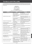
EXTRA 300 EXP
60 inch electric ARF assembly manual
1 Greetings and congratulations on your purchase of the Extreme Flight RC 60 inch EXTRA
300 EXP ARF. Loosely based on our favorite variant of the Extra, the 2 seat mid wing
Extra 300, we have taken numerous liberties with this design to produce an aircraft that is
both unique in appearance and flight ability. The designation EXP does not belong to a full
scale Extra, but rather stands for Experimental Progressive. This name was chosen due to
the fact that the Extra 300 EXP incorporates several new forward thinking design and
aerodynamic concepts. Having spent several months in development, flight testing and
refinement, we are very excited about the end result of our quest.
The Extra 300 EXP incorporates carbon fiber and G10 composites into the structure of the
airframe, resulting in a lightweight, yet twist free structure capable of handling extreme
aerodynamic loads. Carbon and G10 are used in high stress areas such as the landing gear
mounting structure and fuselage longerons to provide enormous strength and durability.
A true piece of carbon fiber art, the landing gear is airfoiled and has just enough "give" to
cushion those not so perfect landings. The removable wing panels are mounted on a
carbon fiber wing tube and are fastened to the fuselage with nylon thumbscrews. The large
canopy (which is retained by a spring loaded hatch latch) has been moved forward to place
the tallest portion of the aircraft near the center of gravity, resulting in superior knife edge
performance.
All control surfaces are pushrod driven with short linkages and use ball links for slop free
actuation with no binding. Optional Side Force Generators are included and add to the
already generous side area, increasing yaw axis authority and adding stability in all angles
of sideslip. Expertly painted fiberglass cowl and wheel pants and 2 gorgeous high visibility
Ultracote color schemes add the finishing touches and make this an airplane that you will
be proud to show up at the flying field with. The combination of these unique elements add
up to an aircraft that pushes the boundaries of modern aerobatic flight.
If repairs become necessary, the Ultracote colors used on the Extra 300EXP are as follows:
Blue/white/red color scheme: Midnight Blue, White, True Red
Red/white/black color scheme: True Red, White, Black
Extreme Flight R/C reserves the right to alter the assembly process at any time. While we
do our best to update the manuals, sometimes there are minor changes in the process of the
build. If you have any questions regarding assembly please contact us before moving
forward.
2 Box contents
3 Tips for Success:
1. Before starting assembly, take a few minutes to read the entire instruction manual to
familiarize yourself with the assembly process.
2. Please take a few minutes and go over all the seams on the aircraft with a covering iron
on a medium heat setting.
3. Use a fresh bottle of thin CA with a fine glue tip when attaching the CA hinges. This
will ensure that the proper amount of CA wicks into the hinge and surrounding balsa wood
and creates a proper bond between the wood and hinges. We are big fans of the Mercury
line of adhesives as well as the glue tips provided by them.
4. Apply a couple drops of CA to high stress areas such as anti-rotation pins, landing gear
mounts, servo trays and motor box joints .
5. All of the G10 control horns are the same with the exception of the elevator horn. Its
base has been shortened to fit the depth of the elevator.
6. When applying decals, first clean the area where the decal will be applied with alcohol.
Mist the area lightly with Windex or Rapid Tack before applying the decal which will allow
you to properly position it, then use a rubber squeegee to push all of the liquid from under
the decal. This will result in very few air pockets trapped under the decal.
7. Take the time to properly balance and trim your aircraft and set up rates and
exponential values. Your flying experience will be greatly enhanced by doing this.
*Please note: The Extra assembles in the exact same manner as the 60 inch Edge. As a
result some of the photos in this manual will be of the Edge if we determined they better
illustrated the assembly step.
4 Items needed for completion
-Masking tape.
-Hobby knife with #11 blades.
-Razor saw.
-Hobby sealing iron.
-Thin and medium CA. We highly recommend Mercury M5T thin and M100XF medium
formulas as well as the Mercury glue tips.
-30 minute epoxy. The new Mercury Adhesives Epoxies have worked very well for us.
-Denatured alcohol.
-Paper towels.
-Blue Loctite.
-Electric drill with an assortment of small drill bits.
-Small flat head and Phillip's head screw drivers.
-Standard and needle nose pliers.
-Metric balldriver or allen key set.
-Sanding block and sandpaper.
-4 mini metal geared servos. All flight testing was performed with Hitec HS-5245MGs and
we strongly recommend the use of these high quality servos.
-Dubro Long Super Strength servo arm set. (Dubro part #670 for Futaba, #671 for JR and
#672 for Hitec).
-Torque 4016T/500 Brushless Outrunner or Hacker A50-14XS v2 Outrunner motor.
-Airboss Elite 80 Amp ESC.
-5S-6S 3300-5000 mah LiPo battery.
- 16x8 prop for 5S operation, 15x6 for 6S operation.
-2-24" extensions for the 2 rear servos and 2-6"extensions to go between the receiver and
the aileron servo leads.
-Adhesive backed Velcro and Velcro strap for battery retention.
5 Let's begin!
1. Locate the 2 wing panels with ailerons as well as the 2 G10 aileron control horns and
base plates. Remove the covering over the slot for the aileron horn on the bottom of the
aileron with a sharp hobby blade. Make sure you are doing this on the bottom of the
aileron! Insert the horn into the base plate and into the slot in the aileron. Use a fine
tipped felt marker to trace the base plate.
2. Remove the control horn and scuff the portion that will be glued into the aileron with
sandpaper.
6 3. Use a sharp hobby blade to remove the covering 1/16 of an inch inside the line you
traced around the control horn base.
4. Mix up a batch of 30 minute epoxy and apply liberally to the slot in the aileron and to
the scuffed portion of the control horn that will insert into the aileron. Install the aileron
horn and base plate onto the aileron and wipe away any excess epoxy with a paper towel
soaked in denatured alcohol.
7 5. Remove the covering from the aileron servo location and make sure the hinges are
centered in their slots. Slide the aileron into position making sure the outer tip of the
aileron is flush with the wing tip. Apply a drop of CA at each hinge location on both the
top and bottom side of the wing. Use a fresh bottle of thin CA and a fine glue tip for best
results.
8 6. Before installing the aileron servo take a minute and apply some CA to the servo tray
and the anti-rotation pins.
7. Use the screws provided by the servo manufacturer to secure the aileron servo in the
designated location.
9 8. Locate the 2 threaded metal pushrods that are the same length and 4 ball links along
with 4-2mm screws, nuts and washers. Thread the ball links onto each end of the pushrods
and secure to the servo arm and control horn using the supplied hardware as shown in the
picture. Use the second longest set of servo arms included with the Dubro Long Super
Strength servo arm kit for the aileron linkages. (Dubro part #670 for Futaba, #671 for JR
and #672 for Hitec).
9. Repeat this process for the other wing half. When finished take a few minutes to go over
all of the seams in the covering with a sealing iron on a medium heat setting paying special
attention to stripe edges and ends. Clean the wing panels with a soft cloth and put them
away in their wing bags.
10 Fuselage assembly
10. First lets assemble the landing gear unit and bolt it to the fuselage. Locate the main
wheels, wheel pants, one piece carbon fiber landing gear, 4-3mm socket head cap bolts with
4 washers, 2 axles, 2 wheel collars, 2 large washers to fit the threaded portion of the axles,
and 2 nylon insert locknuts.
11. Place the wheel onto the axle and secure with a wheel collar. Place the threaded
portion of the axle through the hole in the carbon gear leg. Place a washer on the threaded
portion of the axle and screw the lock nut onto the axle, but do not tighten completely.
There is a slot pre-cut in the wheel pant to allow it to fit over the axle. Slide the wheel pant
into position over the axle and tighten the nut on the axle, taking care to make sure the
wheel pant is positioned properly. Repeat this process for the remaining wheel pant.
Again this is probably better explained in the following series of pictures.
11 12 12. Secure the landing gear to the fuselage by inserting a 3mm bolt into a washer, through
the carbon fiber gear and into the pre-installed blind nuts in the fuselage. Make sure to use
a drop of blue Loctite on each bolt to prevent them from backing out.
13 13. Next lets mount the horizontal stab. In preparation to do this we need to remove the
piece of balsa at the rear of the stab slot. The factory leaves this piece intact so that the
rear of the fuselage will remain true during the covering process and during transit. This
is a simple process using a hobby razor saw. First place a couple strips of masking tape on
the fuselage to give you a guide to cut by and to prevent the Ultracote covering from
tearing.
14. Use a razor saw to carefully make the cut, then sand smooth.
14 15. Locate the horizontal stabilizer/elevator assembly. Turn it upside down on your
building table and remove the covering over the right slot on the bottom of the elevator
where the elevator control horn will be installed. You may need to sand the bottom of the
horn so that it does not protrude through the top surface of the elevator. Insert the horn
into the base plate and into the slot. Trace around the base plate with a fine tipped marker.
Remove the horn and use a sharp hobby knife to remove the covering 1/16" inside the line
you traced. Scuff the portion of the control horn that will insert into the elevator with
sandpaper. Secure the control horn with epoxy just as you did with the aileron horns.
15 16. Slide the elevator onto the hinges in the stabilizer and secure with thin CA. Again a
fresh bottle of CA and a fine glue tip work best here
17. Insert the stabilizer into its slot and the carbon fiber wing tube into the fiberglass
sleeve. Use a ruler to insure that the stabilizer is centered in its slot and compare the
stabilizer to the wing tube to make sure it is properly aligned. Sand or shim the slot if
necessary to ensure proper alignment. Secure the stabilizer with CA.
16 18. Remove the covering over the slot in the lower right side of the rudder where the
rudder control horn will be installed as shown in the picture. Use caution and only remove
the covering from the lower portion so as to not penetrate the covering over the open
framework. Scuff the portion of the control horn that will glue into the surface and secure
the rudder control horn and base plate with epoxy.
17 19. Using the same process as with the ailerons and elevator, slide the rudder onto the
hinges and secure to the vertical stabilizer with thin CA.
20. Locate the carbon fiber tailwheel assembly in the hardware package. Secure the
tailwheel bracket to the bottom rear of the fuselage with the provided wood screws. Make
sure the pivot point of the assembly is over the hinge line of the rudder for best results.
Secure the tiller using the provided screw, but do not over tighten as the tiller should be
able to move on the screw as the rudder is deflected.
18 21. Place the tailwheel wire in the proper position, aligned with the rudder and lock into
place with the 2 set screws.
22. Use the hardware provided with the servos to install the rudder and elevator servos in
their respective location in the rear of the aircraft. From the pilot's perspective the rudder
servo mounts on the right side of the fuselage and the elevator servo mounts on the left side.
The elevator servo should have the output shaft toward the front of the aircraft while the
rudder servo output shaft should be toward the rear of the aircraft.
19 23. The rudder and elevator servo linkages assemble and are installed just like the aileron
linkages. For maximum control surface travel we highly recommend using the Long
Dubro Super Strength servo arms. (Dubro part #670 for Futaba, #671 for JR and #672 for
Hitec)
20 24. Lets prepare the Torque outrunner motor for mounting. First slide the provided collar
over the motor shaft and secure in place with the set screw. Place a drop of blue Loctite on
the threads of the set screw so that it will not back out.
25. Next secure the radial mount to the motor using the provided short Phillip's head
machine screws. Again be sure to use a drop of blue Loctite on each screw.
21 26. Secure the prop adapter using the 4 socket head cap bolts. Again blue Loctite should
be applied to each bolt.
27. Mount the Torque motor using the supplied 3mm black socket head cap bolts and
washers. The bolts are to be inserted into the blind nuts which are pre-installed in the
motor mount plate. Be sure to put a drop of blue Loctite onto each bolt to prevent them
from backing out. Be sure to add some CA to all motor box joints!
22 28. For quick, easy and accurate mounting of the cowl we recommend the following
method. Tear 4 short pieces of masking tape from a roll. Place each piece of tape on the
side of the fuselage so that each piece corresponds with one of the 4 cowl mounting tabs.
Use a fine tipped marker to mark the location of the center of each mounting tab. Roll the
tape back and slide the cowl into position. Install the Extreme Flight 63mm spinner onto
the motor shaft for reference and once satisfied with the cowl position roll the tape back
into place and secure the cowl. Use a 1/16" drill bit to drill a hole at the location of the dot
on each piece of tape. Remove the tape and secure the cowl with 4 of the included small
wood screws that have large heads. Very simple!
23 29. Use nylon cable ties or Velcro to secure the ESC to the bottom or side of the motor box
in front of one of the cowl inlet openings.
30. Place a strip of Velcro onto the battery tray and onto your battery and use a Velcro
strap around the battery and tray to prevent the battery from being ejected during high G
maneuvers. Mount your receiver on the portion of the battery tray that extends behind the
wing tube with Velcro.
24 31. If using the included Side Force Generators now is the time to mount them. There are
2 clear spacers the shape of the wing tip that are to be placed between the wing tip and
SFG to prevent them from rubbing against the aileron. Each SFG mounts using 2 3mm
bolts and 2 clear plastic washers. There are 2 laser cut holes in each SFG which
correspond with 2 laser cut holes in the tip of each wing. Insert the bolts into the plastic
washers and through the laser cut holes in the SFG and clear plastic spacer. Mount the
SFG onto the wing tip by inserting the 2 bolts into the pre-installed blind nuts in the tip of
the wing. Again apply a drop of blue Loctite to each bolt and be sure not to over tighten
the bolts which may crush the wood in the SFG.
25 Set-up and flying tips
The CG range for the Extra starts at 4 inches from the leading edge of the wing and
extends back to 4.75 inches, measured at the wing root. There is plenty of room on the
battery tray to move your battery to achieve this CG location. This is a safe place to start
and depending on your flying style you can adjust the position of the battery to alter the
CG to accommodate your preferences. For this type of aircraft where I am going to
predominantly fly aggressive 3D I typically set the airplane up with a neutral CG, meaning
that when the aircraft is flown inverted straight and level it requires no down elevator to
maintain altitude. If your flying style leans more toward precision aerobatics then I
recommend setting your CG using the 45 degree line test. Fly the aircraft from left to right
or right to left, whichever direction you are more comfortable with at 3/4 to full throttle.
Pull the aircraft to a 45 degree up line and establish this line and immediately roll the
aircraft inverted. Establish this line and let go of the elevator stick. Ideally the aircraft
will continue to track on that 45 degree line for several hundred feet before slowly starting
to level off. Adjust the position of your battery to achieve this flight condition. Once
satisfied with the location of your CG scribe a mark on the battery tray so that you can
position the battery in the same location each flight and achieve the same feel and flight
characteristics each flight.
I also highly recommend taking the time to properly set up your rates and exponential
settings. Setting up low rates for precision maneuvers and high rates for aggressive
aerobatics and 3D flight will allow you to experience the best attributes of the Extra 300
EXP or any aircraft for that matter. The recommended elevator set up will allow for close
to 80 degrees of throw! While this is great for really aggressive tumbling maneuvers,
positive and negative waterfalls and straight down dropping elevators, it can wreak havoc
on stable harriers, especially if you are just learning the maneuver. If your radio will allow
I suggest setting up 3 elevator rates or a flight condition that will allow you a rate for
precision flying, another for harriers and the majority of 3D maneuvers and a final rate
with as much travel as you can get for the crazy tumbles and flips.
Here are some suggested rates to get started with. These are the rates and exponential
values I feel comfortable with. They may feel awkward to you and if so please adjust to
your taste.
Elevator: Low rate-8-10 degrees; 15-20% Exponential
3D rate-45-50 degrees; 60-65% Exponential
Insane tumble rate: As much as possible! 65-70% Exponential
26 Rudder: Low rate-20 degrees; 45-50% Exponential
3D rate- As much as possible; 80-90% Exponential
Aileron: Low rate-15-20%; 40-45% Exponential
3D rate- As much as possible; 70-75% Exponential
Again, these are my preferences, adjust to suit your flying style and preferred feel.
The Extra 300 EXP is capable of performing the full range of known 3D and precision
maneuvers. It is also capable of performing all kinds of crazy aggressive maneuvers that
have yet to be named. A great deal of fun and excitement can be had by just gaining some
speed and pushing the sticks into new positions and seeing what happens! We've been able
to coax all kind of crazy gyroscopic maneuvers out of this airframe. One of my favorites is
to gain some speed and while on 3D rates and the "insane" elevator rate simultaneously
chop the throttle while giving positive snap inputs (full up, full left aileron, full left rudder).
Typically the EXP will perform 3 aggressive positive tumbles flipping over the wing tube
before it runs of out inertia. Experiment with different inputs and vary the speed of your
entry and see what happens. We can't wait to hear what you come up with! Be sure to get
it on video!
The included SFGs can also act as "training wheels" when learning the harrier maneuver.
They can help to stabilize the aircraft in high alpha flight and reduce pilot workload which
certainly helps when you are learning a new maneuver.
Another neat set-up to try is to mix the ailerons to act as spoilerons which move in
conjunction with your elevator. This mix commands both ailerons to raise as the elevator
raises. I typically use this mix at 100% and put it on a switch so I can turn it on when
needed and inhibit it when not needed. Some folks feel this type of mix is somehow taboo.
To them I say "open your mind"! Anything that enhances flight characteristics or allows
me to perform maneuvers that are otherwise not possible I am totally game to try! This
mix allows the most straight down dropping elevators you will ever encounter, insane walls
that gain no altitude where the tail of the aircraft is basically thrown under the fuselage
and the tightest KE spins I've ever seen. This mix is also another good training tool for
learning the harrier maneuver and by experimenting with the amount of spoileron to
elevator mix you can actually determine the angle of attack that the EXP will harrier in.
The best advice I can offer is to experiment, burn through lots of battery packs and above
all have fun! You are in possession of a completely capable airframe whose flying abilities
are only limited by your imagination. We have had a blast during the development and
testing stages of this aircraft and I sincerely hope the Extra 300 EXP provides you with as
much joy and excitement as it has for me. See ya at the flying field!
27