1
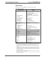
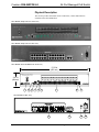
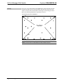
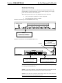
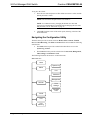
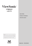
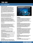
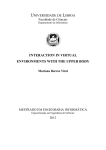
Crestron CEN-SWPOE-24 24-Port Managed PoE Switch Operations Guide This document was prepared and written by the Technical Documentation department at: Regulatory Compliance This product is Listed to applicable UL Standards and requirements by Underwriters Laboratories Inc. As of the date of manufacture, the CEN-SWPOE-24 has been tested and found to comply with specifications for CE marking and standards per EMC and Radiocommunications Compliance Labelling. Federal Communications Commission (FCC) Compliance Statement This device complies with part 15 of the FCC Rules. Operation is subject to the following conditions: (1) This device may not cause harmful interference and (2) this device must accept any interference received, including interference that may cause undesired operation. CAUTION: Changes or modifications not expressly approved by the manufacturer responsible for compliance could void the user’s authority to operate the equipment. NOTE: This equipment has been tested and found to comply with the limits for a Class B digital device, pursuant to part 15 of the FCC Rules. These limits are designed to provide reasonable protection against harmful interference in a residential installation. This equipment generates, uses and can radiate radio frequency energy and, if not installed and used in accordance with the instructions, may cause harmful interference to radio communications. However, there is no guarantee that interference will not occur in a particular installation. If this equipment does cause harmful interference to radio or television reception, which can be determined by turning the equipment off and on, the user is encouraged to try to correct the interference by one or more of the following measures: Reorient or relocate the receiving antenna Increase the separation between the equipment and receiver Connect the equipment into an outlet on a circuit different from that to which the receiver is connected Consult the dealer or an experienced radio/TV technician for help Industry Canada (IC) Compliance Statement This Class B digital apparatus complies with Canadian ICES-003. Cet appareil numérique de la classe B est conforme à la norme NMB-003 du Canada. The specific patents that cover Crestron products are listed at patents.crestron.com. Crestron, the Crestron logo and Crestron Toolbox are either trademarks or registered trademarks of Crestron Electronics, Inc. in the United States and/or other countries. UL and the UL logo, are either trademarks or registered trademarks of Underwriters Laboratories, Inc. in the United States and/or other countries. Other trademarks and trade names may be used in this document to refer to either the entities claiming the marks and names or their products. Crestron disclaims any proprietary interest in the marks and names of others. ©2012 Crestron Electronics, Inc. Crestron CEN-SWPOE-24 24-Port Managed PoE Switch Contents 24-Port Managed PoE Switch: CEN-SWPOE-24 1 Introduction ............................................................................................................................... 1 Features and Functions ................................................................................................ 1 Specifications .............................................................................................................. 2 Physical Description.................................................................................................... 3 Setup .......................................................................................................................................... 6 Network Wiring........................................................................................................... 6 CAT5 Wiring............................................................................................................... 6 Installation ................................................................................................................... 6 Hardware Hookup ....................................................................................................... 8 Configuration........................................................................................................................... 10 Accessing the Configuration Utility .......................................................................... 10 Navigating the Configuration Utility......................................................................... 12 Problem Solving ...................................................................................................................... 24 Troubleshooting......................................................................................................... 24 Reference Documents................................................................................................ 24 Further Inquiries ........................................................................................................ 24 Future Updates .......................................................................................................... 24 Appendix: Fast Ethernet and Gigabit Ethernet ....................................................................... 25 About Fast Ethernet................................................................................................... 25 About Gigabit Ethernet.............................................................................................. 25 Return and Warranty Policies .................................................................................................. 26 Merchandise Returns / Repair Service ...................................................................... 26 Crestron Limited Warranty........................................................................................ 26 Operations Guide – DOC. 7036C Contents • i Crestron CEN-SWPOE-24 24-Port Managed PoE Switch 24-Port Managed PoE Switch: CEN-SWPOE-24 Introduction The CEN-SWPOE-24 offers control system networking made easy, providing Crestron® guaranteed performance and reliability for a complete Ethernet network of touch screens, keypads, control processors, and other devices in a 2-space rack mount package. Rear panel connectivity with front panel indicators and controls provides an ideal form factor for use in a typical 19” equipment rack. Full IEEE 802.3af Power over Ethernet (PoE) is furnished simultaneously across all 24 ports, providing a centralized power source for numerous PoE powered devices and eliminating the need for additional power supplies and wiring. Dual Gigabit Ethernet uplink/stacking ports assure ample bandwidth for the 24 high-speed 10/100BASE-T ports. Its front panel management port enables mirroring of any rear port for easy monitoring and troubleshooting. Customizable front panel labeling makes it easy to designate each port with a friendly, descriptive name. Advanced configuration is enabled through an intuitive Web browser interface. Features and Functions • • • • • • • • • • • • • • Operations Guide – DOC. 7036C Rack-mount 24-port managed 10/100 Ethernet switch Full IEEE 802.3af Power over Ethernet (PoE) provided simultaneously across 24 ports Dual Gigabit Ethernet uplink/stacking ports All ports rear mounted for use in a typical AV equipment rack Front panel management port for easy troubleshooting Configured via simple to use Web browser interface SNMP monitoring and management Auto-discovery via Crestron Toolbox™ Layer 2 managed switching functionality 8.8 Gbps switching fabric (non-blocking) Auto-negotiation and auto MDI/MDIX capability Port configuration settings for speed and duplex Real time clock supports synchronization with Internet based time servers via NTP Custom front panel labeling using Crestron Engraver software 24-Port Managed PoE Switch: CEN-SWPOE-24 • 1 24-Port Managed PoE Switch Crestron CEN-SWPOE-24 Specifications Specifications for the CEN-SWPOE-24 are listed in the following table. CEN-SWPOE-24 Specifications SPECIFICATION DETAILS Ethernet Ports (24) 10BASE-T/100BASE-TX auto-sensing Fast Ethernet with PoE; (2) 10/100/1000BASE-T auto-sensing Gigabit Ethernet Network Standards IEEE 802.3, 802.3u, 802.3ab, 802.3af Topology Star Transmission Method Store-and-Forward Mac Addresses 8K addresses Memory Buffer 3 Mbits per device Switch Fabric 8.8 Gbps non-blocking Power Requirements 4.8 - 2.0 Amps @ 100-240 Volts AC, 50/60 Hz1, 2 Environmental Installation Location Indoor use only Temperature 32° to 104°F (0° to 40°C)3 Humidity 10% to 90% RH (non-condensing) Heat Dissipation 400 BTU/Hr Enclosure Chassis Metal, black finish, fan cooled, vented sides Faceplate Aluminum, black finish with polycarbonate label overlay Mounting Freestanding or 2U 19-inch rack mountable4, 5 (adhesive feet and rack ears included) Dimensions Height 3.56 in (90 mm), 3.47 in (89 mm) without feet Width 17.03 in (433 mm), 19.00 in (483 mm) with ears Depth 11.66 in (297 mm) Weight 9.1 lbs (4.1 kg) 1. Consideration should be given to the connection of the equipment to the supply circuit and the effect that overloading of the circuits might have on over current protection and supply wiring. Appropriate consideration of equipment nameplate ratings should be used when addressing this concern. 2. Reliable earthing of rack-mounted equipment should be maintained. Particular attention should be given to supply connections other than direct connections to the branch circuit (for example, use of power strips). 3. If installed in a closed or multi-unit rack assembly, the operating ambient temperature of the rack environment may be greater than room ambient temperature. Therefore, consideration should be given to installing the equipment in an environment compatible with the maximum ambient temperature specified by the manufacturer. 4. Installation of the equipment in a rack should be such that the amount of air flow required for safe operation of the equipment is not compromised. 5. Mounting of the equipment in the rack should be such that a hazardous condition is not achieved due to uneven mechanical loading. 2 • 24-Port Managed PoE Switch: CEN-SWPOE-24 Operations Guide – DOC. 7036C Crestron CEN-SWPOE-24 24-Port Managed PoE Switch Physical Description This section provides information on the connections, controls and indicators available on the CEN-SWPOE-24. CEN-SWPOE-24 Physical View (Front View) CEN-SWPOE-24 Physical View (Rear View) CEN-SWPOE-24 Overall Dimensions (Front View) 17.03 in (433 mm) 3.47 in (89 mm) 1 2 3 4 5 6 7 8 9 CEN-SWPOE-24 (Rear View) 10 Operations Guide – DOC. 7036C 11 12 13 24-Port Managed PoE Switch: CEN-SWPOE-24 • 3 24-Port Managed PoE Switch Crestron CEN-SWPOE-24 CEN-SWPOE-24 Overall Dimensions (Top View) 11.46 in (292 mm) 11.66 in (297 mm) Connectors, Controls & Indicators # CONNECTORS, CONTROLS & INDICATORS 1 ON / OFF DESCRIPTION (1) Rocker switch behind protective guard, turns main power on or off Indicates Power ON Indicates Power OFF 2 PWR LED 3 MGMT PORT MIRROR (LED and Button) (1) Recessed miniature push button and (1) green LED to enable or disable the port mirroring MGMT port MGMT (1) 8-pin RJ-45, female; 10BASE-T/100BASE-TX Ethernet port and IEEE 802.3af Class 0 PoE Power Sourcing Equipment output 4 Pin 1 Pin 8 (1) Green LED, indicates operating power supplied via main power input and unit is turned on PIN SIGNAL PIN SIGNAL 1 2 3 4 TX + TX RX + N/C 5 6 7 8 N/C RX N/C N/C (Continued on following page) 4 • 24-Port Managed PoE Switch: CEN-SWPOE-24 Operations Guide – DOC. 7036C Crestron CEN-SWPOE-24 24-Port Managed PoE Switch Connectors, Controls & Indicators (Continued) # CONNECTORS, CONTROLS & INDICATORS 5 LINK/ACT (1 – 26) LEDs 6 SPEED (1 – 24) LEDs (24) Green LEDs, indicate connection speed for each corresponding LAN port. Blinking green indicates a 10 Mbps connection, solid green indicates a 100 Mbps connection 7 POE (1 – 24) LEDs (24) Green LEDs, indicate PoE is active and a PoE powered device is connected to each corresponding port 8 GIGABIT (25 – 26) LEDs 9 RESET Button (1) Recessed push button to restart the device. To restore the device to its factory default settings, press and hold the button for ten seconds 10 10/100 POWER OVER ETHERNET (2 – 24) (23) 8-pin RJ-45, female; 10BASE-T/100BASE-TX Ethernet ports and IEEE 802.3af Class 0 PoE Power Sourcing Equipment outputs 11 Pin 8 Pin 1 Pin 1 Pin 8 (26) Green LEDs, indicate Ethernet link status and activity for each corresponding port (2) Green LEDs indicate 1000 Mbps connection speed for each corresponding uplink port GIGABIT UPLINK (25 – 26) Pin 1 Operations Guide – DOC. 7036C DESCRIPTION PIN SIGNAL PIN SIGNAL 1 2 3 4 TX + TX RX + N/C 5 6 7 8 N/C RX N/C N/C (2) 8-pin RJ-45, female; 10/100/1000BASE-T Ethernet uplink/stacking ports Pin 8 12 G 13 100-240V~50/60Hz 4.8-2.0A PIN SIGNAL PIN SIGNAL 1 2 3 4 TX + TX RX + N/C 5 6 7 8 N/C RX N/C N/C (1) 6-32 screw, chassis ground lug (1) IEC C14 male chassis plug, main power input; Mates with removable power cord, included 24-Port Managed PoE Switch: CEN-SWPOE-24 • 5 24-Port Managed PoE Switch Crestron CEN-SWPOE-24 Setup Network Wiring When wiring the Ethernet network, consider the following: • Use Crestron Certified Wire. • Use Crestron power supplies for Crestron equipment. • Provide sufficient power to the system. CAUTION: Insufficient power can lead to unpredictable results or damage to the equipment. Please use the Crestron Power Calculator to help calculate how much power is needed for the system (www.crestron.com/calculators). CAT5 Wiring Category 5 (CAT5) wiring is a twisted pair cable designed for Ethernet networks. These networks operate at speeds of up to 100 Megabits per second (Mbps) using the 100BASE-T standard. For more information refer to “Appendix: Fast Ethernet and Gigabit Ethernet” on page 25. For additional information, refer to the latest version of the Crestron CAT5 Wiring Reference Guide (Doc. 6137), which is available from the Crestron Web site (www.crestron.com/manuals). Installation Ventilation The CEN-SWPOE-24 should be used in a well-ventilated area. The venting holes should not be obstructed under any circumstances. To prevent overheating, do not operate this product in an area that exceeds the environmental temperature range listed in the table of specifications. Consider using forced air ventilation and/or incrementing the spacing between units to reduce overheating. Consideration must be given if installed in a closed or multi-unit rack assembly since the operating ambient temperature of the environment may be greater than the room ambient temperature. Contact with thermal insulating materials should be avoided on all sides of the unit. NOTE: Installation of the equipment in a rack should be such that the amount of air flow required for safe operation of the equipment is not compromised. Rack Mounting The CEN-SWPOE-24 can be mounted in a rack or stacked with other equipment. Two “ears” are provided with the CEN-SWPOE-24 so that the unit can be rack mounted. These ears must be installed prior to mounting. Complete the following procedure to attach the ears to the unit. The only tool required is a #1 or #2 Phillips screwdriver. 6 • 24-Port Managed PoE Switch: CEN-SWPOE-24 Operations Guide – DOC. 7036C Crestron CEN-SWPOE-24 24-Port Managed PoE Switch WARNING: To prevent bodily injury when mounting or servicing this unit in a rack, observe the following guidelines: • When mounting this unit in a partially filled rack, load the rack from the bottom to the top with the heaviest component at the bottom of the rack. • If the rack is provided with stabilizing devices, install the stabilizers before mounting or servicing the unit in the rack. NOTE: If rack mounting is not required, rubber feet are provided for tabletop mounting or stacking. Apply the feet near the corner edges on the underside of the unit. NOTE: Reliable earthing of rack-mounted equipment should be maintained. Particular attention should be given to supply connections other than direct connections to the branch circuit (for example, use of power strips). To install the ears: 1. There are screws that secure each side of the CEN-SWPOE-24 top cover. Using a #1 or #2 Phillips screwdriver, remove the three screws closest to the front panel from one side of the unit. Refer to the diagram following step 3 for a detailed view. 2. Position a rack ear so that its mounting holes align with the holes vacated by the screws in step 1. 3. Secure the ear to the unit with three screws from step 1, as shown in the following diagram. Ear Attachment for Rack Mounting (this image shows a 1RU device) Use Cover Screws 4. Operations Guide – DOC. 7036C Repeat procedure (steps 1 through 3) to attach the remaining ear to the opposite side. 24-Port Managed PoE Switch: CEN-SWPOE-24 • 7 24-Port Managed PoE Switch Stacking Crestron CEN-SWPOE-24 Four “feet” are provided with the CEN-SWPOE-24 so that if the unit is not rack mounted, the rubber feet can provide stability when the unit is placed on a flat surface or stacked. These feet should be attached prior to the hookup procedure. Refer to the following illustration for placement of the feet. Foot Placement for the CEN-SWPOE-24 Place Rubber Feet Here NOTE: No more than two CEN-SWPOE-24 units should be stacked. 8 • 24-Port Managed PoE Switch: CEN-SWPOE-24 Operations Guide – DOC. 7036C Crestron CEN-SWPOE-24 24-Port Managed PoE Switch Hardware Hookup Make the necessary connections as called out in the illustration that follows this paragraph. Refer to “Network Wiring” on page 6 before applying power. Apply power after all connections have been made. When making connections to the CEN-SWPOE-24, note the following: • Use Crestron power supplies for Crestron equipment. • The included cable cannot be extended. Hardware Connections for the CEN-SWPOE-24 (Front View) MGMT: Connects to Computer to Monitor Network Traffic Hardware Connections for the CEN-SWPOE-24 (Rear View) Ground 2 - 24: To POE or Non-POE Network Devices 100 -240V~50/60Hz 4.8-2.0A: Power from Line Voltage GIGABIT UPLINK (25 – 26): To Additional CEN -SWPOE-24 Units or Network Backbone NOTE: Ensure the unit is properly grounded by connecting the chassis ground lug to an earth ground (building steel). NOTE: To prevent overheating, do not operate this product in an area that exceeds the environmental temperature range listed in the table of specifications. NOTE: Do not make any connections to the NA port on the rear of the switch. It is the lowest left connector in the image shown above. Operations Guide – DOC. 7036C 24-Port Managed PoE Switch: CEN-SWPOE-24 • 9 24-Port Managed PoE Switch Crestron CEN-SWPOE-24 Configuration Have a question or comment about Crestron software? Answers to frequently asked questions (FAQs) can be viewed in the Online Help section of the Crestron Web site. To post a question or view questions submitted to Crestron’s True Blue Support, log in at http://support.crestron.com. First-time users must establish a user account. The CEN-SWPOE-24 provides a Web-based configuration utility that can be accessed from a Web browser or from the Crestron Toolbox. Accessing the Configuration Utility NOTE: Configuration of the CEN-SWPOE-24 must be performed from a computer whose IP address is in the same IP subnet. The default configuration of the switch allows the IP address of the switch to be automatically assigned by a DHCP (Dynamic Host Configuration Protocol) server on the local area network. If a DHCP server does not exist on the network and two minutes have elapsed since the switch was powered on, the IP address of the switch defaults to 192.168.100.16 and the subnet mask defaults to 255.255.255.0. The configuration utility can be accessed from a Web browser or from the Crestron Toolbox: • The configuration utility can be accessed from a Web browser if the IP address or host name of the switch is known. NOTE: The default host name of the switch is “CEN-SWPOE-24.” • The configuration utility can be accessed from the Crestron Toolbox if the switch is configured to operate in DHCP mode (default configuration). The Crestron Toolbox automatically discovers the IP address of the switch. For additional information, refer to “Using Crestron Toolbox” on page 11. Using a Web Browser To access the configuration utility from a Web browser: 1. Start the Web browser. 2. Go to the IP address or host name of the switch. NOTE: If the default Web management port number of 80 has been changed, append the port number to the IP address by entering a colon followed by the new port number. If, for example, the IP address is 192.168.100.16 and the Web management port number has been changed from 80 to 150, go to http://192.168.100.16:150. When the user name and password window opens, log in to the switch. For log-in information, refer to “Logging In to the Switch”, which starts on page 11. 10 • 24-Port Managed PoE Switch: CEN-SWPOE-24 Operations Guide – DOC. 7036C Crestron CEN-SWPOE-24 24-Port Managed PoE Switch Using Crestron Toolbox NOTE: To use Crestron Toolbox to access the configuration utility of the switch, the Universal Plug and Play (UPnP) Ethernet protocol configuration setting of the switch must be enabled. The UPnP protocol is enabled by default. To access the configuration utility from Crestron Toolbox: 1. Open Crestron Toolbox. 2. From the Tools menu, select Device Discovery Tool. NOTE: Users can also access the Device Discovery Tool by clicking the Device Discovery Tool icon ( ) in the toolbar. NOTE: The security software running on the computer may send a program alert regarding the attempt of Crestron Toolbox to connect to the network. Allow the connection so that the Device Discovery Tool can be used. 3. From the device list on the left side of the screen, select the UPnP name of the switch. The default UPnP name is CEN-SWPOE-24. 4. When the user name and password window opens, log in to the switch. For log-in information, refer to “Logging In to the Switch” below. Logging In to the Switch Log in to the switch through the user name and password window. User Name and Password Window Operations Guide – DOC. 7036C 24-Port Managed PoE Switch: CEN-SWPOE-24 • 11 24-Port Managed PoE Switch Crestron CEN-SWPOE-24 To log in to the switch: 1. Enter the user name and password. The default user name is admin, and the default password is admin. NOTE: The user name and password are case sensitive. NOTE: For enhanced security, changing the default user name and password is recommended. For information about changing the user name and password, refer to “Password” on page 15. 2. Click OK. The home screen of the switch opens, allowing selection of the desired functions. Navigating the Configuration Utility The home menu provides six main selections: Home, Status, General, TCP/IP, Port, and Port Mirroring. The Status and General selections include the following subselections. • The Status selection provides a subselection that allows access to the System Log and Port. • The General selection provides subselection for Password, Management, Time Settings, and Firmware Tools. The following illustrates the menu tree of the home menu. Home Menu Tree Home System Log Status Port Password Management General Time Settings Firmware Tools TCP/IP Port Port Mirroring 12 • 24-Port Managed PoE Switch: CEN-SWPOE-24 Operations Guide – DOC. 7036C Crestron CEN-SWPOE-24 24-Port Managed PoE Switch Home The home screen displays system information about the switch. It also contains a Restart button to restart the switch remotely. The following image shows an example of a typical system home screen. Home Screen The home screen displays the following information: • Product name: Displays the switch’s name. • Firmware version: Displays the version of the switch. • MAC address: A unique address assigned to the switch. • System up time (hr:min:sec): Length of time the switch has been up. TCP/IP Settings Operations Guide – DOC. 7036C NOTE: If the “TCP/IP Addressing” screen is set to Obtain from a DHCP Server, this section states “Get from the DHCP server”. Refer to “TCP/IP” section on page 21. • IP address: Displays the IP address assigned to the switch. The default IP address is 192.168.100.16. • Subnet mask: Displays the address code that determines the size of the network. • Default Gateway: Displays the address of the switch that forwards Internet traffic from the local area network. • Host Name: Displays the host name of the switch. 24-Port Managed PoE Switch: CEN-SWPOE-24 • 13 24-Port Managed PoE Switch Advanced Settings Crestron CEN-SWPOE-24 • Time zone: Displays the time zone setting of the switch. • Server time (hr:min:sec): Displays the current time on the server. • SNMP: Displays the SNMP status, either Enabled or Disabled. • UPNP: Displays the UPNP status, either Enabled or Disabled. Status The Status selection displays system log information and the port status of all ports on the switch. Refer to the sections below for more information. System Log To view the system log information, click the Status selection and then click the System Log subselection. The “System Log” screen opens. The screen can be viewed for troubleshooting purposes. “System Log” Screen Example Port To view the configuration of the ports on the switch, click on the Status selection, and then click on the Port subselection. The following image shows an example of the “Port Status” screen. “Port Status” Screen Example 14 • 24-Port Managed PoE Switch: CEN-SWPOE-24 Operations Guide – DOC. 7036C Crestron CEN-SWPOE-24 24-Port Managed PoE Switch General The General selection provides four subselections for Password, Management, Time Settings, Firmware Tools settings. Password To configure user name and password settings, click the General selection and then click the Password subselection. The “Password” screen opens. “Password” Screen For security reasons the username and password should be changed for the switch. Refer to the configuration guidelines that follow when setting up a new username and password. NOTE: The user name and password are case sensitive. Current user: Displays the current username of the switch. Old password: Enter the old password. New user name: Enter a new user name. New password: Enter a new password. New password again: Re-enter the new password for confirmation of the password. Enter all information and then press the Save button. A login prompt appears, asking for the new username and password. Make sure to note the new user name and password. Management To manage the Universal Plug and Play (UPnP), SNMP and Syslog remote logging configuration settings of the switch, click the General selection and then click the Management subselection. The “Management” screen opens. Operations Guide – DOC. 7036C 24-Port Managed PoE Switch: CEN-SWPOE-24 • 15 24-Port Managed PoE Switch Crestron CEN-SWPOE-24 “Management” Screen Example UPNP To manage the UPnP configuration settings select either of the following from the drop-down list: • Enabled: (Default setting) Allows the switch to transmit UPnP broadcast messages. As a result, the Device Discovery Tool of the Crestron Toolbox can find the switch on the network. Device friendly name: (Applicable only when UPnP is enabled) In the text box, enter a name for the switch to distinguish it from other devices that appear in the device list of the Device Discovery Tool. The default setting is CEN-SWPOE-24. • Disabled: Prevents the switch from transmitting UPnP broadcast messages and therefore increases device security on an insecure network. NOTE: Disabling UPnP prevents the Device Discovery Tool of the Crestron Toolbox from finding the switch on the network. As a result, the configuration utility of the switch can only be accessed from a Web browser. NOTE: Disabling UPnP does not affect communication between Crestron devices and the control system. 16 • 24-Port Managed PoE Switch: CEN-SWPOE-24 Operations Guide – DOC. 7036C Crestron CEN-SWPOE-24 SNMP 24-Port Managed PoE Switch Simple Network Management Protocol (SNMP) is a communication protocol designed specifically for managing devices on a network. SNMP is used to configure devices for proper operation in a network environment, as well as to monitor them to evaluate performance or detect potential problems. Traps indicating status changes are issued by the switch to specified trap managers. Specify trap managers so that key events are reported by this switch to the management station. It is possible to specify up to five management stations that will receive authentication failure messages and other notification messages from the switch. To configure SNMP, select either of the following from the drop-down list: • Disabled: Prevents the switch from being administered remotely via SNMP. • Enabled: (Default setting) Allows the switch to be administered remotely via SNMP. Assign read-only or read-write privileges to the SNMP manager (applicable only if SNMP is enabled): • Read-only community: In the text box, enter a text string that functions as a password to allow the SNMP manager to read configuration settings from the switch. The default setting is public. The read-only community text string appears as solid black circles. • Read-write community: In the text box, enter a text string that functions as a password to allow the SNMP manager to read configuration settings from and write configuration settings to the switch. The default setting is private. The read-write community text string appears as solid black circles. Add entries to the SNMP Trap Table to send notification events from the switch to SNMP managers when a significant event occurs: 1. Click the checkbox to activate trap notification. 2. In the IP Address column, enter the IP address of the device to which the switch is to send traps. 3. In the Community column, enter a read-only or read-write community text string. Syslog Remote Logging The Syslog sends critical logging information about the switch and connected devices to a remote server. To turn on this function select Enabled from the drop down menu and enter a server address in the Remote Logging Server field. Save/Cancel Click Save to save the changes, the switch must be restarted for changes to take effect. Click Save and Restart to save changes. Click Cancel to discard changes. Operations Guide – DOC. 7036C 24-Port Managed PoE Switch: CEN-SWPOE-24 • 17 24-Port Managed PoE Switch Crestron CEN-SWPOE-24 Time Settings Time settings on the CEN-SWPOE-24 are managed by Simple Network Time Protocol (SNTP), which allows the switch to set its internal clock based on periodic updates from a time server (SNTP or NTP). Maintaining an accurate time on the switch enables the system log to record meaningful dates and times for event entries. To configure the SNTP server on the switch click the General selection and then click the Time Settings subselection. The “Time Settings” screen opens. Refer to the image on the following page for more details. “Time Settings” Screen Example Enter the appropriate time information for the entry boxes: • Time zone: Select the time zone where the switch will be located. • NTP server: Enter the name of the time server. • Reboot function: Allows the switch to reset daily. Select either Enable or Disable. • Reboot time: If Reboot function is set to Enable, enter the time of day (using 24-hour clock) that the reboot should occur. Click Save to save the changes or Cancel to discard changes. 18 • 24-Port Managed PoE Switch: CEN-SWPOE-24 Operations Guide – DOC. 7036C Crestron CEN-SWPOE-24 24-Port Managed PoE Switch Firmware Tools NOTE: Upgrading the firmware of the switch may cause a loss of the current configuration settings; therefore, be sure to back up the current configuration settings before upgrading the firmware. For information about backing up configuration settings, refer to “Configuration Backup” on page 20. The firmware tools page allows upgrading, restoring, backing up and resetting the firmware back to factory defaults. To change firmware settings of the switch, click the General selection and then click the Firmware Tools subselection. The “Firmware Tools” screen opens. Refer to the image below for visual guidance. “Firmware Tools” Screen Example Firmware Upgrade Refer to the configuration guidelines that follow. In the text box, enter the path to the filename containing the new firmware by clicking Browse… and selecting the firmware file from the Crestron Web site. NOTE: Before upgrading the firmware, be sure to read the release notes. Click Upgrade to start the firmware upgrade process. The switch reboots automatically when the upgrade is complete. Configuration Restore If necessary, previous switch configuration settings can be restored from a PC. To restore previous configuration settings, click the General selection and then click the Firmware Tools subselection. The “Firmware Tools” screen opens. In the text box, enter the path to the filename containing previous configuration settings by clicking Browse… and selecting the configuration file from the computer’s hard drive. Click Restore to start the configuration restore process. The switch reboots automatically when the configuration restore process is complete. Operations Guide – DOC. 7036C 24-Port Managed PoE Switch: CEN-SWPOE-24 • 19 24-Port Managed PoE Switch Configuration Backup Crestron CEN-SWPOE-24 It is possible to back up the file containing current configuration settings of the switch to a computer’s hard drive. The default configuration filename is config.bin. To back up current configuration settings, click the General selection and then click the Firmware Tools subselection. The “Firmware Tools” screen opens. Back up the current configuration as follows: 1. Click Back Up to open the “File Download” window. 2. Click Save to open the “Save As” window. 3. Navigate to the location on the hard drive to which the configuration file should be saved. 4. (Optional) In the File name text box, enter a new file name if desired. 5. Click Save to open the “Download Complete” window and save the file. 6. When the download is complete, click Close. Load the configuration file to any CEN-SWPOE-24 switch by performing the configuration restore process discussed in “Configuration Restore” section on page 19. Configuration Reset (Factory Defaults) To restore factory default configuration settings of the switch, click the General selection and then click the Firmware Tools subselection. The “Firmware Tools” screen opens. • Click Reset to restore factory default settings. • Click Reset But Keep Network Settings to restore factory default settings except the network settings. NOTE: The switch restarts to allow the factory default settings to take effect. After 15-20 seconds, the home screen opens so the settings can be reviewed. 20 • 24-Port Managed PoE Switch: CEN-SWPOE-24 Operations Guide – DOC. 7036C Crestron CEN-SWPOE-24 24-Port Managed PoE Switch TCP/IP The default IP of the CEN-SWPOE-24 is 192.168.100.16 and the login ID is admin and the password is admin. To manually configure IP settings, set an IP address and subnet mask that is compatible with the network. It may also be necessary to establish a default gateway between the switch and management stations that exist on another network segment. An IP address may be used for management access to the switch over a network. To edit the TCP/IP settings, click the TCP/IP selection. The “TCP/IP Addressing” screen opens, as shown in the illustration below. “TCP/IP Addressing” Screen Example The “TCP/IP Addressing” screen displays the following information. • Method of obtaining an IP address: Either obtain the IP by Set Manually (Static), or Obtain from a DHCP Server (Dynamic Host Configuration Protocol). If DHCP is enabled, IP will not function until a reply has been received from the server. Requests will be broadcast periodically by the switch for an IP address. DHCP values can include the IP address, subnet mask, and default gateway. • IP address: Address of the VLAN interface that is allowed management access. Valid IP addresses consist of four numbers, 0 to 255, separated by periods (default is 192.168.100.16). • Subnet mask: This mask identifies the host address bits used for routing to specific subnets (default is 255.255.255.0). • Default gateway: IP address of the gateway router between this device and management stations that exist on other network segments (default is 192.168.100.254). • Host name: Specifies the name of the switch. Enter the name into the field provided, up to 255 characters long (default is CEN-SWPOE-24). • DNS suffix: Fully qualified domain name consisting of the host name and the DNS suffix. Click Save to save the configuration; the switch must be restarted later for the changes to take effect. Click Save and Restart to save the configuration and restart the switch, or press Cancel to revert to previously established settings. Operations Guide – DOC. 7036C 24-Port Managed PoE Switch: CEN-SWPOE-24 • 21 24-Port Managed PoE Switch Crestron CEN-SWPOE-24 Port The switch can be set to manually configure the speed, duplex mode, and flow control used on specific ports, or use auto-negotiation to detect the connection settings used by the attached device. Use the full-duplex mode on ports whenever possible to double the throughput of switch connections. Flow control should also be enabled to control network traffic during periods of congestion and prevent the loss of packets when port buffer thresholds are exceeded. The switch supports flow control based on the IEEE 802.3x standard. To configure the ports on the switch click the Port selection. The “Port” screen opens. Refer to the image below for visual guidance. “Port” Screen Example This screen allows editing of the current Port Setting, including Speed/Duplex and Flow Control; the screen also displays the Link Status. This screen also allows editing of the PoE setting; to edit the setting, select the status of the ALL PoE Ports drop down and the Mode drop down selections. The status of the port can also be viewed. Port Setting The Port Setting column displays the following information for each port on the switch. • Port: Display port number 1 to 24 and uplink Gigabits port 25 and 26. • Speed/Duplex: Select the speed of the port: ⇒ Auto: Detects the speed of the connected device and assigns the correct speed and duplex to the port. ⇒ 10M Half: Enables 10 Mbps half-duplex operation. ⇒ 10M Full: Enables 10 Mbps full-duplex operation. ⇒ 100M Half: Enables 100 Mbps half-duplex operation. ⇒ 100M Full: Enables 100 Mbps full-duplex operation. ⇒ 1000M Half: Enables 1000 Mbps half-duplex operation (port 25 and 26 only). ⇒ 1000M Full: Supports 1000 Mbps full-duplex operation (port 25 and 26 only). 22 • 24-Port Managed PoE Switch: CEN-SWPOE-24 Operations Guide – DOC. 7036C Crestron CEN-SWPOE-24 PoE Setting 24-Port Managed PoE Switch • Flow Control: Select IEEE 802.3x function by Enable or Disable. • Link Status: Indicates the link status, Down is no connection. The PoE Setting column displays the following information for each port on the switch. • All PoE Ports: Select Enable (default setting) to allow the switch to provide power to all PoE ports on the switch. Select Disable to turn off power to all ports. • Mode: Select Auto (Default setting) to allow the switch to enable or disable power to the port. Select Shutdown to remove power from the port. The Status column displays the power status to the port; either On or Off. Click Save to save the configuration. Port Mirroring The switch can mirror traffic from any source port to the MGMT port for real-time analysis. It can then attach a logic analyzer or RMON probe to the target port and study the traffic crossing the source port in an unobtrusive manner. NOTE: Monitor port speed should match or exceed source port speed; otherwise, traffic may be dropped from the monitor port. All mirror sessions have to share the same destination port. To configure port mirroring in a network, click the Port Mirroring selection. The “Port Mirroring” screen opens. Set the following attributes for port mirroring using the “Port Mirroring” screen. • Source Port: Select the port whose traffic will be monitored. • Method: Select which traffic to mirror to the target port: Disable, Rx, Tx or Tx & Rx (input and output). Specify the Source Port and the Method that the ports will be mirrored, then click Save. “Port Mirroring” Screen Example To enable port mirroring press the recessed MGMT PORT MIRROR button. All ports selected in the “Port Mirroring” screen are then mirrored to the MGMT port. The MGMT PORT MIRROR LED illuminates. Click Save to save the configuration. Operations Guide – DOC. 7036C 24-Port Managed PoE Switch: CEN-SWPOE-24 • 23 24-Port Managed PoE Switch Crestron CEN-SWPOE-24 Problem Solving Troubleshooting The following table provides corrective action for possible trouble situations. If further assistance is required, please contact a Crestron customer service representative. CEN-SWPOE-24 Troubleshooting TROUBLE POSSIBLE CAUSE(S) CORRECTIVE ACTION PWR LED does not illuminate. Device is not receiving power. Verify power cable connection. LINK/ACT LED does not illuminate. Device is not properly connected. Verify connections. Improper grounding. Check that all ground connections have been made properly. Loss of functionality due to electrostatic discharge. Reference Documents The latest version of all documents mentioned within the guide can be obtained from the Crestron Web site (www.crestron.com/manuals). List of Related Reference Documents DOCUMENT TITLE CAT5 Wiring Reference Guide Further Inquiries To locate specific information or to resolve questions after reviewing this guide, contact Crestron’s True Blue Support at 1-888-CRESTRON [1-888-273-7876] or refer to the listing of Crestron worldwide offices on the Crestron Web site (www.crestron.com/offices) for assistance within a particular geographic region. To post a question about Crestron products, log onto the Online Help section of the Crestron Web site (www.crestron.com/onlinehelp). First-time users must establish a user account to fully benefit from all available features. Future Updates As Crestron improves functions, adds new features and extends the capabilities of the CEN-SWPOE-24, additional information may be made available as manual updates. These updates are solely electronic and serve as intermediary supplements prior to the release of a complete technical documentation revision. Check the Crestron Web site periodically for manual update availability and its relevance. Updates are identified as an “Addendum” in the Download column. 24 • 24-Port Managed PoE Switch: CEN-SWPOE-24 Operations Guide – DOC. 7036C Crestron CEN-SWPOE-24 24-Port Managed PoE Switch Appendix: Fast Ethernet and Gigabit Ethernet About Fast Ethernet As the demand for desktop video, multimedia development, imaging, and other speed-intensive applications continues to rise, the need for high performance, fault tolerant LAN technology will become more critical. Standard Ethernet, which has been the most popular networking technology to date with a maximum data throughput of 10 Mbps (Megabits per second), is becoming insufficient to handle the latest video, multimedia, and other speed intensive client/server LAN applications. Among the solutions to the problem of network speed, Fast Ethernet has emerged as the most viable and economical. Capable of sending and receiving data at 100 Mbps, it is more than fast enough to handle even the most demanding video and other real-time applications. Although there are a number of different competing Fast Ethernet implementations, 100BASE-TX is by far the most popular. Operating on two pairs of Category 5 (CAT5) unshielded twisted-pair (UTP) cabling, 100BASE-TX supports high speed signaling and is relatively inexpensive. Because it uses four wires for data transmission and the same packet format, packet length, error control, and management information as 10BASE-T, 100BASE-TX can be made to communicate with slower 10BASE-T equipment when routed through a switch. This backwards compatibility is one of 100BASE-TX’s major advantages over other forms of Fast Ethernet; it allows critical, speed dependent network segments to be upgraded to 100BASE-TX speeds as needed without re-wiring, refitting, and retraining an entire site. Networks can now mix both slow and fast network segments for different users or departments. About Gigabit Ethernet Gigabit Ethernet runs at speeds of 1 Gbps (Gigabit per second), ten times faster than 100 Mbps Fast Ethernet, but it still integrates seamlessly with 100 Mbps Fast Ethernet hardware. Users can connect Gigabit Ethernet hardware with either fiber optic cabling or copper CAT5 cabling, with fiber optics more suited for network backbones. As the new Gigabit standard gradually integrates into existing networks, current computer applications will enjoy faster access time for network data, hardware, and Internet connections. Operations Guide – DOC. 7036C 24-Port Managed PoE Switch: CEN-SWPOE-24 • 25 24-Port Managed PoE Switch Crestron CEN-SWPOE-24 Return and Warranty Policies Merchandise Returns / Repair Service 1. No merchandise may be returned for credit, exchange or service without prior authorization from Crestron To obtain warranty service for Crestron products, contact an authorized Crestron dealer. Only authorized Crestron dealers may contact the factory and request an RMA (Return Merchandise Authorization) number. Enclose a note specifying the nature of the problem, name and phone number of contact person, RMA number and return address. 2. Products may be returned for credit, exchange or service with a Crestron Return Merchandise Authorization (RMA) number. Authorized returns must be shipped freight prepaid to Crestron, 6 Volvo Drive, Rockleigh, N.J. or its authorized subsidiaries, with RMA number clearly marked on the outside of all cartons. Shipments arriving freight collect or without an RMA number shall be subject to refusal. Crestron reserves the right in its sole and absolute discretion to charge a 15% restocking fee plus shipping costs on any products returned with an RMA. 3. Return freight charges following repair of items under warranty shall be paid by Crestron, shipping by standard ground carrier. In the event repairs are found to be non-warranty, return freight costs shall be paid by the purchaser. Crestron Limited Warranty Crestron Electronics, Inc. warrants its products to be free from manufacturing defects in materials and workmanship under normal use for a period of three (3) years from the date of purchase from Crestron, with the following exceptions: disk drives and any other moving or rotating mechanical parts, pan/tilt heads and power supplies are covered for a period of one (1) year; touch screen display and overlay components are covered for 90 days; batteries and incandescent lamps are not covered. This warranty extends to products purchased directly from Crestron or an authorized Crestron dealer. Purchasers should inquire of the dealer regarding the nature and extent of the dealer’s warranty, if any. Crestron shall not be liable to honor the terms of this warranty if the product has been used in any application other than that for which it was intended or if it has been subjected to misuse, accidental damage, modification or improper installation procedures. Furthermore, this warranty does not cover any product that has had the serial number altered, defaced or removed. This warranty shall be the sole and exclusive remedy to the original purchaser. In no event shall Crestron be liable for incidental or consequential damages of any kind (property or economic damages inclusive) arising from the sale or use of this equipment. Crestron is not liable for any claim made by a third party or made by the purchaser for a third party. Crestron shall, at its option, repair or replace any product found defective, without charge for parts or labor. Repaired or replaced equipment and parts supplied under this warranty shall be covered only by the unexpired portion of the warranty. Except as expressly set forth in this warranty, Crestron makes no other warranties, expressed or implied, nor authorizes any other party to offer any warranty, including any implied warranties of merchantability or fitness for a particular purpose. Any implied warranties that may be imposed by law are limited to the terms of this limited warranty. This warranty statement supersedes all previous warranties. 26 • 24-Port Managed PoE Switch: CEN-SWPOE-24 Operations Guide – DOC. 7036C Crestron CEN-SWPOE-24 24-Port Managed PoE Switch This page is intentionally left blank. Operations Guide – DOC. 7036C 24-Port Managed PoE Switch: CEN-SWPOE-24 • 27 Crestron Electronics, Inc. 15 Volvo Drive Rockleigh, NJ 07647 Tel: 888.CRESTRON Fax: 201.767.7576 www.crestron.com Operations Guide – DOC. 7036C (2028290) 06.12 Specifications subject to change without notice.