1
SyncServer S300, S350
User Guide
Rev. C, October 2010
Part Number: 997-01520-02
CD Number: 998-01520-02
Notices
Copyright
Copyright © 2010 Symmetricom, Inc.
All rights reserved.
Due to continued product development this information may change without notice. If you
find any errors in the documentation, please report them to us in writing. Symmetricom, Inc.
does not warrant that this document is error-free.
LimitedProductWarranty
Hardware and embedded software – Depending on the product, for a period of one, or two
years from date of shipment by Symmetricom, Symmetricom warrants that all Products shall
be free from defects in design, material, and workmanship; shall conform to and perform in
accordance with Symmetricom's published specifications, if any; shall be free and clear of
any liens and encumbrances; and shall have good and valid title. This warranty will survive
inspection, acceptance, and payment by Buyer. Symmetricom does not warrant that the
operation of such Products will be uninterrupted or error free. This warranty does not cover
failures caused by acts of God, electrical or environmental conditions; abuse, negligence,
accident, loss or damage in transit; or improper site preparation.
This warranty shall be null and void in the event (i) Buyer or any third party attempts repair of
the goods without Symmetricom’s advance written authorization, or (ii) defects are the result
of improper or inadequate maintenance by Buyer or third party; (iii) of damage to said goods
by Buyer or third party-supplied software, interfacing or supplies; (iv) of improper use (including termination of non-certified third party equipment on Symmetricom’s proprietary interfaces and operation outside of the product's specifications) by Buyer or third party; or (v) the
goods are shipped to any country other than that originally specified in the Buyer's purchase
order.
Goods not meeting the foregoing warranty will be repaired or replaced, at Symmetricom’s
option, upon return to Symmetricom’s factory freight prepaid; provided, however that Buyer
has first obtained a return materials authorization number ("RMA Number") from Symmetricom authorizing such return. The RMA Number shall be placed on the exterior packaging of all returns. Symmetricom will pay shipping costs to return repaired or replacement
goods to Buyer.
Symmetricom reserves the right to disallow a warranty claim following an inspection of
returned product. When a warranty claim is questioned or disallowed, Symmetricom will contact Buyer by telephone or in writing to resolve the problem.
LimitationofLiability
The remedies provided herein are the Buyer’s sole and exclusive remedies. In no event or circumstances will Symmetricom be liable to Buyer for indirect, special, incidental or
iii
consequential damages, including without limitation, loss of revenues or profits, business
interruption costs, loss of data or software restoration, or damages relating to Buyer’s procurement of substitute products or services. Except for liability for personal injury or property
damage arising from Symmetricom’s negligence or willful misconduct, in no event will Symmetricom’s total cumulative liability in connection with any order hereunder or Symmetricom’s Goods, from all causes of action of any kind, including tort, contract, negligence,
strict liability and breach of warranty, exceed the total amount paid by Buyer hereunder.
SOME JURISDICTIONS DO NOT ALLOW CERTAIN LIMITATIONS OR EXCLUSIONS
OF LIABILITY, SO THE ABOVE LIMITATIONS OR EXCLUSIONS MAY NOT APPLY TO
ALL BUYERS.
ContactInformation
Symmetricom, Inc.
Government Business Unit
3750 Westwind Blvd.
Santa Rosa, CA 95403
Main: +1 (707) 528-1230
For Sales, Technical Support, and Return Materials Authorization, please See "
Symmetricom Customer Assistance" on page v
iv
SymmetricomCustomerAssistance
To find the Symmetricom representative closest to your location, please visit Symmetricom
Worldwide Sales http://www.symmetricom.com/ online.
To reach a Symmetricom Customer Assistance Center, call one of the following numbers:
n
n
n
Worldwide Main Number: 1-408-428-7907
US Toll-free Number: 1-888-367-7966 (1-888-FOR-SYMM)
Europe, Middle East & Africa: 49 700 32886435
v
Table of Contents
.
Notices
Copyright
Limited Product Warranty
Limitation of Liability
Contact Information
Symmetricom Customer Assistance
iii
iii
iii
iii
iv
v
Table of Contents
vii
Quick Start Guide
1
Configuring the SyncServer
Status LEDs
Halting the SyncServer
1
3
3
Product Overview
5
Comparison by Model
6
Web Interface
9
Login
Properties of User Names and Passwords
STATUS - General
STATUS - Network
STATUS - Timing
STATUS - GPS
WARNING: GPS Position and Altitude
STATUS - NTP
NTP Daemon Status
STATUS - PTP
PTP Daemon Status
STATUS - Alarms
NETWORK - Ethernet
NETWORK - SNMP
NETWORK - SNMP Traps
NETWORK - Ping
NTP - Sysinfo
NTP Daemon Status
NTP - Assoc
NTP - Config
NTP - MD5 Keys
vii
11
11
12
13
14
14
16
16
16
19
19
20
20
23
24
25
25
25
28
30
33
NTP - Autokey
NTP - Autokey Client
NTP - Prefs
PTP Option and Time Interval Test
Time Interval Test
PTP and NTP Performance
PTP Management Messages
How to Activate the PTP Option
PTP - Master
IEEE 1588-2008 Annex J Recommended Default Settings
PTP - Slaves
PTP - Performance
Charting PTP Performance
PTP - Save-Restore
To Save Configuration Settings to a File
To Restore Configuration Settings from a File
TIMING - Time Zone
TIMING - HW Clock
TIMING - Holdover
TIMING - Sysplex
TIMING -Time Interval
REFERENCES - GPS
GPS Position and Operating Mode
REFERENCES - Timecode
REFERENCES - Modem
RESTART button
REFERENCES - LF Radio
REFERENCES - T1/E1
SYSTEM - General
SYSTEM - Upgrade
SYSTEM - Factory Reset
Factory Default Settings
SYSTEM - Options
ADMIN - Web
ADMIN - Users
ADMIN - Alarms
Alarm Descriptions
Factory Default Settings for Alarms
ADMIN - Logs Config
ADMIN - Relays
ADMIN - RADIUS
SERVICES - Startup
SERVICES - HTTP
SERVICES - SSH
SERVICES - Email
LOGS
viii
34
35
36
37
38
38
40
41
41
45
45
46
47
47
48
48
48
48
50
51
54
57
57
58
59
62
62
63
63
64
64
65
69
69
71
72
73
77
78
80
80
81
82
83
84
84
WIZARDS - 1st Setup
WIZARDS - NTP
WIZARDS - SNMP
WIZARDS - Backup
WIZARDS - Restore
WIZARDS - Upgrade
85
86
86
86
86
87
Keypad/Display Interface
89
TIME Button
STATUS Button
MENU Button
89
90
92
Command Line Interface
95
Specifications
99
Front Panel
USB Ports
Console RS-232 Port
Status LEDs
Keypad/Display
Rear Panel
Radio (LF Radio Module)
Modem
Power and Alarm Relays
Network Ports
T1/E1
Sysplex Out
10MHz In
10MHz Out
1PPS In
1PPS Out
IRIG In (Timecode In)
IRIG Out (Timecode Out)
IRIG Control Function Bits
GPS Receiver
Chassis Grounding Screw
WARNING: Grounding
VDC Power Supply
WARNING: VDC Power
VAC Power Supply
CAUTION: VAC Power
Power Switch
Physical
Environmental
100
100
100
101
101
102
102
102
102
103
104
105
106
106
106
107
107
108
109
110
111
111
111
111
112
112
112
112
113
ix
Shock and Vibration
Accuracy & Stability - Timing Performance
GPS Antenna
Timing Holdover
Network Protocols
NTP
CE/WEEE/RoHS Conformance
Safety Standards
EMC Standards
VCCI Compliance Information
Listing of Memory Devices
Reliability
Maintainability
Web Interface
Software
Failure Detection and Reporting
Warnings and Cautions
WARNING: Grounding
WARNING: VDC Power
WARNING: GPS Antenna
WARNING: GPS Position and Altitude
WARNING: Removing Power
CAUTION: VAC Power
CAUTION: DHCP Not Available
CAUTION: Stopping the SyncServer
CAUTION: Lithium Battery
Tasks
113
114
115
115
115
116
116
117
118
118
118
119
120
120
120
120
121
121
121
121
122
122
122
123
123
123
125
Installation Guide
Unpacking
Rack Mounting
Grounding the SyncServer
WARNING: Grounding
Connecting VAC Power
CAUTION: VAC Power
Electrical Installations in Norway and Sweden
Connecting VDC Power
WARNING: VDC Power
Telecommunications (Modem) Interfaces
Using GPS
WARNING: GPS Antenna
Selecting a Site for the Antenna
Installing the GPS Antenna
Operating in "Window Mode"
Verifying the GPS Installation
GPS Cable Configurations/Options
x
126
126
127
127
127
127
128
128
128
129
129
130
130
131
132
133
135
135
Configuring LAN1
CAUTION: DHCP Not Available
Logging in to the Web Interface
Using the 1st Setup Wizard
Configuring the Network Ports
Adding Server Associations
Using the Other Input References
Troubleshooting
Passwords
Alarms and Notification
NTP Clients
Upgrading System Software
Web Interface
Using NTP
Adding Server Associations
Adding Peer Associations
Verifying Server and Peer Associations
Adding Broadcast Associations
Adding Multicast Associations
Configuring NTP Clients
Using the Modem for Dial-up Time Service
Working with Generic NTP Devices
Configuring SymmTime
Using NTP Authentication
Using MD5 Keys on a SyncServer
Using MD5 Keys on a Generic NTP device
Using Autokey
Enabling Secure Login
Recovering a Password
Halting the SyncServer
CAUTION: Stopping the SyncServer
Backing Up/Restoring Configurations
Creating a Backup File
Restoring from a Backup File
Transferring Configurations
Restoring the Factory Default Configuration
WARNING: Removing Power
Removing the Top Cover
Replacing the Battery
CAUTION: Lithium Battery
Using LF Radio
Introduction
Unpacking
Connecting and Finding a Signal
Configuring the SyncServer
Troubleshooting Antenna Locations
Mounting Outdoors
xi
138
139
139
139
139
140
140
141
141
141
141
142
144
144
144
145
146
146
147
148
149
150
150
151
151
152
154
155
155
156
156
156
157
157
158
158
159
159
160
160
160
160
161
162
163
163
164
Additional Resources
Symmetricom Worldwide Sales
Using Redundant Ethernet Ports
About Redundant Ethernet Ports
Configuring Redundant Ethernet Ports
Verifying Redundancy
Restoring Redundant Ethernet Ports
Managing Users
Changing the Password
Enabling Password Recovery
Creating a New User
Deleting a Current User
Estimating Worst Case Time Error when GPS is Unavailable
Setting the Time Manually
Distributing GPS Time
Distributing Non-UTC Time
Configuring SNMP
SNMP MIB
Glossary
164
164
164
164
165
165
165
166
166
166
166
167
167
167
169
170
171
172
187
Command Line
GPS
Hardware Clock
Input References
Leap Indicator
NTP Associations
NTP Daemon
NTP Packet
PING
PTP (Precision Time Protocol
Stratum
Synchronizing NTP association
UTC
Operational Configuration
187
187
188
188
189
189
190
190
193
194
194
194
194
195
Index
197
xii
Configuring the SyncServer
Quick Start Guide
In this section
Configuring the SyncServer
Status LEDs
Halting the SyncServer
1
3
3
This topic guides the user on how to:
n
n
n
Configure a SyncServer that still has its original factory configuration.
Read the status LEDs on the front panel.
Shut the SyncServer down correctly.
For more information about the features and tasks described here, consult the following sections in the main User Guide:
n
n
n
n
Web Interface (on page 9)
Keypad/Display Interface (on page 89)
Specifications (on page 99)
Tasks (on page 125)
For your convenience, cross references in this Quick Start Guide provide the page numbers
of topics in the main User Guide.
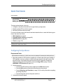
Configuring the SyncServer
Recommended Tasks
GPS antennas not rated for 12 VDC power may be damaged if connected to the SyncServer.
1. Mount the standard L1 GPS antenna (supplied) in a location that offers good visibility of
GPS satellites, such as a rooftop or outdoor antenna mast with wide open views of the
sky and horizon. Avoid obstructions and sources of Radio Frequency Interference.
Observe building codes and regulations. Also see Using GPS (on page 130) and
WARNING: GPS Antenna (on page 121).
2. On the rear panel:
n Connect the GPS antenna cable (supplied) to the GPS Ant connector.
n Connect LAN1 and any of the other network ports to the network.
Consult Warnings and Cautions (on page 121) for safety information regarding
grounding and power.
n Connect the power and turn the power switch on.
3. Using the front panel keypad:
n
997-01520-02 Rev. C.......................................................................... Page 1
Quick Start Guide
Configure LAN1 with a static IP address using the MENU button and 1) LAN1.
n View the LAN1 IP address by pressing the STATUS button repeatedly until the
LAN1 STATUS screen is shown.
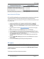
Go to the SyncServer Login page by entering the LAN1 IP address as the URL in Internet
Explorer.
Log in. The user name is "admin". The password is "symmetricom".
Configure the SyncServer using WIZARDS - 1st Setup. Select the following options:
n "Configure Password Recovery" (Ask the IT department for the IP address of the
SMTP server).
n "Send test mail when finished"
n "Set Local Time Zone"
Configure the remaining network ports using NETWORK - Ethernet.
n Assign static IP addresses.
n Protect LAN1 and the other ports from unauthorized IP addresses or address
ranges using the Allowed Access feature.
Configure the NTP clients on your network with the IP address(es) of the SyncServer's
network ports.
n
4.
5.
6.
7.
8.
The SyncServer is providing synchronized time to the network when the SYNC LED (front
panel) is orange or green.
Optional Tasks
In the web interface:
n
n
n
n
n
Connect any other Input References to the rear panel and configure them using the
pages under the REFERENCES section.
Use the NTP – Config page to synchronize the SyncServer with any other NTP servers.
Use WIZARDS - SNMP to set up alarm notification by SNMP.
Use SERVICES - Email to set up alarm notification by email.
When the SyncServer is completely configured, use WIZARDS - Backup to save a backup
file of the configuration to a safe location. Write the location of the backup file on this
printed document and store it in a location that is easy to find.
Page 2 ..........................................................................997-01520-02 Rev. C
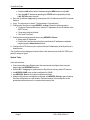
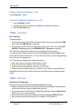
Status LEDs
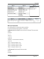
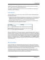
Status LEDs
The four tricolor LEDs provide the following status information:
Red
Sync
Orange
SyncServer is
SyncServer is synnot synchronized chronized to a remote
to a
NTP server.
NTP Stratum 2-15.
reference.
Green
Dark
SyncServer is synchronized to Power off.
an Input Reference or the
modem.
NTP Stratum 1.
NTP Stratum 16.
Network Link failure on the Link failure on the LAN2, All configured ports operational. Power off.
LAN1.
LAN3, or LANGBE.
>7000
NTP
pack> 5000 packets per
NTP activity within the last
No NTP
NTP
ets per second. second.
activity in
second.
the last
Alarm
Major Alarm.
Minor Alarm.
No Current/Enabled Alarms.
second.
Power off.
Also see Stratum (on page 194).
Halting the SyncServer
Symmetricom recommends shutting the operating system down before removing the power.
Using the keypad/display interface:
1.
2.
3.
4.
5.
Press the MENU button.
Select 3) Sys Control.
Select 2) Shutdown.
Press the ENTER button.
When the display shows "System Stopped - OK to Turn Power Off Now!" turn the power
off.
Or, using the web interface:
1. Go to the SERVICES - Startup page.
2. Select Halt and click the APPLY button.
3. Wait approximately 30 seconds before removing power.
997-01520-02 Rev. C.......................................................................... Page 3
Product Overview
The SyncServer Network Time Server offers the following protocols for synchronizing equipment over a network:
n
n
n
n
n
n
NTP
PTP Grand Master (option)
SNTP
Time (TCP and UDP versions)
Daytime (TCP and UDP versions)
Sysplex Output (dedicated port)
These protocols are capable of synchronizing computers, servers, and networking equipment on an enterprise-scale network to within milliseconds of official UTC time. This degree
of synchronization is desirable for precise time-stamping of events and data correlation.
Key Features
n
n
n
n
n
n
n
n
n
n
n
n
n
n
n
n
n
n
Ultra High-Bandwidth NTP Time Server
Stratum 1 Operation via GPS Satellites
Gigabit Ethernet port plus 3 additional Independent 10BASE-T/100BASE-TX Ports
Internal Dial-up Modem for Time Reference Redundancy
Independent Time References: GPS, Timecodes, 1PPS, 10MHz
Versatile Timing Outputs: IRIG A/B/E/G/NASA36/XR3/2137 AM or DCLS, 1PPS,
10MHz, Sysplex
Stratum 2 Operation via NTP Servers
RADIUS, NTPv4 Autokey, MD5 Authentication
Secure Web-Based Management
SSH, SSL, SCP, SNMP, Custom MIB, HTTPS, Telnet, and More
IPv6 and IPv4 Compatible
Nanosecond Time Accuracy to UTC
Alarm Relays
Rubidium & OCXO Oscillator Upgrades
Upgrade to Radio Broadcast Time Sync
Optional T1/E1 Input/Output
IEEE 1588 / PTP Grandmaster Option
Time Interval Measurement Option
Key Benefits
n
n
n
n
n
n
Synchronize Hundreds of Thousands of Client, Server & Workstation Clocks
Very Reliable and Secure Source of Time for Your Network
Multiple NTP Ports for Easy Network Configuration and Adaptation
Extremely Accurate Time Source for Network Synchronization
Enhanced Network & Security Features
User Prioritized Reference Selection between, GPS, Timecode, 1PPS and 10MHz
997-01520-02 Rev. C.......................................................................... Page 5
Product Overview
n
n
Access Multiple Time Sources for Reliable and Secure Time
Intuitive Web Interface for Easy Control & Maintenance
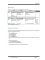
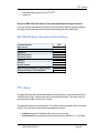
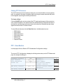
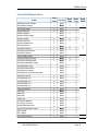
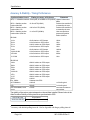
Comparison by Model
SyncServer Model Comparison
Time
Protocols
Feature
NTP Server (v2, v3, v4)
Y
NTP Broadcast Server/Client
NTP Peering/Client
NTP Multicast Server/Client
IEEE 1588 PTP Grandmaster (optional)
SNTP, Time, Daytime
NTP performance, requests/second
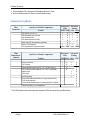
Time
References
(inputs)
Enterprise Advanced
Class
Timing
S200 S300 S250 S350
SyncServer Model Comparison
Feature
Y
Y
Y
Y
Y
Y
Y
Y
Y
Y
Y
Y
Y
Y
Y
Y
Y
Y
Y
Y
Y
3200 7000 3200 7000
Enterprise Advanced
Class
Timing
S200 S300 S250 S350
GPS (12 channel)
Y
NTP Peering
Y
Dial-up internal modem (ACTS, JJY, ITU-R TF583.4)
Low Frequency Radio (WWVB, JJY, DCF77) (optional)
Y
Y
Y
Y
Y*
Y
10MHz input
Y
1PPS input
Y
IRIG B AM Input
Y
IRIG A/B/E/G/NASA36/XR2/2137 inputs (AM & DCLS)
T1/E1 input (optional)
Time Interval Measurement & Charting (S350 PTP Option)
Reference priority, user configurable
* The S250i model uses a timecode input instead of GPS as its primary Input Reference.
Page 6 ..........................................................................997-01520-02 Rev. C
Y
Y
Y
Y
Y
Y
Y
Y
Y
Y
Y
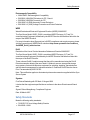
Comparison by Model
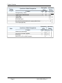
Network
Security
Protocols
SyncServer Model Comparison
Feature
HTTP/HTTPS/SSL
Telnet (w/disable fcn.)
SNMP V1, V2c, V3 with Custom MIB II
DHCP (w/disable can.)
SSH/SCP (w/disable fcn.)
IPv6 and IPv4/IPv6
MD5 for NTP
NTP v4 Autokey (Server and Client)
RADIUS Authenticated login
1000Base-T equipped port (Gigabit)
Total number of Ethernet ports
SyncServer Model Comparison
User Interface
Feature
Enterprise Advanced
Class
Timing
S200 S300 S250 S350
Y
Y
Y
Y
Y
Y
Y
3
Y
Vacuum fluorescent display/multi-line
Y
Numeric keypad
Y
LED’s: Sync, Network, Alarm, NTP
Y
USB
Y
RS-232 Console Port
Y
Alarm relays
Keypad lockout
Oscillator
Feature
Y
Y
Y
Y
Y
Y
Y
Y
Y
Y
4
Y
Y
Y
Y
Y
Y
3
Enterprise Advanced
Class
Timing
S200 S300 S250 S350
Web Interface
SyncServer Model Comparison
Y
Y
Y
Y
Y
Y
Y
Y
Y
Y
Y
4
Y
Y
Y
Y
Y
Y
Y
Y
Y
Y
Y
Y
Y
Y
Y
Y
Y
Y
Y
Y
Y
Y
Enterprise Advanced
Class
Timing
S200 S300 S250 S350
OCXO upgrade
Y
Rubidium upgrade
Y
Y
Y
997-01520-02 Rev. C.......................................................................... Page 7
Y
Y
Y
Y
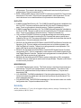
Product Overview
Timing
Outputs
SyncServer Model Comparison
Feature
Enterprise Advanced
Class
Timing
S200 S300 S250 S350
Timing accuracy +/-50 ns
Y
Sysplex output (dedicated port)
Y
Y
Y
Y
Y
Y
Y
Y
Y
Y
Y
Y
1PPS output
Y
10MHz output
Y
IRIG B AM output
Y
IRIG A/B/E/G/NASA36/XR2/2137 outputs (AM & DCLS)
T1/E1 output (optional)
Misc.
SyncServer Model Comparison
Feature
Enterprise Advanced
Class
Timing
S200 S300 S250 S350
General server status logs
Y
Autocheck for firmware upgrades
Y
Email alerts
Y
Serve NTP in UTC or GPS Timescale
Y
Y
Y
Y
Page 8 ..........................................................................997-01520-02 Rev. C
Y
Y
Y
Y
Y
Y
Y
Web Interface
This section provides a topic for each page in the web interface, with an explanation of each
field, notes, and links to related topics.
This section contains
Login
Properties of User Names and Passwords
STATUS - General
STATUS - Network
STATUS - Timing
STATUS - GPS
WARNING: GPS Position and Altitude
STATUS - NTP
NTP Daemon Status
STATUS - PTP
PTP Daemon Status
STATUS - Alarms
NETWORK - Ethernet
NETWORK - SNMP
NETWORK - SNMP Traps
NETWORK - Ping
NTP - Sysinfo
NTP Daemon Status
NTP - Assoc
NTP - Config
NTP - MD5 Keys
NTP - Autokey
NTP - Autokey Client
NTP - Prefs
PTP Option and Time Interval Test
Time Interval Test
PTP and NTP Performance
PTP Management Messages
How to Activate the PTP Option
PTP - Master
IEEE 1588-2008 Annex J Recommended Default Settings
PTP - Slaves
PTP - Performance
Charting PTP Performance
PTP - Save-Restore
To Save Configuration Settings to a File
To Restore Configuration Settings from a File
TIMING - Time Zone
TIMING - HW Clock
TIMING - Holdover
997-01520-02 Rev. C.......................................................................... Page 9
11
11
12
13
14
14
16
16
16
19
19
20
20
23
24
25
25
25
28
30
33
34
35
36
37
38
38
40
41
41
45
45
46
47
47
48
48
48
48
50
Web Interface
TIMING - Sysplex
TIMING -Time Interval
REFERENCES - GPS
GPS Position and Operating Mode
REFERENCES - Timecode
REFERENCES - Modem
RESTART button
REFERENCES - LF Radio
REFERENCES - T1/E1
SYSTEM - General
SYSTEM - Upgrade
SYSTEM - Factory Reset
Factory Default Settings
SYSTEM - Options
ADMIN - Web
ADMIN - Users
ADMIN - Alarms
Alarm Descriptions
Factory Default Settings for Alarms
ADMIN - Logs Config
ADMIN - Relays
ADMIN - RADIUS
SERVICES - Startup
SERVICES - HTTP
SERVICES - SSH
SERVICES - Email
LOGS
WIZARDS - 1st Setup
WIZARDS - NTP
WIZARDS - SNMP
WIZARDS - Backup
WIZARDS - Restore
WIZARDS - Upgrade
Page 10 ..........................................................................997-01520-02 Rev. C
51
54
57
57
58
59
62
62
63
63
64
64
65
69
69
71
72
73
77
78
80
80
81
82
83
84
84
85
86
86
86
86
87
Login
Login
Use the Login page to:
n
n
n
Log in to the Sync Server's web interface.
Recover lost passwords.
View system status.
The Login page includes the following elements:
n
n
n
n
Username: Enter the username here. (Factory default: "admin")
Password: Enter the corresponding password here. (Factory default: "symmetricom")
Secure: Opens an encrypted web session (HTTPS, port 443). For this feature to be available, the user must enable it by using the SERVICES - HTTP page.
Recover Password: Prompts the user to answer a password recovery question. If the user
answers correctly, the Sync Server resets the password to a random string and emails it
to the user's email address. For this feature to be available, the user must enable it using
the ADMIN - Users or WIZARDS - 1st Setup pages.
Use the ADMIN - Web (on page 69) page to configure the status information on the Login page.
Also see Logging in to the Web Interface (on page 139) and Recovering a Password
(on page 155).
PropertiesofUserNamesandPasswords
Usernames
Quantity & Length
There is an upper limit of 32 individual users, each username has a maximum of 32 characters in length.
Character set (Charset)
Each username is limited to the following printable ASCII characters:
n
n
n
n
n
n
n
Upper case letters {A-Z}
Lower case letters {a-z}
Numbers {0-9}
Period {.}
Dash {-}
Underscore {_}
Plus {+}
Usernames may NOT contain any of the following:
n
Standard ASCII keyboard characters not described above, i.e. ! @ # $ % ^ & * ( ) = { } [ ] |
\;:'"<>?,/
997-01520-02 Rev. C.......................................................................... Page 11
Web Interface
n
n
n
n
n
Grave accent {`}
Tilde {~}
Whitespace characters (space, tab, linefeed, carriage-return, formfeed, vertical-tab etc.)
Non-ASCII characters
Non-printable characters
Passwords
Length
The password can have a maximum of 64 characters in length.
Character set (Charset)
Passwords must contain, at minimum, either a mix of upper and lowercase letters, or a mix of
letters and numbers.
Passwords are limited to the following printable ASCII characters:
n
n
n
n
n
Upper case letters {A-Z}
Lower case letters {a-z}
Numbers {0-9}
Tilde {~}
Most standard ASCII keyboard symbols, i.e. ! @ # $ % ^ & * ( ) _ - = { } [ ] | : ; " < > , . ? /
Passwords may NOT be all-lowercase, all-uppercase, all-numeric, or match the username.
They additionally may NOT contain any of the following:
n
n
n
n
n
n
n
Single-quote / apostrophe {'}
Grave accent {`}
Plus {+}
Backslash {\}
Whitespace characters (space, tab, linefeed, carriage-return, formfeed, vertical-tab etc.)
Non-ASCII characters
Non-printable characters
STATUS - General
Overall System Information
n
n
n
n
Hostname: The network hostname of the SyncServer, which can be configured on the
SYSTEM - General web page.
Model: The model number of the SyncServer.
Serial Number: The unique serial number of the SyncServer.
Local Time: The local time, determined by the time zone setting on the TIMING - Time Zone
web page.
Page 12 ..........................................................................997-01520-02 Rev. C
STATUS - Network
n
n
n
n
n
n
n
n
n
n
n
Release Version: The system release version.
Software Version: The software version.
Hardware Clock Version: The version of the software on the Hardware Clock.
Up Time: The time elapsed since the operating system started.
Load Average: A figure of merit for the operating system “load” for the previous 1, 5, and
15 minutes (left to right).
Memory Used (Mbyte): The amount of memory occupied by the system.
Memory Free (Mbyte): The amount of free memory remaining.
Flash: The type of compact flash card installed.
CPU Vendor: The CPU vendor/manufacturer.
Model: The CPU model.
Number: The CPU number.
STATUS - Network
Network Status for each of the SyncServer's network ports:
n
n
n
The name of the Port.
The following Address information for each network port:
n mac: The MAC Address.
n v4: The IPv4 Address, if used.
n v6 link: The IPv6 Address, if used.
The State of the physical network port device (not of the connection). An "Up Arrow"
means it is "running". A "Down Arrow" means it is "not running".
Management Port DNS Servers: Both user-entered and DHCP-assigned DNS Server
addresses that are available from the LAN1 port.
The SyncServer requires at least one valid DNS server to resolve domain names, which
may be used in NTP associations, and SMTP gateways (email). Without a DNS server, any
function that uses a DNS name instead of an IP address may be affected. These can include
NTP, password recovery, and email notification of alarms.
997-01520-02 Rev. C.......................................................................... Page 13
Web Interface
STATUS - Timing
Hardware Clock Status
Current Sync Source: The Input Reference currently used by the Hardware Clock. Consult the
TIMING - HW Clock topic for more information.
Hardware Clock Time: The time according to the Hardware Clock.
Hardware Clock Status: "Locked" means the Hardware Clock is synchronized to one of its references, or to the internal oscillator in "Holdover". "Unlocked" means the Hardware Clock
doesn't have an Input Reference and the Holdover period has expired. Also see TIMING HW Clock (on page 48) and TIMING - Holdover (on page 50).
Oscillator Type: The type of the oscillator installed in the Hardware Clock for operation and
holdover.
For each of the following Input Status lines, "Locked" means that the reference is valid and
can be selected by the Hardware Clock. "Unlocked" means the reference is not valid, and is
therefore not available for use by the Hardware Clock. Also see TIMING - HW Clock (on
page 48) to arrange the priority of the Input References.
Some of these references are options or are only available in specific SyncServer models.
(Consult Product Overview (on page 5) for more information about features and models):
n
n
n
n
n
n
GPS Input Status
Timecode Input Status
1PPS Input Status
10MHz Input Status
LFR Input Status
T1/E1 Input Status
Leap Warning: The state of the Leap Indicator (on page 189) as reported by the current input
reference.
STATUS - GPS
GPS Receiver Operation
This page displays the status of the GPS Receiver.
Receiver Description: "GPS" indicates the presence of a 12-channel GPS receiver.
Receiver Status:
n
n
n
n
n
Receiver Down: The Hardware Clock can't communicate with the receiver.
Unknown Mode: An undefined mode of the GPS receiver.
Acquiring Signal: The receiver is attempting to track a GPS signal.
Bad Geometry: The geometry of the tracked satellites is unsatisfactory for a position solution.
Propagate Mode: A position estimation mode used in highly dynamic environments.
Page 14 ..........................................................................997-01520-02 Rev. C
STATUS - GPS
n
n
n
n
2d Solution: The receiver is able to perform position fixes for latitude and longitude but
does not have enough satellites for altitude.
3d Solution: The receiver is now able to perform position fixes for latitude, longitude and
altitude.
Position Hold: Position fixes are no longer attempted, and the surveyed or user-entered
position is used.
Time Valid: The receiver has valid timing information from GPS satellites (including GPSUTC Offset and Leap Indicator). If the GPS receiver and antenna are set up correctly, the
receiver status should eventually reach and remain in this state.
Mode:
Survey: The receiver is surveying and averaging its position. When it has finished surveying, the receiver switches to Position Hold mode. Survey mode and Position Hold
mode are appropriate for static applications, such as a typical server room environment.
This is the default mode when the SyncServer starts.
n Dynamic: The GPS receiver surveys continuously to determine its position and doesn't
switch to another mode. This mode must be initiated by a user, and is appropriate for
mobile applications such as ships, land vehicles, and aircraft. The degree of accuracy this
mode offers is fine for NTP time over networks, but is less than optimal for the timing outputs available on some SyncServer models.
n Position Hold: The GPS receiver has completed Survey mode and switched to this
mode, or the user has manually entered a position and "forced" it into this mode. The
accuracy and stability of the SyncServer's timing outputs are optimal when the receiver
has its exact position and is in this mode.
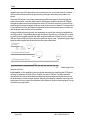
Antenna Cable Delay (nS):
n
The user-configured value (on the REFERENCES - GPS page) to compensate for GPS signal
propagation from the antenna along the length of the cable to the receiver.
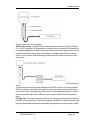
Antenna Status:
The GPS receiver supplies power to the GPS antenna through the antenna cable. It also
monitors the current to that circuit to detect open or short circuits.
n
n
n
Good: The current to the GPS antenna and cable is normal.
Open: The current is too low. The GPS antenna or cable is probably disconnected or
broken. Some splitters may cause this condition as well.
Short: The current is too high. The GPS antenna or cable probably has a short circuit.
Position: The latitude and longitude of the GPS antenna in degrees, minutes, and fractional
seconds. Referenced to WGS-84.
Altitude: The altitude of the antenna in meters. Referenced to WGS-84.
Satellites: The list of GPS satellites visible to the receiver:
n
n
n
Sat Number: The GPS satellite's Satellite Vehicle (SV) number, a unique identification
number
Signal: The relative strength of the GPS signal (dBW = decibels relative to 1 Watt).
Status: "Current" means that the receiver is using the GPS signal in its timing solution.
"Tracked" means the receiver is tracking the signal, but isn't using it in the timing solution.
997-01520-02 Rev. C.......................................................................... Page 15
Web Interface
WARNING:GPSPositionandAltitude
GPS position and altitude are for timing purposes only. They are not intended for navigation
or other critical applications.
AVERTISSEMENT : La position et l'altitude de GPS sont seulement pour la synchronization. Elles ne sont pas prévues pour la navigation ou d'autres situations critiques (situations de la vie-ou-mort).
STATUS - NTP
NTPDaemonStatus
This page displays the status of the NTP daemon. Many of the fields below are based on the
NTP Packet (on page 190). Also see http://www.ntp.org.
system peer: The IP address of the clock source. The source is selected by the NTP daemon that is most likely to provide the best timing information based on: stratum, distance, dispersion and confidence interval. The system peer identified as "SYMM_TE(0)" is the local
SyncServer Hardware Clock. Also see Hardware Clock (on page 188).
system peer mode: The relationship of the SyncServer to a system peer, usually a "client".
Depending the configuration, the mode can be:
n
n
n
Client: A host operating in this mode sends periodic messages regardless of the reachability state or stratum of its peer. By operating in this mode the host, usually a LAN workstation, announces its willingness to be synchronized by, but not to synchronize the peer.
Symmetric Active: A host operating in this mode sends periodic messages regardless
of the reachability state or stratum of its peer. By operating in this mode the host
announces its willingness to synchronize and be synchronized by the peer.
Symmetric Passive: This type of association is ordinarily created upon arrival of a message from a peer operating in the symmetric active mode and persists only as long as the
peer is reachable and operating at a stratum level less than or equal to the host; otherwise, the association is dissolved. However, the association will always persist until at
least one message has been sent in reply. By operating in this mode the host announces
its willingness to synchronize and be synchronized by the peer.
A host operating in client mode (a workstation, for example) occasionally sends an NTP message to a host operating in server mode (the SyncServer), perhaps right after rebooting and
at periodic intervals thereafter. The server responds by simply interchanging addresses and
ports, filling in the required time information and returning the message to the client. Servers
need retain no state information between client requests, while clients are free to manage
the intervals between sending NTP messages to suit local conditions.
In the symmetric modes, the client/server distinction (almost) disappears. Symmetric passive
mode is intended for use by time servers operating near the root nodes (lowest stratum) of
the synchronization subnet and with a relatively large number of peers on an intermittent
basis. In this mode the identity of the peer need not be known in advance, since the association with its state variables is created only when an NTP message arrives. Furthermore,
Page 16 ..........................................................................997-01520-02 Rev. C
STATUS - NTP
the state storage can be reused when the peer becomes unreachable or is operating at a
higher stratum level and thus ineligible as a synchronization source.
Symmetric active mode is intended for use by time servers operating near the end nodes
(highest stratum) of the synchronization subnet. Reliable time service can usually be maintained with two peers at the next lower stratum level and one peer at the same stratum level,
so the rate of ongoing polls is usually not significant, even when connectivity is lost and error
messages are being returned for every poll.
leap indicator (LI):
The Leap Indicator (LI) is a two-bit binary number in the NTP packet header that provides
the following information:
Advance warning that a leap second adjustment will be made to the UTC timescale at the
end of the current day. Leap seconds are events mandated by the world time authority
(BIPM) in order to synchronize the UTC time scale with the earth's rotation.
Whether the NTP daemon is synchronized to a timing reference. The settings on the
NTP - Prefs (on page 36) page affect LI behavior.
n
n
LI Value
Meaning
00
01
0
1
No warning.
Leap second insertion: Last minute of the day has 61 seconds.
10
11
2
3
Leap second deletion: Last minute of the day has 59 seconds.
Alarm condition (Not synchronized)
When the SyncServer or NTP daemon is started or restarted, the leap indicator is set to "11",
the alarm condition. This alarm condition makes it possible for NTP clients to recognize that
an NTP server (the SyncServer) is present, but that it has yet to validate its time from its time
sources. Once the SyncServer finds a valid source of time and sets its clock, it sets the leap
indicator to an appropriate value. The NTP Leap Change Alarm on the ADMIN - Alarms
page can be configured to generate an alarm and send notifications each time the leap indicator changes state.
stratum:
This is an eight-bit integer that indicates the position of an NTP node within an NTP timing
hierarchy. It is calculated by adding 1 to the stratum of the NTP system peer.
For the SyncServer, the stratum values are defined as follows:
Stratum
0
1
2-15
16-255
Definition
Hardware Clock when locked.
Primary server
Secondary server
Unsynchronized, unreachable.
For example, the SyncServer is:
997-01520-02 Rev. C.......................................................................... Page 17
Web Interface
n
n
n
stratum 1 when the Hardware Clock (stratum 0) is synchronized to an input reference, in
holdover mode, or in freerun mode.
stratum 2 through 15 when it is synchronized to a remote NTP server.
stratum 16 when it is unsynchronized, indicating that it is searching for a valid source of
timing information.
The settings on the NTP - Prefs (on page 36) page affect stratum behavior.
precision: This is a signed integer indicating the precision of the selected peer clock, in seconds to the nearest power of two. A typical value is -18 for a Hardware Clock where the
uppermost 18 bits of the time stamp fractional component have value, indicating a precision
in the microsecond range.
root distance (also root delay): This is a measure of the total round trip delay to the root of
the synchronization tree. A typical value for a SyncServer operating at stratum 1 would be 0
since the SyncServer is a root of the synchronization tree For other stratum levels, an appropriate value is displayed. Depending on clock skew and dispersion, this value could be positive or negative.
root dispersion: This is a signed fixed-point number indicating the maximum error relative
to the primary reference source at the root of the synchronization subnet, in seconds. Only
positive values greater than zero are possible.
reference ID: This is a four-byte field used to identify the reference clock source. At initialization, while the stratum is 16, this field shows the progression of the NTP clock PLL. The
field will start with a value of INIT (may be displayed as 73.78.73.84, the ASCII decimal
values). Once a peer has been selected, the clock may be stepped, in which case the reference ID field will change to STEP (or 83.84.69.80). Once the PLL is locked, the stratum
will be updated and the reference ID will identify the selected peer. In the case of a SyncServer operating at stratum 1, the reference ID will display the source for the local timing reference (e.g., GPS, IRIG, FREE). In the case where the selected peer is another NTP
server, the reference ID will display the IP address of the server or a hash unique to the association between the SyncServer and the remote server.
reference time (also reference timestamp): The time when the SyncServer last received
an update from the selected peer. Represented using time stamp format in local time. If the
local clock has never been synchronized, the value is zero. A time stamp of zero corresponds
to a local time of Thu, Feb 7 2036 6:28:16.000. This value is typically updated every 16 seconds for a locally attached hardware reference (e.g., GPS, IRIG) and in an interval of 641024 seconds for a readily accessible remote NTP server.
system flags: These flags define the configured behavior NTP daemon running on the
SyncServer. The definition of the variables is provided.
n
n
n
n
n
kernel: The NTP daemon is enabled for the precision-time kernel support for the ntp_
adjtime() system call.
monitor: The NTP daemon is enabled its monitoring facility.
ntp: Enables the server to adjust its local clock by means of NTP.
stats: The NTP daemon is enabled itsstatistics facility.
auth: The NTP daemon is enabled itsauthentication facility.
Page 18 ..........................................................................997-01520-02 Rev. C
STATUS - PTP
jitter: Jitter (also called timing jitter) refers to short-term variations in frequency with components greater than 10 Hz.
stability: Stability refers to how well the SyncServer can maintain a constant frequency over
time. It is usually affected by aging, environment changes, etc. The value is expressed units
of parts per million (ppm).
broadcastdelay: The broadcast and multicast modes require a special calibration to determine the network delay between the local and remote servers. Typically, this is done automatically by the initial protocol exchanges between the client and server. This is the
broadcast or multicast delay reported by the NTP daemon. The value is always set to 0.004
seconds on the SyncServer.
authdelay: When NTP authentication is enabled and performed on outgoing NTP packets,
this adds a trivial amount of fixed delay that can be removed based on the authdelay value.
This value is always set to zero on the SyncServer.
STATUS - PTP
This page will only appear if the IEEE-1588 2008 PTP option has been activated.
See "How to Activate the PTP Option" on page 41
From this page, the status of a list of PTP system parameters of the PTP Daemon can be
viewed.
See "PTP - Master" on page 41
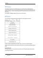
PTPDaemonStatus
Field
Clock ID
PTP Slaves Tracked
PTP Version
Clock Class
Clock Accuracy
Time Source
Current UTC Offset
UTC Valid
Leap 59
Leap 61
Time Traceable
Frequency Traceable
Transport Protocol
Example of Field Value
00:a0:69:ff:fe:01:6e:8d
"0"
"2"
"6" (Synchronized)
"21" (Within 100 ns)
"20" (GPS)
"34 sec"
True or False
True or False
True or False
True or False
True or False
The choices for the Transport Protocol are:
l
l
IPv4/UDP – this is Default
802.3
997-01520-02 Rev. C.......................................................................... Page 19
Web Interface
Field
Sync Interval
Delay Mechanism
ITT
E2E Delay Interval
P2P Delay Interval
Priority 1
Priority 2
Domain Number
Announce Transmit Interval
Announce Timeout Multiplier
Example of Field Value
"1 pkt/1 sec"
"E2E"
"1"
"1 pkt/1 sec"
"1 pkt/1 sec"
"128"
"128"
"0"
"2 sec"
"3"
STATUS - Alarms
Current Major or Minor Alarms
Alarms with Severity set to:
n
n
n
Major are displayed in red text.
Minor are displayed in orange text.
Notify are not displayed.
Alarms can be configured using the ADMIN - Alarms page.
For each listing:
Time: The local date and time at which the alarm was raised.
Severity: The severity of the alarm event (Major/Minor).
Name: The name of the alarm, from the list of alarms on the ADMIN - Alarms page.
NETWORK - Ethernet
Use this page to get status and configure Ethernet LAN port network settings, including DNS
servers.
Ethernet Port Configuration
Edit the network port configuration and view network port status.
EDIT: Clicking this button opens a dialog box for configuring the network port.
Pending Changes: A check mark indicates that settings have changed, reminding the user
to click the APPLY button.
Port: The name of the network port.
IP Address: The port's MAC, IPv4, and/or IPv6 network addresses.
Usage: These icons summarize information about the port:
Page 20 ..........................................................................997-01520-02 Rev. C
NETWORK - Ethernet
n
n
n
n
n
n
n
(Checkmark): The user has changed the configuration, but hasn't clicked the APPLY
button at the bottom of the page yet.
(Management Port): This network port is configured as the management port (web
interface, SNMP, email, DNS).
(Up Arrow): The physical network port is enabled and functioning (does not indicate a
valid physical connection or configuration).
(DHCP): The network configuration is automatic via DHCP
(Question Mark): Status unknown - usually when there are pending changes.
(Number "6"): Uses IPv6
(Letter "B"): Configured for bonding with another port in a redundant pair.
DNS Servers
The DNS Server fields display the IP addresses of Domain Name Service (DNS) servers.
The SyncServer requires a valid DNS server address to resolve domain names, such as the
"ntp1.symmetricom.com" NTP association. If a DNS server isn't provided, NTP associations
(NTP - Config) and the SMTP Gateway (SERVICES - Email) must be specified using an
IP address. DNS messages are only communicated through LAN1 port. The specified DNS
servers must be reachable from the LAN1 port.
n
n
Management Port User DNS Servers: Manually enter one or more DNS Server IP
addresses here, if not supplied by DHCP.
Management Port DHCP DNS Servers (Read Only): If LAN1 has DHCP enabled,
and DHCP is configured to supply DNS server addresses, displays the DNS server IP
addresses supplied by DHCP. These values are not user-editable.
Note: If the SMTP Gateway (which supports Password Recovery and Email Notification of
Alarms) and NTP associations are addressed using domain names, a valid DNS server
address must be supplied to the SyncServer.
Network Port Configuration
To edit the settings for a network port, click the corresponding EDIT button on the NETWORK - Ethernet page. This opens a dialog box titled with the name of the port followed by
"Configuration".
To apply configuration changes, click APPLY buttons on both this configuration window and
later on the NETWORK - Ethernet page.
Connection Mode:
n
n
n
Static: A user must configure the network port manually.
DHCP: A DHCP server will automatically configure the network port when changes are
applied. Not available for IPv6.
Disabled: This disables the network port.
Note: If the Connection Mode is DHCP and the lease expires or the SyncServer reboots, a
DHCP server could assign a new IP address to the SyncServer’s network port. If this occurs
with the LAN1 port, use the STATUS button on the front panel to obtain the new IP address.
Furthermore, if it occurs to a network port servicing NTP requests, NTP clients will no longer
be able to get a response from that port. In that case, the NTP clients would have to use an
997-01520-02 Rev. C.......................................................................... Page 21
Web Interface
alternate NTP source or become unsynchronized. For this reason, Symmetricom recommends using static IP addresses, only using DHCP for convenience during temporary
installations.
IP Version:
n IPv4: The port uses IPv4 exclusively. (Static or DHCP)
n IPv6: The port uses IPv6 exclusively. The user must enter a static IPv6 address.
IP Address: The port's IPv4 address (e.g., "192.168.0.100") or IPv6 address(es) with
scope (e.g., fe80::2a0:6dff:fe00:10).
Mask: The port's IPv4 subnet mask (e.g., "255.255.255.0"). With IPv6, the mask is the
length of the prefix.defined in CIDR format (Classless Inter Domain Routing). Typically, the
IPv6 mask is 64.
Gateway: The port's IPv4 or IPv6 gateway (e.g., "192.168.0.1"). This is an optional configuration parameter.
Management: Reserved for future use.
Redundant: Bonds LAN3 to LAN2 as virtual device with a single network address.
n
n
Active: The Active port handles network traffic. LAN2 is "Active" by default.
Backup: The Backup port handles network traffic if the connection to the Active port fails.
LAN3 is the "Backup" port by default.
If the connection to LAN2 fails, LAN2 becomes backup and LAN3 becomes active. After
repairing the connection, the user can manually reconfigure LAN2 as the Active port:
1. In the "LAN2 Configuration" window, select the "Redundant" checkbox, select "Active",
and then click the APPLY button.
2. On the NETWORK - Ethernet page, click the APPLY button.
To release a redundant bond, deselect the "Redundant" checkbox and apply the changes. If
the bond doesn't release, reboot the SyncServer.
Allowed Access: Restricts the LAN port to access by specified IP addresses or address
ranges. If the user leaves this field blank, the LAN port accepts connections from any IP
address. Allowed Access applies to all forms of network traffic, including NTP and HTTP connections. Reconfiguring the IP address of the LAN port erases the Allowed Access list.
The user can specify address ranges by setting the IP address followed by the mask prefix
length, as described RFC 1518 and RFC 1519 for Classless Interdomain Routing. The
mask prefix length specifies the number of masked bits starting from the left-most position. For example, to allow access from the network represented by 192.168.0.0,
255.255.0.0, the user would enter 192.168.0.0/16. In other words, the first 16 bits of the
address, 192.168, are masked bits representing the network address The remaining bits are
host address which is set to 0.
Note: When configuring Allowed Access, take care to avoid blocking DNS, HTTP, NTP,
RADIUS, SMTP, SNMP, and SSH traffic.
Speed/Duplex: Sets the network port speed automatically (Auto), to 10 or 100. Sets the
transmission to Full or Half duplex. User must exercise caution when changing speed and
duplex settings on any of the SyncServer ports. Speed and duplex settings on a network port
Page 22 ..........................................................................997-01520-02 Rev. C
NETWORK - SNMP
are negotiated with its network link partner. Depending on the settings of the port’s link partner, the requested settings may not be actually taken. Sometimes the network link between
the port and its link partner may be lost due to changing of the speed and duplex settings.
Symmetricom recommends using the Auto setting.
Side Effects
Applying changes to the Ethernet port configuration restarts the NTP and xinetd daemons
(services). During that time:
n
n
The NTP daemon, NTP stratum, web interface are temporarily unavailable.
The Status LEDs, NTP stratum, and Alarms change states.
NETWORK - SNMP
This page provides configuration of basic SNMP settings and the creation of SNMPv3 users.
Basic Configuration
Establish the identity and community membership of the device.
sysLocation: Identify the location of the SyncServer (e.g. Server Room A, Company
Division B, etc). Used by network management consoles.
sysName: Provide the SyncServer with a unique name. (This is distinct and separate from
"hostname" on the SYSTEM - General and STATUS - General pages.) Used by network
management consoles.
sysContact: The name of the individual responsible for the SyncServer. Used by network
management consoles.
Read Community: The SNMP read community string. The string must be provided for
SNMP v1/v2c GETS/WALKS to gain access.
Write Community: The SNMP write community string.
Note: At this time, the SyncServer does not support any writable SNMP variables.
V3 Users
SNMP user names are separate and distinct from the access control list usernames used to
log in to the SyncServer's user interfaces. SNMP user names are used by the network management software.
This is the list of SNMP v3 users. To delete a user, select the checkbox for a user name and
click the DELETE button. When prompted, enter the passphrase specified when the user
was created. The SNMP admin user cannot be deleted.
(Using SNMP v3 requires an SNMP v3 user on the recipient systems' SNMP v3-capable
agent/client)
User Name: Name of v3 User.
Mode: Currently only rouser (read-only user) mode is supported.
Level: Shows the Min Priv level of the user (see Min Priv, below):
997-01520-02 Rev. C.......................................................................... Page 23
Web Interface
n
n
n
n
auth: Authentication
noauth: No Authentication
priv: Auth and Privacy
blank: default level for admin
Add v3 User
To create an SNMPv3 user, complete the form and click the SAVE button.
Name: Alphanumeric user name, with no spaces or special characters.
Auth Phrase: Create a unique authentication passphrase for the user. It must be at least
eight characters long.
Auth Crypt: The authentication type, MD5 or SHA1. It uses the Auth Phrase as its key
when calculating the message hash.
Priv Phrase: Creates a unique encryption passphrase for messages exchanged between
the network management software and the SyncServer. It must be at least eight characters
long.
Min Priv: Establishes the minimum authentication level required for the user. One of the following must be selected:
n
n
Authentication (Auth): Auth Phrase is always required
Auth and Privacy (Priv): Auth and Priv Phrase are always required
NETWORK - SNMP Traps
Use this page to configure, add, or delete SNMP trap recipients. The page is divided into two
sections. The first section displays the current recipients. The second section provides a form
for adding recipients or modifying existing recipients. The first section only displays basic
information for each recipient.
Trap Recipients
Destination: The IP address to which traps are to be sent.
Ver: The SNMP version (v1, v2c or v3).
(Send as Inform): If trap is to be sent as inform, ‘inform’ is written, otherwise is blank.
User/Community: For SNMPv1/v2c traps, an optional community. For SNMPv3 traps, a
required SNMP v3 user on the recipient system. (Using SNMP v3 requires an SNMP v3
user on the recipient systems' SNMP v3-capable agent/client)
Add/Edit Trap Recipient
IP Address: The IP address to which traps are to be sent.
The SNMP version: v1, v2c, or v3.
User/Community: For SNMPv1/v2c traps, an optional community. For SNMPv3 traps, a
required SNMP v3 user on the recipient system.
Send as Inform: Sends an INFORM-PDU, otherwise a TRAP-PDU or TRAP2-PDU is sent.
Auth Phrase: For SNMPv3 traps, an optional Auth Phrase.
Page 24 ..........................................................................997-01520-02 Rev. C
NETWORK - Ping
The hash algorithm used for the Auth Phrase: MD5 or SHA1.
Priv Phrase: For SNMPv3 traps, an optional Priv Phrase.
To edit a trap recipient, select the checkbox of a specific recipient and click the EDIT button.
Edit the values displayed in Add/Edit Trap Recipient and click the SAVE button. Similarly,
use the DELETE button to remove trap recipients from the list.
NETWORK - Ping
Network Ping Test
Use this page to PING a network node from one of the SyncServer's network ports. This feature can be used to test and troubleshoot network connectivity issues.
To use PING:
1. Select the network port from which to send the PING packets.
2. For IPv6 networks, select Ping 6.
3. Enter the IP address of the host and click the APPLY button. Ping Output displays the results
five seconds after clicking apply.
Note: The approximate command line equivalent is "ping -c 5 -w 5", where "-c 5" means
"send five request packets to the requested destination" and "-w 5" means "timeout after 5
seconds if no responses". The network port that sends the ping request also receives the
responses.
NTP - Sysinfo
NTPDaemonStatus
This page displays the status of the NTP daemon. Many of the fields below are based on the
NTP Packet (on page 190). Also see http://www.ntp.org.
system peer: The IP address of the clock source. The source is selected by the NTP daemon that is most likely to provide the best timing information based on: stratum, distance, dispersion and confidence interval. The system peer identified as "SYMM_TE(0)" is the local
SyncServer Hardware Clock. Also see Hardware Clock (on page 188).
system peer mode: The relationship of the SyncServer to a system peer, usually a "client".
Depending the configuration, the mode can be:
n
n
n
Client: A host operating in this mode sends periodic messages regardless of the reachability state or stratum of its peer. By operating in this mode the host, usually a LAN workstation, announces its willingness to be synchronized by, but not to synchronize the peer.
Symmetric Active: A host operating in this mode sends periodic messages regardless
of the reachability state or stratum of its peer. By operating in this mode the host
announces its willingness to synchronize and be synchronized by the peer.
Symmetric Passive: This type of association is ordinarily created upon arrival of a message from a peer operating in the symmetric active mode and persists only as long as the
peer is reachable and operating at a stratum level less than or equal to the host;
997-01520-02 Rev. C.......................................................................... Page 25
Web Interface
otherwise, the association is dissolved. However, the association will always persist until
at least one message has been sent in reply. By operating in this mode the host
announces its willingness to synchronize and be synchronized by the peer.
A host operating in client mode (a workstation, for example) occasionally sends an NTP message to a host operating in server mode (the SyncServer), perhaps right after rebooting and
at periodic intervals thereafter. The server responds by simply interchanging addresses and
ports, filling in the required time information and returning the message to the client. Servers
need retain no state information between client requests, while clients are free to manage
the intervals between sending NTP messages to suit local conditions.
In the symmetric modes, the client/server distinction (almost) disappears. Symmetric passive
mode is intended for use by time servers operating near the root nodes (lowest stratum) of
the synchronization subnet and with a relatively large number of peers on an intermittent
basis. In this mode the identity of the peer need not be known in advance, since the association with its state variables is created only when an NTP message arrives. Furthermore,
the state storage can be reused when the peer becomes unreachable or is operating at a
higher stratum level and thus ineligible as a synchronization source.
Symmetric active mode is intended for use by time servers operating near the end nodes
(highest stratum) of the synchronization subnet. Reliable time service can usually be maintained with two peers at the next lower stratum level and one peer at the same stratum level,
so the rate of ongoing polls is usually not significant, even when connectivity is lost and error
messages are being returned for every poll.
leap indicator (LI):
The Leap Indicator (LI) is a two-bit binary number in the NTP packet header that provides
the following information:
n
n
Advance warning that a leap second adjustment will be made to the UTC timescale at the
end of the current day. Leap seconds are events mandated by the world time authority
(BIPM) in order to synchronize the UTC time scale with the earth's rotation.
Whether the NTP daemon is synchronized to a timing reference. The settings on the
NTP - Prefs (on page 36) page affect LI behavior.
LI Value
Meaning
00
01
0
1
No warning.
Leap second insertion: Last minute of the day has 61 seconds.
10
11
2
3
Leap second deletion: Last minute of the day has 59 seconds.
Alarm condition (Not synchronized)
When the SyncServer or NTP daemon is started or restarted, the leap indicator is set to "11",
the alarm condition. This alarm condition makes it possible for NTP clients to recognize that
an NTP server (the SyncServer) is present, but that it has yet to validate its time from its time
sources. Once the SyncServer finds a valid source of time and sets its clock, it sets the leap
indicator to an appropriate value. The NTP Leap Change Alarm on the ADMIN - Alarms
Page 26 ..........................................................................997-01520-02 Rev. C
NTP - Sysinfo
page can be configured to generate an alarm and send notifications each time the leap indicator changes state.
stratum:
This is an eight-bit integer that indicates the position of an NTP node within an NTP timing
hierarchy. It is calculated by adding 1 to the stratum of the NTP system peer.
For the SyncServer, the stratum values are defined as follows:
Stratum
0
1
2-15
16-255
Definition
Hardware Clock when locked.
Primary server
Secondary server
Unsynchronized, unreachable.
For example, the SyncServer is:
n
n
n
stratum 1 when the Hardware Clock (stratum 0) is synchronized to an input reference, in
holdover mode, or in freerun mode.
stratum 2 through 15 when it is synchronized to a remote NTP server.
stratum 16 when it is unsynchronized, indicating that it is searching for a valid source of
timing information.
The settings on the NTP - Prefs (on page 36) page affect stratum behavior.
precision: This is a signed integer indicating the precision of the selected peer clock, in seconds to the nearest power of two. A typical value is -18 for a Hardware Clock where the
uppermost 18 bits of the time stamp fractional component have value, indicating a precision
in the microsecond range.
root distance (also root delay): This is a measure of the total round trip delay to the root of
the synchronization tree. A typical value for a SyncServer operating at stratum 1 would be 0
since the SyncServer is a root of the synchronization tree For other stratum levels, an appropriate value is displayed. Depending on clock skew and dispersion, this value could be positive or negative.
root dispersion: This is a signed fixed-point number indicating the maximum error relative
to the primary reference source at the root of the synchronization subnet, in seconds. Only
positive values greater than zero are possible.
reference ID: This is a four-byte field used to identify the reference clock source. At initialization, while the stratum is 16, this field shows the progression of the NTP clock PLL. The
field will start with a value of INIT (may be displayed as 73.78.73.84, the ASCII decimal
values). Once a peer has been selected, the clock may be stepped, in which case the reference ID field will change to STEP (or 83.84.69.80). Once the PLL is locked, the stratum
will be updated and the reference ID will identify the selected peer. In the case of a SyncServer operating at stratum 1, the reference ID will display the source for the local timing reference (e.g., GPS, IRIG, FREE). In the case where the selected peer is another NTP
server, the reference ID will display the IP address of the server or a hash unique to the association between the SyncServer and the remote server.
997-01520-02 Rev. C.......................................................................... Page 27
Web Interface
reference time (also reference timestamp): The time when the SyncServer last received
an update from the selected peer. Represented using time stamp format in local time. If the
local clock has never been synchronized, the value is zero. A time stamp of zero corresponds
to a local time of Thu, Feb 7 2036 6:28:16.000. This value is typically updated every 16 seconds for a locally attached hardware reference (e.g., GPS, IRIG) and in an interval of 641024 seconds for a readily accessible remote NTP server.
system flags: These flags define the configured behavior NTP daemon running on the
SyncServer. The definition of the variables is provided.
n
n
n
n
n
kernel: The NTP daemon is enabled for the precision-time kernel support for the ntp_
adjtime() system call.
monitor: The NTP daemon is enabled its monitoring facility.
ntp: Enables the server to adjust its local clock by means of NTP.
stats: The NTP daemon is enabled itsstatistics facility.
auth: The NTP daemon is enabled itsauthentication facility.
jitter: Jitter (also called timing jitter) refers to short-term variations in frequency with components greater than 10 Hz.
stability: Stability refers to how well the SyncServer can maintain a constant frequency over
time. It is usually affected by aging, environment changes, etc. The value is expressed units
of parts per million (ppm).
broadcastdelay: The broadcast and multicast modes require a special calibration to determine the network delay between the local and remote servers. Typically, this is done automatically by the initial protocol exchanges between the client and server. This is the
broadcast or multicast delay reported by the NTP daemon. The value is always set to 0.004
seconds on the SyncServer.
authdelay: When NTP authentication is enabled and performed on outgoing NTP packets,
this adds a trivial amount of fixed delay that can be removed based on the authdelay value.
This value is always set to zero on the SyncServer.
RESTART Button
After changing the NTP configuration, click the RESTART button to put the new configuration
into effect. While the NTP daemon restarts, its services are temporarily unavailable, and it
generates the following alarm events: NTP Stratum Change, NTP System Peer Change,
NTP Leap Change.
NTP - Assoc
Use this page to view the status of NTP associations listed on the NTP - Config page.
Also see NTP Associations (on page 189) in the Glossary.
NTP Associations
NTP associations with non-valid IP addresses and domain names are not shown. (If a
known good domain name does not appear on this list, there may be a problem with the
DNS server configuration on the NETWORK - Ethernet page, or with the DNS service itself.)
Page 28 ..........................................................................997-01520-02 Rev. C
NTP - Assoc
Remote: The domain name or IP address of the remote end of the NTP association. “Hardware Clock” is the SyncServer's Hardware Clock. In the case of a remote NTP connection,
this will be the IP address of the remote end.
The character in the left margin indicates the mode in which this peer entry is operating:
n
n
n
n
n
n
* (asterisk) the association with which the NTP daemon is synchronizing (the system
peer on NTP - Sysinfo), marked "synchronizing".
+ (plus) indicates the SyncServer is symmetric active mode.
- (minus) indicates the SyncServer is symmetric passive mode.
= (equal) means the SyncServer is in client mode, marked "being polled".
^ (caret) indicates that the SyncServer is broadcasting to the remote node, marked
"broadcasting to".
~ (tilde) denotes that the remote node is broadcasting to the SyncServer.
Local: The IP address of the SyncServer network port at the local end of the NTP association. For the Hardware Clock it is "127.0.0.1", the IP address of the loopback port.
St: The stratum level of the remote clock in the NTP hierarchy. Lower values are given more
emphasis. For the local Hardware Clock, stratum 0 is a special value that indicates the Hardware Clock it is synchronized by a "timing root" reference such as GPS. Values in the range
of 1 through 15 indicate the number of steps the remote NTP connection is from its timing
root. Stratum 16 is a special value that indicates that the remote connection is not synchronized. The stratum reported by the SyncServer is incremented by one from its synchronizing peer. For example, while synchronized to the Hardware Clock (Stratum 0), the
stratum of the SyncServer is one (Stratum 1).
Poll: The length of the interval (in seconds) with which the SyncServer polls the remote
server, usually starting at 64 seconds and gradually increasing to 1024 seconds. Valid values
range from 16 to 65535, increasing by powers of 2. The polling interval for the Hardware
Clock is fixed at 16 seconds. The user-configured Minimum and Maximum Poll Interval settings on the NTP - Config page limit this interval.
Reach: This is an 8-bit shift register that keeps track of the last 8 attempts to reach the remote
end of the association. New bits are added to the rightmost end of the register (1 for reached
or 0 for unreached) and old bits "fall off" the left hand side. The shift register is represented in
octal. For example, by converting "377" from octal to binary, one gets "11111111", indicating
8 successful polls. For a sequence of eight successful polling attempts on a new association,
the octal value of Reach increases as follows: 1, 3, 7, 17, 37, 77, 177, 377. If the value isn't
one of those just shown, there may be a problem polling the remote end of the association. If
the value remains at 0, or decreases to 0, the association is becoming unreachable. The
reach value stays 0 if the SyncServer is a broadcast or multicast server.
Delay: The total delay, in seconds, of the round trip to the remote end of the NTP association.
For example, a value of "0.07817" equals approximately 78 milliseconds. The Delay for the
Hardware Clock is "0". For most NTP associations, typical values range from tens to hundreds of milliseconds. The NTP daemon's clock selection algorithm gives preference to
lower Delay values.
Offset: The time offset between the SyncServer and the remote server, in seconds, of the last
poll. The NTP daemon's clock selection algorithm gives preference to lower Offset values.
997-01520-02 Rev. C.......................................................................... Page 29
Web Interface
The Offset for the Hardware Clock is usually in the microsecond range. For external NTP
associations, the offset is affected by the time base of the remote node and the characteristics of the network path, with values typically in the 1 - 10 millisecond range.
Disp: Dispersion represents the maximum error of the SyncServer relative to the NTP association. There are two components in dispersion, those determined by the peer relative to the
primary reference source of standard time and those measured by the SyncServer relative
to the peer. They provide not only precision measurements of offset and delay, but also definitive maximum error bounds, so that the SyncServer can determine not only the time, but the
quality of the time as well.
RESTART Button
After changing the NTP configuration, click the RESTART button to put the new configuration
into effect. While the NTP daemon restarts, its services are temporarily unavailable, and it
generates the following alarm events: NTP Stratum Change, NTP System Peer Change,
NTP Leap Change.
NTP - Config
Use this page to create, edit, or delete NTP associations.
Also see Configuring NTP for more information.
Current NTP Associations
To edit or delete an association, select it using the checkbox and then click the EDIT or
DELETE button below. If the user selects EDIT, the details for that association are displayed
under Add/Edit NTP Association for the user to edit. Use the SAVE button to save the
changes and the RESTART button to make any changes take effect.
The list of Current NTP Associations always includes the Hardware Clock, which:
n
n
n
Cannot be deleted or edited.
Is configured as a preferred server ("server 127.127.45.0 prefer # pseudoaddress for the
timing engine" in ntp.conf).
Is displayed at the top of the list.
Additionally, the factory default configuration includes three Stratum 1 NTP servers operated
by Symmetricom on the Internet.
The user should consider adding NTP servers available on the local network to the list of Current NTP Associations.
Add/Edit NTP Association
Use Add/Edit NTP Association to edit existing associations or to add new ones. The SyncServer can have multiple associations, each with a different Role.
In the following explanations, the term "SyncServer" means "the local NTP daemon on the
SyncServer".
Role
n Server:
Page 30 ..........................................................................997-01520-02 Rev. C
NTP - Config
n
n
n
n
Addressing: Use with IPv4 class A, B and C addresses.
Description: Creates a persistent association between the SyncServer (client)
and an NTP node (server). The client synchronizes with the server if the client's
clock selection algorithm selects this server as the best clock. Typical server associations include: the hardware clock, the factory default NTP servers, and servers
added by the user. Also see system peer mode: client under NTP Daemon
Status (on page 16).
Typical Usage: The user creates a Server association to designate an NTP node
that has an NTP Stratum better or equal to that of the SyncServer (client). Often,
the NTP server is another Stratum 1 server with a GPS reference that is outside
the user's administrative jurisdiction. The NTP servers operated by Symmetricom
that are part of the factory default configuration are an example of this.
Peer:
n
Addressing: Use with IPv4 class A, B and C addresses.
Description: Creates a persistent symmetric-active association between the SyncServer (peer1) with an NTP node (peer2). For the NTP node running in symmetric passive mode, there is nothing needs to be done on the NTP node.
However, the NTP node can be configured in symmetric active mode too. When
configured, the two nodes can synchronize with each other in a variety of failure
scenarios, such as loss of GPS and Internet connectivity. See system peer mode:
symmetric-active under NTP Daemon Status (on page 16).
n Typical Usage: The user configures NTP associations on two NTP nodes that
point to the each other. The two nodes are usually of equal stratum and have independent references, such as two separate GPS installations or two separate network paths to NTP servers on the Internet. In the event of a reference failure, the
peers can synchronize to the node that has the best remaining reference.
Broadcast:
n Addressing: Use an IPv4 broadcast address of the local subnet. To broadcast
NTP messages on a subnet, if the local interface IP address were 192.168.61.58
and the mask were 255.255.255.0, the broadcast address could be
192.168.61.255.
n Description: Creates a broadcast server association. When configured with a
broadcast address (e.g., 192.168.61.255), the association broadcasts NTP messages from the network interface with the matching IP address (e.g.,
192.168.61.58). Broadcast messages go out to all nodes on the subnet, and are
usually blocked by routers from reaching adjacent subnets. Consult with the network administrator to select a correctly-scoped address and Time to live value.
n
n
This type of association requires authentication on both the server and the clients.
See Using NTP Authentication (on page 151).
n Typical Usage: Broadcast associations to reduce network traffic with a large
number of NTP clients.
Broadcast Client:
n Addressing: The user does not specify an address with this setting.
n
n
997-01520-02 Rev. C.......................................................................... Page 31
Web Interface
Description: Creates an association that listens for NTP broadcast messages on
all of the network interfaces. Upon receiving the first broadcast message, the
broadcast client association initiates a brief exchange with the server to calibrate
the propagation delay. Afterwards, the broadcast client association listens to and
gets the time from the broadcast server messages. This type of association
requires authentication on both the server and the clients. See Using NTP
Authentication (on page 151).
n Typical Usage: Broadcast client associations can get authenticated time on networks that have a broadcast server.
Multicast Server: Create a Broadcast association with members of a multicast group.
The multicast address is a class D address starting from 224.0.0.1. (The IANA assigned
224.0.1.1 to be the NTP multicast address.) However, user can choose any class D
address that is not used on the local network by other protocols. Routers can be configured to transmit multicast messages to adjacent subnets.
Multicast Client:
n Addressing: Use the same IPv4 class D multicast address as the Multicast Server
(potentially 224.0.1.1).
n
n
n
n
n
Description: Creates an association that listens for NTP multicast messages on all
of the network interfaces. Upon receiving the first message, the multicast client
association initiates a brief exchange with the server to calibrate the propagation
delay. Afterwards, the multicast client association listens to and gets the time from
the server messages. This type of association requires authentication on both the
server and the clients. See Using NTP Authentication (on page 151).
Typical Usage: Multicast client associations can get authenticated time on networks that have a multicast server.
Note: When authentication is configured, the same authentication scheme is available for all
NTP associations and over all network interfaces.
Prefer: The NTP daemon will synchronize with an association marked prefer over an equivalent association that is not.
Address: The IP address or DNS name of the NTP association.
(If present, configure the Modem phone number using the REFERENCES - Modem page.)
Port: (Factory Default = "Default") With the default setting, the NTP daemon automatically
detects and uses a valid network port to communicate with configured NTP server(s).
Depending on the IP routing infrastructure, this is typically LAN1. The user can override this
by selecting a specific network port. If so, the address must be specified using an IP address
instead of a DNS name. The Port setting is only available for Server, Peer, Broadcast, and
Multicast associations.
Burst
n Burst: When the server is reachable, send a burst of eight packets instead of the usual
one. The packet spacing is about two seconds. This is designed to improve timekeeping
quality for server associations. This setting should only be used in agreement with the
administrator of the remote NTP device as the traffic load may be onerous.
Page 32 ..........................................................................997-01520-02 Rev. C
NTP - MD5 Keys
n
iBurst: When the server is unreachable, send a burst of eight packets instead of the usual
one. As long as the server is unreachable, the packet spacing is about 16s to allow a
modem call to complete. Once the server is reachable, the packet spacing is about two
seconds. This is designed to speed the initial synchronization acquisition with the server
command.
Version: Specifies the version number to be used for outgoing NTP packets. Versions 1-4 are
the choices, with version 4 the default.
Minimum / Maximum Poll Interval: These options specify the minimum and maximum poll intervals for NTP messages, in seconds to the power of two. The maximum poll interval defaults
to 10 (1,024 s), but can be increased to an upper limit of 17 (36.4 h). The minimum poll interval defaults to 6 (64 s), but can be decreased to a lower limit of 4 (16 s).
MD5 Key: Use this field to authenticate NTP messages to and from the SyncServer for this
specific association. When enabled, the NTP packet header includes authentication fields
encrypted using either the MD5 key number (1 to 16) or autokey. Prior to selecting either
option, the user must configure the NTP - MD5 Keys, NTP - Autokey, or NTP - Autokey Client
pages.
Note: MD5 and Autokey cannot be used on the SyncServer concurrently. Configuring one
method erases the keys or certificates of the other.
Time to Live: This option is used only with broadcast association. It specifies the time-to-live
on broadcast server. Consult with the network administrator to specify a correct value. If this
field is left blank, the value of TTL defaults to 127.
RESTART Button
After changing the NTP configuration, click the RESTART button to put the new configuration
into effect. While the NTP daemon restarts, its services are temporarily unavailable, and it
generates the following alarm events: NTP Stratum Change, NTP System Peer Change,
NTP Leap Change.
NTP - MD5 Keys
Use this page to generate or manipulate keys generated using the RSA Message Digest 5
(MD5) algorithm authentication method. MD5 Keys are used to authenticate (not encrypt)
NTP messages sent or received by the SyncServer, using a cryptochecksum.
Also see Using MD5 Keys on a SyncServer (on page 151).
Note: MD5 and Autokey cannot be used on the SyncServer concurrently. Configuring one
method erases the keys or certificates of the other.
NTP MD5 Security Keys
Use this page to manage MD5 keys as follows:
n
n
n
View and copy the current keys.
Upload a file containing keys from a local PC drive to the SyncServer.
Download the SyncServer's current key file to a local PC drive.
997-01520-02 Rev. C.......................................................................... Page 33
Web Interface
Generate: This button generates new random MD5 keys, immediately replacing any previous
MD5 keys and erasing Autokey certificates and keys.
Current Keys: This window displays the current list of keys.
The first line gives the SyncServer's hostname and the NTP time stamp of when the keys
were created. The second line shows the local time and date the keys were generated.
Each row of key information provides the following information:
n
n
n
n
The key number, 1 through 16
The key type, "MD5".
The key, an ASCII string containing only displayable characters. As an example, the random key generator may produce "\jdh.u$r;x"y:upH"
A comment that identifies the key type. For example: "# MD5 key"
Upload Keys: Use this text field, with the BROWSE button, to enter the file path of the keys file.
Then click the UPLOAD button to load the keys to the SyncServer.
Download Keys: Press the Save As… button to save the Current Keys to your PC as a file.
After keys are generated, the user can select Key and a key number in the MD5 key field on
the NTP - Config page.
Note: Disregard the "Unable to Open Key File" message while the Current Keys field is
empty.
RESTART Button
After changing the NTP configuration, click the RESTART button to put the new configuration
into effect. While the NTP daemon restarts, its services are temporarily unavailable, and it
generates the following alarm events: NTP Stratum Change, NTP System Peer Change,
NTP Leap Change.
NTP - Autokey
Use this page to:
n
n
n
Enable autokey authentication.
Generate and download autokey keyfiles and certificates.
Create peer, broadcast, and multicast associations that are configured for autokey.
Also see Using NTP Authentication (on page 151).
Note: MD5 and Autokey cannot be used on the SyncServer concurrently. Configuring one
method erases the keys or certificates of the other.
Configuration of SyncServer as Autokey Server
Key Generation/Deletion
Identity Scheme: Select the scheme to be used on the SyncServer and the client.
n
PC: Private Certificate
Page 34 ..........................................................................997-01520-02 Rev. C
NTP - Autokey Client
n
n
IFF: Identification Friend or Foe
GQ: Guillow-Quisquate
Note: The PC scheme does not have a group key file. The user installs the IFF and GQ
group key file on the Autokey client.
Server Password: Enter an alphanumeric string to serve as an autokey password. Cryptographically, a string of random ASCII characters would be the strongest password. This is
equivalent to the "crypto pw <server-password>" line in ntp.conf on a generic NTP device.
Client Password: When the IFF Identity Scheme is selected, enter a client password to be
used by all of the Autokey clients associated with this server. When configuring the Autokey
client, the user enters the client password on the NTP - Autokey Client page.
Use the GENERATE button to create the key file and/or certificate file. After the keys and/or
certificates have been generated, Auto (autokey) becomes available in the MD5 Keys menu
on the NTP - Config page. Use this field to apply autokey authentication to NTP associations.
Use the DELETE button to clear previous keys and certificates. This is a required step before
generating new ones.
Key File Download
After using the GENERATE button, select the individual key or certificate files and click SAVE
AS to download them to a secure location.
For the PC scheme, save both the server host key and certificate files to a secure location
and install them on the Autokey clients. For the IFF and GQ schemes, save the group key file
to a secure location and install it on the Autokey clients.
After downloading the keys, click the RESTART button to make the key(s) active on the NTP
server.
Note: NTP Autokeys are not active until the user clicks RESTART.
Also see: Using Autokey (on page 154)
RESTART Button
After changing the NTP configuration, click the RESTART button to put the new configuration
into effect. While the NTP daemon restarts, its services are temporarily unavailable, and it
generates the following alarm events: NTP Stratum Change, NTP System Peer Change,
NTP Leap Change.
Se e REST ART Bu to n "o n p a g e 3 5
NTP - Autokey Client
Use this page to manage (add or remove) Autokey keys for NTP associations where the
SyncServer is an NTP client.
Note: MD5 and Autokey cannot be used on the SyncServer concurrently. Configuring one
method erases the keys or certificates of the other.
Configuration of SyncServer as Autokey Client
Removal of Existing Client Relationship
997-01520-02 Rev. C.......................................................................... Page 35
Web Interface
To remove keys, select the checkbox of the key(s), and click the DELETE button. Existing keys
are identified by their Scheme and Filename. Click RESTART to complete the removal process.
Upon completing the removal process, the SyncServer will not be able to authenticate NTP
packets from NTP servers that use those keys.
NTP Autokeys are not fully removed until the user clicks RESTART.
Addition of New Client Relationship
To add keys, use the following fields as described.
Select the Identity Scheme of the key.
n
n
For PC and GQ identity schemes, enter the Server Password, the same password used
while generating the keys or certificates on the Autokey server (using the NTP - Autokey
page).
For the PC scheme, use BROWSE to locate the Server Host Key File and Server Certificate
File at a secure location. For IFF and GQ, use BROWSE to locate the group key file from a
secure location.
Enter the Server Password, if needed.
Use INSTALL to upload the key and/or certificate files to the SyncServer.
After uploading the keys, click the RESTART button to make the key(s) active on the SyncServer.
Upon making the added keys active, the SyncServer will be able to authenticate NTP packets from NTP servers that use those keys.
Newly added NTP Autokeys are not active until the user clicks RESTART.
RESTART Button
After changing the NTP configuration, click the RESTART button to put the new configuration
into effect. While the NTP daemon restarts, its services are temporarily unavailable, and it
generates the following alarm events: NTP Stratum Change, NTP System Peer Change,
NTP Leap Change.
NTP - Prefs
The settings on this page determine whether the NTP daemon, once synchronized, can
report an unsynchronized state.
Note: Symmetricom recommends keeping the default Standard NTP Rules setting below. The
Override Behavior setting is mostly a "compatibility" setting for custom systems built around
legacy TrueTime GPS clocks such as the NTS-200.
Out of the three following stages of operation, the NTP - Prefs settings only apply during the
Loss of All References stage:
1. Startup: Upon starting, before synchronizing with any NTP associations, the NTP daemon reports to potential NTP clients that it is unsynchronized by setting leap indicator to
11 and stratum to 16.
Page 36 ..........................................................................997-01520-02 Rev. C
PTP Option and Time Interval Test
2. Typical Operation: After synchronizing to an NTP association the NTP daemon uses leap
indicator and stratum normally. Leap indicator reports whether a leap event is pending
(usually 00 - no alarm). Stratum reports the stratum of the NTP daemon relative to the
system peer (usually 1 through 3).
3. Loss of All References: If the NTP daemon cannot get the time from any association:
n With Standard NTP Rules (Factory Default) The stratum and leap indicator remain
the same as they were in the Typical Operation stage. The system peer remains
the unchanged, but the reference time stamp isn't updated and the reach statistic
gradually decreases to zero.
n With Override Behavior, if the estimated time error exceeds the Time Error Limit on
the TIMING - Holdover page, stratum reports 16 and leap indicator reports 11, as
they did during in the Startup stage.
After Loss of All References, if the NTP daemon synchronizes with an NTP association
again, it resumes Typical Operation.
Comments:
Given a pool of NTP associations from which to choose, an NTP client typically synchronizes with the best one, and does not require Override Behavior to eliminate poor
associations.
n Given a lack of NTP associations from which to choose, an NTP client may reject a SyncServer with better timing accuracy and stability than itself, if Override Behavior is enabled.
n The SyncServer's NTP daemon can get time from a server, peer, broadcastclient, and
multicastclient associations.
n Also see NTP Daemon Status (on page 16), TIMING - HW Clock (on page 48), TIMING - Holdover (on page 50), Leap Indicator (on page 189), and Stratum (on page
194).
RESTART Button
n
After changing the NTP configuration, click the RESTART button to put the new configuration
into effect. While the NTP daemon restarts, its services are temporarily unavailable, and it
generates the following alarm events: NTP Stratum Change, NTP System Peer Change,
NTP Leap Change.
PTP Option and Time Interval Test
The precision time protocol (PTP) option allows the user to configure the S300 Series SyncServer into a IEEE 1588-2008 Grandmaster. This hardware based PTP option is only supported on LAN2 of the S300 and S350 SyncServers. The Time Interval Measurement is
included as part of the PTP option on the S350 only.
When the PTP option is not activated on a S300/S350 SyncServer, the PTP button (fourth
from top) of the web interface will be grayed out. If PTP was not factory installed, See "How
to Activate the PTP Option" on page 41.
997-01520-02 Rev. C.......................................................................... Page 37
Web Interface
Once the PTP option is activated on a S300/S350 SyncServer, the PTP button on the web
interface will become active. In addition to the PTP option button, upon activation, several
other web pages will become available. Four pages associated with the PTP button will enable you to:
n
n
n
n
Set up PTP configuration parameters See "PTP - Master" on page 41
Save and restore PTP configuration parameters See "PTP - Save-Restore" on
page 47
Monitor slave activity See "PTP - Slaves" on page 45
Collect measurement data and view PTP performance over the network by running charts. See "PTP - Performance" on page 46
In addition to the pages associated with the PTP button, the following pages will allow further
monitoring and control of the PTP option:
n
n
n
The status of the PTP Daemon can be monitored at STATUS > PTP See
"STATUS - PTP" on page 19
In addition to existing alarms, alarms relevant to PTP are trapped at Admin >
Alarms See " ADMIN - Alarms" on page 72
PTP settings for Daemon current state and startup can be found at Services >
Startup See " SERVICES - Startup" on page 81
Time Interval Test
The Time Interval Test feature is provided along with the PTP option in the S350.
Details of the Time Interval Test feature can be seen at TIMING > Time Interval
See "TIMING -Time Interval" on page 54
PTP and NTP Performance
The PTP daemon has the highest priority. When the PTP daemon is on it will adversely
affect the number of NTP requests the SyncServer can process.
n
n
n
With PTP turned on, the amount of NTP packets the SyncServer can handle is
reduced to half or greater, depending on amount of PTP traffic.
PTP Message Capacity is 4000 delay_requests per second.
NTP vs PTP Capacity: PTP is a higher priority than NTP.
PTP delay_request messages/second
NTP Requests/second
10
3000
4000
n
3500
2000
1100
The PTP daemon can process up to 6000 delay_reqests per second. However,
any amount over 4000 results in Web UI being unresponsive.
Page 38 ..........................................................................997-01520-02 Rev. C
PTP and NTP Performance
n
If the PTP Slave NIC rate is1000BASE-T, this will result a delay of 3 microseconds at the slave. It is important to note that the LAN2 port only works as
100BASE-TX, a slave that operates at a 1000BASE-T will have an issue, this
can be resolved by reducing the slaves connection speed to 100BASE-TX. See
the user manual for your slave device to determine how this can be done.
997-01520-02 Rev. C.......................................................................... Page 39
Web Interface
PTP Management Messages
Management Message Name
Actions Supported
NULL_MANAGEMENT
GET, COMMAND supported (no op)
CLOCK_DESCRIPTION
GET supported
USER_DESCRIPTION
GET supported
SAVE_IN_NON_VOLATILE_STORAGE
COMMAND supported
RESET_NON_VOLATILE_STORAGE
COMMAND supported
INITIALIZE
COMMAND supported
FAULT_LOG
NOT SUPPORTED
FAULT_LOG_RESET
NOT SUPPORTED
DEFAULT_DATA_SET
GET supported
CURRENT_DATA_SET
GET supported
PARENT_DATA_SET
GET supported
TIME_PROPERTIES_DATA_SET
GET supported
PORT_DATA_SET
GET supported
PRIORITY1
GET supported
PRIORITY2
GET supported
DOMAIN
GET supported
SLAVE_ONLY
GET supported
LOG_ANNOUNCE_INTERVAL
GET supported
ANNOUNCE_RECEIPT_TIMEOUT
GET supported
LOG_SYNC_INTERVAL
GET supported
VERSION_NUMBER
GET supported
ENABLE_PORT
COMMAND supported
DISABLE_PORT
COMMAND supported
TIME
GET supported
CLOCK_ACCURACY
GET supported
UTC_PROPERTIES
GET supported
TRACEABILITY_PROPERTIES
GET supported
TIMESCALE_PROPERTIES
GET supported
UNICAST_NEGOTIATION_ENABLE
NOT SUPPORTED
PATH_TRACE_LIST
NOT SUPPORTED
PATH_TRACE_ENABLE
NOT SUPPORTED
GRANDMASTER_CLUSTER_TABLE
NOT SUPPORTED
UNICAST_MASTER_TABLE
NOT SUPPORTED
UNICAST_MASTER_MAX_TABLE_SIZE
NOT SUPPORTED
ACCEPTABLE_MASTER_TABLE
NOT SUPPORTED
ACCEPTABLE_MASTER_TABLE_ENABLED NOT SUPPORTED
ACCEPTABLE_MASTER_MAX_TABLE_SIZE NOT SUPPORTED
ALTERNATE_MASTER
NOT SUPPORTED
ALTERNATE_TIME_OFFSET_ENABLE
NOT SUPPORTED
Page 40 ..........................................................................997-01520-02 Rev. C
PTP - Master
Management Message Name
ALTERNATE_TIME_OFFSET_NAME
NOT
ALTERNATE_TIME_OFFSET_MAX_KEY
NOT
ALTERNATE_TIME_OFFSET_PROPERTIES NOT
DELAY_MECHANISM
GET
LOG_MIN_PDELAY_REQ_INTERVAL
GET
Actions Supported
SUPPORTED
SUPPORTED
SUPPORTED
supported
supported
How to Activate the PTP Option
PTP in the 300 Series SyncServer can be activated at the time of purchase or at a later date.
This section describes PTP activation after the SyncServer has left Symmetricom.
A PTP option key is required to activate the PTP option in the S300 series SyncServer by following this process:
1. Log into your SyncServer, See " Logging in to the Web Interface" on page 139
2. Identify your SyncServer serial number on the following web page, SYSTEM >
Options. The SyncServer Serial Number is shown on the left, towards the top of this
web page.
3. Contact Symmetricom sales at www.symmetricom.com to purchase a PTP option
key.
4. Enter the PTP option key in the Option Key text box of this web page.
5. Click the Apply button at the bottom left of the web page to activate the PTP option.
6. Once the SyncServer has accepted the Option Key, the PTP Grand Master option will
show up on the right side under "Installed Options."
7. Go to NETWORK > Ethernet page and enable LAN2 interface (preferably Static
address).
8. Go to the SERVICES >Startup page and make sure the PTP daemon is turned on
and set to auto.
9. Go to the PTP > Master page and change the settings as desired.
PTP - Master
Note: PTP is only supported on LAN2 of the 300 Series SyncServer
This page is used to set up parameters associated with the IEEE-1588 2008 PTP Grandmaster Configuration.
The following is a list of these configuration parameters:
997-01520-02 Rev. C.......................................................................... Page 41
Web Interface
Transport Protocol
Select from:
l
l
UDP
802.3
Sync Interval
The Sync Interval is used to specify the mean time interval between successive Sync messages (the syncInterval) when transmitted as multicast messages.
The configurable range is 2-6 to 2+6 (2-6 to 2+6, is 1 second/64-packets to 64-packets/second).
Default is 20, which is 1 packet/second
Select from :
l
l
l
l
l
l
l
l
l
l
l
l
l
64pkt/1 sec
32 pkt/1 sec
16 pkt/1 sec
8 pkt/1 sec
4 pkt/1 sec
2 pkt/1 sec
1 pkt/1 sec
1 pkt/2 sec
1 pkt/4 sec
1 pkt/8 sec
1 pkt/16 sec
1 pkt/32 sec
1 pkt/64 sec
Note: The IEEE 1588-2008 requires the delay_request setting to be = or less than the sync
interval. Bear this in mind as this Web UI does not enforce this.
Delay Mechanism
The choices for the Delay Mechanism are:
l
l
E2E (End to End)
P2P (Peer to Peer)
Packet TTL
(Time to live - TTL)
In this text box you can set the number of router hops up to 256 hops.
The TTL range is 1 to 256, if you enter 0 or >256 a message stating that the value of TTL is
out of range will appear.
Page 42 ..........................................................................997-01520-02 Rev. C
PTP - Master
Note: 1588 multicast packets typically operate at a TTL of 1, changing this value may affect
the quality of your network timing.
E2E Delay Interval
The end-to-end E2E Delay Interval controls the number of request packets from the slaves
connected to this unit. See "Sync Interval" on page 42
When the E2E selection is made at the Delay Mechanism (see above), the following selections are available:
l
l
l
l
l
l
l
l
l
l
l
l
l
64pkt/1 sec
32 pkt/1 sec
16 pkt/1 sec
8 pkt/1 sec
4 pkt/1 sec
2 pkt/1 sec
1 pkt/1 sec
1 pkt/2 sec
1 pkt/4 sec
1 pkt/8 sec
1 pkt/16 sec
1 pkt/32 sec
1 pkt/64 sec
P2P Delay Interval
The peer-to-peer P2P Delay Interval controls the number of request packets from the slaves
connected to this unit. See "Sync Interval" on page 42
When the P2P selection is made at the Delay Mechanism (see above), the following selections are available:
l
l
l
l
l
l
l
l
l
l
l
l
l
64pkt/1 sec
32 pkt/1 sec
16 pkt/1 sec
8 pkt/1 sec
4 pkt/1 sec
2 pkt/1 sec
1 pkt/1 sec
1 pkt/2 sec
1 pkt/4 sec
1 pkt/8 sec
1 pkt/16 sec
1 pkt/32 sec
1 pkt/64 sec
997-01520-02 Rev. C.......................................................................... Page 43
Web Interface
Priority 1
The priority field affects the result of the Best Master Clock Algorithm. The lower number in
this field will win the BMC calculation. The initialization value of priority1 is specified in a PTP
profile. Choices are:
l
l
0 – 255
Default is 128
Priority 2
The priority field affects the result of the Best Master Clock Algorithm. The lower number in
this field will win the BMC calculation. The initialization value of priority2 is specified in a PTP
profile. Choices are:
l
l
0 – 255
Default is 128
Domain Number
A domain consists of one or more PTP devices communicating with each other as defined by
the protocol. A domain defines the scope of PTP message communication, state, operations, data sets, and timescale. PTP devices may participate in multiple domains; however,
unless otherwise specified in the standard, the operation of the protocol and the timescale in
different domains is independent.
The configurable range is 0 – 255
l Default is 0
Mean Announce Message Transmit Interval
This is the Announce Interval specified in IEEE 1588-2008 and is specified as the mean time
interval between successive Announce messages.
Selections available:
l 1 sec
l 2 sec
l 4 sec
l 8 sec
l 16 sec
l 32 sec
l 64 sec
l
Default is 2 seconds
Announce Receipt Timeout Multiplier
The value of Announce ReceiptTimeout is an integral multiple of the announceInterval (see
section 7.7.3.1 of IEEE 1588-2008).
Page 44 ..........................................................................997-01520-02 Rev. C
PTP - Slaves
l
l
The configurable range is 2 to 10 (22 to 210).
Default is 3
Return to IEEE 1588-2008 Annex J Recommended Default Settings check box
If you are not sure what selections to make, click on this button to get the standard settings.
Any slave should support theses settings as these settings meet the specification.
IEEE 1588-2008 Annex J Recommended Default Settings
Transport Protocol
Sync Interval
Delay Mechanism
Packet TTL
UDP
1 pkt/1 sec
E2E
1
E2E Delay Interval
1 pkt/1 sec
P2P Delay Interval
1 pkt/1 sec
Priority 1
128
Priority 2
128
Domain Number
Mean Announce Message Transmit Interval
Announce Receipt Timeout Multiplier
0
2 sec
3
PTP - Slaves
This page will show all the slaves associated with this SyncServer, both active and inactive
within the last 14 days. It shows when each slave was last accessed. The range of access
recording is from within 10 minutes to 14 days.
This page has a text box to log the slaves. The number of slaves tracked is shown below the
text box. For each slave, there are three parameters monitored:
n
n
Address shows the IP address of the slave (xxx.xxx.xxx.xxx)
Last Access shows the date and time of the last access, (MM-DD-YYYY HH:MM).
997-01520-02 Rev. C.......................................................................... Page 45
Web Interface
n
Activity shows an activity message in red text if the slave is inactive, or in blue text if
the slave is active. An example of an active message would be "Active within the last
10 minutes" in blue text.
Below the text box logging the slaves are three options to clear slaves from the SyncServer
monitoring list:
n
n
n
Remove ALL Slaves
Remove ALL Slaves Not accessed for 1 Day
Remove ALL Slaves Not accessed for 7 Days
After making one of these three selections, click the APPLY button to activate the selection,
or click the CANCEL button to abort the process.
Note: Slaves inactive for 14 days will be automatically removed
PTP - Performance
This page will provide insights into SyncServer PTP Grandmaster operations.
It is set up as a running log, in 15 Minute Performance Intervals for up to 4 days. For each
logged interval, you can see the start time in 15 minutes increments, showing:
n
n
n
How many delay requests were generated.
How many Sync Messages were sent.
How full is the queue.
l For example, if the PTP slave activity is increasing, then the PTP packet
queues can start filling up. When the number starts to grow from 0%, this is an
indication that the SyncServer is processing packets, the network is busy, and
requests are sitting in the queue. If the queue percentage reaches 100%, the
queue will be flushed.
An example of the PTP Performance Logged in 15 Minute Intervals
Delay Requests
Interval Start Time Count Queue
09-05-2010 07:15
1372
0%
09-05-2010 07:30
1481
0%
09-05-2010 07:45
1367
0%
09-05-2010 08:00
1355
0%
09-05-2010 08:15
1355
0%
09-05-2010 08:30
1373
0%
Sync Messages
Count Queue
899
0%
893
0%
897
0%
896
0%
897
0%
896
0%
Resets
Daemon Queues
0
0
0
0
0
0
0
0
0
0
0
0
Click the RESET button to reset the performance log.
Page 46 ..........................................................................997-01520-02 Rev. C
PTP - Save-Restore
Charting PTP Performance
The PTP Performance chart is handy to show how your network traffic is occurring dynamically. For example, the cause of a spike at traffic occurring at a certain time each day could
be investigated, improving the network performance.
To Create a Chart
Click the CHART button to view a chart of the PTP packet performance. After several seconds, a chart will appear. The chart will show the selected data set. Delay data sets have a
red chart line, and sync data sets have a black or blue chart line. Both data sets are drawn
against a timeline of the 15 minute intervals.
To view different data sets, click the Data Set button. Available selections are:
l
l
l
l
l
l
l
E2E Packets
P2P Packets
E2E Packet Errors
P2P Packet Errors
E2E Queues
P2P Queues
Daemon Resets
PTP - Save-Restore
Use this page to Save or Restore PTP Grandmaster Configuration settings.
The current PTP Configuration is displayed, reflecting values set up on the PTP Master web
page. An example of settings is:
Transport Protocol
Sync Interval
Delay Mechanism
Packet TTL
UDP
1 pkt/1 sec
E2E
1
E2E Delay Interval
1 pkt/1 sec
P2P Delay Interval
1 pkt/1 sec
Priority 1
Priority 2
Domain Number
Mean Announce Message
Transmit Interval
Announce Receipt Timeout
Multiplier
997-01520-02 Rev. C.......................................................................... Page 47
128
128
0
2 sec
3
Web Interface
To Save Configuration Settings to a File
Click the Save As... button.
To Restore Configuration Settings from a File
1. Click the Browse... button.
2. Navigate to the file that contains the configuration settings to be restored.
3. Click the UPLOAD button
TIMING - Time Zone
Local Time Zone
This setting affects:
n
n
The time shown on the SyncServer front panel display when the user presses the TIME
button. Also see TIME Button (on page 89).
The time output by the IRIG out connector if the Output Type is set to Local on the REFERENCES - Timecode page. Also see REFERENCES - Timecode (on page 58).
The Time Zone setting does not affect NTP or any of the other timing outputs.
To set the time zone, select a profile from the list of Time Zones and click the APPLY button.
Each profile contains the offset from UTC to the time zone, plus any rules for daylight saving
time or summer time adjustments.
The Time Zones are alphabetically organized as follows:
n
n
n
n
Most Time Zones are sorted by continent and city name.
Some Time Zones are sorted by country and city name.
Some Time Zones are sorted by acronym (e.g., UTC, EST).
Some islands are sorted by ocean (e.g., Atlantic, Pacific, Indian) or national affiliation.
Current shows the time zone in effect and the local time at the moment the page was generated.
TIMING - HW Clock
Hardware Clock Configuration
Manage the references listed under Clock Source Priorities as follows:
n
n
n
n
Enable or disable the reference using the checkboxes under Enable. Checking the box
enables the reference, clearing it disables the reference.
Change the priority of the reference by highlighting it and then using the Up/Down Arrow
buttons move it up or down in priority.
Restore the default priority and availability settings by clicking the DEFAULTS button.
Each reference shows its default priority. For example, "GPS [Default 1]".
Page 48 ..........................................................................997-01520-02 Rev. C
TIMING - HW Clock
Symmetricom recommends using the default priorities.
The Forced Timing Source setting affects all timing outputs and displays:
n
n
Auto: The SyncServer automatically synchronizes with a Hardware Clock Input Reference , or a synchronizing NTP association.
Free Run: The user sets the time on the SyncServer by entering the UTC date and time
under UTC Time. The SyncServer uses its internal oscillator to keep time. This setting overrides the Hardware Clock's Input References. However, a synchronizing NTP association can override the FreeRun setting:
n If the user intends to use UTC time, Symmetricom recommends keeping the current NTP configuration.
n
If the user intends to distribute non-UTC time, Symmetricom recommends changing the current NTP configuration by deleting all synchronizing NTP associations.
See Setting the Time Manually (on page 167) and Distributing Non-UTC
Time (on page 170).
Symmetricom recommends using the Auto setting.
Also see Hardware Clock (on page 188).
IMPORTANT: If the user is preparing to switch from Free Run to Auto and the time is more
than 1000 seconds off UTC time, manually set it within 1000 seconds of UTC time before
switching to Auto.
Note: On the Sysplex Timer output, if the user sets Forced Timing Source to Free Run, the
Sysplex Flywheel Quality Character in effect at that moment remains in effect thereafter.
Also see TIMING - Sysplex (on page 51).
Ignore UTC Corrections from GPS Reference
When the Hardware Clock is locked to the GPS receiver, the GPS receiver passes GPS
time and a GPS-UTC offset to the Hardware Clock.
When Ignore UTC Corrections from GPS Reference setting is:
n
n
Unselected, the Hardware Clock uses the GPS-UTC offset and passes UTC time to the
NTP daemon. (Recommended) (Factory Default)
Selected, the Hardware Clock ignores the GPS-UTC offset and passes GPS time to the
NTP daemon.
To use this setting, consult Distributing GPS Time (on page 169).
This setting has no effect when the Hardware Clock is locked to non-GPS references.
WARNING: The Free Run and Ignore UTC Corrections from GPS Reference settings can
have serious effects upon timing networks and systems that expect UTC time. These settings
should only be used by knowledgeable and authorized persons under carefully controlled conditions.
Use the APPLY button to apply changes to the configuration.
997-01520-02 Rev. C.......................................................................... Page 49
Web Interface
TIMING - Holdover
Overview
The SyncServer uses holdover to continue operating as a stratum 1 NTP server/peer for a
period of time if the Input References become unavailable.
For example: A SyncServer in a downtown office building gets time from GPS. Surrounding
skyscrapers occasionally block signals from the GPS satellites as they move across the sky,
causing "gaps" that last several hours. The SyncServer uses holdover to continue operating
as a stratum 1 NTP server during these gaps.
The factory default settings are appropriate for most situations. However, the user should
consider extending holdover to cover the longest anticipated "gap" if more than one of the following conditions is true:
n
n
n
n
The SyncServer is the only NTP server available to the NTP clients.
The SyncServer only has one Hardware Clock Input Reference (e.g., GPS, Timecode).
The Hardware Clock is the only NTP association listed on the NTP - Assoc page.
Restoring an Input Reference would take longer than the holdover period in days.
Please note the Holdover settings on this page also affect NTP if Override Behavior is
selected on the NTP - Prefs page.
Also see Stratum (on page 194).
The Settings
The user can simply set the number of days Holdover lasts, or specify a Time Error Limit. Setting either field generates an equivalent value in the other field.
About Time Error: When no Input References are available, the oscillator drifts away from
the correct time, accumulating time error. The type of oscillator affects how quickly time error
grows. The SyncServer keeps an ongoing estimate of the time error. Holdover ends when
the estimated time error is equal to or greater than the user-configured Time Error Limit.
The Oscillator Type affects the rate at which the oscillator accumulates time error when no
Input References are available.
n
n
n
TCXO – The standard temperature-compensated oscillator.
OCXO – The optional oven-compensated oscillator is more stable and offers better holdover performance than the TCXO.
Rubidium – The optional rubidium oscillator has the best stability and holdover performance.
Several methods are available for the user to adjust Holdover or Time Error Limit:
n
n
n
Entering a value for Holdover Limit or Time Error Limit and click the SET button.
Sliding the green vertical bar on the Holdover graph left or right.
Sliding the one of the black spheres under Holdover Limit or Time Error Limit left or right.
In Depth
Before entering holdover:
Page 50 ..........................................................................997-01520-02 Rev. C
TIMING - Sysplex
n
n
The Hardware Clock is synchronized to one of the Input References and reports Stratum
0 to the NTP daemon.
The NTP daemon is synchronized to the Hardware Clock "reference clock" and reports
Stratum 1 to the network.
The Hardware Clock enters holdover when the Input Reference becomes unavailable and
no other Input References are available.
While in holdover:
n
n
n
n
The Hardware Clock uses the internal oscillator to keep time (flywheeling).
The NTP daemon (Stratum 1) remains synchronized to the Hardware Clock (Stratum 0,
Reference = the name of the last Input Reference).
The SyncServer estimates the time error (difference) between the oscillator-based Hardware Clock time and UTC.
If two or more synchronizing NTP associations are available and the Hardware Clock
accumulates too much time error, the NTP daemon "drops" the Hardware Clock and synchronizes with the best association, with a corresponding adjustment to its Stratum.
The Hardware Clock leaves holdover when one of the following occurs:
n
n
An Input Reference becomes available again. (As a result, the NTP daemon returns to
Stratum 1 operation.)
The estimated time error exceeds the user-configurable Time Error Limit.
If the estimated time error exceeds the user-configurable Time Error Limit:
n
n
n
n
n
The Hardware Clock reports to the NTP daemon that it is unsynchronized (Stratum 16).
If one or more synchronizing NTP associations are available, the NTP daemon synchronizes with the best one, with a corresponding change to its stratum.
If no synchronizing NTP associations are available, the NTP daemon's behavior is determined by the settings on the NTP - Prefs page. See NTP - Prefs (on page 36).
With the S300 and S350, the Hardware Clock synchronizes to the NTP daemon.
With the S200, S250, and S250i, the Hardware Clock "flywheels" on the internal oscillator until an Input Reference becomes available again.
TIMING - Sysplex
The Sysplex Timer port outputs serial time strings for IBM mainframe Sysplex systems. The
Sysplex Timer provides a common time reference across all the members of an IBM Sysplex. The Sysplex Timer is a key component when systems on multiple CPCs share access
to the same data.
See Sysplex Out (on page 105) for specifications and more information on the format of the
Sysplex output string.
Sysplex Output Configuration
The Sysplex Out port located on the rear panel outputs the time of day once per second.
Autostart:
n
Yes: The Sysplex Out connector automatically outputs the time of day after system
startup. The user cannot stop or restart the output by entering the "C" or "R" commands.
997-01520-02 Rev. C.......................................................................... Page 51
Web Interface
n
No: The user starts or stops the Sysplex output by sending the following characters to the
Sysplex Out connector:
n "C" or "c" to start the output.
n "R" or "r" to stop the output.
Parity: (Odd, None, Even) The parity setting of the Sysplex Out port (should match that of the
receiving device).
Flywheel Quality Character:
The user can set the Flywheel Quality Character to:
n
n
n
" " (space)
"X"
"F" (for Flywheel Quality Character)
About Sysplex and the Hardware Clock
To achieve the highest levels of precision and accuracy, the Sysplex Timer port gets its time
directly from the Hardware Clock. The Hardware Clock synchronizes with the highest priority Input Reference (e.g. GPS, Timecode).
With the S300 and S350, if the Input References become unavailable, and Holdover expires,
the Hardware Clock synchronizes to the time the NTP daemon gets from other synchronizing NTP associations (if any are present). The default configuration includes three
NTP servers on the Internet. If no synchronizing NTP associations are present, the Hardware Clock is unsynchronized and uses the internal oscillator to keep time.
In the S200, S250, and S250i, if the Input References become unavailable, and Holdover
expires, the Hardware Clock is unsynchronized and uses the internal oscillator to keep time.
The time quality character at the end of the Sysplex output string reflects the synchronization
state of the Hardware Clock. The user can select the time quality character used after holdover expires and the hardware clock is:
n
n
Synchronized to the NTP daemon, or
Using the internal oscillator to keep time.
This setting is called the Flywheel Quality Character.
About the Flywheel Quality Character
The time quality character at the end of the Sysplex output string has three states:
n
n
n
The first state is "X", time is invalid. The Hardware Clock has not yet synchronized to an
Input Reference.
The second state is " " (space), time is valid. Hardware Clock has synchronized to an
Input Reference, or is in Holdover.
The third state is "F", the Flywheel Quality Character. The Hardware Clock has no Input
References and Holdover has expired. (On the SyncServer S300 and S350, if a synchronizing NTP association is present, the Hardware Clock is synchronized to the NTP
daemon.)
The time quality character can progress through a number of states:
Page 52 ..........................................................................997-01520-02 Rev. C
TIMING - Sysplex
1. After the user starts the SyncServer, the Sysplex port starts outputting a time string. Initially, the time quality character is "X" (time invalid).
2. When the Hardware Clock locks to an Input Reference, the time quality character
becomes " " (time valid).
3. If the Hardware Clock loses all Input References and enters Holdover, the time quality
character remains " " (time valid).
4. If Holdover expires, the time quality character becomes the Flywheel Quality Character,
determined by the user.
5. If an Input Reference becomes available again, the Hardware Clock synchronizes with it
and the time quality character becomes " " (time valid) again.
Usually there is a short delay between the Hardware Clock changing state and the time quality character changing.
Here are some potential guidelines for configuring the Flywheel Quality Character (FQC):
n
n
n
The user sets the FQC to " " if one or more of the following are true:
n The S300 or S350 is configured with two or more synchronizing NTP associations
and the user is satisfied with using time from other NTP associations.
n The SyncServer oscillator type has superior time keeping properties compared to
the receiving equipment. This is usually the case since most computer equipment
uses uncompensated quartz oscillators.
The user sets the FQC to "F" if the receiving equipment can handle "F" as a time quality
character in some way that is useful and distinct from the " " or "X" time quality characters.
The user sets the FQC to "X" so that the receiving equipment to handles time from NTP
or the Hardware Clock internal oscillator as "X" (time invalid).
Troubleshooting: If the time quality character remains "X" (time invalid) even though Input
References are connected to the SyncServer.
n
n
n
n
Verify that the physical connection to the input connector is valid and that there are no
cable breaks or short circuits.
On the TIMING - HW Clock page, verify that the Input Reference is Enabled and that Forced
Timing Source is set to Auto.
For Timecode, on the REFERENCES - Timecode page, check that the Timecode Input setting matches the input signal type.
For GPS, wait for the GPS receiver to complete the GPS acquisition process and
achieve "locked" status. Also see Operating in "Window Mode" (on page 133).
Also see TIMING - Holdover (on page 50) and TIMING - HW Clock (on page 48).
Note: If the user sets Forced Timing Source on the TIMING - HW Clock page to Free Run, the
Flywheel Quality Character in effect at that moment remains in effect thereafter.
997-01520-02 Rev. C.......................................................................... Page 53
Web Interface
TIMING -Time Interval
You can use the Time Interval only if you have purchased the PTP option. See "How to Activate the PTP Option" on page 41
Time Interval is only available on S350 Syncservers with the PTP option enabled.
The time interval is measured from the 1PPS in and compared to the top of second of the
internal hardware HW Clock. This means that you cannot use the 1PPS input as a reference
source and measure Time Interval at the same time. The Web UI will not prevent you from
doing this, but the user should disable the 1PPS in on the TIMING > HW Clock page when
making a Time Interval measurement.
From the TIMING, Time Interval page, press the CHART button to access the charting
applet.
Page 54 ..........................................................................997-01520-02 Rev. C
TIMING -Time Interval
Please Note: It takes a few moments for the charting applet to open in a separate browser
window on the host computer. After the charting applet is open, you have access to several
options to customize the graph to your liking.
Pressing the Graph pull down menu in the upper left of the applet allows you to select
among the following chart types to view the Time Interval Measurement data:
l
l
l
l
Line
Scatter
Column
Histogram
From the Graph pull down menu, you can also select between a Dynamic or Static view of
your data. If you are currently running a measurement and would like to view the data as it is
being processed, select the Dynamic view.
From the Data pull down menu, you can view data from the:
l
l
l
l
l
Last 5 minutes
Last 15 Minutes
Last Hour
All Data
Custom Data Range…
997-01520-02 Rev. C.......................................................................... Page 55
Web Interface
You can also set up the Histogram chart from the Data menu or Reload Data from the database to the chart.
After a test has completed, you can zoom in on portions of the data set by selecting the Custom Data Range… and changing the Start Date to Display or Stop Date to Display.
You can configure the way the Histogram chart is displayed using the Histogram Setup…
selection in the Data menu. When the Dynamic Scale checkbox is selected, the Histogram
chart sets the first peak of the data in the center and automatically sets the x-axis values
appropriately for an equal Section Size. If this value does not work for your data, uncheck
the Dynamic Scale and manually select values for Start, End and Section Size.
Page 56 ..........................................................................997-01520-02 Rev. C
REFERENCES - GPS
If none of the provided charts meets the needs of your data set, please use the Save AS...
function provided on the TIMING, Time Interval page to export your data to the tool of your
choice for further analysis.
REFERENCES - GPS
GPSPositionandOperatingMode
This page can be used to view or set the GPS receiver's Position and Mode, as well as the
GPS Antenna Cable Delay.
Status: Indicates whether the GPS receiver is a valid reference (locked) or not (unlocked).
Current Position: The GPS antenna position in Latitude and Longitude by degrees, minutes,
and seconds, and the cardinal points of the compass followed by the altitude in Meters.
These values can be permanently set when the GPS Mode is set to Position Hold.
Mode:
n
n
n
Survey: In this mode, the receiver surveys and averages its position before switching to
Position Hold mode. Use this setting for stationary applications, such as server rooms.
This is the default setting.
Dynamic: In this mode, the receiver continuously updates its position. Use this setting if
the position of the SyncServer could change occasionally or continuously, such as
vehicles, aircraft, and ships. This setting provides lower timing precision and accuracy
than the Survey and Position Hold modes.
Position Hold: In this mode, the receiver calculates the time based on a fixed position that
has been provided by Survey Mode or entered by the user. Use this setting if GPS visibility is poor and the receiver has difficulty establishing its position using Survey mode
after one day. The accuracy of the user-entered position affects the accuracy of the timing solution from the GPS reference. Also see Operating in "Window Mode" (on page
133).
Antenna Cable Delay:
Use this setting to achieve the highest timing precision and accuracy on the timing outputs
such as IRIG Out or 1PPS Out. This setting has a negligible effect on NTP synchronization
because the scale of the adjustment (nanoseconds) is not significant compared to millisecond latencies on typical networks.
The Antenna Cable Delay advances the Hardware Clock slightly to cancel out the signal
delay caused by the length of the GPS antenna cable.
To calculate the adjustment, select the signal propagation rate for the appropriate cable type
from the table below and multiply it by the length of the cable.
Type
Rate per foot
Rate per meter
RG-58
RG-59
1.4 nS/foot
1.24 nS/foot
4.59 nS/meter
4.06 nS/meter
997-01520-02 Rev. C.......................................................................... Page 57
Web Interface
For example, the standard 50 foot RG-59 antenna cable x 1.24 nS/foot = 62 nS of Antenna
Cable Delay.
Or, using meters, the standard 15.24 meter RG-59 antenna cable x 4.06 nS/meter = 62 nS
of Antenna Cable Delay.
Note: Use the Cable Delay setting on the REFERENCES - Timecode page to compensate for
the length of the Timecode Output cable. Avoid using Antenna Cable Delay for that purpose.
REFERENCES - Timecode
Use this page to configure the timecode input and output on the SyncServer.
Also see IRIG In (Timecode In) (on page 107) and IRIG Out (Timecode Out) (on page
108).
Timecode Configuration
Status: Reports "locked" when the Timecode Input signal and configuration are both valid.
Otherwise it reports "unlocked".
Configure the Timecode Input setting to match the input signal on the IRIG In connector.
n
If the Timecode Input is marked "without YR", and there are no other Input References or
synchronizing NTP associations (the default NTP servers on NTP - Assoc page), verify
that the time SyncServer includes the correct year. If needed, manually set the year. See
in Setting the Time Manually (on page 167).
Note: IRIG B 1344 provides a Leap Indicator warning during the minute preceding a leap second insertion/deletion. If a leap second adjustment occurs while the SyncServer is synchronized to IRIG B 1344 *, NTP clients that don't poll the SyncServer during this oneminute warning period may be off by approximately one second until they synchronize to the
new time. If the Maximum Poll Interval of the NTP clients is sufficiently shorter than one minute (e.g., 16 or 32 seconds), this scenario is less likely to occur.
*The "SyncServer is locked to IRIG B 1344" when Hardware Clock locked to the 1344 timecode input and the Hardware Clock is the "synchronizing" NTP association for the NTP daemon.
Timecode Output
Use the Timecode Output to configure the signal type on the IRIG Out connector.
The Cable Delay and Output Type settings only apply to the Timecode Output.
Cable Delay (nS): Compensates for delays caused by the length of the cable on the IRIG Out
connector. Use the table below to calculate the Cable Delay by selecting the signal propagation rate for the type of cable and multiplying it by the length of the cable.
Type
Rate per foot
Rate per meter
RG-58
RG-59
1.4 nS/foot
1.24 nS/foot
4.59 nS/meter
4.06 nS/meter
For example, a 50 foot length of RG-59 cable x 1.24 nS/foot = 62 nS of Cable Delay.
Page 58 ..........................................................................997-01520-02 Rev. C
REFERENCES - Modem
Or, using metric units, a 15.24 meter length of RG-59 cable x 4.06 nS/meter = 62 nS of
Cable Delay.
Output Type: Set the time scale used for the Timecode Output.
n
n
UTC: Coordinated Universal Time. This is the factory default setting.
Local: The local time, as configured on the TIMING - Time Zone page.
Note: The timecode output can also be affected by the Ignore UTC Corrections from GPS
Reference setting on the TIMING - HW Clock page. Also see TIMING - HW Clock (on page
48).
References
Please consult the Range Commander's Council document 200-04 - IRIG Serial Time Code
Formats (TTG) on the product information CD and at https://wsmrc2vger.wsmr.army.mil/rcc/manuals/200-04/TT-45.pdf for definitions of the following timecodes:
n
n
n
n
n
n
IRIG A
IRIG B
IRIG E
IRIG G
NASA 36
XR3/2137
Timecode glossary:
n
n
n
n
n
n
n
n
n
n
n
AM: Amplitude Modulated
B 1344: Standard IRIG-B with information encoded in the control bits per the IEEE 1344
standard. These include year, daylight saving time, Leap Indicator, time quality, and parity information.
BCD: Binary Coded Decimal encoding of hours, minutes, seconds, and days of year
(hh:mm:ss:ddd)
CF: Control Function (elements - various uses depending on the implementation)
DC: TTL Levels
DCLS: Direct Current Level Shift (width coded)
Hz: Hertz
kHz: Kilohertz
Legacy TrueTime: Standard IRIG-B with four time-quality bits and a lock indicator encoded
in the control bits
SBS: Straight Binary Second encoding of seconds in the day
YR: Year
REFERENCES - Modem
Use the REFERENCES - Modem page to create an NTP server association for the modem on
the NTP - Config page. The modem association operates as a backup reference, getting the
time from an automated dial-up time service if more accurate NTP associations aren't available (e.g., if the hardware clock or other server associations became unreachable). While
the SyncServer's NTP daemon is synchronized to the modem association (system peer =
997-01520-02 Rev. C.......................................................................... Page 59
Web Interface
modem), the Sync LED on the front panel is green and the SyncServer operates as a stratum
1 NTP server.
The REFERENCES - Modem page provides the telephone numbers of several established time
services. The user can edit or replace these with the number of any compatible dial-up time
service (same protocols, time code, and time scale). Symmetricom recommends that users
outside the United States, Japan, and Germany determine whether a local timekeeping
authority offers a compatible dial-up time service.
After the modem association has been created, the user can influence how often the modem
calls the time service by modifying the Minimum Poll Interval (default 00:02:08, in
hh/mm/ss format) and Maximum Poll Interval (default 18:12:16, in hh/mm/ss format) on
the NTP - Config page. The interval between calls starts out close to the Minimum Poll Interval and gradually increases to the Maximum Poll Interval over a day or so. Decreasing
the Maximum Poll Interval improves timing accuracy, but also increases the frequency of
phone calls.
Note: All communication and service charges are the responsibility of the user.
The user can determine the highest acceptable value for the Maximum Poll Interval by multiplying it with the estimated drift rate of the oscillator (given on the TIMING - Holdover page).
For example, on a SyncServer equipped with a TCXO oscillator, the default Maximum Poll
Interval, 18:12:16, translates into approximately 0.76 days or approximately 14 ms of drift
between synchronizations. This value may be acceptable for network timing applications, but
should be considered if more precise timing is required, particularly from the timing outputs
from the rear panel.
Note: The settings on the TIMING - Holdover page do not apply to the modem association, they
only apply to the Hardware Clock Input References.
Modem Configuration
Dial Configuration:
n
n
n
Tone Dial (ATDT): (Factory Default) Configures the modem for "touch tone" dialing, common throughout the world.
Pulse Dial (ATDP): Configures the modem for pulse "rotary telephone" dialing, still used in
selected regions of the world.
None (User Dial Command): Makes AT commands available in the Dial-Up Time Reference
Phone Number(s) fields. Phone numbers must be preceded by a valid AT command. Some
potentially useful AT modem commands for getting an outside line from a PBX system:
n AT X0 establishes blind dialing and dials 0, common in Japan.
n AT X9 establishes blind dialing and dials 9, common in USA.
Note: Leave a space between T and X in the preceding commands.
Modem Pre-Test
The user can test a number by entering a number in the Test Number field and clicking the
TEST MODEM button. If successful, "Modem Connected to Test Number" appears in small text
to the right of the CANCEL button. If the user does not supply a phone number, this feature
Page 60 ..........................................................................997-01520-02 Rev. C
REFERENCES - Modem
verifies the operation of the modem. Testing a number does not synchronize the NTP daemon to the service.
Preconfigured Phone Numbers
Selecting one of the service providers does two things:
n
n
Enters phone numbers for the dial-up time service in the Dial-Up Time Reference Phone
Number(s) field(s).
Sets the protocols, time code, and time scale the modem will use to decode the dial-up
time service.
Select one of the following services:
n
n
n
n
ACTS: NIST Automated Computer Time Service (ACTS) in the United States. See
http://tf.nist.gov/service/acts.htm.
n Disable Echo Delay: ACTS measures the echo delay to calibrate for the propagation delay of the telephone circuit and equipment in order to achieve accuracies of approximately 1 or 2 milliseconds. Selecting Disable Echo Delay
disables this feature for ACTS, resulting in lower accuracies.
USNO: An ACTS-like service provided by the US Naval Observatory in the United States.
Does not provide delay compensation.
JJY: NICT Dial-up standard time service (Telephone JJY) in Japan. See
http://jjy.nict.go.jp/time/teljjy/teljjy_p1-e.html.
ITU-R: Selecting ITU-R generates the phone number for PTB’s telephone time service in
Germany. If needed, please consult the list of other ITU-R service providers below.
Dial-Up Time Reference Phone Number(s)
Selecting an item under Preconfigured Phone Numbers populates these fields. The user can
also enter phone numbers directly. Use a "." (period) character to insert a pause.
Note: Review this list to ensure that the nearest service, or the service with the lowest
charges, is at the top of the list.
Comments
The services and numbers listed below are subject to change. Please consult with your local
time-keeping authority for the latest information.
Note: Some ITU-R services charge fees. All tolls and fees are the responsibility of the customer.
ITU-R services: Services that comply with the ITU-R Recommendation (ITU-R TF583.4)
are now available from the primary timing centres of: Austria, Belgium, Germany, Italy, The
Netherlands, Poland, Portugal, Romania, Spain, Sweden, Switzerland, Turkey, and the
United Kingdom.
This is a partial list of those services:
n
Germany: Physikalisch-Technische Bundesanstalt (PTB)'s timecode service. +49 5 31 51
20 38. http://www.ptb.de/en/org/4/44/_index.htm
997-01520-02 Rev. C.......................................................................... Page 61
Web Interface
n
n
n
n
n
United Kingdom: National Physical Laboratory (NPL)'s TRUETIME service. +44 0891 516
333. http://www.npl.co.uk/npl/ctm/truetime.html
Italy: Istituto Elettrotecnico Nazionale "Galileo Ferrais" (IEN)'s CTD service. +39 166 11
46 15. http://www.ien.it/ar96/tf.htm
Switzerland: Swiss Federal Office of Metrology 's timecode service. +41 031 323 32 25.
http://www.metas.ch/en/labors/official-time/modem/index.html
Sweden: SP Swedish National Testing and Research Institute 's timecode service. +46 33
41 57 83 http://www-v2.sp.se/metrology/timefreq/eng/timesynch_modem.htm
Netherlands: Swinden Laboratorium (VSL). 09 00 61 71 81 9. http://nmi.nl/tijd_service663.pagina?lg=en
RESTARTbutton
After changing the NTP configuration, click the RESTART button to put the new configuration
into effect. While the NTP daemon restarts, its services are temporarily unavailable, and it
generates the following alarm events: NTP Stratum Change, NTP System Peer Change,
NTP Leap Change.
REFERENCES - LF Radio
The Low Frequency (LF) Radio is an optional Input Reference for the SyncServer S300 and
S350 models. The LF radio option operates as an Input Reference.
Also see Using LF Radio (on page 160).
Low Frequency Radio Configuration
Installed Radio Option: Specify the format of the radio time service for decoding:
n
n
n
n
Not Installed (Default): disables the LF radio module.
WWVB (60 kHz)
DCF77 (77.5 kHz)
JJY (40 kHz or 60 kHz) The customer specifies the frequency at the time the LF Radio
option is purchased.
Select Not Installed:
n
If the LF radio option isn't present.
The 72 hour Reachability Chart shows a series of color-coded vertical bars:
n
n
Green - Time was decoded.
Red - Time was not decoded.
The height (y-axis) of the bars indicates a figure of merit. For example, the taller the green
bar, the better the signal and the more often the signal was decoded during the 15-minute
interval.
When choosing a location for the LF Antenna module, seek the one with the shortest red
bars during the day, and the tallest green bars at night.
Each tick-mark along the bottom of the graph represents an hour, with extended tick marks
for 6 and 24-hour periods.
Page 62 ..........................................................................997-01520-02 Rev. C
REFERENCES - T1/E1
Each green or red vertical bar represents a 15-minute interval, with four bars per hour. The
most recent data is displayed on the right, and the data moves from right to left.
REFERENCES - T1/E1
T1/E1 Setup
Use this page to view T1/E1 input status, and configure the T1/E1 output.
Input
If a T1/E1 input is connected to the T1/E1 connector, the SyncServer automatically detects
the signal type, makes it available to the Hardware Clock as an Input Reference, and reports
Status as "locked". If a valid Input Reference is not present, the SyncServer reports Status as
"Unlocked".
Output
If a T1/E1 input is present, the T1/E1 output (Configuration) must match the input type. If no
T1/E1 input is present, the output can be set to either type (T1 or E1).
Note: The output type must be the same as the input.
Use Test Mode - Force AIS to force an Alarm Indication Signal (AIS).
SYSTEM - General
Use this page to manage:
n
n
The network Hostname for the SyncServer.
Automatically check for software upgrades.
Hostname: (Default: "SyncServer") The hostname identifies the SyncServer on the network
and is also an important element of NTP autokey authentication. When operating multiple
SyncServers on a network domain, or when using NTP autokey, replace the hostname with
a unique descriptive string composed of alphanumeric characters with no spaces or special
characters. The field has been programmed to reject invalid characters.
Software Update Availability Check: (Default: Enabled) When enabled, the SyncServer checks
a file on the Symmetricom web site for software upgrades shortly after noon, local time, Monday through Friday, as determined by the Local Time Zone setting on the TIMING - Time Zone
page. If the software Release and Revision on upgradeS300.txt are more recent than that of
the software on the SyncServer, the SyncServer displays a notice on the STATUS - General
page, and generates a System Upgrade Alarm on the ADMIN - Alarms page.
In order for the Software Update Availability Check to function, LAN1 must have:
n
n
Firewall access to the Internet (port 80)
A valid DNS server
997-01520-02 Rev. C.......................................................................... Page 63
Web Interface
To manually check if an upgrade is available, or if network conditions prevent Software
Update Availability Check from checking automatically, compare http://update.symmetricom.com/upgradeS300.txt with the STATUS - General page.
For example, compare "Version=1.10" and "Last Checkpoint: 1.103" on upgradeS300.txt
with "Release Version 1.10 Build 1.103" on the STATUS - General page. Since the values are
the same, no upgrade is available.
Note: The default configuration of the System Upgrade Alarm on the ADMIN - Alarms page is
"Severity = Minor", "Send SNMP trap", "Write to log", and "Send email notification" when
upgrades become available. SNMP and alarm email must be configured correctly to function.
The user can also contact Symmetricom Customer Assistance (on page v) for information about upgrades.
SYSTEM - Upgrade
Use this page to upgrade the SyncServer's software. This can be done using the web interface to upload the new software from workstation, or using the keypad/display interface to
upload the new software from a USB flash memory device connected to one of the SyncServer's USB ports. Please consult Upgrading System Software (on page 142) before
upgrading the software.
Note: Please avoid decompressing the *.tar upgrade file prior to upgrading the SyncServer.
The SyncServer will not install software from an upgrade file that has been modified or
decompressed and recompressed. If needed, please download a new software file from
Symmetricom.
Upload Upgrade Package to SyncServer
BROWSE button: Choose an upgrade file that's accessible from your workstation, such as a
network drive or Desktop.
UPLOAD button: Upload the upgrade file to the SyncServer.
Manage Files in SyncServer
Current Files: This window displays upgrade files and an upgrade history file.
Optional Parameters: This field can be used to supply optional installation parameters, if
required. This field is not required for normal operation.
INSTALL button: To install the upgrade file, select the file and click the INSTALL button.
VIEW button: To see the upgrade history, select the upgradehist.txt file and click the VIEW button.
DELETE button: To delete a file, select the file and click the DELETE button. It may be necessary to upload a file before the upgradehist.txt file can be selected and deleted.
SYSTEM - Factory Reset
Use this page to reset the SyncServer to its original factory default configuration.
Page 64 ..........................................................................997-01520-02 Rev. C
SYSTEM - Factory Reset
Before resetting the factory defaults, the user may want to back up the current configuration
if they intend to use it again in the future.
To reset the factory defaults, select Reset to Factory Defaults and click the APPLY button. This clears *ALL* of the current settings on the SyncServer, restores the original factory
default configuration, and reboots the SyncServer.
After restarting, the user may need to configure LAN1 before reconnecting to the web interface. The default username and password (admin, symmetricom).
A partial list of the defaults restored by this operation:
n
n
n
n
n
n
n
n
Network port settings
NTP Associations
Hostname
All settings defined on the ADMIN pages (Web, Users, Alarms, Logs Config), including
the username and password settings.
All services are reset to their default modes of operation.
Hardware Clock settings, including forced mode, Time Zone, Position and Time Error
Limit, IRIG Input and Output, etc.
All cryptographic materials (NTP keys, sshd keys, SNMP users and communities)
deleted.
Logs are erased.
Also see Backing Up/Restoring Configurations (on page 156), Configuring LAN1 (on
page 138), and Logging in to the Web Interface (on page 139).
FactoryDefaultSettings
NETWORK – Ethernet
For LAN1:
Connection Mode: Static
IP Version: IPv4
IP Address: 192.168.0.100
Mask255.255.255.0
Gateway: 192.168.0.100
Redundant: 000.000.000.000
Allowed Access: Null
Speed/Duplex: Auto
For LANGBE, LAN2, LAN3:
Connection Mode: Disabled
IP Version: None
IP Address: None
Mask: None
Gateway: None
Redundant: None
Allowed Access: None
997-01520-02 Rev. C.......................................................................... Page 65
Web Interface
Speed/Duplex: None
Mgmt Port User DNS Servers: Null
NETWORK – SNMP
sysLocation: unknown
sysName: SyncServer
sysContact: admin@localhost
Read Communitysymmpublic
Write Communitysymmprivate
User Name: admin
Mode: rouser
Level: Null
NETWORK – SNMP Traps
Destination: None
Ver: None
(Inform): None
User/Community: None
NTP – Config
For HW Clock:
Checkbox: Grayed
Role: Server
Prefer*
IP Address: Hardware Clock
Poll Min: Null
Poll Max: Null
Key: Null
Burst: Null
For 69.25.96.11, 69.25.96.12, and 69.25.96.14:
Checkbox: Active
Role: Server
Prefer: Null
IP Address: 69.25.96.11, 69.25.96.12, and 69.25.96.14
Poll Min: Null
Poll Max: Null
Key: Null
Bursti: Burst
NTP – MD5 Keys, Autokey, Autokey Client
All null.
NTP – Prefs
Page 66 ..........................................................................997-01520-02 Rev. C
SYSTEM - Factory Reset
Leap Indicator Bits/StratumFollow Standard NTP rules (Default)
TIMING – Timezone
Time Zones: UTC
TIMING – HW Clock
Clock Source PrioritiesGPS, Timecode, WWVB, 1PPS, 10MHz, T1E1
Enable: All enabled
Forced Timing Source: Auto
Ignore GPS - UTC Correction: Disabled
TIMING – Holdover
Time Error Limit: 1 ms
TIMING – Sysplex
Autostart: No
Parity: Odd
Flywheel Quality Character: X
REFERENCES – GPS
ModeSurvey
Latitude: 0 degrees, 0 minutes, 0 seconds, North
Longitude: 0 degrees, 0 minutes, 0 seconds, East
Altitude: 0 Meters
Antenna Cable Delay: 0
REFERENCES – IRIG-B
Timecode Input: B 1344 AM
Timecode Output: B 1344 AM
Output Type: UTC
Cable Delay: 0
REFERENCES – Modem
Dial Configuration: Tone Dial (ATDT)
Preconfigured Phone Numbers: None
Dial-Up Time Reference Phone Number(s): None
REFERENCES – LF Radio
Installed Radio Option: WWVB (60 kHz)
REFERENCES – T1/E1
Output - Configuration: T1
Output – Test Mode (Force AIS): Not checked
SYSTEM – General
997-01520-02 Rev. C.......................................................................... Page 67
Web Interface
Hostname: SyncServer
Check for software Upgrades: Checked
ADMIN – Web
For Login Page Configuration:
Appearance Graphic (login page with configurable system information)
Title: Null
Time, Hostname, LED's: Checked
NTP Status: Checked
Hardware Clock Status: Checked
GPS Receiver Status and Satellite Count: Checked
Highest Severity Alarm: Checked
Version Info, Uptime: Checked
IP Addresses for all configured LAN ports: Checked
For Configuration Settings:
Warn when Navigating without saving changes: Checked
Update the configuration backup file when configuration changes are applied: Checked
Send Browser hint to not Auto Complete Passwords: Not checked
ADMIN – Users
Username: admin
Password: symmetricom
See also: Properties of User Names and Passwords (on page 11)
ADMIN – Alarms
Under the ADMIN - Alarms topic, see Factory Default Settings for Alarms (on page 77).
ADMIN – Logs Config
auth.log: Notice
daemon.log: Notice
kern.log: Notice
syslog: Notice
messages: Debug, Info, Notice, Warning
Remote Log System: Null
ADMIN – Relays
Alarm Relay: Off (no activation on any alarm)
System Restart Delay: 60 minutes
ADMIN – RADIUS
RADIUS Authentication: Disabled
SERVICES – Startup
Page 68 ..........................................................................997-01520-02 Rev. C
SYSTEM - Options
Web Server: On, Auto
NTP: On, Auto
SNMP: On, Auto
SSH: On, Auto
Sysplex: On, Auto
Time: On, Auto
Time-UDP: On, Auto
Daytime: On, Auto
Telnet: Off
System Control: Run
SERVICES – HTTP
Security: Standard (Port 80) Only
SERVICES – SSH
Protocol: SSH-1 & SSH-2
Log Level: INFO
Server Key Bits: 768
Key Regeneration: 3600 Seconds
SERVICES – Email
SMTP Gateway: Null
User1-10: Null
SYSTEM - Options
Use this page to install available options.
See "How to Activate the PTP Option" on page 41 to install the PTP option
This page gives:
l
l
l
l
The SyncServer serial number for use in obtaining the option key.
A text box for entering the option key.
Two text boxes showing both the available options and installed options.
Buttons to apply the available options or cancel the process.
ADMIN - Web
Use this page to:
n
n
Configure the appearance and information displayed on the login page.
Modify the behavior of the web interface.
997-01520-02 Rev. C.......................................................................... Page 69
Web Interface
Login Page Configuration
The settings in this section configure the Login page to:
n
n
Display status information. This is convenient for monitoring status without logging in, particularly if LAN1 is on a private administrative network.
Remove status and information that identifies the SyncServer from the login page. This
makes it more difficult for unauthorized users to recognize the SyncServer via its web
interface.
The login page choices are:
n
n
Plain: Login page does not contain any identifying text or graphics.
Graphic: Login page contains identifying text, graphics, and user-selected status information.
The configurable system information includes the following choices:
n
n
n
n
n
n
n
n
Title: A user-determined text string at the top of the login page.
Time, Hostname and LEDs: The local time, the hostname, and the status LEDs.
NTP Status: The NTP Stratum and Reference ID.
Hardware Clock Status: The current Sync Source and whether the Hardware Clock is
locked.
GPS Receiver Status and the Satellite Count: GPS receiver is providing timing information
and the number of satellites visible.
Highest Severity Alarm: The name of the most recent and most severe pending alarm.
Version Information and Uptime: The model number, software version, and uptime since the
unit was started.
IP Addresses for all Configured LAN Ports: The MAC, IPv4, and IPv6 addresses of the LAN
ports.
Save Configuration Settings
Beyond the login page, the user can determine the behavior of the web pages.
Warn when Navigating without saving Changes: (Enabled by default)
n
n
When this feature is enabled, the SyncServer sends warnings messages if the user
makes settings changes and navigates away from the page without clicking the APPLY
button. This reduces the possibility of accidentally losing unsaved changes.
When this feature is disabled, the SyncServer suppresses these warning messages.
Save Configuration Changes when Submitted: (Enabled by default)
n
n
When this feature is enabled, the SyncServer updates the configuration backup file in
non-volatile memory when the user applies or saves changes to the configuration. This
may slow the web interface's response time, but ensures that the current configuration is
backed up and will be restored if the SyncServer is rebooted.
When this feature is disabled, the SyncServer does not update the backup file when the
user applies or saves changes to the configuration. This may improve the web interface's
response time to applied changes but leaves the backup file unchanged. This option can
be useful for keeping a "known good configuration" available while trying out experimental configurations. If the experimental configurations aren't satisfactory, use the
Page 70 ..........................................................................997-01520-02 Rev. C
ADMIN - Users
WIZARDS - Restore page to restore the known good configuration. Once the desired configuration is reached, manually save the configuration backup file to non-volatile memory
using the WIZARDS - Backup page.
Send Browser hint to not Auto Complete Passwords: (Disabled by default)
n
Enabling this setting enhances security. It prompts browsers to suppress the "auto-complete" and "remember password" features. This makes it more difficult for unauthorized
users to gain access to the SyncServer from an authorized user's workstation or by
exploiting stored browser settings.
ADMIN - Users
Use this page to:
n
n
n
n
Add a new user
Set a new password
Enable and configure password recovery
Send a test email for password recovery
For information about creating and deleting users, or changing passwords and enabling
password recovery, see Managing Users (on page 166).
Note: All users have complete administrative privileges.
User Creation, Deletion and Password Maintenance
User: Select New User to create a new username or select a current username from the list
to change its settings.
Delete Selected User: To delete a current username, select this box and click the APPLY button. The web interface prevents the last remaining username from being deleted.
New Username: When User is set to New User, enter the username to create. See also: Properties of User Names and Passwords (on page 11)
Old Password: When User is set to a current username, enter the corresponding password to
authenticate changes being made elsewhere on this page.
New Password: To change the password, enter a new password with six or more characters,
including lower and upper case letters, or letters and at least one number. See also: Properties of User Names and Passwords (on page 11)
Retype New Password: Confirm the spelling of the password by entering it one more time.
Password Recovery: Select this checkbox to enable password recovery from the Login page.
With password recovery enabled, the user can reset the password from the Login page by
correctly answering the password recovery question. The SyncServer then sends an email
message containing a new automatically generated password to the email address supplied
on the ADMIN - Users page. After logging in, the user can reset the password to a known
value.
Note: The SyncServer does not provide a method for recovering forgotten usernames. If all
usernames have been forgotten, restore the factory configuration using the hardware
jumper. See Restoring the Factory Default Configuration (on page 158).
997-01520-02 Rev. C.......................................................................... Page 71
Web Interface
Recovery Question: Select one of the standard recovery questions, or create a custom question.
Answer: Enter the answer to the recovery question. Case sensitive.
Email Address: The email address to which the password recovery message is sent.
SMTP Gateway: The email server that forwards the password recovery message (e.g., smtp.domainname.com). The SyncServer must have a valid SMTP Gateway addresses for password recovery to work. If LAN1 is unable to reach a DNS server, the SMTP gateway must
be entered as an IP address, not as a DNS name. If needed, contact a network administrator
to obtain this information.
Send Test Email: Select this option to verify that password recovery by email is configured correctly and works.
Note: Once applied, recovery question, answer, and email address data do not remain visible
on the page. The SMTP Gateway entered here is also used for email notification of alarms.
However, email addresses for alarm notification are entered on the SERVICES - Email page.
Email notification of alarms is configured on the ADMIN - Alarms page.
ADMIN - Alarms
Alarm Configuration and Notification
Use this page to view alarm status and to perform the following tasks:
n
n
n
n
n
Configuring Alarm Severity (ALARM LED color).
Manually clearing alarms.
Configuring Alarms to clear automatically after 15 minutes.
Configuring notification by SNMP traps and email messages.
Logging of alarms, notification events.
The Alarm LED at the top left corner of the web interface and on the front panel indicates the
highest severity alarm on the ADMIN - Alarms page:
n
n
n
Red: Alarm with severity = Major.
Orange: Alarm with severity = Minor.
Green: Alarm with severity = Notification, or no alarms.
Alarm Configuration and Notification
Name: Describes the system event that causes the alarm. Also see Alarm Descriptions (on
page 73).
State: A graphic LED indicating the alarm state and severity at the time the page was generated:
n
n
n
n
Grey LED: Severity is set to Notify.
Green LED: Severity is Major or Minor, and there is no alarm.
Orange LED: Severity is set to Minor, and there is an alarm.
Red LED: Severity is set to Major, and the alarm there is an alarm.
Page 72 ..........................................................................997-01520-02 Rev. C
ADMIN - Alarms
Note: To check the current state, click the refresh icon (rotating arrows) at the lower right
corner of the page.
Clear Now: This checkbox is only available during an alarm. To clear the alarm, select the
Clear Now checkbox and click the APPLY button. Doing so returns the alarm to a "No
Alarm" state.
Auto Clear: Automatically clears the alarm after 15 minutes, regardless of the condition that
caused it.
Severity: Determines the Alarm LED response to an alarm and sets the "Level:" in the SNMP
trap, email message, and log entry.
n
n
n
Notify: Does not raise an alarm (No change to Alarm LED color).
Minor: Raises a minor system alarm (Alarm LED = Orange).
Major: Raises a major system alarm (Alarm LED = Red).
Note: If enabled, Send Trap, Write Log, and Send Email operate in response to alarms,
regardless of Severity.
Send Trap: Sends an SNMP trap when the alarm occurs and ends. SNMP must be configured correctly on the NETWORK - SNMP and NETWORK – SNMP Traps pages for this to work.
Write Log: Generates a log entry in syslog when the alarm occurs and ends. The log can be
viewed from the LOGS - syslog page.
Send Email: Generates a descriptive entry in an email message when the alarm occurs and
ends. The SyncServer compiles the entries over a 5-minute period and sends email messages at five-minute intervals, so an email alert may contain more than 1 alarm. For Send
Email to work, the SERVICES - Email page must be configured with a valid SMTP Gateway
and email address. If the SMTP gateway is a DNS name, LAN1 on NETWORK - Ethernet must
be configured with a valid DNS server address.
Note: When Clear Now and Auto Clear are used to clear an alarm, Send Trap, Write Log,
and Send Email do not generate notification messages or log entries.
AlarmDescriptions
Note: Alarm indicators for optional features or equipment appear when the related option is
present and enabled.
NTP System Peer Change Alarm: The SyncServer's current NTP synchronization peer has
changed.
NTP Stratum Change Alarm: The NTP Stratum level has degraded. For example, the NTP Stratum has gone from 1 to 2.
NTP Leap Change Alarm: The SyncServer raises this alarm when the leap indicator changes
state. See STATUS - NTP (on page 16).
This change of state has two potential causes: The first is that the SyncServer was reconfigured, causing the NTP daemon to be restarted. More rarely, this can occur when the SyncServer is within 24 hours of a leap second adjustment.
997-01520-02 Rev. C.......................................................................... Page 73
Web Interface
System Network Alarm: Alarms if a configured port has no connection (network link). Clears if
all configured ports have connections.
System Upgrade Alarm: The SyncServer checks for software upgrades and raises this alarm if
a software upgrade is available. Symmetricom recommends leaving this alarm enabled.
Symmetricom recommends enabling Send Trap and/or Send Email for this alarm on the
ADMIN - Alarms page.
Note: In order to detect upgrades, the SyncServer must be correctly configured with a DNS
server and must have http access to the Internet through port 80. This feature is enabled by
default, but can be disabled on the SYSTEM - General page.
System Config Change Alarm: Generates an alarm if the system configuration has been
changed. If the Auto Clear is not selected, this alarm will remain pending until cleared by the
administrator.
System Health Alarm: The web interface has been unable to automatically save user configuration changes to the backup file. The user might need to perform a manual backup using
the WIZARDS - Backup page.
System Up/Down Alarm: Reserved for future use.
System Authentication Alarm: The SyncServer detected a failed login attempt on the web interface.
Timing No Source Alarm: The Hardware Clock does not have a valid timing reference.
Timing GPS Source Alarm: (Displayed on GPS-equipped SyncServers only) The GPS time reference is not providing valid timing information. This may be caused by:
n
n
n
An insufficient number of visible GPS satellites.
The GPS satellite signals may be blocked from reaching the antenna, or are too weak to
be detected by the receiver.
The GPS antenna cable may be disconnected, broken, shorted, or too long.
Timing Timecode Source Alarm: The Hardware Clock is not detecting a valid input signal on the
IRIG In connector.
Timing PPS Source Alarm: The Hardware Clock is not detecting a valid input signal on the
1PPS In connector.
Timing 10MHz Source Alarm: The Hardware Clock is not detecting a valid input signal on the
10MHz In connector.
Timing GPS Antenna Short Alarm: (Displayed on GPS-equipped SyncServers only) The GPS
receiver detects an overcurrent condition on the GPS antenna cable. The likely cause is a
short circuit.
Timing GPS Antenna Open Alarm: (Displayed on GPS-equipped SyncServers only) The GPS
receiver detects too little current in the power supplied to the GPS antenna. The likely cause
is a disconnected or broken GPS antenna cable. A GPS splitter may also cause this condition.
Timing Oscillator DAC Range Alarm: The SyncServer is applying the maximum or minimum
DAC value to steer the oscillator. If this recurs frequently or over a sustained period of time,
there may be a problem with the oscillator.
Page 74 ..........................................................................997-01520-02 Rev. C
ADMIN - Alarms
Timing Rubidium Lock Alarm: The optional Rubidium oscillator, if installed, has not stabilized its
frequency output. After power up, this alarm may be raised for up to several minutes until the
Rubidium warms up and stabilizes its frequency output.
Timing Oscillator Unlock Alarm: The Hardware Clock's oscillator frequency is not locked to the
reference source.
Timing Source Change: The Hardware Clock has switched timing references.
Timing Source Change Lower Accuracy Input: The Hardware Clock has switched to a lowerpriority timing source.
Timing PLL Unlock Alarm: The Hardware Clock oscillator's PLL unlocked.
Timing Time Quality 1e-6 Alarm: The Hardware Clock's estimated time error has exceeded 1e6 seconds (1 microsecond).
Timing Time Quality 1e-5 Alarm: The Hardware Clock's estimated time error has exceeded 1e5 seconds (10 microseconds).
Timing Time Quality 1e-4 Alarm: The Hardware Clock's estimated time error has exceeded 1e4 seconds (100 microseconds).
Timing Time Quality 1e-3 Alarm: The Hardware Clock's estimated time error has exceeded 1e3 seconds (1 millisecond).
Timing Leap Event Alarm: The leap indicator from the Hardware Clock's GPS or IRIG 1344 timing references, indicates that a leap event is pending. The pending event can be a Leap Second Insertion, Leap Second Deletion, or Clear Alarm, which indicates that the alarm has
passed. See STATUS - Timing (on page 14) for more information.
Note: IRIG-1344 only provides a Leap Indicator warning during the last minute of the day of
the event. In this case, while the SyncServer will propagate that information via NTP, NTP
clients may not query the SyncServer in time to be warned of the leap second adjustment.
LAN1 Link Alarm: A network connection is not available on LAN1. Note that if LAN1 is down,
SNMP and Email notification do not work and the web interface is not available.
Note: The Network LED indicates the status of the "LAN* Link Alarms". Please consult
Status LEDs (on page 3).
LAN2 Link Alarm: LAN2 has lost its network connection.
LAN3 Link Alarm: LAN3 has lost its network connection.
LANG Link Alarm: LANGbE has lost its network connection.
Timing NTP Daemon Alarm: The NTP Daemon is no longer a valid source of timing to the Hardware Clock.
Timing <LF Radio> Source Alarm: The LF Radio module cannot be decoded by the Hardware
Clock. The values for <LF Radio> can be WWVB, DCF77, and JJY.
Timing T1E1 Source Alarm: The T1/E1 Input is no longer a valid source of timing to the Hardware Clock.
997-01520-02 Rev. C.......................................................................... Page 75
Web Interface
System RADIUS Server Alarm: This alarm is raised when the system failed to create firewall
rules to allow RADIUS packets. Without the proper firewall rules, RADIUS server(s) cannot
provide authentication service.
System Reset Default Config Alarm: Typically, during a reboot, the SyncServer applies the current configuration. This alarm is raised when the system failed to initialize itself to the current
configuration and it automatically restored itself to the default configuration. The circumstances are usually caused by missing or corrupted current configuration.
PTP Leap 59: Leap second deletion is pending. The last minute of the day will have 59 seconds.
PTP Leap 61: Leap second insertion is pending. The last minute of the day will have 61 seconds.
PTP Clock Accuracy: The system is not locked to a reference source and is not within the holdover specifications. The PTP Clock Class is 52.
PTP Queue Reset: A PTP queue has filled up and was flushed.
PTP Daemon Reinit: The PTP daemon was overloaded and reinitialized.
Page 76 ..........................................................................997-01520-02 Rev. C
ADMIN - Alarms
FactoryDefaultSettingsforAlarms
Name
Auto
Clear
NTP System Peer Change
NTP Stratum Change
NTP Leap Change
System Network
Severity
Notify
Y
Y
Y
Major
Notify
Minor
System Config Change
Notify
System Up/Down
System Authentication
Timing No Source
Timing GPS Source
Timing Timecode Source
Timing PPS Source
Timing 10MHz Source
Timing GPS Antenna Short
Timing GPS Antenna Open
Y
Y
Y
Y
Y
Y
Y
Y
Y
Y
Major
Minor
Major
Major
Notify
Major
Major
Notify
Timing Oscillator Unlock
Notify
Timing Source Change
Notify
Timing Source Lower Accuracy Input
Notify
Timing Quality 1e-4
Timing Quality 1e-3
Timing Leap Event
LAN1 Link
LAN2 Link
LAN3 Link
LANG Link
Timing NTP Daemon
Timing DCF77 Source
System RADIUS Server
Y
Y
Notify
Y
Y
Y
Y
Y
Y
Y
Y
Y
Y
Y
Notify
System Reset Default Config
PTP Leap 59
PTP Leap 61
PTP Clock Accuracy
Notify
Notify
Notify
Notify
Major
Notify
Notify
Notify
Notify
Notify
Notify
Major
Y
Y
Y
Y
Y
Notify
Notify
Timing Quality 1e-5
Y
Y
Notify
Timing Rubidium Lock
Timing Quality 1e-6
Y
Notify
Timing Oscillator DAC Range
Timing PLL Unlock
Y
Notify
System Upgrade
System Health
Send
Trap
Notify
Notify
Notify
Y
Y
Write
Log
Send
Email
Y
Y
Y
Y
Y
Y
Y
Y
Y
Y
Y
Y
Y
Y
Y
Y
Y
Y
Y
Y
Y
Y
Y
Y
Y
Y
Y
Y
Y
Y
Y
Y
Y
Y
Y
Y
Y
Y
997-01520-02 Rev. C.......................................................................... Page 77
Y
Y
Y
Y
Y
Y
Y
Y
Web Interface
Name
Auto
Clear
Severity
Send
Trap
Write
Log
PTP Queue Reset
Major
Y
PTP Daemon Reinit
Major
Y
Send
Email
ADMIN - Logs Config
System Log Configuration
Use this page to configure the SyncServers logging subsystem. The SyncServer uses klogd
and syslogd, the standard logging facilities. What is logged and where it is logged is based on
the options selected in this page. A default set of options is preconfigured that should provide
a level of detail sufficient for the majority of applications. Each entry is broken down into facility and priority, where facility is the part of the system such as the kernel or the application
daemons and priority indicates the severity of the message. The priority ranges from
"Emerg", which represents only very significant events like kernel panics to "Debug", where
even debug messages are logged. Messages are generally logged to different files to allow
easier parsing. The messages file is unique however in that its default configuration captures
all messages flowing through the logging daemons. But, due to the high volume of traffic, it is
cleared at each power cycle or reboot.
Note: Most users should leave the logs configured in the default manner unless directed to
make changes by Symmetricom technical support.
Log Types
syslog: syslog holds messages about system level events. Examples of system events are
privilege changes (e.g., sudo) and messages about regularly schedules events such as cron.
auth.log: The authentication log contains entries regarding authentication events from login or
PAM (Pluggable Authentication Module).
kern.log: The kernel log contains entries submitted by the kernel. Examples of kernel events
are network errors or hardware changes.
daemon.log: The daemon log contains entries submitted by the daemon processes that provide the services in the SyncServer. Examples of daemon log entries are NTP changes,
SNMP events, and xinetd events.
messages: The messages file is something of a catchall file. By selecting various priorities, it
is possible to capture large amounts of data regarding system operation. However, the volume of data becomes impractical to manage quickly. As such, this file is cleared at each
power cycle or reboot.
events: The events log is not configurable. This log is maintained outside syslogd and contains configuration and event data related to operations performed in the web interface.
Log Priorities
Page 78 ..........................................................................997-01520-02 Rev. C
ADMIN - Logs Config
In the case of kernel, syslog, auth and daemon logs, the priority specified will cause all messages greater than or equal to the selected priority to be logged. The priorities are defined in
ascending order.
In the case of the messages log, only the selected priorities are logged. As such, up to four
priority levels are supported.
Debug: This priority level captures debug output from applications designed to produce this
type of output. This level generates a large volume of traffic and is not recommended unless
it is done under the direction of technical support personnel. An example may be a signal handler called.
Info: This level captures informational output. This level typically provides information regarding successful operations. An example may be a successful file save or a normal application
startup.
Notice: This level captures transactional information. An example of this could be a network
connection or login.
Warning: This level captures information that is not expected by the application or system.
This could be something the system is not configured to handle. An example might be a malformed network packet or a drive change caused by inserting a thumb drive into a USB slot.
Err (deprecated): The use of this level is deprecated.
Crit: This level captures critical information. This data can often be used to debug the failure
of a system or application under abnormal conditions. An example of this may be a memory
error.
Alert: This level captures information about which the administrator should be made aware.
An example of this could be a failed login attempt.
Emerg: This level captures messages of the highest priority. These are typically last resort
messages before an abnormal exit of the calling application or the system itself. An example
of this would be a hardware error or memory exhausted message.
Remote Log System
It is possible to send a copy of all messages to a remote system running syslogd. This allows
centralized management of alarm messages. As the system logs are written to a RAM based
volume, messages may be lost if the system is rebooted or power cycled or experiences an
unexpected failure. They may also be overwritten if memory is low. Symmetricom recommends rotating log files, if needed. Specifying the DNS name or IP address of a remote
server will configure the SyncServer to send a copy of each message received by the syslog
and kernel log daemons to the remote address, if it is reachable. The remote server can then
be configured to filter the messages using its configuration file.
A complete definition of how Syslog is configured may be obtained by consulting the standard syslog.conf man pages that are widely available on the Internet.
997-01520-02 Rev. C.......................................................................... Page 79
Web Interface
ADMIN - Relays
The SyncServer S300/S350 has two alarm output relays located on the rear panel, Power
and Alarm.
Also see Power and Alarm Relays (on page 102).
Relays Configuration
Loss of Power Alarm Relay
Power: This relay de-energizes when the SyncServer loses power. Its behavior cannot be
configured.
Minor/Major Alarm Relay
The user can configure the conditions that de-energize the Alarm relay:
n
n
n
Any Major Alarm: Alarms with Severity = Major.
Any Major or Minor Alarm: Alarms with Severity = Major or Minor.
Off (no relay activation on any alarm): The relay is remains energized except when the SyncServer loses power or is rebooted.
The following pages/actions may de-energize the Alarm relay:
n
n
n
n
n
n
SERVICES - Startup: Using Halt or Reboot.
NETWORK - Ethernet: Applying changes to the network configuration.
All NTP - * pages: Using RESTART on any of the NTP-related pages.
SYSTEM - Upgrade: Upgrading the firmware.
SYSTEM - Factory Reset: Resetting the configuration to factory defaults.
Using the following WIZARDS: 1st Setup, NTP, Restore, Upgrade.
For more information on major/minor alarm states, see ADMIN - Alarms (on page 72).
System Restart Delay (Minutes)
Use this setting to prevent the Alarm relay from de-energizing for a user-configured period of
time after the SyncServer starts or restarts. The delay can be set to allow enough time for
unwanted alarm conditions to clear. The factory default setting is 60 minutes. The range is 1
to 99 minutes. This setting only affects the Alarm relay. It does not affect other aspects of
alarm operation.
ADMIN - RADIUS
RADIUS authentication provides a method for users to log into a variety of RADIUS-enabled
devices using a centrally managed username and password. The SyncServer implements
RADIUS in accordance with portions of RFC 2865 and RFC 2866.
RADIUS authentication on the SyncServer is designed for interoperation with UNIX or Linux
based RADIUS servers, versus Windows LDAP implementations.
Page 80 ..........................................................................997-01520-02 Rev. C
SERVICES - Startup
n
n
n
When RADIUS is enabled and configured a user can log in to the SyncServer using a
RADIUS username and password.
The SyncServer contacts each RADIUS server listed on the ADMIN - RADIUS page until it
receives authentication from a RADIUS server.
If RADIUS authentication fails, the SyncServer attempts to authenticate the user against
its own access control list.
The LAN1 port must have access to:
n
n
A valid DNS server if the RADIUS server is identified by its DNS name (hostname).
The authenticating RADIUS servers.
Radius Configuration
For each server, set the following values:
Server DNS Name/IP Address: The RADIUS server's hostname or IPv4/IPv6 address.
Secret Key: The authentication key shared by the RADIUS server and the SyncServer.
Timeout: The number of seconds to wait for authentication from the RADIUS server before
disconnecting and trying the next one.
Enable RADIUS Authentication: Makes RADIUS and then standard SyncServer authentication
available.
Disable RADIUS Authentication: Makes RADIUS authentication unavailable. Only standard
SyncServer authentication is available.
SERVICES - Startup
Daemon Current State and Startup
The SyncServer uses a number services that operate continuously to support its functions.
Use this page to:
n
n
n
View the current state of the services and to turn them on or off.
Enable or disable services from starting automatically when the SyncServer is started.
Run, Reboot, or Halt the SyncServer's operating services and operating system.
Daemon
A list of the user controllable daemons supported by the SyncServer:
Web Server (HTTPD): Provides the SyncServer's web interface. If Auto Startup is deselected
and the SyncServer reboots, the web interface will not be available.
To start the web server after it has been stopped, open a command line session through the
Console RS-232 port located on the front panel or, if available, through a Telnet session with
LAN1 port. Once logged in, restart the web server by typing "HTTP on".
NTP: Network Time Protocol daemon. Supports all NTP functions.
PTP: Precision Time Protocol daemon. Supports all PTP functions.
997-01520-02 Rev. C.......................................................................... Page 81
Web Interface
SNMP: Simple Network Management Protocol daemon. Responds to SNMP requests and
sends SNMP traps.
SSH: Secure Shell daemon. Provides an encrypted channel for command line sessions with
the SyncServer through the LAN1 port.
Sysplex: Sysplex timing information on the Sysplex Timer-Out connector.
Time: Time Protocol requests per RFC 868 over TCP.
Time - UDP: Time Protocol requests per RFC 868 over UDP.
Daytime: Daytime Protocol per RFC 867 over TCP.
Daytime - UDP: Daytime Protocol per RFC 867 over UDP.
Telnet: Telnet protocol service for remote access to the command line interface on LAN1.
Current State/Startup
Shows the current state of the service. To change the state, select the desired state and click
the APPLY button.
On: The service is running.
Off: The service is stopped.
Auto: When selected, the service starts automatically when the SyncServer reboots.
Note: Services that cannot be directly turned off display grayed out On and Off radio buttons.
These services can only be controlled by selecting or deselecting Auto Startup. Applying the
change will then stop or start the service as appropriate.
System Control
Run: The SyncServer continues to operate normally. This is the default setting.
Reboot: Reboots the SyncServer. During this process, the browser displays "This browser
will attempt to reconnect..." When the SyncServer finishes rebooting, the browser displays
the login screen (provided DHCP hasn't changed the IP address).
Halt: Halts the operating system after about 15 seconds, typically. While the SyncServer is
halting, the web interface displays "Halting System - This browser session cannot continue..." and the front panel display states "Shutting down. Please wait...". Wait at least 15
seconds, and shut the power switch off.
SERVICES - HTTP
Web Server Configuration
The SyncServer's web interface allows both standard and secure (encrypted) network
access. Standard access is provided by default. To use encrypted access, a secure certificate must be created. The SyncServer can only use self-signed certificates.
Page 82 ..........................................................................997-01520-02 Rev. C
SERVICES - SSH
Creating a new certificate overrides previously created certificates. The certificate values
used are not significant to the SyncServer. They are provided to any user using the certificate. All of the fields must contain values.
When a certificate has been created, the Secure log in option appears on the login page. The
entire session uses the selected communication method.
Security
Standard (Port 80) Only: The web interface is available using a standard non-encrypted http
connection. This is the factory default configuration.
Secure (Port 443) and Standard (Port 80): The web interface is available using either type of connection.
Secure (Port 443) Only: The web interface is available using an SSL-encrypted connection.
Note: To connect to Port 443, the URL in the browser must begin with "https".
Certificate Info:
Common Name: SyncServer's hostname, as entered on the SYSTEM - General page. The
default factory configuration is "SyncServer".
Bits: Number of RSA Key Bits, 1024 or 2056 bits. The default factory configuration is "1024".
Days to Expiration: The number of days before the certificate expires.
ISO Country Code: The Two-Character International Country Code.
State: The state where the SyncServer is located.
Locality: The locality where the SyncServer is located.
Organization: The organization or company the SyncServer belongs to.
Organizational Unit: The organizational unit or division that uses or is responsible for the SyncServer.
Email Address: The email address of the administrator responsible for the SyncServer.
SERVICES - SSH
SSH Security Configuration
After setting the other options on this page, select Regenerate SSH Secure Keys and click the
APPLY button to generate a new set of SSH secure keys. This step is required before the
user can log in to LAN1 using SSH.
Protocol: Sets the protocol to SSH-1 & SSH-2, SSH-1 Only, or SSH-2 Only.
Allowed Users: List user names that are allowed SSH access.
Denied Users: List user names to exclude from SSH access.
Note: Use a space character between user names. This list supports the ? wild card as a substitute for an individual character, and the * wild card as a substitute for the rest of a word.
997-01520-02 Rev. C.......................................................................... Page 83
Web Interface
For example, Allowed Users = Bird* would let Bird1 and Birddog log in. Allowed Users =
Bird? would let Bird1 log in, but not Birddog.
Log Level: The level of verbosity level for logging ssh messages. Can be set to QUIET,
FATAL, ERROR, INFO, VERBOSE, or DEBUG.
Server Key Bits: The number of bits to use when generating the keys. Can be set to 512, 768,
1024, or 2048.
Key Regeneration: The interval, in seconds, with which to regenerate keys.
SERVICES - Email
SMTP Gateway and Alarm Email Recipients
This page establishes the SMTP gateway and email addresses used by the SyncServer for
email notification of alarms and password recovery emails. This page must be configured correctly for "Send Email" notification on the ADMIN - Alarms page to work.
SMTP Gateway: Enter the DNS name or IP address of a SMTP server that's reachable
from LAN1.
User 1-10: Enter the email address of the individuals who should receive email notifications
of alarms.
LOGS
System Event Log
The Logs page provides access to system activity and messages that are generated by the
various subsystems in the SyncServer. The logs are separated by function. The logging
behavior can be configured using the ADMIN - Logs Config page. Each of the logs records a
series of time-stamped events.
In the case of the system, auth, daemon, kern and messages logs, the entries take the standard form defined by the syslog daemon. These entries are:
date time system facility message: Here "system" is the hostname that generated the message. The "facility" is a component of the system generating the message. This could be anything like the kernel itself, system daemons and even applications. Finally, there is the text of
the message itself. Here are two messages on the system SyncServer. One is from daemon.log and the other from the kernel:
Sep 19 19:20:26 SyncServer ntpd[3577]: ntpd [email protected] Tue Aug 9
01:05:42 UTC 2005 (7)
Sep 10 00:06:18 SyncServer kernel: Jida-Driver installed
In the case of the event log, the entries take the form of:
Date time user source description
Here "user" is the user logged into the web interface, "source" is the IP address of the remote
system using the web interface and "description" provides information regarding the nature
Page 84 ..........................................................................997-01520-02 Rev. C
WIZARDS - 1st Setup
of the event. Here is a message showing a successful remote login along with the user id and
IP address of the contact.
10/01/2005 22:36:28 admin
192.168.7.16
Successful login
Events: The events log is not configurable. This log is maintained outside syslogd and contains configuration and event data related to operations performed in the web interface.
syslog: syslog holds messages about system level events. Examples of system events are
privilege changes (e.g., sudo) and messages about regularly schedules events such as cron.
auth.log: The authentication log contains entries regarding authentication events from login or
PAM (Pluggable Authentication Module).
daemon.log: The daemon log contains entries submitted by the daemon processes that provide the services in the SyncServer. Examples of daemon log entries are NTP changes,
SNMP events, and xinetd events.
kern.log: The kernel log contains entries submitted by the kernel. Examples of kernel events
are network errors or hardware changes.
messages: The messages file is something of a catchall file. By selecting various priorities, it
is possible to capture large amounts of data regarding system operation. However, the volume of data becomes impractical to manage quickly. As such, this file is cleared at each
power cycle or reboot.
Every 20 minutes, if no new messages were logged, the Syslog daemon logs a -- MARK -message to indicate that it is alive and well.
WIZARDS - 1st Setup
Symmetricom strongly recommends using the 1st Setup to perform the initial configuration of
the SyncServer, which includes:
n
n
n
n
Setting a new password.
Configuring Password Recovery (optional).
Configuring the IP address, hostname, and DNS for LAN1 (erases network settings for
all other network ports.
Setting the local time zone (optional).
Also see:
n
n
n
For STEP 1: Password Setup and STEP 1A: Password Recovery, also see ADMIN Users (on page 71).
For STEP 2: LAN1 IP Address, Hostname and DNS Servers, also see NETWORK Ethernet (on page 20).
For STEP 2A: Local Time Zone, also see TIMING - Time Zone (on page 48).
997-01520-02 Rev. C.......................................................................... Page 85
Web Interface
WIZARDS - NTP
Symmetricom recommends using this wizard to perform an initial NTP configuration of up to
5 server associations.
To modify an existing NTP configuration, use the NTP - Config page instead.
Note: This Wizard deletes all NTP associations that are not server associations.
Also see: NTP - Config (on page 30) and NTP - MD5 Keys (on page 33).
WIZARDS - SNMP
Use the SNMP wizard to add or change the following SNMP v1/v2c settings:
n
n
n
Set SysLocation, SysContact and SysName
Set the Read and Write Community Strings
Add up to four v1/v2c Trap Destinations
Advanced SNMP configuration (e.g., SNMP v3) is performed on the NETWORK - SNMP and
NETWORK - Traps pages. Upon completing the Wizard, the new SNMP settings replace the
previous ones and the SNMP daemon restarts.
See also NETWORK - SNMP (on page 23) and NETWORK - SNMP Traps (on page 24).
WIZARDS - Backup
The Backup wizard guides the operator through saving the SyncServer’s current configuration to nonvolatile memory in the SyncServer, and optionally transfers the backup configuration to a remote location. The backup file can be used to:
n
n
'Clone' the configuration to other SyncServers with the same Software Version.
Restore the SyncServer's configuration if it is lost or becomes unusable.
WIZARDS - Restore
Use the WIZARDS - Restore page to restore a saved configuration from a backup file, or to
restore the factory default configuration.
Reset to Factory Defaults: Returns the SyncServer to its original factory configuration, removing ALL user-entered and operational information including password, IP addressing, GPS
position, and time zone. See SYSTEM - Factory Reset (on page 64).
Restore Last Backup from SyncServer: Restores the configuration as it was when the user
created the most recent backup configuration file. The backup file is located in the SyncServer’s nonvolatile memory.
Restore From USB flash drive: Restores the configuration from a backup file located on a USB
drive attached either of the USB ports on the front panel.
Restore backup from workstation hard-drive or network directory: Restores the configuration
from any backup file located on local or network drive accessible to the browser.
Page 86 ..........................................................................997-01520-02 Rev. C
WIZARDS - Upgrade
Note: Resetting or restoring the configuration reboots the SyncServer. If LAN1 is configured
to use DHCP, the DHCP server may assign a new IP address to LAN1. If needed, use the
front panel STATUS button to view the new IP address on the LAN1 STATUS screen.
WIZARDS - Upgrade
Use WIZARDS - Upgrade to update the SyncServer software.
SyncServer upgrade packages are available at http://www.symmetricom.com/support/ttm-swlist.aspx, or by visiting http://www.symmetricom.com/ and following the links for Support, TTM Support, and Software
Downloads.
Users are required to register in order to download software. Some export restrictions may
apply.
To upgrade the software, download the upgrade package file to:
n
n
A file area that is accessible to the web browser.
To a USB flash drive, or to an area where it can be copied to a USB flash drive.
Then use WIZARDS - Upgrade to copy the upgrade file to the SyncServer and perform the
upgrade.
Note: The SyncServer automatically decompresses the software upgrade ".tar" file. Please
do not decompress the ".tar" file prior to upgrading the SyncServer.
997-01520-02 Rev. C.......................................................................... Page 87
TIME Button
Keypad/Display Interface
In this SEC ground
TIME Button
STATUS Button
MENU Button
89
90
92
The keypad/display interface displays the time, system status, and provides the following
functions:
n
n
n
n
n
n
n
Configuring and enabling/disabling the LAN1 network port.
Setting the time and entering freerun mode.
Adjusting the brightness.
Locking the keypad.
Shutting down the SyncServer.
Backing up and restoring the configuration from the USB port.
Upgrading the software from the USB port.
Overview
When the SyncServer starts, the display shows the Symmetricom logo followed by booting
messages. After a minute or so, the SyncServer displays the default time screen.
The following buttons are user-input devices for the keypad/display interface.
n
n
n
n
n
ENTER: Use with MENU - Applies a menu selection or function setting.
CLR: Use with MENU - Returns to the previous screen without saving changes.
Left/Right Arrow Buttons: In functions, moves the cursor left or right. In status, scrolls a
screen horizontally when "<previous:next>" is displayed.
Up/Down Arrow Buttons: In functions, increments/decrements the value the cursor is on. In
status, displays the previous/next screen.
Number Buttons: Enters a number, or selects a numbered menu item.
The following three buttons change the function of the display.
n
n
n
TIME: Changes the format and contents of the time display.
STATUS: Displays status the network ports and aspects of the SyncServer.
MENU: Displays a menu of functions.
The following sections cover these three buttons in more detail.
TIME Button
Pressing the TIME button repeatedly changes the format and contents of the time display:
n
Large numeric time display on full screen. Hours:Minutes:Seconds
997-01520-02 Rev. C.......................................................................... Page 89
Keypad/Display Interface
n
n
Medium numeric time display on the left, current reference and NTP Stratum on the right
Small date and time, reference, and NTP stratum.
The time display also indicates a time scale:
n
n
n
If the time zone setting on TIMING - Time Zone page is set to UTC, the time display shows
"UTC" as the time scale.
If the time zone setting on TIMING - Time Zone page is set to a non-UTC (local) time zone,
the time display leaves the time scale blank, or adds AM/PM if the user selects the 12hour time scale. (Press the MENU button and select 2) Display > 3) 12/24 > 1) 12 (AM/PM).
If the Ignore UTC Corrections from GPS Reference setting on the TIMING - HW Clock page
is enabled (selected), the time display shows "GPS" as the time scale.
Note: The TIMING - Time Zone page configures the display for UTC or local time. The TIMING HW Clock can be used to display GPS time (not recommended). Also see TIMING - Time
Zone (on page 48) and TIMING - HW Clock (on page 48).
STATUS Button
Pressing the STATUS button repeatedly displays a series of status screens for:
n
n
n
n
n
n
NTP
Alarms
Network Ports
Hardware Clock
GPS Receiver
SyncServer model, serial number, software version, and software upgrade availability.
The upper right corner of each screen displays the user-configured UTC, local, or GPS time.
See TIME Button (on page 89).
NTP Status Screen
Network Time Protocol (NTP) daemon status.
Stratum: The Stratum number of the SyncServer. Stratum 1 means it is locked to a Hardware
Clock Input Reference or to dial-up time service from the Modem. Stratum 2-15 means the
SyncServer is locked to another NTP time source. Stratum 16 means that the SyncServer is
unsynchronized.
REF: This field identifies the "system peer". While stratum is 16, this field shows the progression of the NTP clock PLL. The field starts with a value of "INIT". Once a peer has been
selected, the clock may be stepped, in which case the reference ID field changes to "STEP".
Once the PLL is locked, the stratum is updated and the reference ID provides information
about the selected peer. When the SyncServer is operating at stratum 1, the reference ID displays the name of the Hardware Clock reference input. If the selected peer is another NTP
server, the reference ID displays the address of the server.
NTP Packet I/O: The number of NTP packets the SyncServer has replied to and initiated. The
SyncServer replies to clients that send NTP requests. The SyncServer also sends NTP
requests when the NTP daemon isn't synchronized (i.e., Sync LED is RED) and when it is
configured to synchronize to an NTP association (e.g., a Server type association).
Page 90 ..........................................................................997-01520-02 Rev. C
STATUS Button
Also see STATUS - NTP (on page 16).
Alarm Status Screen
Current alarm status.
Current: The total number of active alarms. Use the left/right arrows for search through the
list of alarms.
Major: List of current major alarms
Minor: List of current minor alarms
Also see ADMIN - Alarms (on page 72).
LAN Status Screens
Multiple screens, one for each network port.
State: Shows “Up” if the port is enabled and “Down” if the port is disabled.
IPv4 Addr: Shows the address of the port.
SM: Shows the subnet mask (IPv4) or scope (IPv6).
GW: Gateway address.
IPv6 Addr: The IPv6 Link local address for this port.
Also see NETWORK - Ethernet (on page 20).
Hardware Clock Status Screen
Hardware Clock and Input Reference status.
Source: (2 fields) The first field is the name of the current reference. The second field indicates "Locked" when the Hardware Clock is synchronized to that reference.
HH:MM:SS H/W: The UTC or GPS time from the Hardware Clock, depending on the
"Ignore..." setting on the TIMING - HW Clock page.
GPS In: Indicates "Locked" if the GPS receiver is a valid source of time.
1PPS In: Indicates "Locked" if 1PPS In is a valid source of phase.
Timecode In: Indicates "Locked" if IRIG In connector has a valid source of time.
10MHz In: Indicates "Locked" if 10MHz In is a valid source of frequency.
Also see TIMING - HW Clock (on page 48).
GPS Receiver Status Screen
GPS receiver status.
Status: Indicates "Locked" when the receiver has a valid timing solution.
Satellites: The number of satellites the receiver is using.
Antenna: The electrical state of the GPS Antenna. "Good" for a normal antenna load current.
"Open" for an open electrical circuit in the antenna. "Short" for an electrical short circuit.
997-01520-02 Rev. C.......................................................................... Page 91
Keypad/Display Interface
Note: If you use a GPS antenna splitter, the status can become Open while the GPS receiver
is still able to operate normally.
Lat: The latitude of the SyncServer.
Mode: The acquisition mode of the receiver: Survey (GPS receiver is determining its position), Dynamic (a user-configured mode for mobile applications) or Hold (the GPS receiver
has determined its precise location, or the user has manually entered the location).
Lon: The longitude of the SyncServer.
Also see REFERENCES - GPS (on page 57).
SyncServer Status Screen
Hardware and software identification. Software upgrade availability.
Model: The model number.
S.N.: The serial number.
Version: The software "Release Version" number.
Upgrade Available: Shows "Yes" if the SyncServer detects that more recent version of software is available at www.symmetricom.com.
Also see SYSTEM - General (on page 63) and SYSTEM - Upgrade (on page 64).
MENU Button
Pressing the MENU button presents a tree-structured menu of functions:
1) LAN1
1) Config
1) IPv4
1) Static Addr (Apply a static IP address)
2) DHCP (Automatically get a dynamic IP address)
2) IPv6 (Automatically configure LAN1 with an IPv6
link local address. IPv6-only mode.)
2) On/Off
1) On (Enable the LAN1 network port)
2) Off (Disable the LAN1 network port - all traffic
types)
2) Display
1) Time Entry (Enter the UTC date and time using
24-hour format)
1) Set HW Clock to Freerun?
1) OK (i.e., Apply the entered time to the
Hardware Clock and don't use references)
Page 92 ..........................................................................997-01520-02 Rev. C
MENU Button
2) Cancel
2) Brightness (Adjust the brightness of the front panel
display)
1) Low (Extends display life)
2) Medium
3) High
3) 12/24 (Appears if the TIMING - Time Zone page is set
to a non-UTC Time Zone. Select a 12 or 24-hour clock
format)
1) 12 (AM/PM)
2) 24 Hour
3) Sys Control (System Control)
1) Keypad
1) Set Password (Sets the password the Lockout
function. The *first time* the interface asks for
the "Current Password", enter 123. No
password recover or reset feature is available for
the keypad, except to reset factory defaults using
the ADMIN - Factory Reset page.)
2) Lockout (Password protects the keypad from changes.
Asks for confirmation.)
2) Shutdown (Halts the SyncServer. Press the ENTER button
to confirm. Notifies the user when "System Stopped. OK
to Turn Power Off Now!")
4) USB (Backs up or restores the configuration to/from a USB
flash drive)
1) Backup Cfg (Backs up the current configuration of the
SyncServer to the USB drive.)
2) Restore Cfg (Applies the SyncServer configuration on
the USB drive to the SyncServer.)
3) Upgrade Software (Applies the software upgrade file on
the USB drive to the SyncServer.)
Notes:
Using 1) LAN1, 1) Config clears all other network port settings.
The factory default password for the keypad is '123'.
Many keypad functions timeout after approximately 10 seconds of inactivity (no user inputs).
997-01520-02 Rev. C.......................................................................... Page 93
Keypad/Display Interface
When performing the USB upgrade, the interface looks for the first valid SyncServer software upgrade .tar file. If found, it extracts the version information and asks the user for confirmation before upgrading the software.
Page 94 ..........................................................................997-01520-02 Rev. C
Command Line Interface
The Command Line Interface (CLI) is available on LAN1 and the Console RS-232 port.
The user can connect to LAN1 using SSH or TELNET. By default, SSH is on and TELNET
is off. Use the SERVICES - Startup web page to change these settings.
The username and login are the same as for the web interface.
Note: Physical access to the console port on the SyncServer should be controlled. The interactive bootloader could allow a malicious user to override boot parameters and gain
restricted access to the device. If more information is required, contact Symmetricom Customer Assistance (on page v).
The CLI command structure has two levels: a top-level command set of system commands
and an intrinsic help command set. Commands are entered as ASCII strings typed at the
command prompt. The specific commands available at the particular tree level can be displayed by entering a "?" ("?" followed by "Enter" on the keyboard).
The CLI interface interprets the input on a character-by-character basis. As a result, only
enough characters to uniquely identify the command need to be entered for the CLI to recognize which command you want to invoke. The CLI also accepts multiple commands on a
single line when they are separated by spaces, so you don't have to press Enter after each
command.
It is suggested that commands marked "Use all caps" be entered in all caps. This helps prevent accidental entry of those commands.
The following commands are available from the CLI. Refer to the Command Description section for the syntax of each command.
Top-level Commands
GPSSTRENGTH: (Status only) Displays the GPS satellite tracking information in the following
format:
N,X1,Y1,Z1,...,XN,YN,ZN
Defined as follows:
n
n
n
n
N = Number of satellites. If one or more satellites are available, Xi,Yi,Zi follows N.
X1 = Satellite vehicle number.
Y1 = Satellite signal strength in dBW where less than -200 dBW means no signal.
Z1 = Z1 can be either T or C:
n T(racking) means the SyncServer receives the information from the satellite but
the information is not used in its timing solution.
n C(urrent) means the SyncServer currently uses satellite information in its timing
solution.
For example, no satellites:
0
997-01520-02 Rev. C.......................................................................... Page 95
Command Line Interface
For example, one satellite with vehicle number 16:
1,16,C,-158
For six satellites:
6,12,C,-156,14,C,-155,8,T,-162,24,C,-158,18,C,161,6,C,-160
HALT: Halts the operating system. After entering the command, it prompts "Enter 'Y' to confirm". Halt the SyncServer before turning the power off. Action only command.
REBOOT: Halts and reboots the operating system. After entering the command, it prompts
you . Enter “Y” to confirm. Action only command.
DEFAULTS: Replaces the current configuration of the SyncServer with the factory default configuration. After entering the command, it prompts ‘Enter “Y” to confirm’. The command also
halts and reboots the SyncServer. Action only command.
IPV4ADDRESS <aaa.bbb.ccc.ddd>: Displays or sets the LAN1 IPv4 address. Without input, the
command displays the current IPv4 address. With input, the command sets the new IPv4
address. Query and action command.
IPV4MASK <aaa.bbb.ccc.ddd>: Displays or sets the LAN1 IPv4 subnet mask. Without input, the
command displays the current IPv4 subnet mask. With input, the command sets the new
IPv4 subnet mask. Query and action command.
IPV4GATEWAY <aaa.bbb.ccc.ddd>: Displays or sets the LAN1 IPv4 gateway. Without input, the
command displays the current IPv4 gateway. With input, the command sets the new IPv4
gateway. Query and action command.
IPV4DHCP: Enables DHCP for LAN1. Action only command.
IPV6AUTO: Enables the automatically generated IPv6 link local address for LAN1. Action only
command.
HTTP <on|off>: Without input, the command returns the current status of the SyncServer http
daemon (running or stopped). Use input “on” or “off” to start or stop the SyncServer http daemon. Query and action command.
SETTIMEOFYEAR <time>: Sets the current time in UTC. The <time> input format can be any
one of the following
mm/dd/yyyy hh:mm:ss.x
yyyy ddd hh:mm:ss.x
mm dd yyyy hh:mm:ss.x
hh:mm:ss.x
Enter the command without any input, it displays the allowable input time format. Action only
command.
ADJUSTTIMEOFYEAR <seconds>: Adjust the current time by a user determined number of seconds. The input can be a positive or a negative integer. If the input is negative, the time is
adjusted backward. Action only command.
INTRINSIC HELP: Traverse to the intrinsic command tree.
Intrinsic Help Commands
Page 96 ..........................................................................997-01520-02 Rev. C
Intrinsic help commands are commands that can be used in any tree level as a basic shell
command tool. Below is the list of available intrinsic commands.
pop: Moves the command shell to the previous level. When issued from the main shell directory (i.e., the root) this disconnects the session.
root: Moves the command shell to point to the main shell directory. This is a convenience command for navigating the command shell. The command “root pop <Enter>” disconnects the
session.
exit: Exits the Telnet client session while it is active. This command has no effect if it is
executed from a serial session.
trace: Displays the current contents of the trace buffers. Most of the commands currently do
not use the trace buffer facility. It is normal that the trace buffers are empty.
clear: Clears the trace buffers.
stamp: Queries the time stamp of the internal operating system clock, which is set to zero
when the SyncServer is powered on. The time stamp of the internal operating system clock
is in milliseconds.
history: Displays the last fifteen commands that have been executed.
pause <milliseconds>: Waits for user specified number of milliseconds and then executes the
next command if it is provided in the same command line following the number. For example,
the “pause 5000 history” command would wait for five seconds and then execute the history
command. Input any integer number as the number of milliseconds to pause.
repeat <count>: This commands repeats execution user specified number of times of a command specified before it. For example, the “GPSSTRENGTH repeat 5” executes
GPSSTRENGTH five times.
# : (pound sign followed by a space) Creates a comment from the space to the end-of-line
character. This is useful for adding a comment to a command being recorded in a logfile. For
example, “GPSSTRENGTH pause 1000 repeat 1000 # monitor GPS sats <enter>”. Also,
the command could be used to simply have the system ignore the remaining part of a long
string of commands. For example, “ipv4address 192.168.2.2 ipv4mask 255.255.255.0 #
gateway 192.168.2.1 <enter>” will set the IP address and subnet mask but not the gateway.
?: (question mark) Displays commands available at the current tree level.
Command Examples
Below are a few select examples of commands.
DEFAULTS example
Entering DEFAULTS replaces the current configuration of the SyncServer with the factory
configuration. Enter "Y" to confirm. For example:
1 ? DEFAULTS
Restore SyncServer default factory configuration? Enter "Y" to confirm:
Y
REBOOT example
997-01520-02 Rev. C.......................................................................... Page 97
Command Line Interface
Entering REBOOT halts and reboots the SyncServer's operating system. Enter "Y" to confirm. For example:
1 ? REBOOT
Reboot SyncServer operating system? Enter "Y" to confirm: Y
HALT example
Entering HALT halts the operating system. Do this before turning the power switch off. Enter
"Y" to confirm. Enter "Y" to confirm. For example:
> HALT
Halt SyncServer operating system? Enter "Y" to confirm: Y
IPV4ADDRESS example
Entering IPV4ADDRESS displays/sets the IPv4 address. For example:
1 ? IPV4ADDRESS
192.168.47.150
2 ? IPV4ADDRESS 192.168.46.144
IPV4MASK example
Entering IPV4MASK displays/sets the IPv4 subnet mask. For example:
3 ? IPV4MASK
255.255.255.0
4 ? IPV4MASK 255.255.0.0
IPV4GATEWAY example
Entering IPV4GATEWAY displays/sets the IPv4 gateway address. For example:
5 ? IPV4GATEWAY
192.168.47.1
6 ? IPV4GATEWAY 192.168.46.1
Page 98 ..........................................................................997-01520-02 Rev. C
Specifications
In this section
Front Panel
USB Ports
Console RS-232 Port
Status LEDs
Keypad/Display
Rear Panel
Radio (LF Radio Module)
Modem
Power and Alarm Relays
Network Ports
T1/E1
Sysplex Out
10MHz In
10MHz Out
1PPS In
1PPS Out
IRIG In (Timecode In)
IRIG Out (Timecode Out)
GPS Receiver
Chassis Grounding Screw
VDC Power Supply
VAC Power Supply
Power Switch
Physical
Environmental
Shock and Vibration
Accuracy & Stability - Timing Performance
GPS Antenna
Timing Holdover
Network Protocols
NTP
CE/WEEE/RoHS Conformance
Safety Standards
EMC Standards
VCCI Compliance Information
Listing of Memory Devices
Reliability
Maintainability
Web Interface
Software
Failure Detection and Reporting
Warnings and Cautions
997-01520-02 Rev. C.......................................................................... Page 99
100
100
100
101
101
102
102
102
102
103
104
105
106
106
106
107
107
108
110
111
111
112
112
112
113
113
114
115
115
115
116
116
117
118
118
118
119
120
120
120
120
121
Specifications
WARNING: Grounding
WARNING: VDC Power
WARNING: GPS Antenna
WARNING: GPS Position and Altitude
WARNING: Removing Power
CAUTION: VAC Power
CAUTION: DHCP Not Available
CAUTION: Stopping the SyncServer
CAUTION: Lithium Battery
121
121
121
122
122
122
123
123
123
Front Panel
The following elements are located on the front panel, from left to right.
USBPorts
Description:Two USB 2.0 ports (USB 1, 2).
Functionality:Connects with a USB flash drive device, which can be used for loading software
upgrades to the SyncServer, as well as for backing up and restoring the SyncServer configuration.
Connection:Requires a compatible USB memory device, such as a SanDisk cruzer micro USB
device (recommended). Not all USB flash drives are compatible with the SyncServer's USB
ports.
Also see:Keypad/Display Interface (on page 89), SYSTEM - Upgrade (on page 64), WIZARDS - Upgrade (on page 87), WIZARDS - Backup (on page 86), WIZARDS - Restore (on
page 86).
ConsoleRS-232Port
Description:A bi-directional EIA standard RS-232C serial port (Console RS-232) located on the
front panel.
Functionality:Provides access to a the command line interface for limited status and configuration of the SyncServer.
Connection:DCE (Data Communications Equipment). (Use a "straight through" serial cable, not
a "null modem" crossover cable.)
Data Rates:9600 baud
Parity:None
Data Bits:8
Stop Bits:1
Connector:Female 9-pin D subminiature
Also see:Command Line Interface (on page 95)
Pin Assignment (Pinout):
Page 100 ..........................................................................997-01520-02 Rev. C
Front Panel
n
n
n
n
n
n
n
n
n
1N/C
2Tx
3Rx
4N/C
5GND
6N/C
7CTS
8RTS
9N/C
StatusLEDs
The four tricolor LEDs provide the following status information:
Red
Orange
SyncServer is
SyncServer is synnot synchronized chronized to a remote
to a
NTP server.
NTP Stratum 2-15.
reference.
Sync
Green
Dark
SyncServer is synchronized to Power off.
an Input Reference or the
modem.
NTP Stratum 1.
NTP Stratum 16.
Network Link failure on the Link failure on the LAN2, All configured ports operational. Power off.
LAN1.
LAN3, or LANGBE.
>7000 NTP pack- > 5000 packets per
NTP activity within the last
No NTP
NTP
ets per second. second.
activity in
second.
the last
Alarm
Major Alarm.
Minor Alarm.
No Current/Enabled Alarms.
second.
Power off.
Also see Stratum (on page 194).
Keypad/Display
The keypad/display displays the time, status information, and provides functions described
by Keypad/Display Interface (on page 89).
Keypad
Description:19-button firm silicone rubber keypad
Functionality:User input device
Arrow keys: Left, Right, Up, Down
Numeric keys: 0 through 9
Command keys:ENTER, CLR, TIME, STATUS, MENU
Display
Description:256 x 32 pixel vacuum fluorescent display (VFD)
Functionality:Displays time, status, and functions. User-configurable brightness levels.
997-01520-02 Rev. C.......................................................................... Page 101
Specifications
Rear Panel
The following elements are located on the rear panel, from left to right.
Radio(LFRadioModule)
Description:The optional LF Radio Module (LFR) can be purchased with the SyncServer or separately. The frequency must be specified at the time of purchase.
Timing Accuracy:Variable, depending on conditions.
Transmitters:
n JJY, 40 kHz,
n JJY, 60 kHz,
n WWVB, 60 kHz
n DCF-77, 77.5 kHz
Option part numbers:
n 1520R-LFR40-KITSyncServer 40 kHz LFR Kit
n 1520R-LFR60-KITSyncServer 60 kHz LFR Kit
n 1520R-LFR77-KITSyncServer 77.5 kHz LFR Kit
Modem
Description:Provides dial-up time service over ordinary telephone lines (POTS). Functions as a
stratum 1 NTP server association (not as a Input Reference to the Hardware Clock).
Connector:RJ-11
Services:ACTS, USNO, TJJY, and ITU-R TF583.4 (used by PTB and other European timecode
services).
Delay Compensation:ACTS, TJJY
Standards:V.92/56K, V.44 and V.42bis data compression, V.42 error correction
Also see:REFERENCES - Modem (on page 59) and Using the Modem for Dial-up Time Service (on page 149)
PowerandAlarmRelays
Description:Two relays. The Power relay de-energizes when the SyncServer loses or cycles
power (non-configurable). The Alarm relay can be configured by the user to de-energize when
the SyncServer generates alarms. Also see ADMIN - Relays (on page 80). Specs given for a
resistive load.
Connector:SPDT relays that connect “dry contacts”.
Rated load:0.30 A at 125 VAC, 1 A at 30 VDC
Max. Carry Current:1 A
Max. Operating Voltage:125 VAC, 60 VDC
Page 102 ..........................................................................997-01520-02 Rev. C
Rear Panel
Max. Operating Current:1 A
Max. Switching Capacity:37.5 VA, 30 W
Min. Permissible Load:10 uA @ 10 mVDC
Relay contacts:
n
n
n
C is Common contact
NO is Normally Open contact.
NC is the Normally Closed contact.
Relay states:
Energized
De-Energized
C and NC (Normally Closed)
C and NO (Normally Open)
Open
Closed (connected)
Closed (connected)
Open
For example:
n
n
When the power is on, the Power relay is energized, providing a closed set of contacts
between C and NO.
When the power is off, the Power relay is de-energized, providing a closed set of contacts between C and NC.
NetworkPorts
Description:Three 10/100 Mbps Ethernet ports (LAN1, LAN2, LAN3). One 10/100/1000 Mbps
Ethernet port (LANGBE)
Connector:Four standard RJ-45 8-pin connectors
Frame Format for LAN1, LAN2, LAN3:
n IEEE 802.3 (10Base-T at 10 Mbps)
n IEEE 802.3u (Fast Ethernet at 100 Mbps)
Frame Format for LANGBE:
n
IEEE 802.3z and 802.3ab (1000Base-T Gigabit Ethernet at 1000 Mbps) for LANGBE
port
Roles:
n
LAN1:
n
Web interface (HTTP), command line interface (TELNET)
n The default port for most NTP functions.
n DNS, SMTP, SNMP
All ports respond to NTP (port 123), TIME (port 37), and DAYTIME (port 13) requests.
n
Factory default static IPv4 addresses:
n
n
n
n
LAN1192.168.0.100
LAN2192.168.0.101
LAN3192.168.0.102
LANGbE192.168.0.103
997-01520-02 Rev. C.......................................................................... Page 103
Specifications
Note: The SyncServer's network ports require Category 5 (or better) network cable.
T1/E1
T1/E1 Input (Option)
n
n
n
n
n
n
n
The SyncServer's T1/E1 option has transformer coupled I/O provided on a rear panel
female DB9 connector.
The Optional T1E1 TERMKIT provides two adapters for temporary use connecting to the
DB9 connector: For wire-wrap applications, the T1E1 TERMKIT contains a DB9 to wirewrap adapter. The adapter pins are marked to identify tip, ring, and sleeve. For BNC
applications, the T1E1 TERMKIT contains a DB9 to BNC adapter.
Because lightning protection is not provided on the SyncServer's T1/E1 option, do not
connect lines directly to an outside facility. Failure to observe this warning may result in
equipment damage.
T1 or E1 mode is selectable via a web page interface on the SyncServer. The input and
the output selection is combined (mixed modes are not supported).
When the SyncServer is in T1 mode, the input to the SyncServer may be a 1.544 Mb/s
T1 signal or a 1.544 MHz signal >1.5Vpp. The T1 receiver circuit provides clock recovery
that the SyncServer may use for system oscillator disciplining.
When the SyncServer is in E1 mode, the input to the SyncServer may be a 2.048 Mb/s
E1 signal or a 2.048 MHz signal >1.5Vpp. The E1 receiver circuit provides clock recovery
that the SyncServer may use for system oscillator disciplining.
For the SyncServer to maintain lock to the T1 or E1 signal, the accuracy of the input must
be better than the pull-range of the system oscillator.
Typical system oscillator pull-ranges:
n
n
n
TCXO 1E-6 (1 ppm)
OCXO 5E-7 (0.5 ppm)
Rubidium 1E-9 (1 ppb)
T1/E1 Output (Option)
n
n
n
n
The T1/E1 option requires either the OCXO or Rubidium oscillator option to be installed
in the SyncServer to meet G.811 MTIE specifications.
T1 or E1 mode is selectable via a web page interface on the SyncServer. The input and
the output selections are combined (mixed modes are not supported).
When the SyncServer is in T1 mode, the telecom signal T1 (1.544 Mb/s) has ESF framing and B8ZS line coding enabled. The transmit load impedance is fixed at 100 ohms and
the cable length setting is appropriate for cable lengths up to 655 feet. AIS may be manually selected for output.
When the SyncServer is in E1 mode, the telecom signal E1 (2.048 Mb/s), signal has FAS
framing and CRC-4 multiframe with HDB3 line coding enabled. The transmit load impedance is fixed at 75 ohms and the transmit pulse shape is set for 2.37 volts nominal. AIS
may be manually selected for output.
Page 104 ..........................................................................997-01520-02 Rev. C
Rear Panel
SysplexOut
Summary:The Sysplex Timer port outputs serial time strings for IBM mainframe Sysplex systems. The Sysplex Timer provides a common time reference across all the members of an IBM
Sysplex. The Sysplex Timer is a key component when systems on multiple CPCs share access to
the same data. Also see TIMING - Sysplex (on page 51).
Description:Sysplex Out is a male 9-pin D connector mounted on the rear chassis that transmits
Time of Day (TOD) with carriage return on time to an attached Sysplex-compatible device. Configured as DTE (Data Terminal Equipment). Configurable via the Web interface. Sysplex typically uses a "null-modem" serial cable (not supplied) for interconnection with other Sysplex
equipment.
Connector:male 9-pin (Sysplex Out)
Data Rates:9600 bps
Parity:Even, Odd, or None
Data Bits:8
Stop Bits:1
Pin Assignment:
n 1N/C
n 2Rx
n 3Tx
n 4N/C
n 5GND
n 6N/C
n 7RTS
n 8CTS
n 9N/C
Format:IBM 9037 Sysplex Timer (First Protocol)
Level:RS-232
Accuracy:<10 mS RMS
Phasing:Carriage return on-time marker
Control:Manual or Automatic start/stop, parity setting, flywheel quality character
String:<SOH>DDD:HH:MM:SSQ<CR><LF>
Where:
n
n
n
n
n
n
n
n
n
<SOH>Start of Header
DDDDay
:Colon separator
HHHours
MMMinutes
SSSeconds
QTime Quality
<CR>Carriage Return (On-time marker)
<LF>Line Feed
997-01520-02 Rev. C.......................................................................... Page 105
Specifications
10MHzIn
Description:10MHz In, a female BNC connector mounted on the rear chassis, accepts a 10MHz
signal from an external frequency reference into the SyncServer's Hardware Clock. For the SyncServer to maintain lock to this signal, the stability of the 10MHz input must be better than the
pull-range of the system oscillator.
Connector:BNC female (10MHz In)
Amplitude:1 Vpp to 8 Vpp
Frequency:10MHz
Wave Shape:Sine Wave or Square Wave
Impedance:> 50 k Ohms
Typical system oscillator pull-ranges:
n TCXO 1E-6 (1 ppm)
n OCXO 5E-7 (0.5 ppm)
n Rubidium 1E-9 (1 ppb)
Note: If the 10MHz In signal is too noisy, the Hardware Clock may not be able to lock to it.
10MHzOut
Description:10MHz Out, a female BNC connector mounted on the rear chassis, provides a
10MHz signal from the SyncServer's Hardware Clock.
Connector:BNC female (10MHz Out)
Amplitude:> 3 Vpp and < 4 Vpp into 50 Ohms
Frequency:10MHz
Wave Shape:Sine Wave
1PPSIn
Description:1PPS In, a female BNC connector mounted on the rear chassis, accepts a once per
second pulse from an external reference into the SyncServer's Hardware Clock. For the SyncServer to maintain lock to this signal, the stability of the 1PPS input must be better than the pullrange of the system oscillator.
Connector:BNC female (1PPS In)
Amplitude:TTL Levels
Pulse Width100 nS minimum
On Time Edge:Rising
Impedance:270 Ohms
Typical system oscillator pull-ranges:
n TCXO 1E-6 (1 ppm)
n OCXO 5E-7 (0.5 ppm)
n Rubidium 1E-9 (1 ppb)
Note: If the 1PPS In signal is too noisy, the Hardware Clock may not be able to lock to it.
Page 106 ..........................................................................997-01520-02 Rev. C
Rear Panel
1PPSOut
Description:1PPS Out, a female BNC connector mounted on the rear chassis, provides a once
per second pulse that is synchronous with the SyncServer's Hardware Clock.
Connector:BNC female (1PPS Out)
Amplitude:TTL Levels into 50 Ohms
Duty Cycle:50% nominal
On Time Edge:Rising
IRIGIn(Timecode In)
Description:IRIG In accepts a time code for input from an external timing reference into the SyncServer's Hardware Clock. The time code format is selected via the Web interface. Supports both
amplitude modulated (AM) and DC level shifted (DCLS) inputs. For the SyncServer to maintain
lock to this signal, the stability of the time code input must be better than the pull-range of the
system oscillator. Also see REFERENCES - Timecode (on page 58) and IRIG Control Function Bits (on page 109).
Connector:IRIG In, BNC female
DCLS Amplitude:<1.5 V for logic 0, >2.0 V for logic 1
AM Amplitude:1 to 8 Vpp
AM Ratio:2:1 to 4:1
Impedance:>5k Ohms
Typical system oscillator pull-ranges:
n TCXO 1E-6 (1 ppm)
n OCXO 5E-7 (0.5 ppm)
n Rubidium 1E-9 (1 ppb)
Note: If the inbound signal is too noisy, the Hardware Clock may not lock to it.
Selectable Time Code Input Formats:
n IRIG A
n IRIG A AM (with year)
n IRIG A DCLS (with year)
n IRIG A AM (no year)
n IRIG A DCLS (no year)
n IRIG B
n IRIG B AM (with year)
n IRIG B DCLS (with year)
n IRIG B AM (no year)
n IRIG B DCLS (no year)
n IRIG B 1344 AM
n IRIG B 1344 DCLS
n IRIG B AM Legacy TrueTime
n IRIG B DCLS Legacy TrueTime
997-01520-02 Rev. C.......................................................................... Page 107
Specifications
n
IRIG E
n
n
n
n
n
n
n
IRIG E AM 100Hz (with year)
IRIG E AM 1KHz (with year)
IRIG E DCLS (with year)
IRIG E AM 100Hz (no year)
IRIG E AM 1KHz (no year)
IRIG E DCLS (no year)
IRIG G
IRIG G AM (with year)
n IRIG G DCLS (with year)
n IRIG G AM (no year)
n IRIG G DCLS (no year)
NASA36
n NASA36 AM
n NASA36 DC
XR3/2137
n XR3 250Hz
n 2137 1kHz
n XR3 DC
n
n
n
IRIGOut(TimecodeOut)
Description:IRIG Out, provides a selected time code from the SyncServer's Hardware Clock. The
time code format is selected via the Web interface. Amplitude Modulated (AM) and DC Level
Shifted (DCLS) outputs are supported from the IRIG Out BNC. Also see REFERENCES Timecode (on page 58) and IRIG Control Function Bits (on page 109).
Connector:IRIG Out, BNC female
DCLS Amplitude: TTL into 50 ohms
AM Amplitude:3.5 ±0.5 Vpp into 50 Ohms
AM Ratio:3:1 ±10%
Selectable Time Code Output Formats:
IRIG A
IRIG B
IRIG E
A000 (DCLS, CF, SBS)
A001 (DCLS, CF)
A002 (DCLS)
B000 (DCLS ,CF, SBS)
B001 (DCLS ,CF)
B002 (DCLS)
E001 (DCLS, CF)
E002 (DCLS)
E005 (DCLS, YR, CF)
A003 (DCLS, SBS)
A004 (DCLS, YR, CF, SBS)
A005 (DCLS, YR, CF)
A006 (DCLS, YR)
A007 (DCLS, YR, SBS)
A130 (10 kHz, CF, SBS)
B003 (DCLS ,SBS)
B004 (DCLS ,YR, CF, SBS)
B005 (DCLS ,YR, CF)
B006 (DCLS ,YR)
B007 (DCLS ,YR, SBS)
B120 (1 kHz, CF, SBS)
E006 (DCLS, YR)
E111 (100 Hz, CF)
E112 (100 Hz)
E115 (100 Hz, YR, CF)
E116 (100 Hz, YR)
E121 (1 kHz, CF)
Page 108 ..........................................................................997-01520-02 Rev. C
Rear Panel
IRIG A
IRIG B
A131 (10 kHz, CF)
A132 (10 kHz)
A133 (10 kHz, SBS)
A134 (10 kHz, YR, CF, SBS)
A135 (10 kHz, YR, CF)
B121 (1 kHz, CF)
B122 (1 kHz)
B123 (1 kHz, SBS)
B124 (1 kHz, YR, CF, SBS)
B125 (1kHz, YR, CF)
A136 (10 kHz, YR)
B126 (1kHz, YR)
A137 (10 kHz, YR, SBS)
B127 (1kHz, YR, SBS)
IRIG E
E122 (1 kHz)
E125 (1 kHz, YR, CF)
E126 (1 kHz, YR)
B 1344 AM
B 1344 DCLS
IRIG G
Legacy TrueTime
NASA 36
G005 (DCLS, YR, CF) Legacy TrueTime AM NASA 36 AM
G145 (100 kHz, YR, Legacy TrueTime
NASA 36 DCLS
CF)
DCLS
XR3/2137
XR 3 (250 Hz)
2137 (1 kHz)
DCLS
IRIG Control Function Bits
In the following tables, tq1 through tq4 are the time quality bits.
For the time quality bits and the unlock bits, "1" means active.
For IRIG output codes A, B, or E with CF (control functions), the following CF bits are encoded:
IndexBit
countname
----- ----70 (bit = 0)
71 (bit = 0)
72 (bit = 0)
73 unlock (1 = unit is not locked to a reference)
74 (bit = 0)
75 tq1(1 = timing error estimate > 1us)
76 tq2 (1 = timing error estimate > 10us)
77 tq3 (1 = timing error estimate > 100us)
78 tq4 (1 = timing error estimate > 1ms)
For IRIG output code G, the following CF bits are encoded:
Index Bit
countname
997-01520-02 Rev. C.......................................................................... Page 109
Specifications
----- ----70 (bit = 0)
71 (bit = 0)
72 (bit = 0)
73 unlock (1 = unit is not locked to a reference)
74 (bit = 0)
75 tq1(1 = timing error estimate > 1us)
76 tq2 (1 = timing error estimate > 10us)
77 tq3 (1 = timing error estimate > 100us)
78 tq4 (1 = timing error estimate > 1ms)
For Legacy TrueTime IRIG B, the following CF bits are encoded:
Index Bit
countname
----- ----50 (bit = 0)
51 (bit = 0)
52 (bit = 0)
53 unlock (1 = unit is not locked to a reference)
54 (bit = 0)
55 tq1(1 = timing error estimate > 1us)
56 tq2 (1 = timing error estimate > 10us)
57 tq3 (1 = timing error estimate > 100us)
58 tq4 (1 = timing error estimate > 1ms)
When Legacy TrueTime IRIG B input is selected, the SyncServer will not lock to the incoming
code if the unlock bit = 1.
GPSReceiver
Description:The internal GPS Receiver is the preferred reference for the SyncServer's Hardware Clock. The GPS receiver must be connected to a 12-VDC capable antenna using the GPS
Ant connector.
Connector:GPS Ant, BNC female, 12 VDC antenna power feed, detects Open and Short circuits.
Frequency:1575.42 MHz (L1 signal)
Code:Coarse Acquisition (C/A) code
Tracking:Up to 12 satellites. All 32 PRN's.
Page 110 ..........................................................................997-01520-02 Rev. C
Rear Panel
Position Accuracy:Typically <10m w. four satellites. Available from web interface.
1PPS Accuracy:50 nS RMS, 150 nS Peak to UTC-USNO
Time standard:UTC
Signal strength:1 sat ³ -166 dBW to acquire, and ³ -171 dBW to track.
Cabling options:
n
n
n
£ 150 ft. of Belden 9104 (RG-59 type)
300 ft. with inline amplifier
Compatible with down/up converter
Also see:
n
n
GPS Antenna (on page 115)
GPS Cable Configurations/Options (on page 135)
ChassisGroundingScrew
Description:The chassis grounding screw provides a secure contact for grounding the SyncServer to a reliable earth ground.
Also see:WARNING: Grounding (on page 111)
WARNING: Grounding
Symmetricom recommends that the user connect the chassis grounding screw to a reliable
earth ground.
AVERTISSEMENT : Symmetricom recommande que le châssis soit relié à une terre fiable.
VDCPowerSupply
This topic applies to the 48 VDC Operation Model only.
Description:VDC Power Supply
Connector:Two three-position screw terminal blocks
Input Voltage Range:40-60 VDC, 50 watts maximum, 1.5 amps
Isolation, Ground:Input is fully floating. Either input polarity may be strapped to chassis ground
at the input terminal block.
Isolation:Input to output 1,000 VAC minimum
Also see:WARNING: VDC Power (on page 111)
WARNING: VDC Power
For the 48 VDC model of the SyncServer:
n
n
n
n
Use a disconnect device, such as a switch, with the appropriate voltage/current rating
when connecting a VDC Power source.
Only use the unit in an restricted area.
The screw torque on the Power Terminal Block is 4.5 to 5.3 inch pounds.
The unit chassis must be grounded for proper safety.
AVERTISSEMENT :
997-01520-02 Rev. C.......................................................................... Page 111
Specifications
Sur le 48 VDC modèle du SyncServer:
n
n
n
n
Utilisez un dispositif de débranchement, tel qu'un commutateur, avec le classement de
tension/courant approprié en connectant une source de pouvoir de DC.
Employez seulement l'unité dans un secteur avec l'accès limité.
Le couple de vis sur le TB de puissance est livres de 4.5 à 5.3 pouces.
Le châssis d'unité doit être fondu pour la sûreté appropriée
VACPowerSupply
Description:Universal type VAC Power supply
Connector:IEC 320
Input Voltage Range:90-264 VAC
Input Frequency Range:47-63 Hz
Max. Power:
With Rubidium Osc
Without Rubidium Osc
Initial Power On
Continuous
45 watts
25 watts
35 watts
21 watts
Also see:CAUTION: VAC Power (on page 112)
CAUTION: VAC Power
n
n
The VAC Power Supply specification reflects the overall Power Supply ratings. For UL
and CE compliance the Power Supply must only be operated at 100 – 240 VAC, 50-60
Hz.
The SyncServer should only be plugged into a grounded receptacle.
ATTENTION :
n
n
Les spécifications d'approvisionnement de courant alternatif ci-dessus reflètent les estimations globales d'alimentation d'énergie. Pour la conformité d'UL et de CE l'alimentation d'énergie doit être seulement opérée à 100 - 240 VCA, 50-60 hertz.
Relier le SyncServer à une prise de courant avec contact adéquat de mise à la terre.
PowerSwitch
Description:The power switch provides a method to shut off the VAC power.
Also see:Halting the SyncServer (on page 3)
Physical
Size (in.):1.75 in. high x 17 in. wide x 11.25 in. deep
Size (cm):4.5 cm high x 43.2 cm wide x 28.6 cm deep
Weight:8 lbs., 3.7 kg w. standard oscillator or optional OCXO
9 lbs., 4.1 kg w. optional rubidium oscillator
Page 112 ..........................................................................997-01520-02 Rev. C
Environmental
Mounting:Standard 19 in. (48.2 cm) EIA Rack System, rack mount ears, tapped holes for Telco
mid-mounts and all necessary mounting hardware included.
Standards:NEBS (Network Equipment Building System) compatible. Chassis depth <12 in. (30.5
cm) with an allowance for attached cable radius.
Environmental
Operating Temp:0° to +50° C (+32° F to +122° F)
Storage Temp:-10° to +70° C ( 14° F to +158° F)
Humidity:0 - 95%, non-condensing
Altitude:0 - 4000 meters AMSL
WARNING: Install the SyncServer to allow adequate airflow through and around the unit.
Symmetricom recommends leaving 1.4 in. (3.6 cm) above and below the SyncServer or
enough space to allow 5 CFM.
AVERTISSEMENT : Installez le SyncServer pour permettre un flux d'air autour et a travers l'unité. Symmetricom recommande de laisser 1.4 in. (3.6 cm) au-dessus et au-dessous
du SyncServer ou assez d'espace pour permettre 5 CFM.
Shock and Vibration
The SyncServer has been designed and tested to withstand the following shock and vibration per Telcordia GR-63 Specifications:
Packaged Equipment Shock (Drop):Packaged for shipment, Drop from 29.5 in. - Surface, edge
and corner drops
Unpackaged Equipment Shock (Drop):Unpackaged. Drop from 3.9 in. - Surface, edge and corner
drops
Office Vibration Environment:Locked to 0.1 g - In equipment rack
Transportation Vibration:To 1.5 g - Packaged for shipment
997-01520-02 Rev. C.......................................................................... Page 113
Specifications
Accuracy & Stability - Timing Performance
Synchronization Source
Timing Accuracy to Reference
Comments
GPS, >= 4 Satellites tracked 150 nS peak; 50 nS RMS to UTC(USNO) Highest Performance
Mode
GPS, 1 Satellite, position
<5 uS to UTC(USNO)
Position from satellite fix
known within 50m
or entered by the user.
GPS, 1 Satellite, position
<100 uS to UTC(USNO)
Position from satellite fix
known within 1 km
or entered by the user.
GPS, 1 Satellite, position
<1 mS to UTC(USNO)
User must provide a
known within 10,000 km
guess at the position
within 10,000 km
IRIG AM
A13x
±5 uS relative to 1PPS output
10kHz
B12x
±10 uS relative to 1PPS output
1kHz
E11x
±100 uS relative to 1PPS output
100Hz
E12x
±10 uS relative to 1PPS output
1kHz
G14x
±5 uS relative to 1PPS output
100kHz
NASA 36 AM
±10 uS relative to 1PPS output
1kHz
XR3 AM
±10 uS relative to 1PPS output
250Hz
2137 AM
±10 uS relative to 1PPS output
1kHz
IRIG DCLS
A00x
±500 nS relative to 1PPS output
B00x
±500 nS relative to 1PPS output
E00x
±500 nS relative to 1PPS output
G00x
±500 nS relative to 1PPS output
NASA 36
±500 nS relative to 1PPS output
XR3
±500 nS relative to 1PPS output
2137
1PPS
Ext. 10MHz
ACTS Modem1
LFR
NTP Client Mode, Local
server
±500 nS relative to 1PPS output
±100 nS
Coherent with 1PPS
±100 mS
±50 mS
±10 mS
< ±50 mS typical
< ±20 mS typical
Local server means on
same subnet
The stability of the various outputs depends on the oscillator installed. Shown below is the
Allan Deviation Stability of the system when synchronized to GPS.
1x10-12 at 1 day
3x10-12 at 100 sec
All oscillators
Rb Only
1Accuracy with default polling intervals. Can be degraded with longer polling interval.
Page 114 ..........................................................................997-01520-02 Rev. C
GPS Antenna
GPS Antenna
Frequency:1575 +/- 2 MHz
Impedance:50 ohms
Voltage:5 - 18 VDC
Power handling:1 watt
Enclosure:All weather
Operating temp:-55 °C to +85 °C (-67 °F to +185 °F)
Timing Holdover
Temperature Compensated Crystal Oscillator (TCXO)
Feature:Standard
Drift rate:18 milliseconds/day typical after having been locked to a stable reference for at least
30 minutes. (Assumes less than 5°C temperature change over this time period).
Oscillator Aging:Typical aging for the TCXO is <1E-06/month.
Oven Controlled Crystal Oscillator (OCXO)
Feature:Option
Drift Rate:1 millisecond/day typical after having been locked to a stable reference for at least 1
hour. (Assumes less than 5°C temperature change over this time period).
Oscillator Aging:Typical aging for the OCXO is <1E-07/month.
Rubidium Oscillator
Feature:Option
Drift Rate:3 microseconds/day typical for a Model S350 and 6 microseconds/day typical for a
Model S300 after having been locked to a stable reference for at least 1 hour. (Assumes less
than 5°C temperature change over this time period).
Oscillator Aging:Typical aging for the rubidium oscillator in an S350 is <5E-11/month.
Network Protocols
The SyncServer supports the following protocols:
n
n
n
n
n
n
n
n
n
NTP (v2 - RFC1119, v3 - RFC1305, v4 - No RFC) (Port 123)
NTP Unicast, Broadcast, Multicast
SNTP v4 for IPv4, IPv6 and OSI (RFC 2030)
TIME (RFC868) (Port 37)
DAYTIME (RFC867) (Port 13)
HTTP/SSL/HTTPS (RFC2616)
DHCP (RFC2131)
SSH/SCP (Internet Draft)
SNMP v1/v2/v3 (RFC3584)
997-01520-02 Rev. C.......................................................................... Page 115
Specifications
n
n
n
n
n
MIB II (RFC1213)
Telnet (RFC854)
MD5 Authentication (RFC1321)
SMTP Forwarding
IPv4 and v6
NTP
Description:Network Time Protocol Version 4 for synchronizing networked devices to UTC
(standard).
Timestamp accuracy (network port):Microsecond-caliber NTP
NTP packet throughput rate:Up to 7000 packets/second while maintaining NTP timestamp accuracy.
Client synchronization accuracy:Approx. 0.5-2 ms typical on a LAN
Supports:IPv4 and IPv6
Security:MD5 Symmetric Key and Autokey Authentication
Alarms:System Peer Change, Stratum Change, Leap Change, and Timing NTP Daemon.
Also see: STATUS - NTP (on page 16), NTP - Sysinfo (on page 25), NTP - Assoc (on page
28), NTP - Config (on page 30), NTP - MD5 Keys (on page 33), NTP - Autokey (on page 34),
NTP - Autokey Client (on page 35), NTP - Prefs (on page 36), WIZARDS - NTP (on page
86), ADMIN - Alarms (on page 72), and Status LEDs (on page 3).
CE/WEEE/RoHS Conformance
Declaration of Conformity
In accordance with ISO/IEC GUIDE 22 and EN 45014:
Symmetricom, Inc.
3750 Westwind Blvd.
Santa Rosa, Ca 95403 USA
Declares under our sole legal responsibility that the SyncServer Network 1520R-SXXX Network Time Server (Both AC and DC Models):
n
n
n
n
n
MODEL 1520R-S200, MODEL 1520R-S200-DC
MODEL 1520R-S250i, MODEL 1520R-S250i-DC
MODEL 1520R-S250, MODEL 1520R-S250-DC
MODEL 1520R-S300, MODEL 1520R-S300-DC, MODEL 1520R-S300-RB, MODEL
1520R-S300-RB-DC
MODEL 1520R-S350, MODEL 1520R-S350-DC, MODEL 1520R-S350-RB, MODEL
1520R-S350-RB-DC
CONFORMS TO THE FOLLOWING EUROPEAN UNION DIRECTIVES:
Safety
n
n
n
73/23/EEC Low Voltage Safety as amended by 93/68/EEC
IEC 60950-1:2001 (1st Edition)
EN 60950-1:2001
Page 116 ..........................................................................997-01520-02 Rev. C
Safety Standards
Electromagnetic Compatibility
n
n
n
n
n
2004/108/EC Electromagnetic Compatibility
EN55022 (1998) EMC Emissions for ITE, Class A
EN55024 (1998) EMC Immunity for ITE
EN61000-3-2 (2000) Harmonic Current Emissions
EN61000-3-3 (1995) Voltage Fluctuation and Flicker Emissions
WEEE
Waste Electrical and Electronic Equipment Directive (WEEE) 2002/95/EC
The SyncServer Model 1520R_SXXX is considered WEEE Category 3 (IT and Telecommunication Equipment) as defined by the WEEE Directive and therefore falls within the
scope of the WEEE Directive.
For more information about Symmetricom's WEEE compliance and recycle program, please
visit the Symmetricom's WEEE/RoHS website at http://www.symmetricom.com/About_
Us/WEEE_RoHS_Initiatives.htm
RoHS
Restriction of the Use of Certain Hazardous Substances Directive 2002/95/EC
The SyncServer Model 1520R_SXXX is considered WEEE Category 3 (IT and Telecommunications Equipment) as defined by the WEEE Directive and therefore falls within
the scope of the RoHS Directive.
These units are RoHS Compliant except that they will be manufactured using the RoHS
Directive exemption allowing the use of lead in "solders for servers, storage and storage
array systems, network infrastructure equipment for switching, signaling, transmission as
well as network management for telecommunications". Reference RoHS Directive Annex
Point 7 as amended by 2005/747/EC.
Note: This certification applies to all standard options and accessories supplied with the SyncServer System
Signature
First Date of Marketing with CE Mark: 31 August 2005
I declare that the equipment specified above conforms to the above Directives and Standards.
Signed: Robert Mengelberg, Compliance Engineer
Date: 29 March 2007
Safety Standards
Meets the following safety standards:
n
n
73/23 EEC CE Low Voltage Safety Directive
EN 60950-1:2001
997-01520-02 Rev. C.......................................................................... Page 117
Specifications
n
n
n
n
n
UL 60950-1:2003
CSA 22.2 60950-1:2003
IEC 60950-1:2001
AS/NZ 60950-1:2003
PSE Japan
EMC Standards
Meets the following EMC standards:
n
n
n
n
n
n
n
n
n
FCC Part 15 Subpart B
2004/108/ECCE EMC Directive
EN61000-3-2:2000Harmonic Current
EN61000-3-3:1995Voltage Fluctuations and Flicker
EN55022:1998Conducted and Radiated Emissions Standard
EN55024:1998Immunity Standard
VCCI: April 2000Japan EMC Standard
ICES-003Canada EMC Standard
AS/NZS CISPR 22:2002Australia/New Zealand EMC Standard
Note: In some cases, for FCC and CE EMC Radiated Emission Compliance, a ferrite EMI
suppressor (Fair Rite P/N 0444164951 or equivalent) may need to be placed on the unit end
of cables connected to the BNC Connectors. Please contact Symmetricom Customer
Assistance (on page v) for additional information.
VCCI Compliance Information
This is a Class A product based on the standard of the Voluntary Control Council for Interference by Information Technology Equipment (VCCI). If this equipment is used in a domestic environment, radio interference may occur, in which case the user may be required to
take corrective actions.
Listing of Memory Devices
The following devices contain either volatile or non-volatile memory:
ETX Module
n
512MB SDRAM. The 512MB Synchronous Dynamic RAM is installed on the ETX Module in a DIMM socket. This part is used as system RAM memory for the ETX Module's
Page 118 ..........................................................................997-01520-02 Rev. C
Reliability
n
x86 processor. The content in this device is volatile and is lost when the SyncServer is
powered down. This part is socketed (ETX).
BIOS. 512KB FLASH memory used on the ETX module for system BIOS. This part is soldered to the ETX module. This part is not reprogrammed in normal operation. The content in this device is non-volatile and there is no procedure to clear this memory.
86-611x PCB
n
n
n
n
n
n
512MB CompactFlash Primary (J3). The 512MB CompactFlash device is installed on the
86-611x PCB. This part is used as a virtual Hard Drive by the ETX Module’s x86 processor. There is no procedure to clear this memory. This part is socketed (J3).
512MB CompactFlash Secondary (J4). The 512MB CompactFlash device is installed on
the 86-611x PCB. This part is used as a virtual Hard Drive by the ETX Module’s x86 processor. There is no procedure to clear this memory. This part is socketed (J4).
U41 is a Xilinx XC2S200 FPGA that is re-programmed each time the board is powered
up. The program for this part is contained in J3’s CompactFlash memory and is downloaded into U41 by U39. The content of this device is volatile and is lost when the board is
powered down. This part is soldered to the PCB.
M93C46 1Kb Serial Microwire EEPROM for Intel 82551ER Fast Ethernet Controller configuration (U34). This non-volatile part is used at power-on to initialize registers in the
Intel Fast Ethernet Controller. This part is not reprogrammed in normal operation. This
part is a DIP that is mounted in an 8-pin socket.
M93C46 1Kb Serial Microwire EEPROM for Intel 82541ER Gigabit Ethernet Controller
configuration (U36). This non-volatile part is used at power-on to initialize registers in the
Intel Gigabit Ethernet Controller. This part is not reprogrammed in normal operation. This
part is a DIP that is mounted in an 8-pin socket.
M93C46 1Kb Serial Microwire EEPROM for system configuration (U40), controlled by
PCI9030. This non-volatile part is used to store unit specific data. This part is a DIP that is
mounted in an 8-pin socket.
MC9S12DG256 (U2)
n
n
n
(U2) 256KB Flash program memory. This Flash memory is used for microprocessor program storage. This part is not reprogrammed in normal operation. The content in this
device is non-volatile and there is no procedure to clear this memory. This part is soldered to the PCB.
(U2) 12KB RAM. This RAM is embedded in U2 and is used as operating memory. The
content in this device is volatile and is lost when the SyncServer is powered down. This
part is soldered to the PCB.
(U2) 4KB EEPROM. This EEPROM is embedded in U2 and is used to store non-volatile
configuration data. This part is soldered to the PCB.
Reliability
MTBF:>50,000 hours (5.7 years) for all supported display intensity settings. Calculated per Telcordia (Bellcore) SR332, Issue 1.
997-01520-02 Rev. C.......................................................................... Page 119
Specifications
Maintainability
This unit contains no user-serviceable parts. Please return to Symmetricom for servicing.
The SyncServer functions without user adjustments throughout its life span.
Line Replaceable Units (LRUs).
Web Interface
The S300 and S350 web interface is compatible with:
n
n
Internet Explorer 7 and 8
Firefox 3.x
Software
Upgrades
Symmetricom makes software updates available as free downloads on the Internet.
Users are required to register in order to download software. Some export restrictions may
apply.
Licenses
This product contains licensed third party software, including software available under the
GPL licensing scheme. The text of each license is available in the "License" folder located on
the Product Information CD-ROM that is supplied with the SyncServer. Additionally, these
licenses and the source code for the related public software can be obtained by contacting
Symmetricom Customer Assistance (on page v).
These licenses include, but are not limited to the following:
n
n
n
n
Apache Software License
NTP Software License
GNU General Public License
UCD-SNMP Software License
By using the SyncServer, the user agrees to the terms of these licenses.
Failure Detection and Reporting
The SyncServer is self-monitoring during normal operation. To the extent possible, any failures in the unit are isolated, to differentiate them from input signal failures, and reported. The
SyncServer provides debug and troubleshooting variables of the current status of the unit at
the request of an administrator.
Page 120 ..........................................................................997-01520-02 Rev. C
Warnings and Cautions
Warnings and Cautions
WARNING:Grounding
Symmetricom recommends that the user connect the chassis grounding screw to a reliable
earth ground.
AVERTISSEMENT : Symmetricom recommande que le châssis soit relié à une terre fiable.
WARNING:VDCPower
For the 48 VDC model of the SyncServer:
n
n
n
n
Use a disconnect device, such as a switch, with the appropriate voltage/current rating
when connecting a VDC Power source.
Only use the unit in an restricted area.
The screw torque on the Power Terminal Block is 4.5 to 5.3 inch pounds.
The unit chassis must be grounded for proper safety.
AVERTISSEMENT :
Sur le 48 VDC modèle du SyncServer:
n
n
n
n
Utilisez un dispositif de débranchement, tel qu'un commutateur, avec le classement de
tension/courant approprié en connectant une source de pouvoir de DC.
Employez seulement l'unité dans un secteur avec l'accès limité.
Le couple de vis sur le TB de puissance est livres de 4.5 à 5.3 pouces.
Le châssis d'unité doit être fondu pour la sûreté appropriée
WARNING:GPSAntenna
n
n
n
n
n
n
n
Avoid electrocution and RF safety hazards such as power lines and high-energy radio
transmission antennas.
Where potential hazards exist, have a qualified technician perform the installation.
Observe local codes and regulations.
Use a lightning arrestor when needed.
Antennas not rated for 12 VDC may be damaged when connected to the SyncServer.
The GPS antenna supplied with the SyncServer is rated for 12 VDC.
Safe Antenna and Cable Connection: An outside antenna or cable system must be properly
grounded to provide some protection against built up static charges and voltage. Section
810 of the National Electrical Code, ANSI/NFPA 70 (In Canada, part 1 of the Canadian
Electrical Code) provides information regarding proper grounding of the mast and supporting structure, grounding of the lead-in wire to an antenna discharge unit, size of
grounding conductors, location of antenna discharge unit, connection to grounding electrodes, and requirements for the grounding electrode.
Keep Antenna Clear of High Voltage Power Lines or Circuits: Locate an outside antenna system well away from power lines and electric light or power circuits so it will never touch
these power sources should it ever fail. When installing an antenna, absolutely never
touch power lines, circuits, or other power sources, as this could be fatal.
AVERTISSEMENT :
997-01520-02 Rev. C.......................................................................... Page 121
Specifications
n
n
n
n
n
n
n
Evitez et les dangers de sûreté électriques et RF, tels que les lignes à haute tension et les
antennes de transmission de radio de haute énergie.
Où les dangers potentiels existent, ayez un technicien qualifié exécute l'installation.
Observez des codes et des règlements locaux.
Utilisez un "arrestor" d'éclair quand nécessaire.
Les antennes qui n'ont pas étés évalués pour un courant de 12 VDC peuvent être endommagées quand ils sont connectés au SyncServer.
Jonction Sûre d'Antenne et de Câble : Relier ce système d'antenne ou de câble extérieur
avec un contact adéquat de mise à la terre pour assurer une protection contre l'accumulation des charges statiques et du voltage. La section 810 du code électrique
national, ANSI/NFPA 70 (au Canada, partie 1 du code électrique canadien) fournit des
informations concernant le rattachement à une mise a la terre du mât et de la structure, le
rattachement à une mise a la terre du fil d'entrée à une unité de décharge d'antenne, la
taille des conducteurs pour la mise à la terre, le placement de l'unité de décharge d'antenne, le reliment aux électrodes de la mise à la terre, et les conditions requises pour
l'électrode de la mise à la terre.
Gardez l'Espace Libre d'Antenne des Lignes Electriques ou des Circuits à Haute Tension : Localisez un puits extérieur de système d'antenne loin des lignes électriques et des circuits de
lumière électrique ou de puissance a fin qu'il ne touche jamais ces sources d'énergie s'il
devait faillir. En installant une antenne, ne touchez jamais les lignes électriques ou d'autres sources d'énergie, sous peine de danger d'électrocution mortelle.
WARNING:GPSPositionandAltitude
GPS position and altitude are for timing purposes only. They are not intended for navigation
or other critical applications.
AVERTISSEMENT : La position et l'altitude de GPS sont seulement pour la synchronization. Elles ne sont pas prévues pour la navigation ou d'autres situations critiques (situations de la vie-ou-mort).
WARNING:RemovingPower
Prior to removing the top cover, disconnect all power connections.
AVERTISSEMENT : Avant d'enlever le couvercle, débranchez le courant électrique..
CAUTION:VACPower
n
n
The VAC Power Supply specification reflects the overall Power Supply ratings. For UL
and CE compliance the Power Supply must only be operated at 100 – 240 VAC, 50-60
Hz.
The SyncServer should only be plugged into a grounded receptacle.
ATTENTION :
n
n
Les spécifications d'approvisionnement de courant alternatif ci-dessus reflètent les estimations globales d'alimentation d'énergie. Pour la conformité d'UL et de CE l'alimentation d'énergie doit être seulement opérée à 100 - 240 VCA, 50-60 hertz.
Relier le SyncServer à une prise de courant avec contact adéquat de mise à la terre.
Page 122 ..........................................................................997-01520-02 Rev. C
Warnings and Cautions
CAUTION:DHCPNotAvailable
If the user selects DHCP, the SyncServer tries to reach a DHCP server for approximately 90
seconds before stopping. Please do not disconnect the power during this time.
ATTENTION : Si l'utilisateur choisit DHCP, le SyncServer essaye d'atteindre un serveur de
DHCP pendant approximativement 90 secondes avant de s'arrêter. Veuillez ne pas enlever
le courrant pendant ce temps.
CAUTION:Stoppingthe SyncServer
Avoid removing power while the SyncServer is operating. Stop the operating system before
removing power.
ATTENTION : Évitez de couper le courant électrique pendant que le SyncServer fonctionne.
Veuillez fermer le système d'exploitation avant d'enlever le courant.
CAUTION:LithiumBattery
The SyncServer contains a Lithium Battery that maintains the system's Real Time Clock
(RTC) when the SyncServer's power is off. Replace the Lithium Battery only with the same
or equivalent type. Do not dispose of the Lithium Battery in a fire or incinerator, or the battery
may explode. Follow disposal regulations in your area for Lithium Battery disposal.
ATTENTION : Le SyncServer contient une batterie de lithium pour maintenir l'horloge en
temps réel pendent que le courant est debranché. Remplacez la batterie de lithium seulement avec une batterie de type équivalent. Ne vous débarrassez pas de la batterie de lithium
dans un feu ou un incinérateur, car la batterie pourrait exploser. Débarrassez-vous de la batterie usagée de lithium selon les instructions du fabricant.
997-01520-02 Rev. C.......................................................................... Page 123
Tasks
In this section
Installation Guide
Unpacking
Rack Mounting
Grounding the SyncServer
Connecting VAC Power
Electrical Installations in Norway and Sweden
Connecting VDC Power
Telecommunications (Modem) Interfaces
Using GPS
Configuring LAN1
Logging in to the Web Interface
Using the 1st Setup Wizard
Configuring the Network Ports
Adding Server Associations
Using the Other Input References
Troubleshooting
Passwords
Alarms and Notification
NTP Clients
Upgrading System Software
Web Interface
Using NTP
Adding Server Associations
Adding Peer Associations
Verifying Server and Peer Associations
Adding Broadcast Associations
Adding Multicast Associations
Configuring NTP Clients
Using the Modem for Dial-up Time Service
Working with Generic NTP Devices
Configuring SymmTime
Using NTP Authentication
Enabling Secure Login
Recovering a Password
Halting the SyncServer
CAUTION: Stopping the SyncServer
Backing Up/Restoring Configurations
Creating a Backup File
Restoring from a Backup File
Transferring Configurations
Restoring the Factory Default Configuration
Removing the Top Cover
Replacing the Battery
997-01520-02 Rev. C.......................................................................... Page 125
126
126
127
127
127
128
128
129
130
138
139
139
139
140
140
141
141
141
141
142
144
144
144
145
146
146
147
148
149
150
150
151
155
155
156
156
156
157
157
158
158
159
160
Tasks
CAUTION: Lithium Battery
Using LF Radio
Introduction
Unpacking
Connecting and Finding a Signal
Configuring the SyncServer
Troubleshooting Antenna Locations
Mounting Outdoors
Additional Resources
Symmetricom Worldwide Sales
Using Redundant Ethernet Ports
About Redundant Ethernet Ports
Configuring Redundant Ethernet Ports
Verifying Redundancy
Restoring Redundant Ethernet Ports
Managing Users
Changing the Password
Enabling Password Recovery
Creating a New User
Deleting a Current User
Estimating Worst Case Time Error when GPS is Unavailable
Setting the Time Manually
Distributing GPS Time
Distributing Non-UTC Time
Configuring SNMP
SNMP MIB
Installation Guide
To install the SyncServer in a production environment, or some other of long-term installation, follow the steps in this Installation Guide. To get the SyncServer up and running
quickly in order learn about its features, consult the Quick Start Guide (on page 1).
Unpacking
Open the SyncServer packaging carefully to avoid damaging its contents.
Verify that the box contains the following standard items:
n
n
n
n
Printed Quick Start Guide
SyncServer Network Time Server
VAC Power cord (unless 48VDC option is ordered)
GPS antenna kit
n 12V GPS antenna
n PVC antenna-mounting tube
n 50 ft. Belden 9104 coaxial cable
n 2 pipe clamps
Page 126 ..........................................................................997-01520-02 Rev. C
160
160
160
161
162
163
163
164
164
164
164
164
165
165
165
166
166
166
166
167
167
167
169
170
171
172
Installation Guide
n
n
n
n
Product CD (contains the User Guide and other supporting documentation)
SymmTime CD (contains NTP client software)
Standard serial cable
Standard 6 ft. network cable
Please also verify that the box also contains any options purchased with the SyncServer.
If the box is missing any items, please contact Symmetricom Customer Assistance (on
page v).
RackMounting
The SyncServer is designed for mounting in a standard 19-inch (48.26 cm) rack. Follow the
rack manufacturer's instructions for mounting the SyncServer.
Avoid the following conditions:
n
n
n
n
n
Elevated Operating Temperatures: If the SyncServer is installed in a closed or multi-unit rack
assembly, the ambient temperature of the rack environment may be greater than the
SyncServer's Maximum Operating Temperature of 50°C/122°F. Install the SyncServer
in an environment that is compatible with the SyncServer's operating temperature range,
which is 0 °C to 50 °C, or 32 °F to 122 °F
Reduced Air Flow: Position the SyncServer with enough space above, below, and adjacent to the chassis to allow an adequate flow of air so that it may operate safely. Symmetricom recommends leaving 1.4 in. (3.6 cm) above and below the SyncServer or
enough space to allow 5 CFM air flow.
Uneven Mechanical Loading: Mount the equipment so as to avoid uneven mechanical loading that could cause hazardous conditions.
Circuit Overloading: Observe the power ratings on the SyncServer's nameplate and the
additional load the SyncServer may place on the supply circuit.
Proper Grounding: Maintain reliable grounding (earthing) of rack-mounted equipment.
Groundingthe SyncServer
n
n
n
For VAC power, verify that a properly grounded three-prong outlet is available for the
standard power cord.
Connect the Chassis Grounding Screw on the rear panel to a reliable earth ground.
Verify that the equipment rack and other equipment are grounded correctly.
WARNING: Grounding
Symmetricom recommends that the user connect the chassis grounding screw to a reliable
earth ground.
AVERTISSEMENT : Symmetricom recommande que le châssis soit relié à une terre fiable.
ConnectingVACPower
For units equipped with the standard VAC power supply:
n
Verify that the power switch, located on the rear panel, is off. (Press "O".)
997-01520-02 Rev. C.......................................................................... Page 127
Tasks
n
Connect the VAC Input connector on the rear panel to a grounded three-prong outlet
using the standard power cord supplied.
CAUTION: VAC Power
n
n
The VAC Power Supply specification reflects the overall Power Supply ratings. For UL
and CE compliance the Power Supply must only be operated at 100 – 240 VAC, 50-60
Hz.
The SyncServer should only be plugged into a grounded receptacle.
ATTENTION :
n
n
Les spécifications d'approvisionnement de courant alternatif ci-dessus reflètent les estimations globales d'alimentation d'énergie. Pour la conformité d'UL et de CE l'alimentation d'énergie doit être seulement opérée à 100 - 240 VCA, 50-60 hertz.
Relier le SyncServer à une prise de courant avec contact adéquat de mise à la terre.
Electrical Installations in Norway and Sweden
For Electrical Installations in Norway and Sweden
Equipment connected to the protective earthing of the building installation through the mains
connection or through other equipment with a connection to protective earthing - and to a
cable distribution system using coaxial cable, may in some circumstances create a fire hazard. Connection to a cable distribution system has therefore to be provided through a device
providing electrical isolation below a certain frequency range (galvanic isolator, see
EN60728-11).
Note: In Norway, due to regulation for installations of cable distribution systems, and in
Sweden, a galvanic isolator shall provide electrical insulation below 5 MHz. The insulation
shall withstand a dielectric strength of 1.5 kV r.m.s. 50 Hz or 60 Hz for 1 minute.
FÖR ELEKTRISKA INSTALLATIONER I NORGE OCH SVERIGE
Utrustning som är ansluten till skyddande jordning av bygginstallationer genom nätuttaget
samband eller genom annan utrustning med en anslutning till skyddande jordning-och en
kabel distributionssystemet använder koaxialkabel, kan i vissa fall framkalla brandfara. Anslutning till en kabel distributionssystemet har därför tillhandahållas genom en anordning som
elektrisk isolering under en viss frekvensområdet (galvaniskt isolator, se EN60728-11).
Anmärkning: i Norge, till följd av förordningen för installationer av kabel distributionssystem,
och i Sverige, en galvaniskt isolator skall ge elektrisk isolering under 5 MHz. isolering skall
tåla ett dielektriskt av 1,5 kV r.m.s. 50 Hz eller 60 Hz för 1 minut.
ConnectingVDCPower
For units equipped with the optional 48 VDC power supply:
n
Use a 14 amp DC circuit breaker in series with the DC power source. Do not connect the
unit directly to a DC power source without the breaker.
Page 128 ..........................................................................997-01520-02 Rev. C
Installation Guide
n
n
n
n
Provide a circuit disconnect in series with the VDC Power input. The SyncServer DC
option does not include a power switch
The minimum recommended wire size is 14 AWG (1.5mm2) for DC power source hook
up. Don’t forget to tighten the terminal screws on the input power block.
The VDC Power supply in the SyncServer is DC isolated. The VDC Power inputs are
polarity protected so reversed DC connections will not power the unit but will also not
harm the unit.
Connect VDC Power to the PRI or optionally the SEC set of terminals observing correct
polarity (+, -). The SEC set of terminals has been provided for connections to a secondary power source. Note that the PRI and SEC power connections are simply diode
OR’ed, so the highest voltage source will be powering the unit.
The PRI and SEC ground terminals on the VDC Power input block are connected to the
chassis. These terminals are normally used to connect to the VDC Power return line.
Note: The 48 VDC Operation Model is supplied with two 48 VDC inputs to accommodate
input from an alternate VDC Power Source. Because of diode switching, the polarity can be
plus-plus, plus-minus, minus-plus, or minus-minus.
WARNING: VDC Power
For the 48 VDC model of the SyncServer:
n
n
n
n
Use a disconnect device, such as a switch, with the appropriate voltage/current rating
when connecting a VDC Power source.
Only use the unit in an restricted area.
The screw torque on the Power Terminal Block is 4.5 to 5.3 inch pounds.
The unit chassis must be grounded for proper safety.
AVERTISSEMENT :
Sur le 48 VDC modèle du SyncServer:
n
n
n
n
Utilisez un dispositif de débranchement, tel qu'un commutateur, avec le classement de
tension/courant approprié en connectant une source de pouvoir de DC.
Employez seulement l'unité dans un secteur avec l'accès limité.
Le couple de vis sur le TB de puissance est livres de 4.5 à 5.3 pouces.
Le châssis d'unité doit être fondu pour la sûreté appropriée
Telecommunications(Modem) Interfaces
Caution: To reduce risk of fire use only No.26 AWG (0.128mm2) or larger telecommunications (modem) line cord if the cord supplied is not used with the apparatus.
Attention : Pour réduire le risque d'A.W.G. No.26 d'utilisation du feu seulement (0.128mm2)
ou de plus grande ligne corde de télécommunications (modem) si la corde fournie n'est pas
employée avec l'appareil.
997-01520-02 Rev. C.......................................................................... Page 129
Tasks
IMPORTANT SAFETY INSTRUCTIONS
When using your telephone (modem) equipment, basic safety precautions should always
be followed to reduce the risk of fire, electric shock and injury to persons, including the
following:
1. Do not install modem during a storm.
2. Do not use this product near water or in a damp location.
3. Avoid routing telephone cords with power cords.
Save These Instructions
UsingGPS
This section guides the user through the process of selecting a good site for the GPS
antenna, installing the antenna, and how to use GPS when a good site isn't available.
WARNING: GPS Antenna
n
n
n
n
n
n
n
Avoid electrocution and RF safety hazards such as power lines and high-energy radio
transmission antennas.
Where potential hazards exist, have a qualified technician perform the installation.
Observe local codes and regulations.
Use a lightning arrestor when needed.
Antennas not rated for 12 VDC may be damaged when connected to the SyncServer.
The GPS antenna supplied with the SyncServer is rated for 12 VDC.
Safe Antenna and Cable Connection: An outside antenna or cable system must be properly
grounded to provide some protection against built up static charges and voltage. Section
810 of the National Electrical Code, ANSI/NFPA 70 (In Canada, part 1 of the Canadian
Electrical Code) provides information regarding proper grounding of the mast and supporting structure, grounding of the lead-in wire to an antenna discharge unit, size of
grounding conductors, location of antenna discharge unit, connection to grounding electrodes, and requirements for the grounding electrode.
Keep Antenna Clear of High Voltage Power Lines or Circuits: Locate an outside antenna system well away from power lines and electric light or power circuits so it will never touch
these power sources should it ever fail. When installing an antenna, absolutely never
touch power lines, circuits, or other power sources, as this could be fatal.
AVERTISSEMENT :
n
n
n
Evitez et les dangers de sûreté électriques et RF, tels que les lignes à haute tension et les
antennes de transmission de radio de haute énergie.
Où les dangers potentiels existent, ayez un technicien qualifié exécute l'installation.
Observez des codes et des règlements locaux.
Page 130 ..........................................................................997-01520-02 Rev. C
Installation Guide
n
n
n
n
Utilisez un "arrestor" d'éclair quand nécessaire.
Les antennes qui n'ont pas étés évalués pour un courant de 12 VDC peuvent être endommagées quand ils sont connectés au SyncServer.
Jonction Sûre d'Antenne et de Câble : Relier ce système d'antenne ou de câble extérieur
avec un contact adéquat de mise à la terre pour assurer une protection contre l'accumulation des charges statiques et du voltage. La section 810 du code électrique
national, ANSI/NFPA 70 (au Canada, partie 1 du code électrique canadien) fournit des
informations concernant le rattachement à une mise a la terre du mât et de la structure, le
rattachement à une mise a la terre du fil d'entrée à une unité de décharge d'antenne, la
taille des conducteurs pour la mise à la terre, le placement de l'unité de décharge d'antenne, le reliment aux électrodes de la mise à la terre, et les conditions requises pour
l'électrode de la mise à la terre.
Gardez l'Espace Libre d'Antenne des Lignes Electriques ou des Circuits à Haute Tension : Localisez un puits extérieur de système d'antenne loin des lignes électriques et des circuits de
lumière électrique ou de puissance a fin qu'il ne touche jamais ces sources d'énergie s'il
devait faillir. En installant une antenne, ne touchez jamais les lignes électriques ou d'autres sources d'énergie, sous peine de danger d'électrocution mortelle.
Selecting a Site for the Antenna
Roof Antenna Placement: When selecting a site for the roof antenna, find an outdoor location
that provides the best visibility of the sky and horizon. In most cases, this means locating the
antenna in a high location, such as a roof top. Avoid obstructions that could block GPS satellite signals and delay acquisition.
A short mounting mast and hose clamps are provided with the roof antenna to mount the
antenna to a pole or the peak of a building. The antenna mounting mast and clamps are well
suited to attach the antenna to a vent pipe or mast affixed to the roof. The pipe must be rigid
and able to withstand high winds without flexing.
A typical roof antenna mounting.
997-01520-02 Rev. C.......................................................................... Page 131
Tasks
GPS Receivers can be susceptible to reflected GPS signals called multipath signals. Multipath interference is caused by reflected signals that arrive at the antenna out of phase with
the direct signal. This interference is most pronounced at low elevation angles from 10 to 20
degrees above the horizon. The height of the mast/antenna may be extended upward to
lessen multipath interference. The antenna should also be at least three to six feet (1-2 m)
from a reflecting surface.
Use the criteria below to select a good outdoor site for the GPS antenna.
The best locations provide:
n
n
n
n
n
Unobstructed views of the sky and horizon.
Low electro-magnetic interference (EMI) and radio frequency interference (RFI) - away
from high-power lines, transmitting antennas, and powerful electrical equipment.
Convenient access for installation and maintenance.
Reasonable access for the antenna cable to reach the SyncServer.
Safety from hazards to people and equipment.
Avoid:
n
n
n
n
Overhanging foliage
Blocked views
Strong EMI RFI interference
Multipath interference (caused by adjacent structures that reflect GPS signals)
Mounting structures:
n
n
n
GPS antenna masts, vent pipes, or railings are usually satisfactory.
Radio towers may require the services of a specialist, and may be subject to signal interference.
Must be able to withstand very high winds.
If a good site is not available, consult Operating in "Window Mode" (on page 133).
Installing the GPS Antenna
1. Observe all relevant safety precautions and building code regulations. Avoid:
n Electrocution, RF, lightning, and falling hazards.
n RFI and EMI sources such as transmitting antennas.
n Crimping or making sharp bends in the cable.
2. Mount the standard L1 GPS antenna at the selected site:
n Position the GPS antenna vertically, with its top pointing toward the sky, and the
PVC mounting mast and connector pointing down.
n Secure the PVC mounting mast to the structure using the pipe clamps provided
with the antenna kit.
3. Run the antenna cable or cables to the SyncServer. Use a lightning arrestor and grounding, as required to meet building and safety codes.
4. Connect the antenna cable to the GPS Ant connector on the rear panel.
Page 132 ..........................................................................997-01520-02 Rev. C
Installation Guide
Note: Symmetricom recommends posting a "Do not paint" notice to prevent the GPS
antenna from being painted accidentally.
Tips:
n
n
The user can access the connector underneath the GPS antenna by removing the four
recessed screws in the lower half of the GPS antenna with a Phillips-head screwdriver. It
is a relatively easy task and does not violate the weatherproofing design of the antenna.
Typically, users do this to attach an optional in-line amplifier inside the PVC mounting
mast or to replace the standard cable with a longer one. (Avoid unscrewing the PVC
mounting mast from the base of the GPS antenna as this may require a vice and lots of
torque.)
When extending the length of the cable, observe the recommended configurations in
GPS Cable Configurations/Options (on page 135). Avoid exceeding the recommended lengths by combining the standard 50 foot (15.24 m) cable with the
extended-length cable.
Operating in "Window Mode"
The SyncServer can provide can provide excellent synchronization to UTC if the GPS
receiver has an accurate fix on its position and one current GPS satellite most of the time.
This capability is known as Window Mode.
When a good antenna site isn't available, the user may be able to use sites with limited visibility of GPS satellites and reduced signal strength, such as:
n
n
Indoors, in a window or skylight.
Outdoors, on a balcony railing, building corner, or surrounded by tall structures (limited
view)
Window Antenna Placement
For window mounted antenna installations, use the window with the best view of the sky. For
windows with equivalent views, orientations that face the equator are preferred. Generally
more satellites will be in view toward the equator than away from it. East or west facing windows will also work. Polar facing windows will also work but in general are not preferred. Windows that have the best view of the sky are always preferred regardless of orientation.
997-01520-02 Rev. C.......................................................................... Page 133
Tasks
A typical window
mounting with the antenna is shown in the preferred window.
Guidelines
For best results with window mode:
n
n
n
n
n
n
n
n
Position the antenna near the lower windowsill. This improves upward visibility of the sky.
If multiple sites are available, choose the one with the widest view of the sky and tilt the
antenna toward the "opening".
On the side of a building, the corners offer better visibility (270 degrees) than flat walls
(180 degrees).
A SyncServer equipped with the high-stability Rubidium oscillator option can provide precise time for extended periods while GPS is unavailable.
Secure the antenna so it won't fall or get knocked out of position.
To improve signal strength, test different window locations, shorten the antenna cable
length, avoid unnecessary connectors, and use an in-line amplifier option. (Signal
strength is visible on the STATUS - GPS page.)
Avoid windows with metallic film coatings, window blinds, overhead obstructions, and
foliage, all of which can block GPS signals.
Verify that the NTP - Associations page is configured with valid NTP servers or peers that
the SyncServer can rely on if GPS is unavailable.
Configuring Window Mode
After setting up the antenna:
1. On the TIMING - Holdover page, set the Time Error Limit (milliseconds) to the highest
acceptable value for absolute timing error (to UTC). Symmetricom recommends a value
greater than or equal to 4 milliseconds.
2. On the STATUS - GPS page, if the GPS receiver has a valid position (latitude, longitude, altitude), the user can skip to step 3. Otherwise:
n Determine the approximate latitude, longitude, and altitude of the GPS antenna.
This can be done using a handheld GPS device, an online reference such as
Page 134 ..........................................................................997-01520-02 Rev. C
Installation Guide
Google Earth, or by looking up the Latitude and Longitude information provided
on the SyncServer Product Information CD-ROM.
n On the REFERENCES - GPS page, enter the approximate latitude, longitude, and altitude.
3. Set the Mode to Position Hold and click the APPLY button.
Other Considerations
The accuracy of the user-entered position affects the timing accuracy of the GPS reference.
When GPS status is locked:
Position Accuracy
Timing Accuracy
< 50 m (< 164 feet)
< 1 km (< 0.62 mile)
< 10 km (< 6.2 miles)
< 0.005 ms
< 0.1 ms
< 1.0 ms
During window mode operation, if the GPS receiver is not locked to any satellites and no
other Input References are available, the GPS receiver enters holdover mode and is subject
to oscillator drift. Also see Oscillators (see "Timing Holdover" on page 115).
Verifying the GPS Installation
Verify the GPS antenna installation:
1.
2.
3.
4.
Press the STATUS button on the front panel.
Press the up arrow button to display the GPS STATUS screen.
When the number of Satellites is equal or greater than "4", Status should be Locked.
With GPS locked, the SYNC LED on the front panel should be green within approximately
15 minutes.
This can also be accomplished in the web interface using the STATUS - GPS page.
Verify synchronization over a 24-hour period to ensure that the GPS antenna installation
meets requirements. This can be accomplished by:
n
n
n
Observing the SYNC LED or STATUS - GPS page.
Configuring alarm notification (email, SNMP) to receive notification of the Timing GPS
Source Alarm on the ADMIN - Alarm page.
Using FIND on the LOGS - messages page to search for "Timing GPS Source Alarm".
If the GPS installation does not meet requirements:
n
n
n
Review the GPS topics in this user guide
Troubleshoot for issues with the GPS antenna and cable.
Contact Symmetricom Customer Assistance (on page v).
GPS Cable Configurations/Options
GPS satellites signals operate in the L1 band (1575.42 MHz). GPS receivers require a minimum signal level of -162.0 dBW. Practically speaking the antenna must have an
997-01520-02 Rev. C.......................................................................... Page 135
Tasks
unobstructed view of the sky and thus be mounted on a roof, or in some cases in a window.
GPS provides almost continuous operation day and night, and under poor weather conditions.
Since the GPS signal is very weak, the antenna amplifies the signal to drive it through the
cable to the receiver. Antenna cable however offers some resistance and the GPS signal
strength will attenuate as it travels down the cable. GPS receiver sensitivity is finite so if the
cable length is too long the signal will be too weak for the receiver to detect it. Consequently it
is very important to know the distance in advance between the antenna and the receiver so
that the proper cable solution can be installed.
Antenna cabling solutions typically vary depending on how far the antenna is installed from
the GPS receiver. The unaided cable length limit for the SyncServer is 150 feet (45 m). Adding a GPS inline amplifier extends the cable length an additional 150 feet (45 m) to a total of
300 feet. Beyond 300 feet (90 m) alternative methods may be used. The following figure highlights the cable lengths and the antenna solutions that enable them:
Cable lengths and
antenna solutions
In-line Amplifier: In-line amplifiers overcome signal attenuation by amplifying the GPS signal,
allowing an additional 150 feet (45 m) of cable, to a total of 300 feet. The inline amplifier
attaches directly in line with the antenna cable near the antenna and uses the same power
as the antenna; no extra wiring is required. Mounting the amplifier inside the mounting mast
helps protect it from moisture and exposure to the elements. See the following figure of a typical mast mount application:
Page 136 ..........................................................................997-01520-02 Rev. C
Installation Guide
Typical mast mount of in-line amplifier
GPS Down/Up converter: The GPS Down/Up converter makes cable runs of 250 to 1500 feet
(75 m to 457 m) possible. GPS signal down conversion requires a special GPS antenna and
corresponding signal up-converter. The antenna module converts the signal down to a lower
frequency that has less attenuation, and transmits it the length of the cable to the up-converter. The up-converter restores the signal to the normal GPS signal frequency for use by
the receiver.
GPS down/up converter
The down/up conversion process is transparent to the GPS receiver. As with any precision
GPS timing receiver, only cable delay and down conversion delays need to be entered into
the receiver. Power is supplied by the GPS receiver or an external power supply. It is important to note that the cable used in GPS down/up conversion is different from the standard
cable.
Fiber Optic Links: Fiber-optic connections function as a transparent link between the antenna
and GPS receiver equipment. These links eliminate the limitations of copper systems by enabling longer transmission distances while retaining the highest level of signal quality. In addi-
997-01520-02 Rev. C.......................................................................... Page 137
Tasks
tion, fiber optics provide several other significant network advantages, including simplified
network design, and immunity from EMI/RFI and lightning.
Fiber optic connections
Lightning Arrestor: In-line lightning arrestors are mounted on a low impedance ground
between the antenna and the point where the cable enters the building. They require no additional power or wiring except the ground lead.
For more information about any of the options described above, please contact Symmetricom Customer Assistance (on page v).
ConfiguringLAN1
During installation, the user configures LAN1 to gain access to the web interface. After logging in to the web interface, the user can configure the remaining ports on the NETWORK - Ethernet page.
The factory default settings for the LAN1 network port are as follows:
n
n
n
IP Address:192.168.0.100
Mask: 255.255.255.0
Gateway: 0.0.0.0
Configure new network settings using the keypad on the front panel:
1. Press the MENU button on the front panel.
2. Using the number buttons, select 1) LAN1, then 1) Config, and configure the port as
needed.
3. Check the new LAN1 settings by pressing the STATUS button repeatedly until "LAN1
STATUS" is shown.
Note: Using the keypad/display interface to configure LAN1, erases the previous settings for
all of the network ports.
Also see MENU Button (on page 92).
Page 138 ..........................................................................997-01520-02 Rev. C
Installation Guide
CAUTION: DHCP Not Available
If the user selects DHCP, the SyncServer tries to reach a DHCP server for approximately 90
seconds before stopping. Please do not disconnect the power during this time.
ATTENTION : Si l'utilisateur choisit DHCP, le SyncServer essaye d'atteindre un serveur de
DHCP pendant approximativement 90 secondes avant de s'arrêter. Veuillez ne pas enlever
le courrant pendant ce temps.
LoggingintotheWebInterface
1. Get the LAN1 IP address by pressing the STATUS button repeatedly until the LAN1
STATUS screen is visible on the display.
2. Using Internet Explorer, enter the IP address as a URL. This displays the Login page.
3. At the SyncServer Login page, log in. The username is admin and password is symmetricom.
Note: When entering the IP address as a URL, leave off any leading zeroes in the IP
address. For example, instead of 192.168.047.025, enter 192.168.47.25.
Usingthe1stSetupWizard
Select the WIZARDS button and complete the 1st Setup wizard.
1. Configure the SyncServer using WIZARDS - 1st Setup. Select the following options:
n "Configure Password Recovery" (Ask the IT department for the IP address of the
SMTP server).
n "Send test mail when finished"
n "Set Local Time Zone"
Note: Reconfiguring LAN1 in the 1st Setup wizard erases the previous network settings for all
Ethernet ports.
Also see WIZARDS - 1st Setup (on page 85).
Configuringthe Network Ports
Configure the remaining network ports using NETWORK - Ethernet.
Symmetricom Recommends:
n
n
Using static IP addresses. (See explanation below.)
Using Allowed Access to protect the network ports from unauthorized IP addresses or
address ranges.
Explanation: NTP associations and authentication may rely on static network addresses. If a
DHCP server assigns a new address to a network port that has DHCP enabled, the associations and authentication may stop working.
Also see NETWORK - Ethernet (on page 20).
997-01520-02 Rev. C.......................................................................... Page 139
Tasks
AddingServerAssociations
NTP server and peer associations provide an important backup source of time if the SyncServer's Input References are unavailable. Having two or more server or peer associations
is important for reliability and redundancy.
Symmetricom recommends keeping the three server associations included in the factory
default configuration. These point to NTP servers on the Internet operated by Symmetricom,
located in USA.
(Optional) The user can add associations for NTP servers that reside on the company network:
n
n
For NTP servers that the user cannot configure, add server associations, as described
below.
For NTP servers that the user can configure, add peer associations as described in Adding Peer Associations (on page 145).
Note: Avoid creating server associations on two NTP servers that point to each other. Use
peer associations instead.
(Optional) If the SyncServer is located outside the United States, the user can also add at
least one server association that points to a local NTP server. This provides a shorter network path, which improves timing precision and accuracy. Often, public NTP servers are
operated by national timekeeping authorities, telecommunications companies, and universities. To find a local NTP server, search the Internet for "Public NTP servers". Include
the name of your country at the end of the search string. When available, select NTP servers
that are stratum 1 over those that are stratum 2.
To add a server association:
1. Go to NTP - Config in the web interface.
2. Under Add/Edit Association, for Role, select Server.
3. For Address, enter an IP address (recommended) or domain name.
4. (Optional) Configure the other settings under Add/Edit Association. For more information, see NTP - Config (on page 30).
5. Click SAVE.
6. Click RESTART.
After restarting, the NTP daemon sends regular requests to the server and uses the replies
to compare the NTP server with other servers and peers. The NTP daemon selects the best
server or peer and synchronizes with it.
Also see Configuring NTP Clients (on page 148).
UsingtheOtherInputReferences
(Optional) Connect any additional Input References to the back panel and configure them, if
needed:
n
n
For IRIG In, see REFERENCES - Timecode (on page 58).
1PPS In, 10MHz In don't require any configuration.
Page 140 ..........................................................................997-01520-02 Rev. C
Troubleshooting
n
n
For T1/E1 Options, see REFERENCES - T1/E1 (on page 63).
For LF Radio, see REFERENCES - LF Radio (on page 62) and Using LF Radio (on
page 160).
Troubleshooting
The following troubleshooting scenarios provide high-level guidance on how to solve a range
of potential problems with the SyncServer.
n
n
A bullet is a proposed solution. The user should try each solution in turn until the problem
is solved.
A numbered step is a procedure. The user should complete the procedure to solve the
problem.
For additional help, contact Symmetricom Customer Assistance (on page v).
Passwords
You've tried logging in and the password doesn't work.
n
n
n
n
Passwords are case sensitive. Check that that Caps Lock isn't on.
Use the Recover Password feature, if it is available and configured.
Have another user log in and change your password settings.
If all else fails, restore the factory default configuration using the hardware jumper. See
Restoring the Factory Default Configuration (on page 158).
See also: Properties of User Names and Passwords (on page 11)
AlarmsandNotification
You're not receiving alarm notifications by email or snmp.
n
n
n
n
Check that the alarm notification settings are enabled, as shown in the Factory Default
Settings for Alarms (on page 77) topic.
To receive SNMP traps, verify that the NETWORK - SNMP and NETWORK - SNMP Traps
pages are configured correctly.
To receive email notification, verify that the SERVICES - Email page is configured correctly.
Verify that LAN1 is configured with a valid DNS server address.
NTPClients
The NTP clients can't reach or synchronize with the SyncServer. On the SyncServer:
n
n
The Network LED on the front panel should be green. Otherwise, check the physical network port connections. Also see Status LEDs (on page 3).
Check the configuration of the network ports on the NETWORK - Ethernet page, described
in Configuring the Network Ports (on page 139).
997-01520-02 Rev. C.......................................................................... Page 141
Tasks
n
If the Sync LED on the front panel is red, the SyncServer is unsynchronized and NTP
clients won't synchronize to it. Configure the SyncServer with a valid reference input
and/or NTP server/peer associations. Also see Using GPS (on page 130), Using the
Other Input References (on page 140), and Adding Server Associations (on page
140).
Upgrading System Software
Overview of the Software Upgrade Process
In its factory default configuration, the SyncServer automatically checks for software
upgrades every weekday shortly after noon local time. If an upgrade is available, the SyncServer generates a System Upgrade Alarm.
The user responding to the alarm logs into the web interface. The status bar at the top of the
window may show that an alarm has been triggered, and on the STATUS - General page,
"Release Version" states that an upgrade is available.
Before upgrading, as a precaution, the user should back up the configuration of the SyncServer (WIZARDS - Backup). Normally, the SyncServer transfers its settings from one version
of the software to the next. However, if the upgrade process is interrupted (e.g., loss of
power), the settings may be lost. Having the backup makes it possible to restore the previous
settings if that happens.
The user downloads the software upgrade file from the Symmetricom web site to their workstation and then follows the steps given below for upgrading the software on the SyncServer.
Note: Please avoid decompressing the *.tar upgrade file prior to upgrading the SyncServer.
For security, the SyncServer will reject any file that has been modified or decompressed and
recompressed. If needed, download a new software file from Symmetricom.
Prerequisites for the System Upgrade Alarm to Work
The SyncServer notifies the user when a software upgrade is available, provided all of the following items are true:
n
n
n
n
n
The Check for software upgrades setting is enabled on the SYSTEM - General page (factory default = enabled).
The LAN1 port is configured correctly and has a DNS server on the NETWORK - Ethernet
page (typically configured during installation).
The LAN1 port can reach Symmetricom.com on the Internet using port 80. Most proxy
servers and firewall devices allow this type of traffic, but some may be configured to block
it. Consult your network administrator for more information.
The System Upgrade Alarm and its notification settings are enabled on the ADMIN Alarms page (factory defaults = enabled).
The user is reachable by one or more of the Alarm notification methods: email, Alarm
LED, SNMP (typically configured during installation).
See also:
n
WIZARDS - Backup (on page 86)
Page 142 ..........................................................................997-01520-02 Rev. C
Upgrading System Software
n
n
SYSTEM - Upgrade (on page 64)
ADMIN - Alarms (on page 72)
Checking if an Upgrade is Available
n
n
Check the System Upgrade Alarm on the ADMIN - Alarms page to see if a software
upgrade is available.
Or, manually check for an upgrade by comparing the Release Version on the STATUS General page with the Version at http://update.symmetricom.com/upgradeS300.txt.
Downloading the Upgrade
1. Unless instructed to use another URL, download the software from http://www.symmetricom.com/support/ttm-swlist.aspx.
2. Save the software to your workstation or to the USB flash drive.
3. (Optional) Back up the SyncServer configuration to your workstation or USB flash drive.
Also see Creating a Backup File (on page 157).
Upgrading the Software
The user can upgrade the software using any one of the three methods given below.
Note: Please wait approximately 5 - 10 minutes while the SyncServer upgrades, shuts
down, and reboots. Avoid disconnecting or switching the power off during the upgrade process.
Method 1: Using the 4) USB function on the keypad/display interface:
1.
2.
3.
4.
5.
Insert the USB flash drive in either USB port on the front panel.
Press the MENU button.
Select 4) USB.
Select 3) Upgrade Software.
Select 1) Yes.
Method 2: Using the WIZARDS - Upgrade page:
1.
2.
3.
4.
Click the BROWSE button (STEP 1: Transfer Upgrade File to SyncServer).
In the Choose file window, locate and double-click the upgrade file.
Click the NEXT button (STEP 1: Transfer Upgrade File to SyncServer).
Click the FINISH button. (STEP 2: Perform Upgrade).
Method 3: Using the SYSTEM - Upgrade page:
1. On the SYSTEM - Upgrade page, click the BROWSE button.
2. In the Choose file window, locate and double-click the upgrade file.
3. On the SYSTEM - Upgrade page, click the UPLOAD button.
The SyncServer reports "Downloading Upgrade File!"
4. Select the upgrade file in the Current Files window and click the INSTALL button.
(Optional) After the upgrade:
997-01520-02 Rev. C.......................................................................... Page 143
Tasks
When the SyncServer is finished rebooting, the browser shows the login page, while the
Front Panel Display shows the model, time and date.
n
n
Log in to the web interface and check the Release Version on the STATUS - General page
to ensure that it matches the desired version
Check the overall configuration to verify that the settings are still correct.
WebInterface
You can't reach the web interface.
n
n
n
n
n
Check that LAN1 is physically connected to the network.
Ping the IP Address of LAN1.
Check that the LAN1 IP Address, Mask, and Gateway are valid using the STATUS button to display LAN1 STATUS.
LAN1 may be disabled. If needed, turn it on using the Keypad/Display as follows:
1. Press MENU.
2. Select 1) LAN1.
3. Select 2) On/Off.
4. Select 1) On.
The Web Server may be turned off.
n
Cycle the power off and on again. Depending on the configuration of the SERVICES - Startup page, the web server may be available when the SyncServer finishes rebooting. See Halting the SyncServer (on page 3).
Otherwise, log into the command line interface and turn the web server on using
the HTTP on command. See Command Line Interface (on page 95).
n After logging in to the web interface, select Auto for Web Server on the SERVICES - Startup page.
The SERVICES - HTTP page may be configured for Secure (Port 443) Only. If so, edit
the URL in the browser so that it begins with "https" instead of "http".
n
n
Using NTP
AddingServerAssociations
NTP server and peer associations provide an important backup source of time if the SyncServer's Input References are unavailable. Having two or more server or peer associations
is important for reliability and redundancy.
Symmetricom recommends keeping the three server associations included in the factory
default configuration. These point to NTP servers on the Internet operated by Symmetricom,
located in USA.
(Optional) The user can add associations for NTP servers that reside on the company network:
n
For NTP servers that the user cannot configure, add server associations, as described
below.
Page 144 ..........................................................................997-01520-02 Rev. C
Using NTP
n
For NTP servers that the user can configure, add peer associations as described in Adding Peer Associations (on page 145).
Note: Avoid creating server associations on two NTP servers that point to each other. Use
peer associations instead.
(Optional) If the SyncServer is located outside the United States, the user can also add at
least one server association that points to a local NTP server. This provides a shorter network path, which improves timing precision and accuracy. Often, public NTP servers are
operated by national timekeeping authorities, telecommunications companies, and universities. To find a local NTP server, search the Internet for "Public NTP servers". Include
the name of your country at the end of the search string. When available, select NTP servers
that are stratum 1 over those that are stratum 2.
To add a server association:
1. Go to NTP - Config in the web interface.
2. Under Add/Edit Association, for Role, select Server.
3. For Address, enter an IP address (recommended) or domain name.
4. (Optional) Configure the other settings under Add/Edit Association. For more information, see NTP - Config (on page 30).
5. Click SAVE.
6. Click RESTART.
After restarting, the NTP daemon sends regular requests to the server and uses the replies
to compare the NTP server with other servers and peers. The NTP daemon selects the best
server or peer and synchronizes with it.
Also see Configuring NTP Clients (on page 148).
AddingPeer Associations
A pair of peer associations lets two NTP servers evaluate each other as part of their clock
selection algorithms, but prevents "timing loops" where both servers lock to each other. This
approach is typically applied to clusters of NTP servers on a LAN or WAN, and provides
excellent synchronization and redundancy.
To create a pair of peer associations:
1. On the SyncServer, go to NTP - Config in the web interface.
2. Under Add/Edit Association, for Role, select Peer.
3. For Address, enter the IP address (recommended) or domain name of the peer.
4. (Optional) Configure the other settings under Add/Edit Association. For more information, see NTP - Config (on page 30).
5. Click SAVE.
6. Click RESTART.
7. Log into the other NTP server and repeat the process of creating a peer association that
points to the IP address or domain name of the SyncServer. For example, on a generic
NTP daemon, add the following line to the ntp.conf file:
peer 192.168.61.54
997-01520-02 Rev. C.......................................................................... Page 145
Tasks
VerifyingServerandPeerAssociations
After configuring server and peer associations, verify that they are reachable.
To verify the factory default configuration, observe the SYNC LED for several minutes after
turning the power on. If the SYNC LED transitions from red to orange (stratum 2), the SyncServer has synchronized with one of three default NTP servers. (Afterward, if the SYNC
LED transitions from orange to green the SyncServer has synchronized to a Hardware
Clock Input Reference and is operating at stratum 1.)
To verify other configurations, visit the NTP - Assoc page. After several minutes of operation,
Reach should show a value greater than 0 for each association. If Reach equals 0, that association is "unreachable".
For unreachable associations, check the following items:
n
n
n
The physical network connections.
The IP addresses of the NTP associations.
On the NETWORK - Ethernet page:
n If the NTP association uses a domain name instead of an IP address, the management port (LAN1) must have a valid DNS server address.
n If Allowed Access is configured, check that it isn't blocking traffic with the NTP
associations and DNS server.
AddingBroadcastAssociations
Broadcast associations can be used to:
n
n
Reduce network traffic when a very large number of NTP clients are present on a LAN.
Reduce the NTP load on the SyncServer if the NTP LED is orange or red.
A SyncServer with a broadcast server association broadcasts NTP messages to the subnet
approximately every 64 seconds. After exchanging calibration messages with the server, the
NTP broadcast clients settle into a routine of listening for, and synchronizing with, the NTP
broadcast messages.
Symmetricom recommends consulting with your IT department or network administrator
before broadcasting NTP. The user should configure the scope of the broadcast address to
cover the intended subnet. Also note that some network routers are configured to block
broadcast messages.
Note: To protect against broadcasts from an unauthorized source, the user must configure
NTP authentication on the broadcast server and broadcast clients.
For more information, see NTP - Config (on page 30).
Creating a broadcast association
To configure the SyncServer as a broadcast server:
1. Configure authentication as described in Using NTP Authentication (on page 151).
For example, use NTP - MD5 to generate and download keys to your workstation.
2. Add or edit an association on the NTP - Conf page.
Page 146 ..........................................................................997-01520-02 Rev. C
Using NTP
3.
4.
5.
6.
7.
8.
For Role, select Broadcast.
For Address, enter an appropriate broadcast address for the subnet.
For MD5 Key, select the appropriate method, Key or Auto.
If selecting Key, also select a key number, 1 through 16.
Click the SAVE button.
Click the RESTART button. When the NTP daemon finishes restarting, it broadcasts NTP
messages every 64 seconds.
Creating a broadcastclient association
To configure an NTP client as a broadcast client, consult the manufacturer's documentation.
To configure a generic NTP broadcast client with MD5 authentication, the user would upload
the ntp.keys file to the /etc directory and add the following lines to the ntp.conf file (example
values italicized):
broadcastclient
enable auth
keys /etc/ntp.keys
trustedkey 1
The key number identified by trustedkey must match the key number on the SyncServer or
broadcast server.
To configure a SyncServer as a broadcast client:
1.
2.
3.
4.
5.
6.
Configure authentication. For example, use NTP - MD5 to upload the keys file.
Add or edit an association on the NTP - Conf page.
For Role, select Broadcast Client.
For MD5, select the appropriate method and Key if needed.
Click the SAVE button.
Click the RESTART button. When the NTP daemon finishes restarting, it listens for broadcast messages.
Also see:
n
n
n
Working with Generic NTP Devices (on page 150)
Using MD5 Keys on a SyncServer (on page 151)
Using NTP Authentication (on page 151)
AddingMulticastAssociations
NTP multicasting is similar to broadcasting, but uses a routable multicast address so that the
NTP messages can reach multiple subnets. Use the IANA-designated address for NTP multicasting, 224.0.1.1, or carefully select another non-conflicting address. Also take steps to
protect multicast messages from affecting neighboring networks.
Also see Adding Broadcast Associations (on page 146) and NTP - Config (on page
30).
Configuring the multicast server
To configure a SyncServer as a multicast server:
997-01520-02 Rev. C.......................................................................... Page 147
Tasks
1. Configure authentication as described in Using NTP Authentication (on page 151).
For example, use NTP - MD5 to generate and download keys to your workstation.
2. Add or edit an association on the NTP - Conf page.
3. For Role, select Broadcast.
4. For Address, enter 224.0.1.1 (or another carefully selected non-conflicting address)
5. For MD5 Key, select the appropriate method, Key or Auto. (If selecting Key, also select a
key number, 1 through 16.)
6. Click the SAVE button.
7. Click the RESTART button. When the NTP daemon finishes restarting, it broadcasts NTP
messages every 64 seconds.
Configuring the Multicast Client
To configure an NTP client as a multicast client, consult the manufacturer's documentation.
To configure a generic NTP multicast client with MD5 authentication, the user would upload
the ntp.keys file to the /etc directory and add the following lines to the ntp.conf file (example
values italicized):
multicastclient 224.0.1.1
enable auth
keys /etc/ntp.keys
trustedkey 1
The key number identified by trustedkey must match the key number on the multicast server
association.
The SyncServer can also be configured as a multicast client, as follows:
1. Configure authentication.
n For example, use NTP - MD5 to upload the keys file.
2. Add or edit an association on the NTP - Conf page.
3. For Role, select Multicast Client.
4. For MD5, select the appropriate method and Key if needed.
5. Click the SAVE button.
6. Click the RESTART button. When the NTP daemon finishes restarting, it listens for broadcast messages.
Also see:
n
n
n
Working with Generic NTP Devices (on page 150)
Using MD5 Keys on a SyncServer (on page 151)
Using NTP Authentication (on page 151)
ConfiguringNTPClients
The user typically configures an NTP clients to synchronize with the SyncServer.
If available, consult the manufacturer's documentation for instructions on how to do this.
Page 148 ..........................................................................997-01520-02 Rev. C
Using NTP
For a generic NTP device, this can be accomplished by adding one or more server associations to the ntp.conf file. For example:
server 192.168.61.50#NTP server 1
server 192.168.61.54#NTP server 2
server 192.168.61.58#NTP server 3
Save the changes and restart the device.
See Working with Generic NTP Devices (on page 150).
UsingtheModemforDial-upTime Service
The modem provides dial-up time service over ordinary telephone lines (POTS). It functions
as a stratum 1 NTP server association, not as a Input Reference to the Hardware Clock. The
SyncServer typically uses the modem as a backup NTP reference if no other NTP references are available (no Input References, or reachable NTP servers and peers).
To configure the modem for dial-up time service:
1. Connect Modem to a standard telephone line (POTS) using a RJ-11 telephone cable.
2. On the REFERENCES - Modem page, select one of the services under Preconfigured Phone
Numbers. This populates the Dial-Up Time Reference Phone Number(s) field(s) with established phone numbers for that service.
3. (Optional) Manually enter the phone number of a compatible dial-up service under Dial-Up
Time Reference Phone Number(s).
4. (Optional) Use the Modem Pre-Test and the TEST MODEM button to verify any particular
number is reachable. A small status message to the right of the CANCEL button indicates
whether the call was successful.
5. Click the APPLY button. This creates an NTP server association for the modem.
6. On the NTP - Sysinfo page click the RESTART button at the bottom of the page.
The user can edit and delete the modem association on the NTP - Config page, if needed.
The timing accuracy of the modem is a function of the Minimum Poll Interval and Maximum
Poll Interval settings on the NTP - Config page. A smaller maxpoll causes the modem to call
the time service more frequently, yielding better synchronization.
Note: The jitter on a voice over IP (VoIP) digital line may be too high, seriously degrading performance.
Delay Compensation
For NIST Automated Computer Time Service (ACTS), the typical maximum time offset is 50
milliseconds to UTC (NIST). The typical time offset is < 20 milliseconds to UTC (NIST).
When the SyncServer dials ACTS, the on time mark (OTM) is delayed as it travels from
NIST back to the SyncServer. Software in the SyncServer returns the OTM to ACTS after it
is received. Each time the OTM is returned, ACTS measures the amount of time it took for
the OTM to go from ACTS to the SyncServer and back to ACTS. Software at ACTS divides
the round-trip path delay by two to get the one-way path delay. ACTS then advances the
OTM by the one-way path delay and the resulting time code can be synchronized within a
few milliseconds of UTC(NIST).
997-01520-02 Rev. C.......................................................................... Page 149
Tasks
Telephone JJY in Japan offers automatic delay compensation similar to that of ACTS.
The time services run by USNO in the US and the PTB in Germany do not offer delay compensation.
WorkingwithGeneric NTPDevices
This topic provides a starting point for users to work with NTP on a UNIX or Linux operating
system. For more information, consult the manufacturer's documentation or search online
for information about a particular device or operating system.
Log in as the root user.
The NTP configuration file, ntp.conf, is usually located at /etc/ntp.conf.
If needed, use the find command to locate a file under the current directory. The find command syntax is "find -name <filename>". For example, change directories by entering:
cd /
Then search for ntp.conf by entering:
find -name ntp.conf
Edit ntp.conf. For example, enter:
joe /etc/ntp.conf
Add associations to the ntp.conf file as described in specific NTP topics.
Save the changes to ntp.conf.
Restart the NTP daemon. The commands vary from system to system, but here are some
examples:
ntpd -g -N
ntpd -g
/etc/init.d/ntpd restart
service ntpd restart
/etc/rc.d/init.d/ntpd restart
Otherwise, restart NTP by rebooting the operating system. This can usually be accomplished by entering:
shutdown -r now
To check NTP status, use the ntpq utility, included among the standard NTP packages.
ConfiguringSymmTime
SymmTime is a Microsoft Windows-compatible utility that synchronizes the user's PC to a
network time server. SymmTime is included with the SyncServer on a CD and is also available as a free download from Symmetricom at http://www.ntp-systems.com/symmtime.asp (registration required).
Installing and Configuring SymmTime
1. Log into Microsoft Windows with administrator privileges and install SymmTime.
Page 150 ..........................................................................997-01520-02 Rev. C
Using NTP
2. Start SymmTime from the Windows Start menu, or right-click the icon near the time display in the lower right corner of the Windows desktop. The icon appears as a very small
blue "S" on a white circular "clock face".
3. Right-click SymmTime and select Sync Servers...
4. Click the Add Server button.
5. Enter the IP address of a network port on the SyncServer.
6. Enter a descriptive title for "Server Location" and click OK.
7. Use the white up arrow to the left of Active Servers to move the SyncServer to the top of
the list.
Note: For online help, right-click SymmTime and select Help.
Testing SymmTime
1. Right-click SymmTime and select Sync Status. This opens the Synchronization Status window.
2. Click the Sync Now button. SymmTime sends an NTP request to the SyncServer and
pauses.
If SymmTime synchronizes, it displays a message similar to the following example:
15:00:29 Apr 05: NTP Engine started.
15:00:28 Apr 05: Offset +067ms (192.168.61.58, 192.168.61.58)
Verify that the "Offset" message contains the IP address of the SyncServer and not the next
server down the list of Active Servers. Otherwise, see the troubleshooting topic, NTP
Clients (on page 141).
UsingNTPAuthentication
NTP uses authentication to prevent spoofing, intercept, and replay-type attacks. The two
standard methods of NTP authentication are available on the SyncServer:
n
n
MD5 keys, a form of symmetric key cryptography.
Autokey, a form of public key cryptography.
Only one method can be used at a time; MD5 keys and Autokey cannot be used concurrently
on the SyncServer.
Note: Log in to the SyncServer securely (https/port 443) when configuring NTP authentication. Also see Enabling Secure Login (on page 155).
Using MD5 Keys on a SyncServer
A high level description of how to set up MD5 authentication between two NTP devices:
1. Generate the MD5 keys on one device.
2. Securely transfer the keys to the other device.
3. Configure the relevant NTP association(s) to use MD5 authentication.
Mix and match the sections in this topic with those in Using MD5 Keys on a generic NTP
device (on page 152) as needed.
997-01520-02 Rev. C.......................................................................... Page 151
Tasks
Recommendation: When configuring NTP authentication, log in to the SyncServer securely
by selecting the Secure checkbox on the Login page. This opens an https session with port
443 on the SyncServer. Also see Enabling Secure Login (on page 155).
Generating and downloading MD5 keys
1. Log in to the SyncServer securely.
2. On NTP - MD5 Keys page, click the GENERATE button. This generates a new set of MD5
keys, overwriting any previous ones.
3. Use the SAVE AS... button and save ntp.keys to your computer.
4. Click the RESTART button. This restarts the NTP daemon, putting all of the keys into
effect.
The SyncServer automatically trusts all of the NTP keys. This is equivalent to the following
command in ntp.conf:
trustekey 1 2 3 4 5 6 7 8 9 10 11 12 13 14 15 16 ...
Enabling MD5 for a particular NTP association
The Role of the association must be Server, Peer, Broadcast.
1.
2.
3.
4.
Log in to the SyncServer securely.
Go to the NTP - Config page.
Create or edit an NTP association.
Set MD5 Key to Key and select a key number. That key number must be a trustedkey on
the other device for authentication to work.
5. Click the SAVE button.
6. Click the RESTART button.
After several minutes go to NTP - Assoc and confirm that Reach for this association is greater
than 0. If not, authentication isn't working.
Uploading the MD5 keys to a SyncServer
1.
2.
3.
4.
Log in to the other SyncServer securely.
On the NTP - MD5 Keys page, use the BROWSE button to locate the files on your computer.
Click the UPLOAD button. This copies the keys to the SyncServer.
Click the RESTART button. This restarts the NTP daemon, putting all of the keys into
effect.
The SyncServer automatically trusts all of the NTP keys.
Using MD5 Keys on a Generic NTP device
This topic is a guide to configuring MD5 authentication for NTP on a UNIX or Linux operating
system. Specifics, such as the location of files, vary by implementation.
Note: Use secure methods for configuring NTP authentication and transferring key files.
The following sections refer to the MD5 keys file:
n
If you created the MD5 keys on the SyncServer, replace <keysfile> with ntp.keys
Page 152 ..........................................................................997-01520-02 Rev. C
Using NTP
n
If you created the MD5 keys using the ntp-keygen utility, replace <keysfile> with ntpkey*
so the steps apply to both the keys file and the symbolic link file. (The ntp-keygen utility is
typically included with the standard open source NTP distribution).
Uploading MD5 keys to a generic NTP device
Securely transport the MD5 keys file to the destination NTP node. This can be done by a variety of means, such as physical media or encrypted communications such as ssh and scp. For
example:
n
n
Log in as root.
Copy the MD5 keys file to /root:
cp /mnt/floppy/<keysfile> /root
n
Make the MD5 keys file read/write for root:
chmod 600 <keysfile>
Edit ntp.conf
n
Edit ntp.conf. For example, enter:
vi /etc/ntp.conf
n
Add one of these two lines:
keys /root/ntp.keys#points to keys file from SyncServer
keys /root/ntpkeys_MD5_<hostname>#points to symbolic link from ntpkeygen
Note: <hostname> will be the hostname of the device on which the keys were generated.
When the user periodically refreshes the keys file and symbolic link, the keys directive in
ntp.conf file does not need to be updated.
n
For each association that uses authentication, add "key" followed by the key number. For
example:
server 192.168.61.54 iburst prefer key 1
peer 192.168.61.58 key 5
server tock.usno.navy.mil
n
Edit the trustedkey directive so it includes the key number of every key used for authentication. For example:
trustedkey 1 5 9 16 11
Note: Ntp.conf files do not include associations for NTP clients. However, if the NTP server
has clients that use MD5 authentication, the key number specified by the client's server association must specified by trustedkey on the server. This is the case with key numbers 9, 16,
and 11 in the example above.
Save the changes and close the file. In vi, press the Esc key and enter:
:wq
Restart ntpd. The most reliable way to do this is to reboot the system by entering:
shutdown -r now
When the system and ntpd restart, the new configuration should be in effect.
Note: Mismatched keys or partially configured authentication may prevent synchronization
between two NTP nodes.
997-01520-02 Rev. C.......................................................................... Page 153
Tasks
Using Autokey
Recommendation: When configuring NTP authentication, log in to the SyncServer securely
by selecting the Secure checkbox on the Login page. This opens an https session with port
443 on the SyncServer. Also see Enabling Secure Login (on page 155).
Generating and downloading autokeys
1. Log in to the SyncServer securely and go to the NTP - Autokey page.
2. Select an Identity Scheme.
3. (Optional) Create a peer, broadcast, or multicast association using the Server Role and
Server Address fields.
4. Enter an alphanumeric Server Password.
5. If the Identity Scheme is IFF, enter an alphanumeric Client Password.
6. Click the GENERATE button.
7. Download the keys or certificates:
n If the Identity Scheme is PC, use SAVE AS to download the Server Host Key and
Server Certificate to your workstation one at a time.
n If the Identity Scheme is IFF or GQ, use SAVE AS to download the Client Group
Key to your workstation.
8. Click the RESTART button.
Enabling autokey for a particular NTP association
The Role of the association must be Server, Peer, or Broadcast.
1.
2.
3.
4.
5.
6.
7.
After generating the keys or certificates on the SyncServer.
If needed, log in to the SyncServer securely.
Go to the NTP - Config page.
Create or edit an NTP association.
Set MD5 Key to Auto.
Click the SAVE button.
Click the RESTART button.
After several minutes go to NTP - Assoc and confirm that Reach for this association is greater
than 0. If not, authentication isn't working.
Uploading autokey keys and certificates to another SyncServer
1. Log in to the other SyncServer securely.
2. On the NTP - Autokey Client page, select the Identity Scheme that was used to generate the
keys.
3. Enter the Server Password or Client Password used at the time the user generated the certificates and keys:
n If the Identity Scheme is PC or GQ, enter the Server Password.
n If the Identity Scheme is IFF, enter the Client Password used at the time the user
generated the certificates and keys.
4. Use the BROWSE buttons to locate and upload the key or certificate files:
Page 154 ..........................................................................997-01520-02 Rev. C
Enabling Secure Login
If the Identity Scheme is PC, upload the Server Host Key File and Server Certificate File.
n If the Identity Scheme is IFF or GQ, upload the Client Group Key File.
5. Click the INSTALL button. This copies the files to the SyncServer.
6. Click the RESTART button. This restarts the NTP daemon, putting all of the keys into
effect.
n
Using Autokey on a generic NTP device
Consult the manufacturer's documentation, if available, or consult http://support.ntp.org/bin/view/Support/ConfiguringAutokey.
Enabling Secure Login
Logging into the SyncServer securely (open an https session with port 443) helps protect
sensitive information when the user is performing sensitive tasks, such as creating new usernames and passwords, or viewing and transferring MD5 authentication keys or autokey certificates.
To enable secure login:
1. Log in to the web interface (using a normal http connection).
2. On the SYSTEM - General page, enter a unique hostname. This is required to differentiate
the SyncServer from other SyncServers on the network.
3. On the SERVICES - HTTP page, select one of the options that includes Secure (port 443).
4. Fill out the Certificate Info and click the APPLY button. This restarts the web server.
To view the Login page again, you may need to prefix the URL in your browser with https if
you selected the Secure (Port 443) Only option on the SERVICES - HTTP page.
To log in securely, select the Secure checkbox on the Login page.
Recovering a Password
Enable Recover Password when setting up the SyncServer so it is available when needed.
This can be done using the ADMIN - Users or WIZARD-1st Setup pages
To recover a lost or forgotten password:
1. Enter the username, select the Recover Password checkbox, and click the LOGIN button.
2. Answer the Recovery Question and click the RESET button. The SyncServer sends a message to the email address of the username.
3. When the email arrives, log into the SyncServer using the new password provided in the
email message.
4. Change the password using the ADMIN - Users page.
If Recover Password wasn't enabled:
n
If the SyncServer has multiple user accounts, you may be able to have another user log
in and change the password for you.
997-01520-02 Rev. C.......................................................................... Page 155
Tasks
n
If there is no other way to log into the SyncServer, use the hardware jumper to restore
the factory configuration. See Restoring the Factory Default Configuration (on page
158).
See also: Properties of User Names and Passwords (on page 11)
Halting the SyncServer
Symmetricom recommends shutting the operating system down before removing the power.
Using the keypad/display interface:
1.
2.
3.
4.
5.
Press the MENU button.
Select 3) Sys Control.
Select 2) Shutdown.
Press the ENTER button.
When the display shows "System Stopped - OK to Turn Power Off Now!" turn the power
off.
Or, using the web interface:
1. Go to the SERVICES - Startup page.
2. Select Halt and click the APPLY button.
3. Wait approximately 30 seconds before removing power.
CAUTION:Stoppingthe SyncServer
Avoid removing power while the SyncServer is operating. Stop the operating system before
removing power.
ATTENTION : Évitez de couper le courant électrique pendant que le SyncServer fonctionne.
Veuillez fermer le système d'exploitation avant d'enlever le courant.
Backing Up/Restoring Configurations
SyncServer's configuration settings can be saved to a "backup" file, which is useful in the following scenarios:
n
n
n
The user is testing multiple SyncServer configurations. The user saves the "original" configuration before testing, and then saves some of the more promising test configurations.
When the testing is complete, the user selects the best configuration and applies it to the
SyncServer.
The user needs to configure several SyncServers. The user configures a single SyncServer, creates a backup file, and then uses the backup file to transfer the configuration
to the remaining SyncServers.
The user needs a "known good configuration" in case the SyncServer's configuration is
inadvertently changed or lost.
The SyncServer's backup and restore features are available from two locations:
Page 156 ..........................................................................997-01520-02 Rev. C
Backing Up/Restoring Configurations
n
n
From the web interface, using the WIZARDS - Backup and the WIZARDS - Restore pages.
From the front panel keypad, using the MENU button and the 4) USB menu item.
The backup/restore features can use a variety of media:
n
n
A USB flash drive plugged into either of the USB ports on the front panel.
Any directory that is accessible to a browser.
Notes:
- Not all USB flash drives are compatible with the SyncServer's USB ports. Symmetricom
recommends using SanDisk cruzer micro USB devices.
- The backup file includes the configuration of the NETWORK - Ethernet page. If restoring a single configuration to multiple units, if the network ports have static IP addresses, avoid IP
address conflicts by changing these addresses.
- Transferring configurations between a SyncServers with different hardware or software
might not work. The user may want to back up the configuration of the "destination" SyncServer before applying the configuration of the "originating" SyncServer. One can also
restore the Factory Defaults if the transfer doesn't work. See the Restoring the Factory
Default Configuration (on page 158) topic.
CreatingaBackupFile
From the front panel keypad
1.
2.
3.
4.
5.
6.
Plug a compatible USB flash drive into either USB port.
Wait 10 seconds.
Press the MENU button.
Select 4) USB.
Select 1) Backup Cfg.
When the SyncServer finishes "Saving to USB Drive", remove the USB flash drive.
From the web interface
1. On the WIZARDS - Backup web page, click the BACKUP button to create a backup file on
the SyncServer.
2. Then use the SAVE AS or COPY button to download the backup file to a your workstation
or a USB device.
Restoringfrom aBackupFile
From the front panel keypad
1.
2.
3.
4.
5.
Plug the USB flash drive into the 'target' SyncServer.
Wait 10 seconds.
Press the MENU button, select 4) USB, and select 1) Restore Cfg.
The SyncServer reports "Restoring from USB Drive" and "Shutting down, please wait..."
When the SyncServer finishes rebooting, remove the USB flash drive.
997-01520-02 Rev. C.......................................................................... Page 157
Tasks
From the web interface
On the WIZARDS - Restore web page, select one of the following options:
n
n
n
n
Reset to Factory Defaults. See Restoring the Factory Default Configuration (on
page 158).
Restore last backup from SyncServer.
Restore backup from USB flash drive.
Restore backup from a workstation hard-drive or network directory.
TransferringConfigurations
The user can transfer a configuration across multiple SyncServers to save time and effort,
provided they are running the same Software Version (displayed on the STATUS - General
page.
If you have physical access to the SyncServer, the easiest method for transferring the configuration is to use a USB flash drive and the front panel keypad.
1. Create a backup file on a configured SyncServer, as described in Creating a Backup
File (on page 157).
2. Restore that backup file to another SyncServer as described in Restoring from a
Backup File (on page 157).
3. IMPORTANT: When the SyncServer reboots, immediately change the IP address of LAN1
using the front panel MENU button as described in Configuring LAN1 (on page 138).
This step resets all of the network port addresses and prevents network address collisions with the previous SyncServer.
4. Log in and use the NETWORK - Ethernet page to configure the network ports.
5. On the SYSTEM - General page, update the Hostname.
Restoringthe FactoryDefault Configuration
The user may wish to restore the factory default configuration in a variety of circumstances:
n
n
n
When the password is lost and the Recover Password feature is disabled (Use the Hardware Jumper method).
To erase the previous configuration prior to reconfiguring the SyncServer.
To erase site-specific information such as the IP addresses and the GPS position, prior to
sending the SyncServer off-site.
In some cases, the user may back up the current configuration of the SyncServer prior to
restoring the factory default configuration. See Creating a Backup File (on page 157).
Restoring the default factory configuration removes the current network settings. Afterwards, the user may need to configure the LAN1 port in order to use the web interface.
Using the Web Interface
To restore the factory configuration use the one of the following pages:
n
SYSTEM - Factory Reset
Page 158 ..........................................................................997-01520-02 Rev. C
Removing the Top Cover
n
WIZARDS - Restore (select Reset to Factory Defaults).
To clear site-specific information from the SyncServer, disconnect all input network cables
and GPS antenna cables from the rear of the SyncServer shortly after clicking the APPLY button, before the SyncServer has had time to restart.
Using the Hardware Jumper
This procedure requires:
n
n
n
A jumper.
Size 0 philips-head screwdriver
Tweezers or needle-nosed pliers for handling the jumper.
Note: Observe static protection measures while working inside the SyncServer.
To restore the factory configuration:
1. Halt the SyncServer as described in Halting the SyncServer (on page 3).
2. VERY IMPORTANT: Remove the top cover as described in Removing the Top Cover (on
page 159).
3. Position a jumper (not supplied) across the jumper pins marked JP4, next to the circular
battery.
4. (Optional) To clear site-specific information, disconnect all network and GPS antenna
cables from the rear of the SyncServer and do not reconnect them.
5. Connect the power cable and turn the power switch on. The SyncServer restores the factory configuration.
6. After 100 seconds, turn the power switch off and disconnect the power cable.
7. Remove the jumper from the JP4 jumper pins.
8. Secure the top cover to the SyncServer using the screws.
9. Reconnect the power cable and turn the SyncServer's power on. The default factory configuration has been restored.
WARNING: Removing Power
Prior to removing the top cover, disconnect all power connections.
AVERTISSEMENT : Avant d'enlever le couvercle, débranchez le courant électrique..
Removing the Top Cover
After halting the SyncServer as described in Halting the SyncServer (on page 3):
1. If needed, remove the SyncServer from the equipment rack.
2. Disconnect the power from the SyncServer.
3. Remove the top cover (lid):
n Remove the six retaining screws from the top cover.
n Lift the rear edge of the top cover from the chassis.
n SLOWLY and firmly separate the top cover from the adhesive heatsink pad.
997-01520-02 Rev. C.......................................................................... Page 159
Tasks
Replacing the Battery
To replace the battery:
1. Remove the SyncServer's top cover. Also see Removing the Top Cover (on page
159).
2. Locate the circular silver-colored disc-shaped lithium battery, located on the front right
corner of the motherboard.
3. Please do not lift or bend the metal clip. Doing so may damage or break the battery holder,
requiring repair.
4. Locate the sloping black plastic latch, opposite from the metal clip.
5. Depress the latch and slide the battery out of the holder
6. Dispose of the battery in accordance with local regulations.
7. Use the new battery to press the latch down while sliding the battery into the holder.
CAUTION:LithiumBattery
The SyncServer contains a Lithium Battery that maintains the system's Real Time Clock
(RTC) when the SyncServer's power is off. Replace the Lithium Battery only with the same
or equivalent type. Do not dispose of the Lithium Battery in a fire or incinerator, or the battery
may explode. Follow disposal regulations in your area for Lithium Battery disposal.
ATTENTION : Le SyncServer contient une batterie de lithium pour maintenir l'horloge en
temps réel pendent que le courant est debranché. Remplacez la batterie de lithium seulement avec une batterie de type équivalent. Ne vous débarrassez pas de la batterie de lithium
dans un feu ou un incinérateur, car la batterie pourrait exploser. Débarrassez-vous de la batterie usagée de lithium selon les instructions du fabricant.
Using LF Radio
Introduction
The Low Frequency Radio (LFR) option gets time from a radio time service and makes it
available as an Input Reference. The LF radio option can be used alone, or as a backup to
other Input References, such as GPS and Timecode. Depending on conditions, the LF radio
option may be able to operate indoors.
Please note that the LFR option provides the least accurate timing reference to the SyncServer’s hardware clock (in the milliseconds range). This option is intended for use as a
backup to more accurate Input References.
Please feel free to contact Symmetricom Worldwide Sales http://www.symmetricom.com/ online to borrow a stand-alone kit for evaluating LF Radio reception in a
variety of locations.
Purchasing:
n
n
The LF radio option is available only for the S300 and S350.
It can be purchased with the SyncServer, or separately.
Page 160 ..........................................................................997-01520-02 Rev. C
Using LF Radio
n
At the time of purchase, the user specifies the frequency of the radio time service.
The four radio time services are:
n
n
n
n
WWVB, transmitting at 60 kHz, located near Fort Collins, Colorado, USA, at coordinates: 40°40' north, 105°2' west.
DCF77, transmitting at 77.5 kHz, located near Mainflingen and Frankfurt, Hesse, Germany, at coordinates: 50°01' north, 09°00’ east.
JJY, transmitting at 60 kHz, located on Hagane-yama, Saga prefecture, Kyushu Island,
Japan, at coordinates: 33°28' north 130°11' east.
JJY, transmitting at 40 kHz, located on Ohtakadoya-yama, Fukushima prefecture, Japan,
at coordinates: 37°22' north 140°51' east.
The LF radio option derives UTC from all of these services (JJY transmits Japan Standard
Time).
The low frequency (long wavelength) signals from these transmitters:
n
n
n
Propagate over long distances as ground waves, following the curvature of the Earth.
Have significantly greater range at night than at day.
Penetrate structures and obstacles better than higher frequencies, such as those used
by GPS.
LF Radio receiver operation therefore depends on the following factors:
n
n
n
n
n
The distance from transmitter to receiver.
The orientation of the receiving antenna relative to the transmitter.
The orientation of the receiving antenna relative to the vertically polarized radio waves.
The time of day.
Local electromagnetic conditions such as shielding and sources of radio frequency noise.
The best conditions are therefore:
n
n
n
n
n
Areas closer to transmitters.
Antenna perpendicular to transmitter.
Antenna horizontal to ground.
Night time.
Low RFI noise.
If LF radio is being considered as the primary reference for the SyncServer, the Rubidium
oscillator option can be employed to provide long term holdover when the LFR signal is
impaired to the point where the SyncServer cannot lock to it.
Unpacking
1. Verify that the part number (on the label of the large pink anti-static bag) matches the
radio time service specified at the time of purchase:
n 1520R-LFR60-KIT for WWVB, 60 kHz, Colorado, USA
n 1520R-LFR77-KIT for DCF77, 77.5 kHz, Hesse, Germany
n 1520R-LFR60-KIT for JJY, 60 kHz, Kyushu, Japan
n 1520R-LFR40-KIT for JJY, 40 kHz, Fukushima, Japan
2. Verify that the following items are present:
997-01520-02 Rev. C.......................................................................... Page 161
Tasks
n
n
n
n
RG-59 coaxial cable (50 ft, 15 m)
LFR module (Disk-shaped)
Mounting bracket (part #4186-8P) and a bag of 4 mounting screws
9 volt battery holder with TNC connector (part #110-6210)
Please contact Symmetricom Customer Assistance (on page v) if any items are missing
or damaged.
ConnectingandFindingaSignal
Choosing a Site
n
n
n
n
n
LF signals can penetrate structures and are often available indoors, particularly at night
when LF signal strength and range are highest.
To avoid the cost and effort of running a cable through the building, the user should test
signal quality at indoor sites close to the SyncServer.
If the structure limits LF signal quality and/or longer signal availability is important, the
user should test signal quality nearer to the exterior of the building, or outdoors.
Place the LFR outside RF shielded structures and away from strong RF emitters.
Avoid mounting the antenna on or near metallic objects.
Applying Power
Use battery power to test signal quality easily over a variety of locations:
1. Connect a 9-volt battery (not supplied) to the battery holder/TNC cable.
2. Connect the battery holder/TNC cable to the LFR.
Use power from the SyncServer to test signal strength nearby while graphing signal strength
over several days:
1. Connect the supplied 50 foot (15.24 m) RG-59 cable to the TNC connector on the LFR.
2. Connect the RG-59 cable to the Radio connector on the rear panel of the SyncServer.
Signal Quality
The Signal Quality LED (located on the underside of the LFR) indicates:
n
n
n
Once per second on/off: Good position, strong signal
Irregular/intermittent/flicker: Poor position, weak signal
Solid On: No signal
Positioning the Antenna
The LFR contains a ferrite rod antenna that isn't visible from the outside. The orientation of
the ferrite rod antenna has a significant effect on performance. The ferrite rod is in the optimal position when:
n
n
The black arrow on the top of the LFR is pointing toward the LF radio transmitter.
The ferrite rod is horizontal.
Page 162 ..........................................................................997-01520-02 Rev. C
Using LF Radio
Finding the Direction of the LF Radio Transmitter
Keeping the ferrite rod horizontal:
1. Hold the LFR near its intended location.
2. Find the weakest reception by rotating the LFR Antenna so the Signal Quality LED
shows "Solid On" or "Intermittent".
3. Rotate the LFR Antenna 90 degrees to the "best position". The signal quality LED should
show "Once per second on/off".
4. Temporarily mount the LFR antenna in this location, preserving the orientation of the ferrite rod.
Note: LF radio signals have the greatest range at night, peaking around 1 AM local time. It
may be necessary to perform this procedure after dark.
Configuringthe SyncServer
1. On the REFERENCES - LF Radio page, select the appropriate radio time service and click
APPLY.
2. On the TIMING - HW Clock page, enable the LFR reference (shown as DCF77, JJY, or
WWVB) and click APPLY.
3. Monitor the Signal Quality on the REFERENCES - LF Radio page for several days. At a minimum, there should be blocks of vertical green bars for each night. If not, the user should
re-evaluate the location of the LFR’s location.
TroubleshootingAntenna Locations
If the LFR’s LED indicates no signal (Solid On) or weak signal (Intermittent Flashing):
n
n
Test LFR reception at night time. Use the battery holder/TNC cable.
Move the LFR away from sources of radio frequency interference (RFI), such as switching power supplies, transmitting antennas, computers, transformers, HVAC, and other
electrical equipment or motors.
997-01520-02 Rev. C.......................................................................... Page 163
Tasks
n
n
n
Reposition the antenna away from or outside any shielding structures, such as metallic
enclosures.
If a structure has too much RFI or shielding, it may be necessary to position the antenna
outdoors.
Check that your location is within reasonable range of an LF transmitter.
MountingOutdoors
When mounting the LFR outdoors:
n
n
n
Observe all local codes and regulations.
It may be necessary to use a lightning/surge suppressor.
Position the antenna away from sources of radio frequency noise.
AdditionalResources
Online References
n
n
n
NIST Radio Station WWVB http://tf.nist.gov/stations/wwvb.htm
PTB Website for DCF-77 http://www.ptb.de/en/org/4/44/442/dcf77_1_e.htm
Japan Standard Time Project - JJY http://jjy.nict.go.jp/jjy/index-e.html
SymmetricomWorldwideSales
Note: Please feel free to contact Symmetricom Worldwide Sales http://www.symmetricom.com/ online about borrowing a kit for testing Low Frequency Radio (LFR)
reception prior to purchasing the LFR option.
Using Redundant Ethernet Ports
AboutRedundantEthernetPorts
The SyncServer's LAN2 and LAN3 network ports can be bonded together as a single, physically redundant, Ethernet connection with a single IP address. Bonding can be used to
reduce the Ethernet connection's susceptibility to a single-point failure. For example:
n
n
n
n
n
Having connected LAN2 and LAN3 to separate hubs, the admin bonds the two ports into
a single Ethernet connection.
LAN2 handles all NTP exchanges (active), while LAN3 remains inactive (backup).
The device connected to LAN2 goes off-line and LAN2 becomes inactive (backup).
LAN3 becomes active, handling all NTP exchanges for the Ethernet connection.
After fixing the problem, the admin logs in to the SyncServer and restores the redundant
Ethernet ports.
Requirements:
n
n
The IP address of the virtual Ethernet port must be valid on the network(s) to which it is
connected.
The devices to which LAN2 and LAN3 are connected must be able to handle the switchover correctly. Typically hubs and non-managed switches do just fine, while some
Page 164 ..........................................................................997-01520-02 Rev. C
Using Redundant Ethernet Ports
managed/smart switches may need to be configured.
ConfiguringRedundantEthernetPorts
1. Connect LAN2 and LAN3 to the network.
2. On the NETWORK - Ethernet page, click the EDIT button for LAN2. This displays the LAN2
Configuration window.
3. For Connection Mode, select Static and complete the IP address related fields.
4. Select the Redundant checkbox.
5. Verify that Active is selected.
6. Click the APPLY button. The LAN2 Configuration window closes. On the NETWORK - Ethernet page, observe the status icons for LAN2 and LAN3, which may include pending
changes (check mark), status unknown (question mark), and bonding (letter "B").
7. Click the APPLY button at the bottom of the NETWORK - Ethernet page. The status icons
show LAN2 is up and bonded, and LAN3 is bonded.
VerifyingRedundancy
1. PING (on page 193) the IP Address of the bonded ports. The PING statistics should
show 0% lost. This confirms that the IP address exists on the network.
2. Disconnect LAN3 from the network.
3. PING the IP Address of the bonded ports. The PING statistics should show 0% lost. This
confirms that LAN2 is active.
4. Reconnect LAN3 to the network.
5. Disconnect LAN2 from the network. LAN2 becomes backup and LAN3 becomes active.
6. PING the IP Address of the bonded ports. The PING statistics should show 0% lost. This
confirms that LAN3 is active.
7. Reconnect LAN3 to the network and perform the steps in Restoring Redundant Ethernet Ports (on page 165).
If the PING statistics don't show 0% lost, there is a problem with connectivity to, or configuration of, LAN2 and/or LAN3.
IMPORTANT: After verifying redundancy, perform the steps in Restoring Redundant Ethernet Ports (on page 165).
Note: The NETWORK - Ethernet page and LAN2 Configuration window do not indicate which
port is currently active. The LAN2 Configuration page only shows the initial configuration for
Redundancy.
RestoringRedundantEthernetPorts
1.
2.
3.
4.
On the NETWORK - Ethernet page, click the EDIT button for LAN2.
For Redundant, select Backup.
Click the APPLY button and then click the APPLY button on the NETWORK - Ethernet page.
Click the EDIT button for LAN2.
997-01520-02 Rev. C.......................................................................... Page 165
Tasks
5. For Redundant, select Active.
6. Click the APPLY button and then click the APPLY button on the NETWORK - Ethernet page.
Managing Users
Use the ADMIN - Users page to add, delete, and edit user profiles, including passwords and
password recovery. All users have full administrative privileges.
ChangingthePassword
1. Enter current user's Old Password.
2. Enter the New Password and Retype New Password.
3. (Optional) Configure password recovery for the current user as described in Enabling
Password Recovery (on page 166).
4. Click the APPLY button.
See also: Properties of User Names and Passwords (on page 11)
EnablingPasswordRecovery
1. For new and current users, select the Password Recovery checkbox.
2. Select a Recovery Question and enter the Answer.
3. Enter an Email Address and the SMTP Gateway's DNS name (if LAN1 can reach a DNS
server on the network) or IP address (if DNS is not available).
4. (Optional) Select the Send Test Email checkbox.
5. Click the APPLY button.
CreatingaNewUser
1.
2.
3.
4.
5.
Set User to New User.
Enter a New username.
Enter a New Password and Retype New Password.
(Optional) Configure password recovery for the new user.
Click the APPLY button.
See also: Properties of User Names and Passwords (on page 11)
Page 166 ..........................................................................997-01520-02 Rev. C
Estimating Worst Case Time Error when GPS is Unavailable
DeletingaCurrentUser
1. For User, select the username to delete.
2. Select the checkbox for Delete Selected User.
3. Click the APPLY button.
Estimating Worst Case Time Error when GPS is Unavailable
Use these instructions to estimate the worst case time error for periods of time while GPS
becomes unavailable. These instructions only apply if:
n
n
The SyncServer has no other sources of time such as Hardware Clock Input References
or synchronizing NTP associations.
The GPS antenna is in a location where it experiences periodic outages (Timing GPS
Source Alarms).
Depending on obstructions and the latitude of the mounted antenna, there may be periods
throughout the day where no satellite signals can reach the antenna. During these outages,
the system runs on its internal oscillator until satellites come back into view and the GPS
receiver provides valid time again.
To estimate the worst case accuracy, run the following script from the command line interface for 1 day, logging the data using a terminal emulator like Hyperterminal:
gpsstrength pause 1000 repeat 100000
Press enter to terminate the script. Now plot the first field in each line (total satellites tracked)
and find the largest contiguous section of all zeros. Count the number of zeroes in a row,
divide by 3600 (sec/hr) and multiply by the drift rate of your oscillator (ms/hr).
For example: if your max number of contiguous 'zero' data points is 10,800 this is equivalent
to an outage of 10,800/3600 or 3 hours. If your SyncServer has a TCXO oscillator, the time
error would be 0.875ms/hr * 3 hrs or 2.625 milliseconds. If your SyncServer has a Rubidium
oscillator, the time error would be 0.001ms/hr * 3 hrs or 0.003 milliseconds.
Note: To minimize the accumulated time error during outages, Symmetricom recommends
purchasing SyncServer with the Rubidium oscillator option. A SyncServer equipped with a
Rubidium oscillator can maintain time to better than one millisecond accuracy to UTC with
GPS satellite outages of one month. Generally, for outages longer than several hours, the
GPS receiver needs to track a satellite contiguously for several hours to acquire time and
remove the accumulated time error.
Setting the Time Manually
The SyncServer has features for setting the time manually. These can be used for a variety
of reasons, such as:
n
n
Distributing approximate UTC time.
Intentionally distributing non-UTC time.
997-01520-02 Rev. C.......................................................................... Page 167
Tasks
Also see: Distributing Non-UTC Time (on page 170) and TIMING - HW Clock (on page
48).
In most cases, the user sets the time manually when:
n
n
The Hardware Clock's Input References aren't available, or don't provide time (10MHz,
1PPS).
NTP associations that are capable of providing time to the SyncServer aren't available.
Note: In the following instructions, enter UTC time using the 24-hour format. For example,
instead of 06:00 PM, enter 18:00.
Using the keypad/display
1.
2.
3.
4.
Press the MENU button.
Use the number buttons to select 2) Display and 1) Time Entry.
Enter the UTC date and time.
For Set HW Clock to FreeRun?, select 1) OK.
Using the web interface
1.
2.
3.
4.
On the TIMING - HW Clock page, enter the UTC date and time.
Set Forced Timing Source to Free Run.
Enter the UTC date and time.
Click APPLY.
Note: Once Forced Timing Source is set to Free Run, the Hardware Clock doesn't use the Input
References until the user sets Forced Timing Source back to Auto. If synchronizing NTP associations are available, the SyncServer's NTP daemon may synchronize with one of them
instead of the Hardware Clock.
Using the Command Line
1. Log in to the command line interface.
2. Enter the SETTIMEOFYEAR command followed by the time in one of the following formats:
n x.y
n mm/dd/yyyy hh:mm:ss.x
n yyyy ddd hh:mm:ss.x
n MON dd yyyy hh:mm:ss.x
n hh:mm:ss.x
In "x.y" format:
n
n
x = UTC seconds (0-59)
y = fractions of a second
In the remaining formats:
n
n
n
n
mm = month 01 through 12
dd = day 01 through 31
ddd = day of year 001 through 366
yyyy = four-digit year
Page 168 ..........................................................................997-01520-02 Rev. C
Distributing GPS Time
n
n
n
n
n
MON = first three letters of the month (e.g., "JAN")
hh = hours 00 through 23
mm = minutes 00 through 59
ss = seconds 00 through 59
x = fractions of a second
The SETTIMEOFYEAR command does not set the Hardware Clock to Free Run mode.
Distributing GPS Time
SyncServers can distribute GPS time in place of UTC time.
To distribute GPS Time:
1. On the TIMING - HW Clock page, select the checkbox next to Ignore UTC Corrections from
GPS Reference.
2. (Recommended) On the TIMING - HW Clock page, disable all the references except GPS
by deselecting the Enable checkbox next to each one.
3. Click the APPLY button.
4. On the NTP - Config page, delete all the NTP associations except Hardware Clock. (Exception: Keep NTP associations that are also configured to distribute GPS time instead of
UTC.)
5. On the SERVICES - Startup page, under System Control, select Reboot and click the
APPLY button.
6. (Optional) After the SyncServer restarts, compare the seconds on the front panel time display with some other accurate time display. The GPS time should be ahead of the UTC
or standard time display by the value of the GPS-UTC Offset.
CAUTION: NTP time is based on the UTC time scale. Distributing GPS time over NTP is
non-standard and can have serious consequences for systems that are synchronized to UTC.
This action should only be performed by a person who is knowledgable and authorized to do
so.
About distributing GPS Time
Network Time Protocol (NTP) is based on UTC. However, some users distribute GPS time
over NTP to avoid leap second adjustments. This is a non-standard practice, and should not
be undertaken without a comprehensive understanding of the effects that it can have on a
timing network.
Coordinated Universal Time (UTC) is a discontinuous atomic time scale that is the basis for
civil timekeeping around the world. Leap second adjustments are periodically applied to UTC
so that it remains consistent with Earth's rotational time, which is variable and gradually slowing.
The Global Positioning System time (GPS time) is a continuous atomic time scale that does
not include leap second adjustments. GPS time was synchronized to UTC at the beginning
of the GPS epoch, on January 6th, 1980. The two time scales "tick" at the same rate, but are
different by the number of leap seconds that have been applied to UTC since that date. This
difference is known as the GPS-UTC Offset. As of January 1st, 2006, the offset from GPS to
997-01520-02 Rev. C.......................................................................... Page 169
Tasks
UTC was -14 seconds. This difference will continue to change and probably grow as future
leap second adjustments are applied to UTC.
To generate UTC, the SyncServer gets the GPS-UTC Offset from the GPS navigation message and applies it to the GPS time. To generate GPS time, the SyncServer stops applying
the GPS-UTC Offset, and uses unchanged GPS time.
Configuring the SyncServer to use GPS time affects ALL of the SyncServer's timing outputs,
including:
n
n
n
n
n
The IRIG output
The Sysplex output
The NTP, SNTP, Time, and DAYTIME protocol outputs on the network ports
The web user interface
The front panel time display
Notes:
n
n
While configured to distribute GPS time, the SyncServer does not report Leap Indicator
status or perform leap second adjustments.
Regardless of the time zone setting, GPS time is reflected by the seconds in the time display.
CAUTION: Switching between GPS and UTC references while Ignore UTC Corrections
from GPS Reference is enabled may have undesirable effects and should be avoided. Symmetricom recommends disabling and removing all UTC-synchronized Hardware Clock Input
References and NTP associations to prevent this from happening.
Distributing Non-UTC Time
The SyncServer and NTP are intended to operate with UTC as its standard time scale. However, if required, the SyncServer can be configured to operate with other time scales. This
topic provides some useful pointers and tips for doing this.
Distributing non-UTC time can be accomplished by several methods:
n
n
n
n
Configuring the SyncServer to distribute GPS time.
Inserting non-UTC Timecode.
Manually Setting the Time to non-UTC Time
Synchronizing to non-UTC NTP.
Generally, the user should:
n
n
n
n
n
n
Be aware that using non-UTC time, or switching between time scales, can have a
serious impact upon systems.
Perform extensive testing, and take extra measures to protect data and systems, before
implementing non-UTC time.
Distribute non-UTC NTP only on private or closed networks.
Avoid distributing non-UTC NTP on open or public networks, or to systems that expect
UTC time.
Exercise good security practices to prevent this capability from being misused.
Avoid broadcasting and multicasting non-UTC NTP.
Page 170 ..........................................................................997-01520-02 Rev. C
Configuring SNMP
n
Use authentication to exclude UTC-based NTP clients.
Distributing GPS Time
See Distributing GPS Time (on page 169).
Inserting non-UTC Timecode
1. Connect the non-UTC Timecode signal to the IRIG In connector.
2. On the TIMING - HW Clock page, enable Timecode, disable all of the other references, and
click the APPLY button.
3. On the NTP - Config page, delete UTC-based NTP associations that have the following
roles: server, peer, broadcastclient, and multicastclient.
4. Click the RESTART button.
5. When the NTP daemon finishes restarting, the SyncServer will be distributing non-UTC
time.
Manually Setting the Time to non-UTC Time
See the Setting the Time Manually (on page 167) topic. While reading the text, substitute
"UTC time" with "non-UTC time".
Synchronizing to non-UTC NTP
1. On the TIMING - HW Clock page, disable all of the Input References and click the APPLY button.
2. On the NTP - Config page, delete UTC-based NTP associations that have the following
roles: server, peer, broadcastclient, and multicastclient.
3. Add non-UTC server, peer, broadcastclient, and multicastclient associations.
Also see: Using NTP (on page 144).
Configuring SNMP
On the SyncServer, SNMP:
n
n
n
Responds to requests for configuration and operational information.
Sends traps in response to events, as configured on the ADMIN - Alarms page.
Cannot be used to change the SyncServer’s configuration (is read only).
SNMP-related pages on the SyncServer:
n
n
n
n
n
WIZARDS - SNMP: Configure SNMP quickly (SNMP v1 and v2c only).
NETWORK - SNMP: Configure SNMP and add v3 users.
NETWORK - SNMP Traps: Configure trap recipients.
ADMIN - Alarms: Select which events generate SNMP traps.
SERVICES - Startup: Stop or start the SNMP daemon, and enable/disable it from starting
automatically when the SyncServer reboots.
Configuring the SyncServer for SNMP queries
For SNMP v1/v2c queries, specify a Read Community string on the NETWORK - SNMP page.
997-01520-02 Rev. C.......................................................................... Page 171
Tasks
For SNMP v3 queries, create v3 Users on the NETWORK - SNMP page.
Additional standard SNMP values, such as sysLocation and sysContact are also specified
on the NETWORK - SNMP page.
The SyncServer Product CD includes a copy of the SyncServer custom MIB file that can be
loaded into SNMP management stations.
Configuring the SyncServer to send SNMP Traps
To configure SNMP to send SNMP traps:
n
n
Specify trap recipients on the NETWORK - Traps page.
1. Select SNMP v1, v2c, or v3.
2. (Optional) For v1 and v2c traps, specify a community string that will be
included in the trap PDU.
3. For v3 traps, create a v3 user for the destination management console. Specify an 8-character Auth phrase. (Optional) Specify a Priv phrase.
On the ADMIN - Alarms page, specify which events generate SNMP traps.
SNMPMIB
The following text comes from the SyncServer's Custom MIB, symm-smi.txt, located on the
Product Information CD:
SYMM-SMI DEFINITIONS ::= BEGIN
IMPORTS
OBJECT-TYPE,
MODULE-IDENTITY,
OBJECT-IDENTITY
FROM RFC-1212
DisplayString
FROM RFC1213-MIB
TRAP-TYPE
FROM RFC-1215
enterprises,
Integer32, Unsigned32
FROM RFC1155-SMI;
symmetricom MODULE-IDENTITY
LAST-UPDATED "1013061200Z"
ORGANIZATION "Symmetricom, Inc."
CONTACT-INFO
"
Symmetricom, Inc.
2300 Orchard Parkway
San Jose, CA 95131"
DESCRIPTION
"This is the MIB Module for Symmetricom's enterprise specific
parameters."
Page 172 ..........................................................................997-01520-02 Rev. C
Configuring SNMP
REVISION "A"
DESCRIPTION "jflory - updated NTP, tyming, and etc descriptions"
::= {enterprises 9070 } --assigned by IANA
symmNetworkManagement OBJECT-IDENTITY
STATUScurrent
DESCRIPTION
"This is the root object identifier for all MIBS under the
Symmetricom tree."
::= { symmetricom 1 }
symmCmipManagement OBJECT-IDENTITY
STATUScurrent
DESCRIPTION
"This is the root object identifier for CMIP based objects."
::= { symmNetworkManagement 1 }
symmSnmpManagement OBJECT-IDENTITY
STATUScurrent
DESCRIPTION
"This is the root object identifier for SNMP based objects."
::= { symmNetworkManagement 2 }
symmTimePictra OBJECT-IDENTITY
STATUScurrent
DESCRIPTION
"This is reserved for objects related to Symmetricom's TimePictra
products."
::= { symmSnmpManagement 1 }
symmBroadband OBJECT-IDENTITY
STATUScurrent
DESCRIPTION
"The subtree that contains objects related to Symmetricom's GoWide
products."
::= { symmSnmpManagement 2 }
symmTTM OBJECT-IDENTITY
STATUScurrent
DESCRIPTION
"The subtree that contains objects related to Symmetricom's
Timing, Test and Measurement products."
::= { symmSnmpManagement 3 }
productsOBJECT IDENTIFIER ::= {symmTTM 1}
experiment OBJECT IDENTIFIER ::= {symmTTM 99}
ts2000OBJECT IDENTIFIER ::= {products 1}
ntsOBJECT IDENTIFIER ::= {products 2}
ts2100OBJECT IDENTIFIER ::= {products 3}
s100OBJECT IDENTIFIER ::= {products 4}
997-01520-02 Rev. C.......................................................................... Page 173
Tasks
syncserverOBJECT IDENTIFIER ::= {products 5}
xliOBJECT IDENTIFIER ::= {products 6}
versionOBJECT IDENTIFIER ::= {syncserver 1}
ntpSystemOBJECT IDENTIFIER ::= {version 1}
tymingOBJECT IDENTIFIER ::= {version 2}
gpsOBJECT IDENTIFIER ::= {version 3}
dialupOBJECT IDENTIFIER ::= {version 4}
netOBJECT IDENTIFIER ::= {version 5}
etcOBJECT IDENTIFIER ::= {version 6}
ntpSysLeap OBJECT-TYPE
SYNTAX INTEGER {
noWarning(0),
addSecond(1),
subtractSecond(2),
alarm(3)}
ACCESS read-only
STATUS current
DESCRIPTION
"NTP Leap Indicator. This is a two-bit code
warning of an impending leap second to be inserted
into the NTP timescale. The bits are set before
23:59 on the day of insertion and reset after 00:00
on the following day. This causes the number of
seconds (rollover interval) in the day of insertion
to be increased or decreased by one. In the case
of primary servers the bits are set by operator
intervention, while in the case of secondary servers
the bits are set by the protocol. The two bits,
bit 0 and bit 1, respectively, are coded as follows:
===================================================
00 no warning
01 last minute has 61 seconds
10 last minute has 59 seconds
11 alarm condition(clock not synchronized)
===================================================
In all except the alarm condition(11), NTP itself
does nothing with these bits, except pass them on to
the time-conversion routines that are not part of
NTP. The alarm condition occurs when, for whatever
reason, the local clock is not synchronized, such
as when first coming up or after an extended period
when no primary reference source is available."
::= {ntpSystem 1}
ntpSysStratum OBJECT-TYPE
SYNTAXInteger32 (0..255)
MAX-ACCESSread-only
STATUScurrent
DESCRIPTION
"Current NTP stratum level. This is an integer
Page 174 ..........................................................................997-01520-02 Rev. C
Configuring SNMP
indicating the stratum of the local clock with
values defined as follows:
================================================
0 unspecified
1 primary reference (e.g., calibrated atomic
clock, radio clock)
2-255 secondary reference (via NTP)
================================================"
::= {ntpSystem 2}
ntpSysPrecision OBJECT-TYPE
SYNTAX Integer32
MAX-ACCESS read-only
STATUS current
DESCRIPTION
"Current NTP precision value. This is a signed
integer indicating the precision of the various
clocks, in seconds to the nearest power of two.
The value must be rounded to the next larger power
of two; for instance, a 50-Hz (20ms) or 60-Hz (16.17ms)
power-frequency clock would be assigned the value
-5 (31.25ms), while a 1000-Hz (1ms) crystal-controlled
clock would be assigned the value -9 (1.95ms)."
::= {ntpSystem 3}
ntpSysRootDelay OBJECT-TYPE
SYNTAXOCTET STRING
MAX-ACCESSread-only
STATUScurrent
DESCRIPTION
"Total roundtrip delay to the primary reference
source at the root of the synchronization
subnet, in seconds. Also known as root distance."
::= {ntpSystem 4}
ntpSysRootDispersion OBJECT-TYPE
SYNTAXOCTET STRING
MAX-ACCESSread-only
STATUScurrent
DESCRIPTION
"Maximum error relative to the primary reference
source at the root of the synchronization subnet,
in seconds. Only positive values greater than
zero are possible."
::= {ntpSystem 5}
ntpSysRefID OBJECT-TYPE
SYNTAX DisplayString (SIZE (1..40))
MAX-ACCESS read-only
STATUS current
997-01520-02 Rev. C.......................................................................... Page 175
Tasks
DESCRIPTION
"NTP Reference Clock Identifier. This is a
32 bit code identifying the particular reference
clock. In the case of stratum 0 (unspecified) or
stratum 1 (primary reference), this is a fouroctet, left-justified, zero-padded ASCII string.
While not enumerated as part of the NTP spec, the
following are suggested ASCII identifiers:
==============================================
DCN
DCN routing protocol
NIST
NIST public modem
TSP
TSP time protocol
DTS
Digital Time Service
ATOM
Atomic clock (calibrated)
VLF
VLF radio (OMEGA,etc.)
callsign
Generic radio
LORC
LORAN-C radionavigation
GOES
GOES UHF environment satellite
GPS
GPS UHF satellite positioning
==============================================
The following ref ids are used by the SyncServer:
==============================================
GPS
GPS satellite)
IRIG
IRIG B timecode
PPS
Ext. 1PPS input
E10M
Ext. 10MHz input
FREE
Internal Clock
FLY
Internal Clock after the Hardware
Clock reference is lost
=============================================="
::= {ntpSystem 6}
ntpSysRefTime OBJECT-TYPE
SYNTAX DisplayString (SIZE(1..40))
MAX-ACCESS read-only
STATUS current
DESCRIPTION
"NTP Reference Timestamp. This is the time,
in timestamp format (converted to DisplayString),
when the local clock was last updated. If the
local clock has never been synchronized, the value
is zero."
::= {ntpSystem 7}
ntpSysPollOBJECT-TYPE
SYNTAXInteger32
MAX-ACCESSread-only
STATUScurrent
DESCRIPTION
"Minimum interval between transmitted messages, in
Page 176 ..........................................................................997-01520-02 Rev. C
Configuring SNMP
seconds as a power of two. For instance, a value
of six indicates a minimum interval of 64 seconds."
::= {ntpSystem 8}
ntpSysPeerOBJECT-TYPE
SYNTAX Unsigned32
MAX-ACCESSread-only
STATUScurrent
DESCRIPTION
"Current synchronization source. In stratum > 1 this
variable returns the decimal representation of the
IPv4 address of its current peer. In stratum = 1 this
variable returns the decimal representation of the
hardware clock which is 2981759."
::= {ntpSystem 9}
ntpSysPhase OBJECT-TYPE
SYNTAXDisplayString (SIZE(1..40))
MAX-ACCESSread-only
STATUScurrent
DESCRIPTION
"System clock offset from the selected source."
::= {ntpSystem 10}
ntpSysFreq OBJECT-TYPE
SYNTAXDisplayString (SIZE(1..40))
MAX-ACCESSread-only
STATUScurrent
DESCRIPTION
"System clock frequency correction from ntpd."
::= {ntpSystem 11}
ntpSysError OBJECT-TYPE
SYNTAXDisplayString (SIZE(1..40))
MAX-ACCESSread-only
STATUScurrent
DESCRIPTION
"Current system error from ntpd."
::= {ntpSystem 12}
ntpSysClock OBJECT-TYPE
SYNTAXDisplayString (SIZE(1..40))
MAX-ACCESSread-only
STATUScurrent
DESCRIPTION
"Current system time from ntpd. This is usually
derived from the hardware clock but could be
from any other ntp source."
::= {ntpSystem 13}
997-01520-02 Rev. C.......................................................................... Page 177
Tasks
ntpSysSystem OBJECT-TYPE
SYNTAXDisplayString (SIZE(1..80))
MAX-ACCESSread-only
STATUScurrent
DESCRIPTION
"Description of the current system."
::= {ntpSystem 14}
ntpSysProcessor OBJECT-TYPE
SYNTAXDisplayString (SIZE(1..40))
MAX-ACCESSread-only
STATUScurrent
DESCRIPTION
"Type of local processor."
::= {ntpSystem 15}
ntpSysNotrust OBJECT-TYPE
SYNTAX INTEGER (0..1)
ACCESS read-only
STATUS mandatory
DESCRIPTION
"Force authentication."
::= {ntpSystem 16}
ntpSysPktsReceived OBJECT-TYPE
SYNTAX INTEGER (0..32768)
ACCESS read-only
STATUS mandatory
DESCRIPTION
"This variable is a rollover counter which reflects
the number of ntp packets received by the SyncServer.
It is valid for all versions of the SyncServer."
::= {ntpSystem 17}
ntpSysMode OBJECT-TYPE
SYNTAX INTEGER {
unspecified (0),
symactive (1),
sympassive (2),
client (3),
server (4),
broadcast (5),
reservedctl (6),
reservedpriv (7)}
ACCESS read-only
STATUS mandatory
DESCRIPTION
"An integer indicating the NTP association mode
and are coded as follows:
============================================
0 unspecified
1 symmetric active
Page 178 ..........................................................................997-01520-02 Rev. C
Configuring SNMP
2 symmetric passive
3 client
4 server
5 broadcast
6 reserved for NTP control messages
7 reserved for private use
============================================"
::= {ntpSystem 18}
ntpSysVersion OBJECT-TYPE
SYNTAXDisplayString (SIZE(1..80))
MAX-ACCESSread-only
STATUScurrent
DESCRIPTION"The version of the NTP daemon on the system."
::= {ntpSystem 19}
tymingStatus OBJECT-TYPE
SYNTAXDisplayString (SIZE(1..80))
MAX-ACCESSread-only
STATUScurrent
DESCRIPTION
"Indicates what status the Hardware Clock considers
itself to be as a timing source defined as follows:
============================================
Good HW Clock has a valid time reference.
Bad HW Clock has no valid time reference.
============================================"
::= {tyming 1}
tymingSource OBJECT-TYPE
SYNTAX DisplayString (SIZE(1..40))
MAX-ACCESS read-only
STATUS current
DESCRIPTION
"The time or frequency source currently in use
by the Hardware Clock defined as follows:
============================================
0 None
1 GPS
8 IRIG
16 External 1PPS
24 External 10MHz
31 Freerun
============================================"
::= {tyming 2}
tymingTime OBJECT-TYPE
SYNTAX DisplayString (SIZE(1..40))
MAX-ACCESS read-only
STATUS current
DESCRIPTION
997-01520-02 Rev. C.......................................................................... Page 179
Tasks
"The time according to the Hardware Clock in
the format of:
WWW MMM dd hh:mm:ss yyyy
defined as follows:
============================================
WWW
weekday
MMM
character month
dd
day of month
hh:mm:ss
time
yyyy
year
Example
Thu Sep 21 23:46:09 2006
============================================"
::= {tyming 3}
tymingVersion OBJECT-TYPE
SYNTAX DisplayString (SIZE(1..40))
MAX-ACCESS read-only
STATUS current
DESCRIPTION
"The version of the software on the SyncServer's
Hardware Clock."
::= {tyming 4}
tymingFlyPeriod OBJECT-TYPE
SYNTAX INTEGER
MAX-ACCESS read-only
STATUS current
DESCRIPTION
"This variable is not currently used and returns zero."
::= {tyming 5}
gpsPosition OBJECT-TYPE
SYNTAXDisplayString (SIZE(1..80))
MAX-ACCESSread-only
STATUScurrent
DESCRIPTION
"Returns the current position in the format of:
A BB CC DD EEE F GGG HH II JJJ KK
defined as follows:
===============================================
A
sign of the latitude
(1 = North, -1 = South)
BB
degrees of the latitude
CC
minutes of the latitude
DD
seconds of the latitude
EEE
milliseconds of the latitude
Page 180 ..........................................................................997-01520-02 Rev. C
Configuring SNMP
F
sign of the longitude
(1 = East, -1 = West)
GGG
degrees of the longitude
HH
minutes of the longitude
II
seconds of the longitude
JJJ
milliseconds of the longitude
KK
altitude in meters
==============================================="
::= {gps 1}
gpsUTCOffset OBJECT-TYPE
SYNTAXINTEGER (0..127)
MAX-ACCESSread-only
STATUScurrent
DESCRIPTION
"This variable is reserved for future use."
::= {gps 2}
gpsHealth OBJECT-TYPE
SYNTAXDisplayString (SIZE(1..80))
MAX-ACCESSread-only
STATUScurrent
DESCRIPTION
"This is the GPS’ receiver health status defined as
follows:
======================================================
0 = Receiver Down The Hardware Clock can't
communicate with the receiver.
1 = Unknown Mode
receiver.
An undefined mode of the GPS
2 = Acquiring Signal The receiver is attempting to
track a GPS signal.
3 = Bad Geometry
The geometry of the tracked
satellites is unsatisfactory for
a position solution.
4 = Propagate Mode A position estimation mode used
in highly dynamic environments.
5 = 2d Solution
The receiver is able to perform
position fixes for latitude and
longitude but does not have
enough satellites for altitude.
6 = 3d Solution
The receiver is now able to
perform position fixes for
latitude, longitude and altitude.
997-01520-02 Rev. C.......................................................................... Page 181
Tasks
7 = Position Hold Position fixes are no longer
attempted, and the user entered
or surveyed position is used.
8 = Time Valid
The receiver has valid timing
information from GPS satellites
(including current leap second
information). This is the final
state for all configured GPS modes.
======================================================"
::= {gps 3}
gpsSatlist OBJECT-TYPE
SYNTAXDisplayString (SIZE(1..128))
MAX-ACCESSread-only
STATUScurrent
DESCRIPTION
"Displays the GPS satellite tracking information in the
format of:
N,X1,Y1,Z1,...,XN,YN,ZN
defined as follows:
======================================================
N
Number of satellites. If one or more satellites
are available, Xi,Yi,Zi follows N.
Xi
Yi
Satellite vehicle number.
Satellite signal strength in dBW where less
than -200 dBW means no signal.
Zi
Zi can be either T or C. T(racking) means the
SyncServer receives the information from the
satellite but the information is not used in its
timing solution. C(urrent) means the SyncServer
currently uses satellite information in its
timing solution.
Examples
For no satellites:
0
For one satellite with vehicle number 16:
1,16,C,-158
For six satellites:
6,12,C,-156,14,C,-155,8,T,-162,24,C,-158,18,C,161,6,C,-160
======================================================"
Page 182 ..........................................................................997-01520-02 Rev. C
Configuring SNMP
::= {gps 4}
gpsMode OBJECT-TYPE
SYNTAXDisplayString (SIZE(1..80))
MAX-ACCESSread-only
STATUScurrent
DESCRIPTION
"The mode of the GPS receiver defined as follows:
======================================================
Receiver Mode: Survey.
The receiver is surveying and averaging its position.
When it has finished surveying, the receiver switches
to Position Hold mode. Survey mode and Position Hold
mode are appropriate for static applications, such as a
typical server room environment. This is the default mode
when the SyncServer starts.
Receiver Mode: Dynamic.
The GPS receiver surveys continuously to determine its
position and doesn't switch to another mode. This mode
must be initiated by a user, and is appropriate for mobile
applications such as ships, land vehicles, and aircraft.
The degree of accuracy this mode offers is fine for NTP
time over networks, but is less than optimal for the IRIG-B,
1PPS, 10MHz outputs available on some SyncServer models.
Receiver Mode: Hold.
The GPS receiver has completed Survey mode and switched to
this mode, or the user has manually entered a position and
forced it into this mode. The accuracy and stability of the
SyncServer's timing outputs are optimal when the receiver
has its exact position and is in this mode.
======================================================"
::= {gps 5}
etcVersion OBJECT-TYPE
SYNTAX DisplayString (SIZE(1..80))
MAX-ACCESSread-only
STATUScurrent
DESCRIPTION
"Version info for SyncServer system."
::= {etc 1}
etcSerialNbr OBJECT-TYPE
SYNTAXDisplayString (SIZE(1..40))
MAX-ACCESSread-only
STATUScurrent
997-01520-02 Rev. C.......................................................................... Page 183
Tasks
DESCRIPTION
"Unique serial number factory programmed into each unit."
::= {etc 2}
etcModel OBJECT-TYPE
SYNTAXDisplayString (SIZE(1..40))
MAX-ACCESSread-only
STATUScurrent
DESCRIPTION
"Model type factory programmed into each unit."
::= {etc 3}
etcUpgrade OBJECT-TYPE
SYNTAXDisplayString (SIZE(1..1024))
MAX-ACCESSread-only
STATUScurrent
DESCRIPTION
"Describes whether or not an upgrade is available from
the upgrade server described as follows:
======================================================
0 No upgrade is available.
1 An upgrade is available.
======================================================"
::= {etc 4}
etcUpgradeServer OBJECT-TYPE
SYNTAXDisplayString (SIZE(1..1024))
MAX-ACCESSread-only
STATUScurrent
DESCRIPTION
"Address of the server where new upgrades can be
downloaded."
::= {etc 5}
etcAlarmString OBJECT-TYPE
SYNTAXDisplayString (SIZE(0..1024))
MAX-ACCESSread-only
STATUScurrent
DESCRIPTION
"Defines the format for the system alarm traps. This is
only valid embedded in a trap message."
::= {etc 6}
etcAlarm TRAP-TYPE
ENTERPRISEsymmetricom
VARIABLES{etcAlarmString}
DESCRIPTION
"The trap provides notification of Hardware Clock, NTP,
system, and network alarms events. The user can configure
which alarms send traps on the ADMIN - Alarms page."
Page 184 ..........................................................................997-01520-02 Rev. C
Configuring SNMP
::= 0
END
997-01520-02 Rev. C.......................................................................... Page 185
Command Line
Glossary
Command Line
GPS
Hardware Clock
Input References
Leap Indicator
NTP Associations
NTP Daemon
NTP Packet
PING
PTP (Precision Time Protocol
Stratum
Synchronizing NTP association
UTC
Operational Configuration
187
187
188
188
189
189
190
190
193
194
194
194
194
195
Command Line
The command line is a text-based user interface available on most operating systems. For
example, on Microsoft Windows, open the Start menu, select Run, and enter cmd.
The SyncServer has a very limited command line interface, available from the RS-232 console port located on the front panel, and also by opening a TELNET session to the LAN1 network port (TELNET must be enabled on the SERVICES - . Consult the Command Line
Interface (on page 95) for more detail.
GPS
Introduction
The Global Positioning System (GPS) is a worldwide radio-navigation system formed from a
constellation of at least 24 satellites that continuously orbit the earth. Most GPS satellites
have several atomic clocks that are precisely synchronized to UTC from the U.S. Naval
Observatory (USNO). Coded signals are broadcast by each of the satellites with the exact
time and position of the satellite. All GPS receivers use an antenna to receive these signals.
Using a GPS receiver optimized for time (rather than position), it is possible to get extremely
precise synchronization with the satellites' atomic clocks.
GPS Time and Date
From Wikipedia: "While most clocks are synchronized to Coordinated Universal Time
(UTC), the Atomic clocks on the satellites are set to GPS time. The difference is that GPS
time is not corrected to match the rotation of the Earth, so it does not contain leap seconds or
997-01520-02 Rev. C.......................................................................... Page 187
Glossary
other corrections which are periodically added to UTC. GPS time was set to match Coordinated Universal Time (UTC) in 1980, but has since diverged. [...]
The GPS navigation message includes the difference between GPS time and UTC, which
as of 2006 is 14 seconds. Receivers subtract this offset from GPS time to calculate UTC and
'local' time. New GPS units may not show the correct UTC time until after receiving the GPSUTC Offset message. The GPS-UTC offset field can accommodate 255 leap seconds (eight
bits) which, at the current rate of change of the Earth's rotation, is sufficient to last until the
year 2330.
As opposed to the year, month, and day format of the Julian calendar, the GPS date is
expressed as a week number and a day-of-week number. The week number is transmitted
as a ten-bit field in the C/A and P(Y) navigation messages, and so it becomes zero again
every 1,024 weeks (19.6 years). GPS week zero started at 00:00:00 UTC [...] on January 6,
1980 and the week number became zero again for the first time at 23:59:47 UTC on August
21, 1999 [...]. To determine the current Gregorian date, a GPS receiver must be provided
with the approximate date (to within 3,584 days) to correctly translate the GPS date signal.
To address this concern the modernized GPS navigation messages use a 13-bit field, which
only repeats every 8,192 weeks (157 years), and will not return to zero until near the year
2137."
Hardware Clock
The Hardware Clock manages the Input References:
n
n
n
Gets the time from the highest priority reference that is available.
Applies the UTC offset if the reference is GPS.
Passes the time to the NTP daemon.
The NTP daemon includes a preferred server association for the Hardware Clock that cannot be edited or removed.
Also see TIMING - HW Clock, NTP - Config (on page 30), and Input References (on page
188).
Input References
Input References are timing inputs with connectors on the rear panel of the SyncServer.
These vary by model and include:
n
n
n
n
n
n
GPS
Timecode (IRIG In)
1PPS
10MHz
T1/E1 (Optional)
LF Radio (Optional)
Page 188 ..........................................................................997-01520-02 Rev. C
Leap Indicator
The GPS, Timecode, and LF Radio reference inputs provide time and phase, while the
1PPS, 10MHz, and T1/E1 inputs provide phase only.
The modem, which provides dial-up time service, is not an Input Reference; it is a server
association on the NTP daemon.
Leap Indicator
The Leap Indicator (LI) is a two-bit binary number in the NTP packet header that provides
the following information:
n
n
Advance warning that a leap second adjustment will be made to the UTC timescale at the
end of the current day. Leap seconds are events mandated by the world time authority
(BIPM) in order to synchronize the UTC time scale with the earth's rotation.
Whether the NTP daemon is synchronized to a timing reference. The settings on the
NTP - Prefs (on page 36) page affect LI behavior.
LI Value
Meaning
00
01
0
1
No warning.
Leap second insertion: Last minute of the day has 61 seconds.
10
11
2
3
Leap second deletion: Last minute of the day has 59 seconds.
Alarm condition (Not synchronized)
When the SyncServer or NTP daemon is started or restarted, the leap indicator is set to "11",
the alarm condition. This alarm condition makes it possible for NTP clients to recognize that
an NTP server (the SyncServer) is present, but that it has yet to validate its time from its time
sources. Once the SyncServer finds a valid source of time and sets its clock, it sets the leap
indicator to an appropriate value. The NTP Leap Change Alarm on the ADMIN - Alarms
page can be configured to generate an alarm and send notifications each time the leap indicator changes state.
NTP Associations
An NTP association is a configured relationship between the SyncServer's NTP daemon
and another NTP node. The Role of the association determines the behavior between the
NTP daemon and NTP node. The most common type of association (Role) is Server, which
means the NTP node operates as a server to the SyncServer's NTP daemon.
The Hardware Clock (on all models) and the Modem (on the S300 and S350) are NTP
nodes that exist within the SyncServer. All other NTP nodes exist on the network and can
only be reached through the network interfaces on the SyncServer.
997-01520-02 Rev. C.......................................................................... Page 189
Glossary
NTP Daemon
The Network Time Protocol (NTP) Daemon (a.k.a. "ntpd") listens for and responds to
requests from NTP clients. It also sends NTP requests to each of the NTP Associations and
qualifies each one. It synchronizes with the best NTP association and makes that time available to the
See the NTP - Config (on page 30) topics for more information.
NTP Packet
The NTP packet, represented using big-endian 32-bit rows, appears as follows:
Autokey uses the optional Extension Fields 1 and 2, which are not described below.
Autokey and Symmetric Key Authentication both use the Key Identifier and Message Digest
fields.
Leap Indicator (LI)
The Leap Indicator (LI) is a two-bit binary number in the NTP packet header that provides
the following information:
Page 190 ..........................................................................997-01520-02 Rev. C
NTP Packet
n
n
Advance warning that a leap second adjustment will be made to the UTC timescale at the
end of the current day. Leap seconds are events mandated by the world time authority
(BIPM) in order to synchronize the UTC time scale with the earth's rotation.
Whether the NTP daemon is synchronized to a timing reference. The settings on the
NTP - Prefs (on page 36) page affect LI behavior.
LI
Value
Meaning
00
01
0
1
No warning.
Leap second insertion: Last minute of the day has 61 seconds.
10
11
2
3
Leap second deletion: Last minute of the day has 59 seconds.
Alarm condition (Not synchronized)
When the SyncServer or NTP daemon is started or restarted, the leap indicator is set to "11",
the alarm condition. This alarm condition makes it possible for NTP clients to recognize that
an NTP server (the SyncServer) is present, but that it has yet to validate its time from its time
sources. Once the SyncServer finds a valid source of time and sets its clock, it sets the leap
indicator to an appropriate value. The NTP Leap Change Alarm on the ADMIN - Alarms
page can be configured to generate an alarm and send notifications each time the leap indicator changes state.
Version Number (VN)
This is a three-bit integer representing the NTP version number, currently 4.
Mode
This is a three-bit integer representing the mode, with values defined as follows:
Mode
Description
0
1
2
Reserved
Symmetric active
Symmetric passive
3
4
5
6
7
Client
Server
Broadcast
NTP control message
Reserved for private use
Stratum
This is an eight-bit integer that indicates the position of an NTP node within an NTP timing
hierarchy. It is calculated by adding 1 to the stratum of the NTP system peer.
For the SyncServer, the stratum values are defined as follows:
Stratum
0
Definition
Hardware Clock when locked.
997-01520-02 Rev. C.......................................................................... Page 191
Glossary
Stratum
1
2-15
16-255
Definition
Primary server
Secondary server
Unsynchronized, unreachable.
For example, the SyncServer is:
stratum 1 when the Hardware Clock (stratum 0) is synchronized to an input reference, in
holdover mode, or in freerun mode.
n stratum 2 through 15 when it is synchronized to a remote NTP server.
n stratum 16 when it is unsynchronized, indicating that it is searching for a valid source of
timing information.
The settings on the NTP - Prefs (on page 36) page affect stratum behavior.
n
Poll Exponent
This is an eight-bit signed integer representing the maximum interval between successive
messages, in seconds, to the nearest power of 2. The values can range from 4, indicating a
poll interval of 16 seconds, to 17, indicating a poll interval of 131,072 seconds (~36.4 hours).
Precision
This is an eight-bit signed integer representing the precision of the system clock, in seconds,
to the nearest power of 2. For instance, a value of −18 corresponds to a precision of about
one µs. The precision is normally measured by NTP at startup and is defined as the minimum
of several iterations of the time to read the system clock.
Root Delay
This is a 32-bit unsigned fixed-point number indicating the total roundtrip delay to the reference clock, in seconds, with the radix point between bits 15 and 16. This value is always
positive.
Root Dispersion
This is a 32-bit unsigned fixed-point number indicating the maximum error relative to the reference clock, in seconds, with the radix point between bits 15 and 16. This value is always
positive.
Reference Identifier
This is a 32-bit code identifying the particular server or reference clock. The interpretation
depends on the value in the stratum field. For stratum 1 (reference clock) this is a four-octet,
left-justified, zero-padded ASCII string assigned to the radio clock. The following have been
used as ASCII identifiers:
GOESGeosynchronous Orbit Environment Satellite
GPSGlobal Positioning System
PPSGeneric pulse-per-second
IRIGInter-Range Instrumentation Group
WWVBLF Radio WWVB, Ft. Collins, CO, 60 kHz
Page 192 ..........................................................................997-01520-02 Rev. C
PING
DCF7LF Radio DCF77, Mainflingen, DE, 77.5 kHz
MSFLF Radio MSF, Rugby, UK, 60 kHz
JJYLF Radio JJY, Fukushima, JP, 40 kHz,
JJYLF Radio JJY, Saga, JP, 60 kHz
WWVHF Radio WWV, Ft. Collins, CO
WWVHHF Radio WWVH, Kaui, HI
NISTNational Institute of Standards and Technology telephone modem
PTBPhysikalisch-Technische Bundesanstalt telephone modem
For strata 2-15 secondary servers, this is the reference identifier of the system peer. If the
system peer is using the IPv4 address family, the identifier is the four-octet IPv4 address. If
the system peer is using the IPv6 address family, it is the first four octets of the MD5 hash of
the IPv6 address.
Reference Timestamp
Time when the system clock was last set or corrected, in 64-bit NTP timestamp format. NTP
timestamps are represented as a 64-bit unsigned fixed-point number, in seconds relative to
0h on 1 January 1900. The integer part is in the first 32 bits and the fraction part in the last 32
bits. In the fraction part, the non-significant low order bits are not specified and ordinarily set
to 0.
Originate Timestamp
Time at the client when the request departed for the server, in 64-bit NTP timestamp format.
Receive Timestamp
Time at the server when the request arrived from the client, in 64-bit NTP timestamp format.
Transmit Timestamp
Time at the server when the response left for the client, in 64-bit NTP timestamp format.
Key Identifier
This is a 32-bit unsigned integer used by the client and server to designate a secret 128-bit
MD5 key. Together, the Key Identifier and Digest fields collectively are called message
authentication code (MAC).
Message Digest
This is a 128-bit string computed by the keyed MD5 message digest algorithm. Together, the
Key Identifier and Digest fields collectively are called message authentication code (MAC).
PING
PING is a utility for testing network connectivity to a particular IP address or URL. The user
typically sends a ping request by entering "ping" followed by the IP address or URL of the
997-01520-02 Rev. C.......................................................................... Page 193
Glossary
device to be reached. If the device is unreachable, the response is typically "request timed
out." If the device was reachable, the response is "reply from..." followed by various ping statistics. The ping utility is available on the SyncServer's NETWORK - Ping page, and from the
command line on most operating systems. For more information, search the Internet for
"PING Man Page".
PTP (Precision Time Protocol
The Precision Time Protocol as defined in IEEE Std 1588-2008: IEEE Standard for a Precision
Clock Synchronization Protocol for Networked Measurement and Control Systems.
Stratum
This is an eight-bit integer that indicates the position of an NTP node within an NTP timing
hierarchy. It is calculated by adding 1 to the stratum of the NTP system peer.
For the SyncServer, the stratum values are defined as follows:
Stratum
0
1
2-15
16-255
Definition
Hardware Clock when locked.
Primary server
Secondary server
Unsynchronized, unreachable.
For example, the SyncServer is:
n
n
n
stratum 1 when the Hardware Clock (stratum 0) is synchronized to an input reference, in
holdover mode, or in freerun mode.
stratum 2 through 15 when it is synchronized to a remote NTP server.
stratum 16 when it is unsynchronized, indicating that it is searching for a valid source of
timing information.
The settings on the NTP - Prefs (on page 36) page affect stratum behavior.
Synchronizing NTP association
Synchronizing NTP associations are associations capable of providing time to the NTP daemon. On the SyncServer, these are associations whose Role is server, peer, broadcastclient, and multicastclient.
UTC
From Wikipedia: "Coordinated Universal Time (UTC) is a high-precision atomic time standard.
UTC has uniform seconds defined by International Atomic Time (TAI), with leap seconds
Page 194 ..........................................................................997-01520-02 Rev. C
Operational Configuration
announced at irregular intervals to compensate for the earth's slowing rotation and other discrepancies. Leap seconds allow UTC to closely track Universal Time (UT), a time standard
based not on the uniform passage of seconds, but on Earth's angular rotation."
Operational Configuration
A common configuration of the SyncServer needed for operation under a range of typical
conditions. This is a concept rather than a specific configuration.
997-01520-02 Rev. C.......................................................................... Page 195
Index
1
10MHz In
10MHz Out
1PPS In
1PPS Out
106
106
106
107
A
About Redundant Ethernet Ports
Accuracy & Stability - Timing Performance
Adding Broadcast Associations
Adding Multicast Associations
Adding Peer Associations
Adding Server Associations
Additional Resources
ADMIN - Alarms
ADMIN - Logs Config
ADMIN - RADIUS
ADMIN - Relays
ADMIN - Users
ADMIN - Web
Alarm Descriptions
Alarms and Notification
164
114
146-147
147
140, 144-145
140-141, 144
164
72, 80, 91, 116, 143
78
80
80, 102
71, 85
11, 69
72-73
141
B
Backing Up/Restoring Configurations
65, 156
C
CAUTION
DHCP Not Available
Lithium Battery
Stopping the SyncServer
VAC Power
CE/WEEE/RoHS Conformance
Changing the Password
Chassis Grounding Screw
Command Line
Command Line Interface
Comparison by Model
Configuring LAN1
Configuring NTP Clients
Configuring Redundant Ethernet Ports
Configuring SNMP
Configuring SymmTime
123, 139
123, 160
123, 156
112, 122, 128
116
166
111
187
95, 100, 144, 187
6
65, 138, 158
140, 145, 148
165
171
150
997-01520-02 Rev. C.......................................................................... Page 197
Index
Configuring the Network Ports
Configuring the SyncServer
Connecting and Finding a Signal
Connecting VAC Power
Connecting VDC Power
Console RS-232 Port
Contact Information
Copyright
Creating a Backup File
Creating a New User
139, 141
1, 163
162
127
128
100
iv
iii
143, 157-158
166
D
Deleting a Current User
Distributing GPS Time
Distributing Non-UTC Time
167
49, 169, 171
49, 168, 170
E
EMC Standards
Enabling Password Recovery
Enabling Secure Login
Environmental
Estimating Worst Case Time Error when GPS is Unavailable
118
166
151-152, 154-155
113
167
F
Factory Default Settings
Factory Default Settings for Alarms
Failure Detection and Reporting
Front Panel
65
68, 77, 141
120
100
G
Glossary
GPS
GPS Antenna
GPS Cable Configurations/Options
GPS Position and Operating Mode
GPS Receiver
Grounding the SyncServer
187
187
111, 115
111, 133, 135
57
110
127
H
Halting the SyncServer
Hardware Clock
3, 112, 144, 156, 159
16, 25, 49, 188
I
IEEE 1588-2008 Annex J Recommended Default Settings
Input References
Installation Guide
Installing the GPS Antenna
Introduction
IRIG Control Function Bits
45
188
126
132
160
107-109
Page 198 ..........................................................................997-01520-02 Rev. C
IRIG In (Timecode In)
IRIG Out (Timecode Out)
58, 107
58, 108
K
Keypad/Display
Keypad/Display Interface
101
1, 89, 100-101
L
Leap Indicator
Limitation of Liability
Limited Product Warranty
Listing of Memory Devices
Logging in to the Web Interface
Login
LOGS
14, 37, 189
iii
iii
118
11, 65, 139
11
84
M
Maintainability
Managing Users
MENU Button
Modem
Mounting Outdoors
120
71, 166
92, 138
102
164
N
NETWORK - Ethernet
NETWORK - Ping
NETWORK - SNMP
NETWORK - SNMP Traps
Network Ports
Network Protocols
Notices
NTP
NTP - Assoc
NTP - Autokey
NTP - Autokey Client
NTP - Config
NTP - MD5 Keys
NTP - Prefs
NTP - Sysinfo
NTP Associations
NTP Clients
NTP Daemon
NTP Daemon Status
NTP Packet
20, 85, 91, 139
25
23, 86
24, 86
103
115
iii
116
28, 116
34, 116
35, 116
30, 86, 116, 140, 145-147, 188, 190
33, 86, 116
17-18, 26-27, 36, 51, 116, 189, 191-192, 194
25, 116
28, 189
141, 151
190
16, 25, 31, 37
16, 25, 190
O
Operating in
Operational Configuration
53, 57, 132-133
195
997-01520-02 Rev. C.......................................................................... Page 199
Index
P
Passwords
Physical
PING
Power and Alarm Relays
Power Switch
Product Overview
Properties of User Names and Passwords
PTP - Master
PTP - Performance
PTP - Save-Restore
PTP - Slaves
PTP Management Messages
PTP Option with Time Interval Test
141
112
165, 193
80, 102
112
5, 14
11, 68, 71, 141, 156, 166
41
46
47
45
40-41
37
Q
Quick Start Guide
1, 126
R
Rack Mounting
Radio (LF Radio Module)
Rear Panel
Recovering a Password
REFERENCES - GPS
REFERENCES - LF Radio
REFERENCES - Modem
REFERENCES - T1/E1
REFERENCES - Timecode
Reliability
Removing the Top Cover
Replacing the Battery
RESTART button
Restoring from a Backup File
Restoring Redundant Ethernet Ports
Restoring the Factory Default Configuration
127
102
102
11, 155
57, 92
62, 141
59, 102
63, 141
48, 58, 107-108, 140
119
159-160
160
28, 30, 33-37, 62
157-158
165
71, 141, 155, 157-158
S
Safety Standards
Selecting a Site for the Antenna
SERVICES - Email
SERVICES - HTTP
SERVICES - SSH
SERVICES - Startup
Setting the Time Manually
Shock and Vibration
SNMP MIB
Software
Specifications
117
131
84
82
83
81
49, 58, 167, 171
113
172
120
1, 99
Page 200 ..........................................................................997-01520-02 Rev. C
STATUS - Alarms
STATUS - General
STATUS - GPS
STATUS - Network
STATUS - NTP
STATUS - PTP
STATUS - Timing
STATUS Button
Status LEDs
Stratum
Symmetricom Customer Assistance
Symmetricom Worldwide Sales
Synchronizing NTP association
Sysplex Out
SYSTEM - Factory Reset
SYSTEM - General
SYSTEM - Upgrade
20
12
14
13
16, 73, 91, 116
19
14, 75
90
3, 75, 101, 116, 141
3, 37, 50, 101, 194
v, 64, 95, 118, 120, 127, 135, 138, 141, 162
164
194
51, 105
64, 86
63, 92
64, 92, 100, 142
T
T1/E1
Tasks
Telecommunications (Modem) Interfaces
TIME Button
Time Interval
TIMING - Holdover
TIMING - HW Clock
TIMING - Sysplex
TIMING - Time Zone
Timing Holdover
Transferring Configurations
Troubleshooting
Troubleshooting Antenna Locations
104
1, 125
129
48, 89-90
54
14, 37, 50, 53
14, 37, 48, 53, 59, 90-91, 168
49, 51, 105
48, 85, 90
115, 135
158
141
163
U
Unpacking
Upgrading System Software
USB Ports
Using Autokey
Using GPS
Using LF Radio
Using MD5 Keys on a generic NTP device
Using MD5 Keys on a SyncServer
Using NTP
Using NTP Authentication
Using Redundant Ethernet Ports
Using the 1st Setup Wizard
Using the Modem for Dial-up Time Service
Using the Other Input References
UTC
126, 161
64, 142
100
35, 154
1, 130, 141
62, 141, 160
151-152
33, 147-148, 151
144, 171
31-32, 34, 146-148, 151
164
139
102, 149
140-141
194
997-01520-02 Rev. C.......................................................................... Page 201
Index
V
VAC Power Supply
VCCI Compliance Information
VDC Power Supply
Verifying Redundancy
Verifying Server and Peer Associations
Verifying the GPS Installation
112
118
111
165
146
135
W
WARNING
GPS Antenna
GPS Position and Altitude
Grounding
Removing Power
VDC Power
Warnings and Cautions
Web Interface
WIZARDS - 1st Setup
WIZARDS - Backup
WIZARDS - NTP
WIZARDS - Restore
WIZARDS - SNMP
WIZARDS - Upgrade
Working with Generic NTP Devices
1, 121, 130
16, 122
111, 121, 127
122, 159
111, 121, 129
1, 121
1, 9, 120, 144
85, 139
86, 100, 142
86, 116
86, 100
86
87, 100
147-150
Page 202 ..........................................................................997-01520-02 Rev. C