1
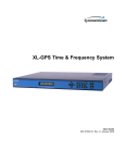
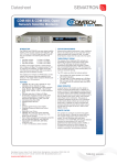
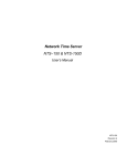
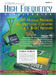
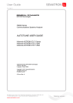
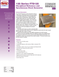
Datasheet
Rev A. Jan 12.
TIMING, TEST & MEASUREMENT
XL-GPS
Time and Frequency Receiver
•
•
KEY FEATURES
12 Channel GPS Receiver with TRAIM
Accurate to 30 Nanoseconds RMS
UTC (USNO)
•
Frequency Accuracy to 1x10-12
•
Vibrant LCD Display and Keypad
•
Time code reader/generator
•
•
•
•
•
•
•
•
•
•
•
•
Selectable Pulse Rates from 1PPS to
10 MPPS
10 MHz Frequency Output Standard
Ethernet Network Port
Telnet, SNMP and Serial Port for
Monitoring and Control
Network Time Server (NTP) Option
Option Module Bay Supports:
- Expansion Module
- Alarm Relay
- 1/5/10 MHz Frequency Module
- Multicode Time Code Module
Measurement Options
- Time Interval/Event Timing
- Frequency Measurement
KEY BENEFITS
12 channel GPS receiver
provides high accuracy UTC time and
frequency reference
Built-in network port facilitates
remote monitoring, configuration
and control
Easy setup via front panel display
and keypad
Multiple options available to extend
signal generation and measurement
capability
Robust time code generation supports
virtually any time code application
•
RoHS 5/6 Compliant
•
Remotely Software Upgradable
The XL-GPS Time and Frequency Receiver is a
high performance, cost effective GPS based
instrument that generates precise time and
frequency signals referenced to Coordinated
Universal Time (UTC). This high value,
networked managed instrument is an excellent
solution for test and measurement, central
timing systems, process automation, range
timing and power industry applications.
Easy configuration, control and monitoring is
provided with multiple user interfaces. The
bright LCD front panel display and keypad supports a convenient interface with at-a-glance
system status or time-of-day. The built-in
network port supports remote operation via
telnet and SNMP monitoring. Local control is
supported via a serial port and an alarm output
can drive an alarm monitoring system.
The XL-GPS is a part of Symmetricom’s ultra
precise model XLi time and frequency family of
products. The XL-GPS offers cost-effective
functionality and ease-of-use where the XLi
offers modularity and extensibility through
multiple option slots and modules.
A number of options are available to extend the
standard suite of functions to meet application
requirements. The Network Time Server (NTS)
option enables the XL-GPS to function as a
Stratum 1 Network Time Protocol (NTP) server
to synchronize networked computers and
devices.
At the XL-GPS core is a high performance disciplined oscillator. The internal, time optimized
GPS receiver provides exceptional accuracy for
time (< 30 nanoseconds to UTC) and frequency
(better than 1x10-12). A high performance oven
oscillator option is available for improved
stability and holdover performance.
A robust time code reader synchronizes to an
existing time code as an alternative or backup
to GPS. Time codes supported include IRIG A,
B; IEEE 1344, and NASA 36 in both amplitude
modulated and DC level shift formats.
The XL-GPS generates signals to synchronize
a broad array of time and frequency equipment.
Standard outputs include a 10 MHz sine wave,
and pulse rates from 1 pulse-per-second (PPS)
to 10 mega-pulses-per second (MPPS). A time
code generator output supports synchronization of remote devices.
The XL-GPS can optionally function as a
sophisticated measurement device to analyze
frequencies and pulses. The Frequency
Measurement (FM) option supports analysis of
1,5,10 MHz frequencies. The Time Interval/
Event Timing (TI/ET) option supports precise
event pulse time tagging and time interval
measurements with 5 nanosecond
resolution.
An option module bay is available to extend the
standard set of hardware outputs. The
Expansion Module provides independent time
code and pulse rate outputs. A 1,5,10 MHz/
MPPS module provides additional frequency
outputs. A Multicode module supports a wide
range of IRIG time codes.
The XL-GPS delivers advanced performance at
a lower cost with a versatile feature set to meet
the most demanding applications.
XL-GPS Time and Frequency Receiver
Sandpiper House, Aviary Court, Wade Road, Basingstoke, Hampshire, RG24 8GX, UK
T +44 (0) 1256 812 222 F +44 (0) 1256 812 666 E [email protected]
www.sematron.com
Making waves...
Datasheet
Rev A. Jan 12.
XL-GPS SPECIFICATIONS
•
•
GPS RECEIVER
Receiver input:
•
Tracking:
12 parallel channels. Multi satellite ensembling
with TRAIM.
•
Acquisition time:
Cold start <20 min. (typical)
•
1 PPS output accuracy:
Frequency output accuracy:
Frequency/timing Allan
Deviation stability:
UTC(USNO): ±30 nS RMS 100 ns peak
1 x 10-12 @ 1 day
•
•
TCXO (std)
OCXO (optional)
1 x 10⁻⁹ @ 1 sec
2 x 10⁻¹⁰ @ 1000 sec
1 x 10-12 @ 1 day
5x10⁻⁹/day
1 x 10⁻¹⁰ @ 1 sec
1 x 10⁻¹⁰ @ 1000 sec
1 x 10-12 @ 1 day
Aging
•
TIME CODE READER/GENERATOR
Codes:
IRIG A, B, IEEE 1344, NASA 36
•
STANDARD CPU INPUT/OUTPUT SIGNALS
Serial I/O
RS-232/422: User selectable up to 19.2 kbps
Connector: Male 9-pin D subminiature
•
Network interface:
Connector: BNC female
•
•
Power:
Operating temperature:
Storage temperature:
Humidity:
Display:
•
AM or DC code (IRIG-B120/B000; IEEE 1344,
NASA 36)
AM Code: 0.5 Vpp to 10 Vpp, 100 kΩ, ratio: 3:1 ±10%
Rate: 1 PPS, 10 PPS, 100 PPS, 1kPPS, 10kPPS,
100kPPS, 1 MPPS, 5 MPPS, 10 MPPS (default).
Duty cycle: 50% and 60/40%.
Amplitude: TTL into 50Ω
Connector: BNC female
Optional: Programmable Pulse Output (PPO)
•
J3 FM Input
Optional Frequency Measurement
Default: disabled.
1PPS Output:
•
•
Code out:
Format: AM or DC code (IRIG-B120/B000; IEEE
1344, NASA 36).
AM Code: 3 Vpp into 50Ω ±10%, ratio: 3:1 ±10%.
DC Code: TTL into 50Ω
Accuracy to 1PPS: AM ±10 usecs. DCLS ± 500
nsecs
Connector: BNC female (Below J2).
•
Alarm:
Open collector. Max 25V/50 mA.
Connector: BNC female (Below J3)
3” Dia. x 3” H (7.62 cm x 7.62 cm)
BNC female to GPS receiver. TNC on antenna
+12 Vdc
–55°C to +85°C (–67°F to +185°F)
–55°C to +85°C (–67°F to +185°F)
95%, non-condensing
UL, FCC, CE, RoHS 5/6, and C-UL
OPTIONS
Network Time Server (on standard network port)
•
•
Expansion Module
•
•
Alarm Relay
Frequency Measurement (FM)
Time Interval/Event Timing (TI/ET)
Programmable Pulse Output (PPO)
•
Extended cable lengths (75'-1500')
•
•
GPS In-line amplifier for extended cable runs up to 300' (91 m)
GPS Antenna down/up converter for long cable runs up to 1500’ (457 m)
Antenna splitter kit
•
Lightning arrestor
•
•
Impedance: 1kΩ or 50Ω
Standard 1PPS output
Pulse width: 20 µs (±1µs) on the rising edge
on-time. TTL into 50Ω.
Connector: BNC female (Below J1).
Antenna
Size:
Input:
Power:
Operating temperature:
Storage temperature:
Humidity:
Certification:
Voltage: 90–260 Vac, 110-300 VDC
Frequency: 47–63 Hz
IEC 320
1U: 1.75” x 17.1” x 15.35”
(4.44 cm x 43.4 cm x 38.9 cm)
Standard 19" (48.26 cm) EIA rack system,
hardware included.
0°C to +50°C (+32°F to +122°F)
–55°C to +85°C (–67°F to +185°F)
95%, non-condensing
Graphics (120 X 16) LCD. One line for time and day
of year (TOD). Two-line display for status messages
and user input.
Keypad: Includes: numeric 0–9, left, right,
up, down, CLR, Enter, time key, status key and
menu key.
Oscillator Upgrade: OCXO
1,5,10 MHz/MPPS Output Module
Multicode Output
•
•
Frequency: 1,5,10 MHz
Range: 1000 x10-6
•
MECHANICAL/ENVIRONMENTAL
Time and frequency system
Connector:
Size:
Connector: BNC female
Optional: TI/ET input
J2 Rate Output
Amplitude: >2V into 50Ω
Synchronization: +/- 20 nsecs to standard 1PPS
Connector: BNC female (Left of 10 MHz)
DC Code: Logic low <1.5 V, Logic Hi >2.5
Impedance: 100kΩ (AM) or 50Ω (DCLS)
Polarity: positive or negative
•
1PPS Output
Standard 10/100 Base-T, RJ-45.
Protocols: Telnet and SNMP for the user
interface, FTP (for firmware upgrades), Optional
NTP server
J1 Code input:
Synchronization: Coherent to standard 1PPS within
10 nsec
1575.42 MHz L1 C/A code. Coarse acquisition.
Position accuracy: typical 10 m RMS tracking
4 satellites.
•
•
DISCREET OUTPUT SIGNALS
10 MHz Output
Amplitude: +13dBm into 50Ω
•
XL-GPS Rear View (with Expansion Module)1530-602-1
SYMMETRICOM, INC.
2300 Orchard Parkway
San Jose, California
95131-1017
tel: 408.433.0910
fax: 408.428.7896
[email protected]
www.symmetricom.com
©2010 Symmetricom. Symmetricom and the Symmetricom logo are registered trademarks of Symmetricom, Inc. All other trademarks are the
property of their respective companies. All specifications subject to change without notice. DS/XLGPS/D/0510/PDF
Sandpiper House, Aviary Court, Wade Road, Basingstoke, Hampshire, RG24 8GX, UK
T +44 (0) 1256 812 222 F +44 (0) 1256 812 666 E [email protected]
www.sematron.com
Making waves...
Datasheet
Rev A. Jan 12.
XL-GPS Options
For Customizing the:
XL-GPS Time and Frequency Receiver
OPTIONS
•
Software:
Network Time Server
•
Frequency Measurement
•
Time Interval/Event Timing
•
Programmable Pulse Output
•
•
•
•
•
Hardware:
Oven Oscillator Upgrades
1, 5, 10 MHz/MPPS Frequency Outputs
Multicode Output for IRIG A, B, E, G, H;
XR3/2137 and NASA 36
Symmetricom makes it easy to configure the
XL-GPS Time and Frequency Receiver to
meet your specific application needs with
a variety of hardware and software options.
Whether your application demands network
time protocol service, measurement
capability or expanded time and frequency
outputs, all it takes is the proper
configuration of the instrument.
The powerful options make it easy to adapt
your XL-GPS configuration if your application needs change. The XL-GPS can
accommodate multiple software options
and one hardware option module. If additional outputs are required, the XLi Time
and Frequency System is a available in a 1U
and 2U chassis that supports up to 4 and 10
option modules respectively.
Not sure how to achieve what you want?
Simply call Symmetricom’s time and frequency
experts. You can also configure your own
XL-GPS system online at
www.symmetricom.com.
For more than 30 years Symmetricom has
defined premium time and synchronization
solutions. Put our expertise to work for you.
Expansion Module (4 outputs)
Expansion Module (4 outputs) with
Alarm Relay
XL-GPS Time and Frequency Receiver
XL-GPS Time and Frequency Receiver [back panel]
Sandpiper House, Aviary Court, Wade Road, Basingstoke, Hampshire, RG24 8GX, UK
T +44 (0) 1256 812 222 F +44 (0) 1256 812 666 E [email protected]
www.sematron.com
Making waves...
Datasheet
Rev A. Jan 12.
XL-GPS OPTIONS
Network Time Server on
Standard Network Port
No additional hardware is needed for this option; it utilizes
the XL-GPS standard network port, leaving the option slot
available.
SPECIFICATIONS: NETWORK TIME SERVER
OPTION 87-8017
•
• Synchronize servers and workstations across the network
• High-bandwidth NTP capability
• High availability time referenced to XL-GPS
• MD5 security protocol
• NTP broadcast mode
• SNMP Enterprise MIB
• Stratum 1 operation via GPS satellites
The high performance Symmetricom Network Time Server
(NTS) represents a breakthrough in network synchronization
technology. By combining a high-speed/high-capacity network
interface and a wide range of network protocol support,
XL-GPS seamlessly integrates into existing networks.
•
•
NETWORK PROTOCOLS
Network time protocols
NTP v3/v4 (RFC 1305)
SNTP (RFC 1769)
TIME (RFC 868)
MD5 (RFC 1321)
Other protocols
Telnet (RFC 854)
FTP (RFC 959)
MIB II (RFC 1213)
SNMP v2 Enterprise MIB II (RFC 1157)
Network transport protocol: TCP/IP
•
Simple Network Management Protocol (SNMP)
SNMP provides the network administrator with network status
and statistics. This feature implements SNMP versions 1 & 2 and
Management Information Base (MIB) I and II.
Network interface: 10/100 Base-T Ethernet
•
Network time accuracy: 1 to 10 mS typical
•
Accuracy: Function of input synchronization source (IRIG or GPS)
•
The NTS distributes time to precisely synchronize client computer clocks over a network. Time is acquired from the host
XL-GPS and distributed over the network using the Network
Time Protocol (NTP). Client computer clocks can be synchronized within milliseconds. Information on the health and status of the NTP server and the primary time synchronization
source is available by using the SNMP protocol Enterprise
MIB. Also, MD5 security protocol is included to authenticate
NTP client-server communication. The standard network port,
when factory enabled, serves as the NTP server via an RJ-45
Ethernet connector.
CLIENT SOFTWARE
An NTP client/daemon is required for client-side synchronization with any
network time server. Included with the NTP option is Symmetricom’s
SymmTime NTP client for Windows® 95/98/NT/2000/XP/Vista. Comprehensive
Domain Time II time client, server & management software for easy distribution, management and monitoring of time across the network is also available.
Programmable Pulse Output
The Programmable Pulse Output option is a software option
that provides a user configurable TTL level pulse output that
can be used to supply a precisely synchronized “trigger”
pulse at specific times or provide periodic pulse outputs. The
rising edge of the trigger output may be programmed with
microsecond resolution for fine control. The periodic pulse
rates supports several popular frequencies such as 1 PPS,
1 PP 10 SEC, 1 PPM, 1 PP 10 MIN, 1 PPH, 1 PP 10 HR,
1 PPD, 1 PP 10 DAYS or 1 PP 100 DAYS are available. The
pulse width is also programmable. The pulse is supplied via
a rear panel BNC.
SPECIFICATIONS: PROGRAMMABLE PULSE
OUTPUT (PPO) 87-8024
•
Range: 500kHz to 1 PP Year (integer multiples of 1 uS)
•
Pulse width: Programmable in 1µS steps up to 1 year
•
On time edge: Rising
•
Amplitude: TTL Levels into 50Ω
•
Accuracy: 200nSec
2
Sandpiper House, Aviary Court, Wade Road, Basingstoke, Hampshire, RG24 8GX, UK
T +44 (0) 1256 812 222 F +44 (0) 1256 812 666 E [email protected]
www.sematron.com
Making waves...
Datasheet
Rev A. Jan 12.
XL-GPS OPTIONS
Frequency Measurement
Time Interval/Event Timing
The Frequency Measurement is a software option that
provides the ability to precisely measure the frequency of
an externally applied 1, 5, or 10 MHz signal. Measurement
resolution is better than 120 x 10-12 with only a 1-second
averaging time. It supports a periodic, zero dead-time mode of
operation as well as a single-shot, measurement-on-demand
mode. The measurement interval can be specified in integer
seconds over the range of 1 to 100,000 seconds. Frequency
measurement results appear on the front panel display and
are output via the network and serial ports.
TIME INTERVAL
SPECIFICATIONS: FREQUENCY MEASUREMENT
87-8025
•
EVENT TIMING
The Event Timing feature offers the capability of locating
the time of occurrence of the rising edge of the applied
pulse with respect to the time of year. A “burst” mode provides
increased performance during short intervals. The collected
data is available via the serial or the Telnet port.
SPECIFICATIONS: TIME INTERVAL/EVENT
TIMING (TI/ET) 87-8026
INPUT FREQUENCIES
Keypad selectable frequencies of 1, 5, 10 MHz.
Input Level: 1.0 to 10 Vpp
Input Impedance: 1kΩ or 50Ω
Measurement Range: ±1 x 10⁻⁵ maximum offset; compares the external
frequency under test directly to the clock’s disciplined oscillator
Input Frequency: 1 MHz, 5 MHz, 10 MHz
Resolution:
120x10-12 @ 1 second
12x10-12 @ 10 seconds
1x10-12 @ 100 seconds
•
The Time Interval function is a software option that provides
the user with the ability to precisely measure the interval
between the time of occurrence of the clock-derived 1 Hz
reference pulse and the rising edge of the user-supplied
1 Hz pulse.
Accuracy:
•
INPUT FREQUENCIES
Rate: 1 PPS
•
High level: Logic Hi >1.25V <10V
•
Low level: Logic Low <1.25V >0V
•
Active edge: Rising (Positive)
•
Pulse width: 100 nS minimum
•
Input impedance: >1k, or 50Ω
•
TIME INTERVAL FEATURE
Measurement
TCXO
1x10⁻⁹ @ 1 second
2x10⁻¹⁰ @ 100 seconds
1x10-12 @ 1 day
Rate: 1 per second
Resolution: 5 nS
Accuracy: ±5 nS (+ clock accuracy**)
Range: 0.0 to 1 year
Ovenized quartz
1x10⁻¹⁰ @ 1 second
1x10⁻¹⁰ @ 100 second
1x10-12 @ 1 day
* Display: Time into the second, updated once per second, is displayed to the
nanosecond until another event occurs or until the “TIME”, “STATUS”, or
“POSITION” push-button is pressed.
•
EVENT TIMING FEATURE
Measurement
Rate: 10/second or 100/second burst
Resolution: 5 nS
Accuracy: ±5 nS (+ clock accuracy**)
Range: 0.0 to 1 year
* Display: Event Time occurrence, hundreds of days through nanoseconds, is
displayed until another event occurs or until the “TIME”, “STATUS”, or
“POSITION” push-button is pressed.
** For clock accuracy see accuracy of host unit.
3
Sandpiper House, Aviary Court, Wade Road, Basingstoke, Hampshire, RG24 8GX, UK
T +44 (0) 1256 812 222 F +44 (0) 1256 812 666 E [email protected]
www.sematron.com
Making waves...
Datasheet
Rev A. Jan 12.
XL-GPS OPTIONS
Multicode Output
Oscillators
Symmetricom’s XL-GPS receiver takes full advantage of the excellent long-term stability of the GPS system to steer or “discipline”
the instrument’s local oscillator. This process dramatically
enhances performance by removing the long-term aging
and drift of the oscillator without operator intervention.
Symmetricom provides a full spectrum of ultra-precise
frequency reference standards for every application. The
upgrades to the XL-GPS standard Temperature Compensated
Voltage Controlled Crystal Oscillator (TCVCXO) is the Ovenized
Crystal Oscillator (OCXO). For applications requiring higher
performance oscillators, the XLi offers rubidium atomic oscillators and high stability ovenized oscillators.
XL-GPS Disciplined Oscillator
GPS-XLi Disciplined Oscillator
Allan
AllanVariance
VarianceExample
(Typical)
• Programmable formats
• Up to four code outputs
• Codes available: IRIG A, B, E, G, H; XR3/2137 and NASA 36
Select the various time code formats by using any of the three
interfaces available: the front panel keypad and display, the
RS-232/422 serial port, or the standard network port. The
available time code format menu contains IRIG A, B, E, G, H;
XR3/2137, and NASA 36.
1E-09
SPECIFICATIONS: MULTICODE OUTPUT
87-6002-XL1
Allan Deviation
1E-10
•
Amplitude modulated;
Amplitude into 50Ω: 0–3 Vpp, adjustable via internally accessible
potentiometer
Amplitude into 600Ω: 0–10 Vpp, adjustable via internally accessible
potentiometer
Modulation ratio: 2:1 to 5:1 adjustable via internally accessible potentiometer
1E-11
1E-12
1E-13
10
100
1000
10000
100000
Tau (seconds)
TCXO
OCXO
Hi-Stab OCXO
•
Connector: BNC
•
Quantity: 4
•
Output impedance: 25Ω
•
Accuracy: Function of input synchronization source (GPS, IRIG)
•
Time codes
IRIG A 130 IRIG A 133 IRIG B 120
IRIG E 111 IRIG E 112 IRIG E 121
IRIG G 141 IRIG G 142 IRIG H 111
IRIG H 121 IRIG H 122 2137
NASA-36 (All codes in 24 hour format)
Rubidium
OSCILLATORS SPECIFICATIONS (TYPICAL)
•
TCVCXO (Standard in XL-GPS)
Accuracy: Function of input synchronization source (GPS, IRIG)
•
Frequency/timing Allan Deviation
•
Stability
IRIG B 123
IRIG E 122
IRIG H 112
XR-3
•
Time references: Standard, UTC, GPS, or Local
•
Compliance: RoHS Category 9 Exempt
1 x 10⁻⁹ @ 1 sec
2 x 10⁻¹⁰ @ 1000 sec
1 x 10–12 @ 24 hours
•
Temperature: 5 x 10⁻⁷, over 0°C to 50°C when not locked to a reference
•
OCXO OSCILLATOR OPTION 87-399-30
Accuracy: Function of input synchronization source (GPS, IRIG, 1PPS)
•
Frequency/timing Allan Deviation
Stability:
1 x 10⁻¹⁰ @ 1 sec
1 x 10⁻¹⁰ @ 1000 sec
1 x 10–12 @ 24 hours
•
Temperature: 1 x 10⁻⁸, over 0°C to 50°C when not locked to a reference
•
Aging: 5 x 10⁻⁹ per 24 hours
4
Sandpiper House, Aviary Court, Wade Road, Basingstoke, Hampshire, RG24 8GX, UK
T +44 (0) 1256 812 222 F +44 (0) 1256 812 666 E [email protected]
www.sematron.com
Making waves...
Datasheet
Rev A. Jan 12.
XL-GPS OPTIONS
1, 5, 10 MHz/MPPS
Expansion Module
The 1, 5, 10 MHz/MPPS Output card provides four precise sine
wave or square wave through four BNC outputs. These outputs
are phased-locked to the host receiver’s disciplined reference
oscillator. They are automatically enabled upon power-up, and
are independently selectable by the user with no configuration
setup required.
The Expansion Module is a versatile option that expands the number of
standard time code and pulse rate outputs from the XL-GPS. Four
independent, user configurable outputs are provided. The output signals are selectable via an on-module rotary switch. Specify output signal configuration at time of order. A version of the module is also available supporting an alarm relay output.
Outputs are preconfigured at the factory. Please specify
desired outputs on the sales order.
The available output signal types are as follows:
• Time Code AM/DC: Format mirrors XL-GPS standard code
output (IRIG A,B; IEEE 1344 or NASA 36)
• Alarm
• Rates (1 PPS, 1 kPPS, 10 kPPS, 100 kPPS, 1 MPPS,
5 MPPS,10 MPPS)
• Programmable Pulse (Requires PPO option to be installed)
• Alarm Relay (87-8134-2)
SPECIFICATIONS: 1, 5, 10 MHZ/MPPS OUTPUT
87-8108
•
1, 5, or 10 MHz OUTPUT
Amplitude: 1 Vrms into 50Ω
•
Harmonic distortion: –30 dBc
•
Synchronization: Phase locked to the clock 10 MHz
•
Accuracy: Function of input synchronization source (GPS, IRIG)
•
Connector: Female, BNC
SPECIFICATIONS:
- EXPANSION MODULE 87-8134-1
- EXPANSION MODULE W/ ALARM RELAY 87-8134-2
•
1, 5, or 10 MPPS OUTPUT
Amplitude: TTL into 50Ω
General
Connector: Female BNC
Quantity: 4
•
Duty cycle: 50%
•
Synchronization: Phase locked to the clock 10 MHz
•
•
Accuracy: Function of input synchronization source (GPS, IRIG)
•
•
•
•
•
•
•
•
•
•
•
•
•
•
Time Code
Format: IRIG A, B; IEEE 1344 or NASA 36
Amplitude (AM): 3.0 Vp-p +/-1V, into 50Ω
Ratio (AM): 3:1 +/- 10%
Amplitude (DC): TTL into 50Ω
Phasing: In phase with carrier ± 10µS
Alarm
Active High (Alarm state)
Amplitude: TTL Levels into 50Ω
Rates
Rate: 1 PPS, 1 kPPS, 10 kPPS, 100 kPPS, 1 MPPS, 5 MPPS, 10 MPPS
Duty cycle: 60/40% +/- 10%
Amplitude: TTL Levels into 50Ω
Programmable Pulse (Optional)
On time edge: Rising
Amplitude: TTL Levels into 50Ω
Alarm Relay 87-8134-2
Connection: Terminal strip, COM, NO, NC
Max Voltage: 48 VAC/VDC
Max Current: 2A @ 24 VDC
SYMMETRICOM, INC.
2300 Orchard Parkway
San Jose, California
95131-1017
tel: 408.433.0910
fax: 408.428.7896
[email protected]
www.symmetricom.com
©2010 Symmetricom. Symmetricom and the Symmetricom logo are registered trademarks of Symmetricom, Inc. All other trademarks are the
property of their respective companies. All specifications subject to change without notice. DS/XL-GPS OPTS/0510PDF
Sandpiper House, Aviary Court, Wade Road, Basingstoke, Hampshire, RG24 8GX, UK
T +44 (0) 1256 812 222 F +44 (0) 1256 812 666 E [email protected]
www.sematron.com
5
Making waves...