1
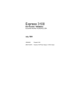
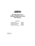
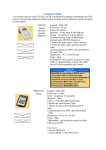
SM9256D/SM9234D/SM9232D Modems User’s Guide 520-01003-001 Rev .A The products and programs described in this User’s Guide are licensed products of Synxcom Corporation. This User’s Guide contains proprietary information protected by copyright, and this User’s Guide and all accompanying hardware and documentation are copyrighted. Synxcom Corporation does not warrant that the hardware will work properly in all environments and applications, and makes no warranty and representation, either implied or expressed, with respect to the quality, performance, merchantability, or fitness for a particular purpose. Synxcom Corporation will makes best efforts to update or keep current the information in this User’s Guide, and reserves the right to make changes to this User’s Guide and/or product without notice. No part of this manual may be reproduced or transmitted in any form or by any means, electronic or mechanical, including photocopying, recording, or information storage and retrieval systems, for any purpose other than the purchaser's personal use, without the express written permission of Synxcom Corporation. Copyright 2011 Synxcom Corporation. 1000 Dove Street, Suite 305 Newport Beach, California 92660 Tel: (949) 390-8236 Fax: (949) 872-2889 Web site: www.Synxcom.com FCC Requirements This device complies with Part 15 Class A of the FCC Rules. Operation is subject to the following two conditions: (1) this device may not cause harmful interference, and (2) this device must accept any interference received, including interference that may cause undesired operation. This equipment has been tested and found to comply with the limits for a Class A digital device, pursuant to Part 15 Class A of the FCC Rules. These limits are designed to provide reasonable protection against harmful interference in a residential installation. This equipment generates, uses, and can radiate radio frequency energy and, if not installed and used in accordance with the instructions, may cause harmful interference to radio communications. However, there is no guarantee that interference will not occur in a particular installation. If this equipment does cause harmful interference to radio or television reception, which can be determined by turning the equipment off and on, the user is encouraged to try to correct the interference by one or more of the following measures: Reorient or relocate the receiving antenna. Increase the separation between the equipment and the receiver. Connect the equipment to an outlet on a circuit other than the one to which the receiver is connected. Consult the dealer or an experienced radio/TV technician for help. If none of these actions resolves the problem, consult your distributor or an experienced radio/television technician for additional suggestions. Additionally, Section 15.838, paragraph d), of the FCC Rules and Regulations states: “Where special accessories, such as shielded cables, are required in order to meet FCC regulations, shielded cables must be used with this equipment. Operation with non-approved equipment or unshielded cables is likely to result in interference to radio and TV reception. The user is cautioned that changes and modifications to this equipment without the approval of the manufacturer could void the user’s authority to operate this equipment. Department of Canada Statement This Class A digital apparatus meets all requirements of the Canadian Interference-Causing Equipment Regulations. Cet appareil numerique de la classe A respecte toutes les exigences du Reglement sur le materiel brouilleur du Canada. Page iii FCC Part 68 Statement This equipment complies with the Federal Communications Commission’s (FCC) Rules and Regulations 47 CFR Part 68 and the Administrative Council on Terminal Attachments (ACTA) adopted technical criteria TIA/EIA/IS-968, Telecommunications – Telephone Terminal Equipment – Technical Requirements for Connection of Terminal Equipment To the Telephone Network, July 2001. On the plastic enclosure of this equipment is a label that contains the ACTA Registration number. You must, upon request, provide this information to your telephone company. This equipment uses USOCs RJ11 connector. A telephone cord and modular plug compliant with TIA/EIA/IS-968 are provided with this equipment. This equipment is designed to be connected to the telephone network or premises wiring using a compatible modular jack, which is Part 68 compliant. See installation instructions for details. The REN is useful to determine the quantity of devices you may connect to your telephone line and still have all those devices ring when your telephone number is called. In most, but not all areas, the sum of the REN's of all devices connected to one line should not exceed five (5.0). To be certain of the number of devices you may connect to your line, as determined by the REN, you should contact your local telephone company to determine the maximum REN for your calling area. (NOTE: REN are associated with loopstart and ground-start ports. Do not use for E&M or digital ports). If your telephone equipment causes harm to the telephone network, the Telephone Company may discontinue your service temporarily. If possible, they will notify you in advance. But if advance notice is not practical, you will be notified as soon as possible. You will be informed of your right to file a complaint with the FCC. Your telephone company may make changes in its facilities, equipment, operations or procedures that could affect the proper functioning of your equipment. If they do, you will be notified in advance to give you an opportunity to maintain uninterrupted telephone service. If you experience trouble with this telephone equipment, please contact Synxcom Corporation, 1000 Dove Street, Newport Beach, CA 92660, Phone (949) 677-6204 for information on obtaining service or repairs. The telephone company may ask that you disconnect this equipment from the network until the problem has been corrected or until you are sure that the equipment is not malfunctioning. Please note: No user serviceable parts contains in this equipment. This equipment may not be used on coin service provided by the telephone company. Connection to party lines is subject to state tariffs. The Telephone Consumer Protection Act of 1991 makes it unlawful for any person to use a computer or other electronic device, including fax machines, to send any message unless such message clearly contains in a margin at the top or bottom of each transmitted page or on the first page of the Transmission, the date and time it is sent and an identification of the business or other entity, or other individual sending the message and the telephone number of the sending machine or such business, other entity, or individual. Page iv (The telephone number provided may not be a 900 number or any other number for which charges exceeds local or long-distance transmission charges.) Page v Chapter 1 Introduction he Synxcom SM9256D, SM9234D and SM9232D are industrial grade standalone data/fax modem that deliver outstanding performance, transmitting data at the highest rates available over the public switched telephone networks (PSTN) today. The SM9256D, supports V.92 & V34 standards, offers asynchronous line speeds of up to 56kbps. The SM9234D supports V.34 and line speeds of up to 33.6kbps. The SM9232D supports V.32bis and line speeds of up to 14.4kbps. All modems incorporate the latest data compression and error correction standards and are capable of providing data throughput up to 230.4 kbps. The SM92xxD series modems incorporate advanced technology that enhances operation on less-than-ideal transmission lines. All modems also offer optional security features ideal for personal and corporate applications. The SM9256D easily handles tasks such as remote LAN access, telecommuting, remote file transfer, access to the Internet, and any other applications that require fast, reliable transmission speeds. T Features 2-wire unconditioned dial-up telephone line Build with industrial grade components to meet and operate under harsh environment ITU-V.92 capabilities, (model SM9256D) Compatible with ITU V.34, V.32bis, V.32, V.29, V.27ter, V.23, V.22bis, V.21, and V.17, Bell 212A/Bell 103. Maximum throughput may be up to 230.4KBPS using data compression Supports industry-standard AT command set Supports V.42 and MNP 2-4 error correction and V.42bis and MNP5 data compression Support RS-232 and RS-485 serial interface (user selectable) Support DC or battery powered operation by an isolated 10 to 60 VDC power supply Optional mounting kits for DIN rail mounting and wall/panel mounting Introduction Model Numbers and Order Information Model SM9256D: V92/V34/V32bis/V32/V22bis (56K) Stand-alone with AC power module 90 to 264 VAC or 100-400 VDC Model SM9256D-DC: V92/56K/V34/V32bis/V32/V22bis Stand-alone, DC power, 10-48 VDC Model SM9234D: V34/V32bis/V32/V22bis (33.6K) Stand-alone with AC power module 90 to 264 VAC or 100-400 VDC Model SM9234D-DC: V34/V32bis/V32/V22bis (33.6K) Stand-alone, DC power, 10-48 VDC Model SM9232D: V32bis/V32/V22bis (14.4K) Stand-alone with AC power module 90 to 264 VAC or 100-400 VDC Model SM9232D-DC: V32bis/V32/V22bis (14.4K) Stand-alone, DC power, 10-48 VDC Page 8 Introduction Mounting kit Accessories EN2-KIT-DIN: DIN Rail Mounting Kit for S/A units EN2-KIT-WMB: Wall-Panel mounting kit for S/A units Page 9 Introduction Chapter 2 Installation Unpacking Your Modem Your SM92xxD modem package includes the following items: One Synxcom SM9256D, SM9234D or SM9232D standalone modem An RJ-11 telephone cable An 115/230VAC AC to DC power supply converter (+12 Vdc, 800 ma Output) A DC power cable for the DC Power only version A CD containing the modem drivers and this User’s Guide Additional Items You Need To install the SM92xxD modems, you need the following additional items: The power source that matches the model you order, AC power module or 10-48VDC. A standard wall-mounted telephone jack (RJ-11C) located within 6 feet of your computer For RS-232 interface, a shielded serial cable with a 9-pin male connector for connecting to your SM92xxD. The connector on the other end of the cable should match the requirements of your computer or Data Terminal Equipment (DTE). For RS-485/RS422 interface, a RJ-11 serial cable connected to your RTU or DTE is required Note: If you use fax software, be sure it supports Class 1 fax operation. Page 10 Installation Setting-up and Installing Your Modem Configuring Your Modem’s DTE/RTU Interface. Your SM9256D and SM9234D support RTU/DTE with either RS-232 or RS-485 interface for communications. The modem is set to use the RS-232 interface (DB-9 connector) as the default interface from the factory. If you do not use RS-485/RS-422 option of the modem, skip this section and continue the installation with the “Installing You Modem” section below. To configure the modem for RS-485/RS-422 interface, you will need to connect your DTE/RTU to the RJ-11 connector as shown in Fig. 1 below and set up the DTE configuration DIP switches (SW1) provided on the modem PCB as indicated in the table below. DTE/RTU Interface SW-1 SW-2 SW-3 SW-4 SW-5 SW-6 RS-232 (DB-9) (default) OFF OFF OFF OFF OFF OFF RS-485 4-wire full duplex ON ON ON OFF OFF ON RS-485 2-wire half duplex OFF ON OFF ON ON OFF Note: Use a sharp pin to push and slide the DIP switches to the side labeled “ON” on the DIP switch is equivalent to CLOSE the switch. Figure 1 Configuration DIP Switch Page 11 Installation Installing Your Modem The following procedure describes how to install your SM92xxD modem. You perform these procedures using the connectors and jacks on the back of your SM9256D modem (see Fig. 2 on page 17). 1. Turn off your computer. 2. Disconnect the power connector on the back of your SM92xxD modem. 3. Connect one end of the DTE-DCE cable (no cross over cable) to your computer. Connect the other end of the cable to the DB-9 female connector on the back of your SM92xxD modem. 4. Connect either end of the supplied RJ-11 cable to a telephone wall jack. Connect the other end of the cable to the WALL jack on the back of your SM92xxD modem. 5. Connect the AC to DC power supply module to the modem. If DC power source is used, make sure the voltage range is within 10 to 48VDC. 6. Proceed to “Installing the Driver ” on the next page. Figure 2. SM92xxD Modem Back Panel Page 12 Installation Installing the Driver After you install your SM92xxD, use the appropriate procedure to install the modem driver. Windows XP If your computer contains the Microsoft Windows XP or Windows7 operating system, use the following procedure to install the modem driver. 1. Windows detects your SM9256D modem automatically. 2. In your computer’s CD-ROM drive, insert the supplied driver CD. 3. Click Install the software automatically [Recommended] if it’s not selected and click Next. 4. If a window tells you that the software you are installing for this hardware has not passed Windows Logo testing, click Continue Anyway. Windows installs the modem driver. 5. When the Completing the Found New Hardware Wizard appears, click Finish to complete the driver-installation procedure. Windows 2000 If your computer contains the Microsoft Windows 2000 operating system, use the following procedure to install the modem driver. 1. Windows detects your SM9256D modem automatically. 2. In your computer’s CD-ROM drive, insert the supplied driver CD. 3. Click Search for a suitable driver for my device [recommended] if it’s not selected and click Next. 4. Under Optional Search Locations, check CD-ROM drives if it is not checked and click Next. The Found New Hardware Wizard finds the driver for your modem. 5. Click Next to start the driver installation. 6. If a window tells you that the software you are installing for this hardware has not passed Windows Logo testing, click Yes to continue the installation. Windows installs the modem driver. 7. When the Completing the Found New Hardware Wizard appears, click Finish to complete the driver-installation procedure. Page 13 Installation LEDs The SM9256D modem provides six LED indicators. Table 2-6 lists the modem LED indicators. Table 2-6. LEDs Indicating Modem Control Signals LED DTR TD RD DCD MR RI DTE Signal Data Terminal Ready Transmitted Data Received Data Data Carrier Detect Modem Ready Ring Indicator Modem Operation Before you start using the modem, you must set up the modem to match your DTE&RTU configurations. Parameters such as the following are important to consider: • • • • Serial port data speed when originate a connection or answering a call Method for the DTE to originate a call (AT dial string or DTR signaling, etc,) Enable or disable the auto-answer mode when a ring signal is received Flow control for your DTE or RTU, in any is used Serial Port Data Speed The modem is set to auto-speed detect (auto baud) in default mode. When a AT string is received, it will set its speed and character format automatically to match the terminal speed until the power is recycled or reset. If the modem is in answering mode only, it is necessary to configure the DTE speed to match with the connected DTE such that proper communications will take place once it auto-answer an incoming call. Please refer to commands for AT+IPR for further details. Auto-Answer Mode By default, the SM92xxD modem is set up to not auto-answer incoming calls. If you want the modem to answer calls automatically, set the S0 register to a value other than its default value of Page 14 Installation zero. For example, issuing the AT command ATS0=1 configures the modem to auto-answer calls after the first ring. These commands are typed from your computer or DTE keyboard using terminal-emulation software such as HyperTerminal. If you change the auto-answer parameter, the new setting remains in effect until your modem is powered-off. The next time your modem is powered-up, auto-answer is disabled again. To keep auto-answer enabled each time the modem is powered-up, use the AT&W command to save your changes in the modem’s nonvolatile memory. For more information about using this command to store AT commands in nonvolatile memory, refer to the &W command on pages followed. Page 15 Installation Call Answer Testing After powering-on the SM92xxD modem, use the following procedure to test the modem’s ability to answer a call. 1. Configure your SM92xxD modem to auto-answer incoming calls, as described under “Modem Operation” on page 13. 2. Use a telephone to call the SM92xxD modem. Listen to the call to verify that the SM9256D modem answers the call with its answer tone and performs its handshaking sequence in an attempt to make a data connection. Hang up the handset of the telephone that originated the call. 3. Use another modem to call the SM9256D modem. Verify that the SM9256D modem answers the call, makes a data connection, and turns on the MR and DCD LEDs. Call Originating Testing Use the following procedure to test the modem’s ability to place a call. 1. Using terminal-emulation software such as HyperTerminal, issue the AT command ATD<your number> where <your number> is the telephone number your modem is connected to. For example, if your modem is connected to the line 555-1212, type ATD5551212. 2. You should hear the modem originate the call followed by a busy signal (since the modem is dialing its own number). In addition, a BUSY result code should appear on the computer or DTE monitor. If you do not hear the modem placing the call, use the ATL and ATM commands to adjust the volume and status of the modem speaker. For more information about these commands, refer to page Error! Bookmark not defined.. Note: If you try to establish a V.90 or V.92 connection, be sure the remote modem also supports V.90 or V.92. Otherwise, you will not be able to establish the connection. Page 16 Installation NOTES Page 17 Chapter 3 Using the Modem’s Security Features This section is available with the security modems only Contact Synxcom’s Technical Support for information for specifications for Security modems for the PSTN networks AT Commands Page 19 AT Commands Appendix A AT Commands Please refer to separate AT command set document provided with the modem. Page 20 Limited Product Warranty Appendix B Limited Product Warranty Synxcom warrants that the Product sold will be free from defects in material and workmanship and perform to Synxcom' applicable published specifications for a period of 18 months from the date of delivery to Customer or 12 months from placement into service, whichever occurs first. The liability of Synxcom hereunder shall be limited to replacing or repairing, at its option, any defective Products which are returned F.O.B., Synxcom' facility, Newport Beach, California (or, at Synxcom' option refunding the purchase price of such products). In no case are Products to be returned without first obtaining permission and a customer return order number from Synxcom. In no event shall Synxcom be liable for any consequential or incidental damages. Products which have been subject to abuse, misuse, accident, alteration, neglect, unauthorized repair or installation are not covered by the warranty. Synxcom shall make the final determination as to the existence and cause of any alleged defect. No liability is assumed for expendable items such as lamps and fuses. No warranty is made with respect to custom products or Products produced to Customer's specifications except as specifically stated in writing by Synxcom in the agreement for such custom products. This warranty is the only warranty made by Synxcom with respect to the goods delivered hereunder, and may be modified or amended only by a written instrument signed by a duly authorized officer or Synxcom and accepted by Customer. This warranty and limitation extends to customer and to users of the product and is in lieu of all warranties with respect to the product whether express, implied, or statutory, including without limitation the implied warranties of merchantability and fitness for a particular purpose. RMA Procedure Appendix C Return Merchandise Authorization (RMA) Procedure Before returning any Synxcom product, an RMA number must be obtained. Before asking for an RMA number, ascertain that the product was purchased from Synxcom. If you bought the product from a Distributor or Systems Integrator, the product should be returned to that vendor. The most convenient method to obtain an RMA number for a product purchased from Synxcom is to send an email to mailto:[email protected]. Information required must include your company name, address, the actual address that we would use to return the product to you. Please include any Mail Stop or specific delivery information. The city, state, and zip code are all required. Your phone and FAX numbers. Your email address. If the above information is on your letterhead, that format is acceptable. For each item you wish to return: List the product model number, usually found on the serial number tag, the serial number for each item you wish to return, a description of the problem you are encountering, and the cause of the problem (if known). A product support specialist may call to verify that the product is properly installed or may ask you to perform tests to insure that the product has actually failed. After review of the problem, an RMA number will be assigned, you will be notified by email or FAX. The product must be properly packed and returned to: Synxcom Inc. 1000 Dove Street, Suite 305 Newport Beach, CA 92660 Attn: Technical Support The RMA number must be legibly displayed on the shipping carton. No RMAs will be issued without a product review, Synxcom will not be responsible for any product returned without an RMA number. In the near future the RMA form will be available on our Web site Synxcom.com/support/rma. Fill in all blanks and click on the “Submit” button. If you think the product may be out of warranty, include a method of payment for repairs, either a Purchase Order number, or Credit card number, Card Holder Name, Date of Expiration on the RMA request. Repairs currently require 5 – 10 working days, and are returned UPS second day air.