1
PDT 7500 Series
Product Reference Guide
PDT 7500 Series Product Reference Guide
72-39225-02
Revision A — October 2001
Symbol Technologies, Inc. One Symbol Plaza, Holtsville N.Y. 11742-1300
PDT 7500 Series
Product Reference Guide for DOS
72-39225-02
Revision A
October 2001
2001 by Symbol Technologies, Inc. All rights reserved.
No part of this publication may be reproduced or used in any form, or by any electrical or
mechanical means, without permission in writing from Symbol. This includes electronic or
mechanical means, such as photocopying, recording, or information storage and retrieval
systems. The material in this manual is subject to change without notice.
The software is provided strictly on an “as is” basis. All software, including firmware,
furnished to the user is on a licensed basis. Symbol grants to the user a non-transferable and
non-exclusive license to use each software or firmware program delivered hereunder (licensed
program). Except as noted below, such license may not be assigned, sublicensed, or otherwise
transferred by the user without prior written consent of Symbol. No right to copy a licensed
program in whole or in part is granted, except as permitted under copyright law. The user
shall not modify, merge, or incorporate any form or portion of a licensed program with other
program material, create a derivative work from a licensed program, or use a licensed
program in a network without written permission from Symbol. The user agrees to maintain
Symbol’s copyright notice on the licensed programs delivered hereunder, and to include the
same on any authorized copies it makes, in whole or in part. The user agrees not to
decompile, disassemble, decode, or reverse engineer any licensed program delivered to the
user or any portion thereof.
Symbol reserves the right to make changes to any software or product to improve reliability,
function, or design.
Symbol does not assume any product liability arising out of, or in connection with, the
application or use of any product, circuit, or application described herein.
No license is granted, either expressly or by implication, estoppel, or otherwise under any
Symbol Technologies, Inc., intellectual property rights. An implied license only exists for
equipment, circuits, and subsystems contained in Symbol products.
Symbol, Spectrum One, and Spectrum24 are registered trademarks of Symbol Technologies,
Inc. Other product names mentioned in this manual may be trademarks or registered
trademarks of their respective companies and are hereby acknowledged.
Symbol Technologies, Inc.
One Symbol Plaza
Holtsville, New York 11742-1300
http://www.symbol.com
Contents
About This Guide
Introduction . . . . . . . . . . . . . . . . . . . . . . . . . . . . . . . . . . . . . . . . . . . . . . . . . . . . . . . . . . . . . . . . . . . .ix
Chapter Descriptions . . . . . . . . . . . . . . . . . . . . . . . . . . . . . . . . . . . . . . . . . . . . . . . . . . . . . . . . . . . . .ix
Notational Conventions . . . . . . . . . . . . . . . . . . . . . . . . . . . . . . . . . . . . . . . . . . . . . . . . . . . . . . . . . . . x
Related Publications . . . . . . . . . . . . . . . . . . . . . . . . . . . . . . . . . . . . . . . . . . . . . . . . . . . . . . . . . . . . . .xi
Service Information . . . . . . . . . . . . . . . . . . . . . . . . . . . . . . . . . . . . . . . . . . . . . . . . . . . . . . . . . . . . . .xi
Symbol Support Centers . . . . . . . . . . . . . . . . . . . . . . . . . . . . . . . . . . . . . . . . . . . . . . . . . . . . . . xii
Warranty . . . . . . . . . . . . . . . . . . . . . . . . . . . . . . . . . . . . . . . . . . . . . . . . . . . . . . . . . . . . . . . . . . . . .xiv
Warranty Coverage and Procedure . . . . . . . . . . . . . . . . . . . . . . . . . . . . . . . . . . . . . . . . . . . . . . xv
General . . . . . . . . . . . . . . . . . . . . . . . . . . . . . . . . . . . . . . . . . . . . . . . . . . . . . . . . . . . . . . . . . . . xv
Chapter 1. Getting Started
Chapter Contents . . . . . . . . . . . . . . . . . . . . . . . . . . . . . . . . . . . . . . . . . . . . . . . . . . . . . . . . . . . . . .
Introduction . . . . . . . . . . . . . . . . . . . . . . . . . . . . . . . . . . . . . . . . . . . . . . . . . . . . . . . . . . . . . . . . . .
The PDT 7500 Series. . . . . . . . . . . . . . . . . . . . . . . . . . . . . . . . . . . . . . . . . . . . . . . . . . . . . . . .
Unpacking the Terminal . . . . . . . . . . . . . . . . . . . . . . . . . . . . . . . . . . . . . . . . . . . . . . . . . . . . . . . . .
Parts of the Terminal . . . . . . . . . . . . . . . . . . . . . . . . . . . . . . . . . . . . . . . . . . . . . . . . . . . . . . . . . . .
Accessories and Peripherals . . . . . . . . . . . . . . . . . . . . . . . . . . . . . . . . . . . . . . . . . . . . . . . . . . . . . .
Holster . . . . . . . . . . . . . . . . . . . . . . . . . . . . . . . . . . . . . . . . . . . . . . . . . . . . . . . . . . . . . . . . . .
Handstrap . . . . . . . . . . . . . . . . . . . . . . . . . . . . . . . . . . . . . . . . . . . . . . . . . . . . . . . . . . . . . . . .
Battery Packs. . . . . . . . . . . . . . . . . . . . . . . . . . . . . . . . . . . . . . . . . . . . . . . . . . . . . . . . . . . . . .
Cables . . . . . . . . . . . . . . . . . . . . . . . . . . . . . . . . . . . . . . . . . . . . . . . . . . . . . . . . . . . . . . . . . . .
Power Supply . . . . . . . . . . . . . . . . . . . . . . . . . . . . . . . . . . . . . . . . . . . . . . . . . . . . . . . . . . . . .
Stylus . . . . . . . . . . . . . . . . . . . . . . . . . . . . . . . . . . . . . . . . . . . . . . . . . . . . . . . . . . . . . . . . . . .
PDT 753X WAN Terminals . . . . . . . . . . . . . . . . . . . . . . . . . . . . . . . . . . . . . . . . . . . . . . . . . .
PDT 754X Spectrum24 Radio Terminals . . . . . . . . . . . . . . . . . . . . . . . . . . . . . . . . . . . . . . . .
SDK . . . . . . . . . . . . . . . . . . . . . . . . . . . . . . . . . . . . . . . . . . . . . . . . . . . . . . . . . . . . . . . . . . . .
Before You Use the Terminal . . . . . . . . . . . . . . . . . . . . . . . . . . . . . . . . . . . . . . . . . . . . . . . . . . . . .
Install and Charge Battery Pack. . . . . . . . . . . . . . . . . . . . . . . . . . . . . . . . . . . . . . . . . . . . . . . .
Configure the Terminal . . . . . . . . . . . . . . . . . . . . . . . . . . . . . . . . . . . . . . . . . . . . . . . . . . . . . .
1-1
1-3
1-3
1-3
1-4
1-5
1-6
1-6
1-6
1-6
1-6
1-6
1-6
1-7
1-7
1-7
1-7
1-8
iii
PDT 7500 Series Product Reference Guide for DOS
Run Setup. . . . . . . . . . . . . . . . . . . . . . . . . . . . . . . . . . . . . . . . . . . . . . . . . . . . . . . . . . . . . . . . . 1-8
Chapter 2. Software Installation on the Development PC
Chapter Contents. . . . . . . . . . . . . . . . . . . . . . . . . . . . . . . . . . . . . . . . . . . . . . . . . . . . . . . . . . . . . . . 2-1
Introduction. . . . . . . . . . . . . . . . . . . . . . . . . . . . . . . . . . . . . . . . . . . . . . . . . . . . . . . . . . . . . . . . . . . 2-3
DOS . . . . . . . . . . . . . . . . . . . . . . . . . . . . . . . . . . . . . . . . . . . . . . . . . . . . . . . . . . . . . . . . . . . . . . . . 2-3
Spectrum24 NDK . . . . . . . . . . . . . . . . . . . . . . . . . . . . . . . . . . . . . . . . . . . . . . . . . . . . . . . . . . . . . . 2-4
Installing the SDK on the Development PC . . . . . . . . . . . . . . . . . . . . . . . . . . . . . . . . . . . . . . . . . . . 2-4
Installing Other Development Software . . . . . . . . . . . . . . . . . . . . . . . . . . . . . . . . . . . . . . . . . . . . . . 2-4
Chapter 3. Cradle Setup and Operation
Chapter Contents. . . . . . . . . . . . . . . . . . . . . . . . . . . . . . . . . . . . . . . . . . . . . . . . . . . . . . . . . . . . . . . 3-1
Introduction. . . . . . . . . . . . . . . . . . . . . . . . . . . . . . . . . . . . . . . . . . . . . . . . . . . . . . . . . . . . . . . . . . . 3-3
Parts of the CRD 7500 Single-Slot Cradle . . . . . . . . . . . . . . . . . . . . . . . . . . . . . . . . . . . . . . . . . . . . 3-3
Parts of the CRD 7500 Four-Slot Cradle . . . . . . . . . . . . . . . . . . . . . . . . . . . . . . . . . . . . . . . . . . . . . 3-4
Parts of the VCD 7500 Vehicle Cradle. . . . . . . . . . . . . . . . . . . . . . . . . . . . . . . . . . . . . . . . . . . . . . . 3-5
Setting Up the CRD 7500 Single and Four-Slot Cradles. . . . . . . . . . . . . . . . . . . . . . . . . . . . . . . . . . 3-6
Connecting Power . . . . . . . . . . . . . . . . . . . . . . . . . . . . . . . . . . . . . . . . . . . . . . . . . . . . . . . . . . 3-6
Connecting the RS-232 Cable to a Host Computer . . . . . . . . . . . . . . . . . . . . . . . . . . . . . . . . . 3-7
Setting Up the VCD 7500 Vehicle Cradle . . . . . . . . . . . . . . . . . . . . . . . . . . . . . . . . . . . . . . . . . . . . 3-7
Installing the VCD 7500 Cradle . . . . . . . . . . . . . . . . . . . . . . . . . . . . . . . . . . . . . . . . . . . . . . . . 3-7
Connecting the VCD 7500 Vehicle Cradle a Host Computer . . . . . . . . . . . . . . . . . . . . . . . . . . 3-9
Sending Data . . . . . . . . . . . . . . . . . . . . . . . . . . . . . . . . . . . . . . . . . . . . . . . . . . . . . . . . . . . . . 3-10
Cradle Self Test . . . . . . . . . . . . . . . . . . . . . . . . . . . . . . . . . . . . . . . . . . . . . . . . . . . . . . . . . . . . . . . 3-10
Batteries. . . . . . . . . . . . . . . . . . . . . . . . . . . . . . . . . . . . . . . . . . . . . . . . . . . . . . . . . . . . . . . . . . . . . 3-10
Battery Life. . . . . . . . . . . . . . . . . . . . . . . . . . . . . . . . . . . . . . . . . . . . . . . . . . . . . . . . . . . . . . . 3-11
Backup Battery . . . . . . . . . . . . . . . . . . . . . . . . . . . . . . . . . . . . . . . . . . . . . . . . . . . . . . . . . . . . 3-11
Installing a New or Recharged Battery . . . . . . . . . . . . . . . . . . . . . . . . . . . . . . . . . . . . . . . . . . 3-11
Removing the Battery . . . . . . . . . . . . . . . . . . . . . . . . . . . . . . . . . . . . . . . . . . . . . . . . . . . . . . . 3-12
Replacing the Battery in an Active Terminal. . . . . . . . . . . . . . . . . . . . . . . . . . . . . . . . . . . . . . 3-13
Charging the Battery . . . . . . . . . . . . . . . . . . . . . . . . . . . . . . . . . . . . . . . . . . . . . . . . . . . . . . . . . . . 3-14
Charging the Battery in Cradle . . . . . . . . . . . . . . . . . . . . . . . . . . . . . . . . . . . . . . . . . . . . . . . . 3-14
Charging the Battery Via Power Supply . . . . . . . . . . . . . . . . . . . . . . . . . . . . . . . . . . . . . . . . . 3-14
Charging the Spare Battery in the Cradle . . . . . . . . . . . . . . . . . . . . . . . . . . . . . . . . . . . . . . . . 3-15
Chapter 4. Operating the Terminal
Chapter Contents. . . . . . . . . . . . . . . . . . . . . . . . . . . . . . . . . . . . . . . . . . . . . . . . . . . . . . . . . . . . . . . 4-1
Introduction. . . . . . . . . . . . . . . . . . . . . . . . . . . . . . . . . . . . . . . . . . . . . . . . . . . . . . . . . . . . . . . . . . . 4-2
Powering on the PDT 7500 . . . . . . . . . . . . . . . . . . . . . . . . . . . . . . . . . . . . . . . . . . . . . . . . . . . . . . . 4-2
Booting the Terminal . . . . . . . . . . . . . . . . . . . . . . . . . . . . . . . . . . . . . . . . . . . . . . . . . . . . . . . . . . . . 4-3
Suspending and Resuming Operation . . . . . . . . . . . . . . . . . . . . . . . . . . . . . . . . . . . . . . . . . . . . . . . 4-3
iv
Contents
Adjusting the Display and Volume . . . . . . . . . . . . . . . . . . . . . . . . . . . . . . . . . . . . . . . . . . . . . . . . . 4-4
Scanning . . . . . . . . . . . . . . . . . . . . . . . . . . . . . . . . . . . . . . . . . . . . . . . . . . . . . . . . . . . . . . . . . . . . . 4-5
Using the Scanner . . . . . . . . . . . . . . . . . . . . . . . . . . . . . . . . . . . . . . . . . . . . . . . . . . . . . . . . . . 4-5
Scanning Considerations . . . . . . . . . . . . . . . . . . . . . . . . . . . . . . . . . . . . . . . . . . . . . . . . . . . . . 4-6
Smart Raster Capability . . . . . . . . . . . . . . . . . . . . . . . . . . . . . . . . . . . . . . . . . . . . . . . . . . . . . 4-7
Scanning Mode Options . . . . . . . . . . . . . . . . . . . . . . . . . . . . . . . . . . . . . . . . . . . . . . . . . . . . . 4-8
Scanning PDF417 Bar Codes . . . . . . . . . . . . . . . . . . . . . . . . . . . . . . . . . . . . . . . . . . . . . . . . . . 4-8
Scanning (Imager). . . . . . . . . . . . . . . . . . . . . . . . . . . . . . . . . . . . . . . . . . . . . . . . . . . . . . . . . . . . . 4-11
Scanning . . . . . . . . . . . . . . . . . . . . . . . . . . . . . . . . . . . . . . . . . . . . . . . . . . . . . . . . . . . . . . . . 4-11
Operational Modes . . . . . . . . . . . . . . . . . . . . . . . . . . . . . . . . . . . . . . . . . . . . . . . . . . . . . . . . 4-12
Aiming the Imager. . . . . . . . . . . . . . . . . . . . . . . . . . . . . . . . . . . . . . . . . . . . . . . . . . . . . . . . . 4-12
Performing Communications . . . . . . . . . . . . . . . . . . . . . . . . . . . . . . . . . . . . . . . . . . . . . . . . . . . . 4-14
Communicating via RS-232 Cable. . . . . . . . . . . . . . . . . . . . . . . . . . . . . . . . . . . . . . . . . . . . . 4-14
Communicating via Cradle . . . . . . . . . . . . . . . . . . . . . . . . . . . . . . . . . . . . . . . . . . . . . . . . . . 4-14
Spectrum24 Communications . . . . . . . . . . . . . . . . . . . . . . . . . . . . . . . . . . . . . . . . . . . . . . . . 4-15
Chapter 5. Terminal Configuration: Edit the Configuration Files
Chapter Contents . . . . . . . . . . . . . . . . . . . . . . . . . . . . . . . . . . . . . . . . . . . . . . . . . . . . . . . . . . . . . . 5-1
Setup/Edit DOS Configuration Files . . . . . . . . . . . . . . . . . . . . . . . . . . . . . . . . . . . . . . . . . . . . . . . . 5-3
CONFIG.SYS . . . . . . . . . . . . . . . . . . . . . . . . . . . . . . . . . . . . . . . . . . . . . . . . . . . . . . . . . . . . . 5-3
AUTOEXEC.BAT . . . . . . . . . . . . . . . . . . . . . . . . . . . . . . . . . . . . . . . . . . . . . . . . . . . . . . . . . . 5-8
Symbol-Supplied TSRs and Device Drivers . . . . . . . . . . . . . . . . . . . . . . . . . . . . . . . . . . . . . . . 5-8
Symbol-Supplied Utilities. . . . . . . . . . . . . . . . . . . . . . . . . . . . . . . . . . . . . . . . . . . . . . . . . . . . 5-10
Symbol-Supplied Network Configuration Files . . . . . . . . . . . . . . . . . . . . . . . . . . . . . . . . . . . 5-12
Chapter 6. Terminal Configuration: Build and Send the Hex Image
Chapter Contents . . . . . . . . . . . . . . . . . . . . . . . . . . . . . . . . . . . . . . . . . . . . . . . . . . . . . . . . . . . . . . 6-1
Overview . . . . . . . . . . . . . . . . . . . . . . . . . . . . . . . . . . . . . . . . . . . . . . . . . . . . . . . . . . . . . . . . . . . . 6-3
Starting Terminal Configuration Manager . . . . . . . . . . . . . . . . . . . . . . . . . . . . . . . . . . . . . . . . . . . 6-4
Defining Script Properties . . . . . . . . . . . . . . . . . . . . . . . . . . . . . . . . . . . . . . . . . . . . . . . . . . . . . . . . 6-6
Creating the Script for the Hex Image . . . . . . . . . . . . . . . . . . . . . . . . . . . . . . . . . . . . . . . . . . . . . . 6-8
Open a New or Existing Script . . . . . . . . . . . . . . . . . . . . . . . . . . . . . . . . . . . . . . . . . . . . . . . . 6-8
Copy Components to the Script. . . . . . . . . . . . . . . . . . . . . . . . . . . . . . . . . . . . . . . . . . . . . . . . 6-9
Save the Script . . . . . . . . . . . . . . . . . . . . . . . . . . . . . . . . . . . . . . . . . . . . . . . . . . . . . . . . . . . . . 6-9
Building the Image . . . . . . . . . . . . . . . . . . . . . . . . . . . . . . . . . . . . . . . . . . . . . . . . . . . . . . . . . . . . 6-10
Sending the Hex Image . . . . . . . . . . . . . . . . . . . . . . . . . . . . . . . . . . . . . . . . . . . . . . . . . . . . . . . . . 6-12
Loading the BIOS . . . . . . . . . . . . . . . . . . . . . . . . . . . . . . . . . . . . . . . . . . . . . . . . . . . . . . . . . 6-12
Saving the Script . . . . . . . . . . . . . . . . . . . . . . . . . . . . . . . . . . . . . . . . . . . . . . . . . . . . . . . . . . 6-12
Connect The Terminal and Development PC. . . . . . . . . . . . . . . . . . . . . . . . . . . . . . . . . . . . . 6-12
Begin the Send in TCM . . . . . . . . . . . . . . . . . . . . . . . . . . . . . . . . . . . . . . . . . . . . . . . . . . . . . 6-13
Initial Program Loader (IPL). . . . . . . . . . . . . . . . . . . . . . . . . . . . . . . . . . . . . . . . . . . . . . . . . . . . . 6-14
Using the Keyboard . . . . . . . . . . . . . . . . . . . . . . . . . . . . . . . . . . . . . . . . . . . . . . . . . . . . . . . . 6-14
v
PDT 7500 Series Product Reference Guide for DOS
Using the Touch Screen . . . . . . . . . . . . . . . . . . . . . . . . . . . . . . . . . . . . . . . . . . . . . . . . . . . . . 6-15
Invoking IPL . . . . . . . . . . . . . . . . . . . . . . . . . . . . . . . . . . . . . . . . . . . . . . . . . . . . . . . . . . . . . 6-15
Restarting after Download Fails . . . . . . . . . . . . . . . . . . . . . . . . . . . . . . . . . . . . . . . . . . . . . . . 6-22
Exiting IPL . . . . . . . . . . . . . . . . . . . . . . . . . . . . . . . . . . . . . . . . . . . . . . . . . . . . . . . . . . . . . . . 6-22
Exiting TCM . . . . . . . . . . . . . . . . . . . . . . . . . . . . . . . . . . . . . . . . . . . . . . . . . . . . . . . . . . . . . 6-23
Chapter 7. Terminal Configuration: Load a RAM Disk
Chapter Contents. . . . . . . . . . . . . . . . . . . . . . . . . . . . . . . . . . . . . . . . . . . . . . . . . . . . . . . . . . . . . . . 7-1
Loading a RAM Disk. . . . . . . . . . . . . . . . . . . . . . . . . . . . . . . . . . . . . . . . . . . . . . . . . . . . . . . . . . . . 7-3
Standard RAM Disk Driver . . . . . . . . . . . . . . . . . . . . . . . . . . . . . . . . . . . . . . . . . . . . . . . . . . . 7-3
Multiple RAM Disks . . . . . . . . . . . . . . . . . . . . . . . . . . . . . . . . . . . . . . . . . . . . . . . . . . . . . . . . 7-3
Chapter 8. Terminal Configuration: Setup
Chapter Contents. . . . . . . . . . . . . . . . . . . . . . . . . . . . . . . . . . . . . . . . . . . . . . . . . . . . . . . . . . . . . . . 8-1
Introduction. . . . . . . . . . . . . . . . . . . . . . . . . . . . . . . . . . . . . . . . . . . . . . . . . . . . . . . . . . . . . . . . . . . 8-3
Navigating Setup . . . . . . . . . . . . . . . . . . . . . . . . . . . . . . . . . . . . . . . . . . . . . . . . . . . . . . . . . . . 8-3
Invoking Setup . . . . . . . . . . . . . . . . . . . . . . . . . . . . . . . . . . . . . . . . . . . . . . . . . . . . . . . . . . . . . 8-3
Chapter 9. Terminal Configuration: Setting Up PCMCIA Cards
Chapter Contents. . . . . . . . . . . . . . . . . . . . . . . . . . . . . . . . . . . . . . . . . . . . . . . . . . . . . . . . . . . . . . . 9-1
PCMCIA Cards . . . . . . . . . . . . . . . . . . . . . . . . . . . . . . . . . . . . . . . . . . . . . . . . . . . . . . . . . . . . . . . . 9-3
Formatting PCMCIA Cards . . . . . . . . . . . . . . . . . . . . . . . . . . . . . . . . . . . . . . . . . . . . . . . . . . . 9-3
Moving Files to PCMCIA Card . . . . . . . . . . . . . . . . . . . . . . . . . . . . . . . . . . . . . . . . . . . . . . . . 9-4
Using DRVSPACE to Extend Storage on PCMCIA Cards . . . . . . . . . . . . . . . . . . . . . . . . . . . . 9-4
vi
Contents
Chapter 10. Maintenance and Troubleshooting
Chapter Contents . . . . . . . . . . . . . . . . . . . . . . . . . . . . . . . . . . . . . . . . . . . . . . . . . . . . . . . . . . . . .
Cleaning the Terminal . . . . . . . . . . . . . . . . . . . . . . . . . . . . . . . . . . . . . . . . . . . . . . . . . . . . . . . . .
Storage . . . . . . . . . . . . . . . . . . . . . . . . . . . . . . . . . . . . . . . . . . . . . . . . . . . . . . . . . . . . . . . . . . . . .
Terminal Troubleshooting . . . . . . . . . . . . . . . . . . . . . . . . . . . . . . . . . . . . . . . . . . . . . . . . . . . . . .
Cradle Problems . . . . . . . . . . . . . . . . . . . . . . . . . . . . . . . . . . . . . . . . . . . . . . . . . . . . . . . . . . . . . .
10-1
10-3
10-3
10-4
10-6
Appendix A. Specifications
Environment. . . . . . . . . . . . . . . . . . . . . . . . . . . . . . . . . . . . . . . . . . . . . . . . . . . . . . . . . . . . . . . . . . A-1
Decode Zones. . . . . . . . . . . . . . . . . . . . . . . . . . . . . . . . . . . . . . . . . . . . . . . . . . . . . . . . . . . . . . . . . A-2
PDT 7500 Memory Map . . . . . . . . . . . . . . . . . . . . . . . . . . . . . . . . . . . . . . . . . . . . . . . . . . . . . . . . A-5
Appendix B. Keyboard States
Introduction . . . . . . . . . . . . . . . . . . . . . . . . . . . . . . . . . . . . . . . . . . . . . . . . . . . . . . . . . . . . . . . . . . B-1
Keyboard Operation. . . . . . . . . . . . . . . . . . . . . . . . . . . . . . . . . . . . . . . . . . . . . . . . . . . . . . . . . . . . B-1
Keyboard Diagrams . . . . . . . . . . . . . . . . . . . . . . . . . . . . . . . . . . . . . . . . . . . . . . . . . . . . . . . . . . . . B-2
vii
PDT 7500 Series Product Reference Guide for DOS
viii
About This Guide
Introduction
The PDT 7500 Series Product Reference Guide provides general instructions for the System
Administrator for setting up, initializing, operating, troubleshooting, and maintaining the
PDT 7500 Series terminal.
Chapter Descriptions
Chapter 1, Getting Started, describes the procedures for setting up the terminal.
Chapter 2, Software Installation on the Development PC, provides an overview of the
different pieces of development software used with the PDT 7500 Series terminal, and
provides instructions on the installation of this software.
Chapter 3, Cradle Setup and Operation, describes the procedures for setting up the cradle,
and details the use of the cradle to charge the terminal’s battery and perform host
communication.
Chapter 4, Operating the Terminal, provides detailed instructions on the operation of the
terminal.
Chapter 5, Terminal Configuration: Edit the Configuration Files, provides instructions on the
edits which must be made to the DOS files on the development PC.
Chapter 6, Terminal Configuration: Build and Send the Hex Image, details the use of the
TCM (Terminal Configuration Manager) Utility and IPL (Initial Program Loader), which are
used to build and send the hex image from the development PC to the terminal.
ix
PDT 7500 Series Product Reference Guide for DOS
Chapter 8, Terminal Configuration: Setup, takes you through the setup utility provided on
the terminal, which allows you to define specific settings on the unit, such as screen contrast,
backlight, current date and time.
Chapter 10, Maintenance and Troubleshooting provides information about possible
problems with the terminal and cradle, and suggested solutions to these problems.
Appendix A, Specifications, details the technical specifications for the product.
Appendix B, Keyboard States, illustrates key codes for each keyboard layout.
Notational Conventions
The following conventions are used in this document:
!
!
!
!
!
!
!
!
!
!
x
“Operator” and “User” refer to anyone using an application on a PDT 7500
terminal.
“PC” refers to the IBM personal computer or compatible system that you are using
to develop applications.
“Terminal” refers to a PDT 7500 terminal.
“You” refers to the administrator who is using this manual as a reference aid to
install, configure, operate, maintain, and troubleshoot the PDT 7500 terminal.
<Bracketed Bold> type indicates keystrokes on the terminal or PC. For example:
Select the <F1> key on the PC to access on-line help.
Bold type is used to identify menu items and input or text fields on a terminal screen.
Italics are used:
" for the names of parameters in function prototypes and variable names in usage
and syntax descriptions
" to highlight specific items in the general text
" to identify chapters and sections in this and related documents.
Square brackets [] in a command line enclose optional inline parameters.
The piping symbol | has the effect of “or” when it is used to separate inline
parameters on a command line; i.e., it separates alternative values for parameters.
Bullets (•) indicate:
" action items
" lists of alternatives
" lists of required steps that are not necessarily sequential.
About This Manual
!
Sequential lists (e.g., those that describe step-by-step procedures) appear as
numbered lists.
Related Publications
The following is a list of documents and publications that you may find useful if you want to
know more about the PDT 7500 terminal itself or about the tools and utilities that are
available for writing applications for the terminal.
!
!
!
!
!
PDT 7500 Series Quick Reference Guide
p/n 72-38888-XX
Series 7000 System Software Manual
p/n 70-36860-XX
CRD 7500 Four-Slot Cradle Quick Reference Guide
p/n 70-37769-XX
VCD 7500 Vehicle Cradle Quick Reference Guide
p/n 72-38525-XX
Spectrum 24 Access Point User’s Guide
p/n 70-12057-XX.
Service Information
If you have a problem with the PDT 7500 equipment, contact the Symbol Support Center. If
your problem cannot be resolved over the phone, you may need to return your equipment for
servicing. If that is necessary, you will be given special directions.
Note: Symbol Technologies is not responsible for any damages incurred
during shipment if the approved shipping container is not used.
Shipping the units improperly can possibly void the warranty. If the
original shipping container has not been kept, contact Symbol to have
another sent to you.
xi
PDT 7500 Series Product Reference Guide for DOS
Symbol Support Centers
For service information, warranty information or technical assistance contact or call the
Symbol Support Center in:
United States
Symbol Technologies, Inc.
One Symbol Plaza
Holtsville, New York 11742-1300
1-800-659-2240
Canada
Symbol Technologies Canada, Inc.
2540 Matheson Boulevard East
Mississauga, Ontario, Canada L4W 4Z2
905-629-7226
United Kingdom
Symbol Technologies
Symbol Place
Winnersh Triangle, Berkshire RG41 5TP
United Kingdom
0800 328 2424 (Inside UK)
+44 118 945 7529 (Outside UK)
Asia/Pacific
Symbol Technologies Asia, Inc.
230 Victoria Street #04-05
Bugis Junction Office Tower
Singapore 188024
337-6588 (Inside Singapore)
+65-337-6588 (Outside Singapore)
Australia
Symbol Technologies Pty. Ltd.
432 St. Kilda Road
Melbourne, Victoria 3004
1-800-672-906 (Inside Australia)
+61-3-9866-6044 (Outside Australia)
Austria
Symbol Technologies Austria GmbH
Prinz-Eugen Strasse 70
Suite 3
2.Haus, 5.Stock
1040 Vienna, Austria
1-505-5794 (Inside Austria)
+43-1-505-5794 (Outside Austria)
Denmark
Symbol Technologies AS
Gydevang 2,
DK-3450 Allerod, Denmark
7020-1718 (Inside Denmark)
+45-7020-1718 (Outside Denmark)
Europe/Mid-East Distributor Operations
Contact your local distributor or call
+44 118 945 7360
xii
About This Manual
Finland
Oy Symbol Technologies
Kaupintie 8 A 6
FIN-00440 Helsinki, Finland
9 5407 580 (Inside Finland)
+358 9 5407 580 (Outside Finland)
France
Symbol Technologies France
Centre d'Affaire d'Antony
3 Rue de la Renaissance
92184 Antony Cedex, France
01-40-96-52-21 (Inside France)
+33-1-40-96-52-50 (Outside France)
Germany
Symbol Technologies GmbH
Waldstrasse 68
D-63128 Dietzenbach, Germany
6074-49020 (Inside Germany)
+49-6074-49020 (Outside Germany)
Italy
Symbol Technologies Italia S.R.L.
Via Cristoforo Columbo, 49
20090 Trezzano S/N Navigilo
Milano, Italy
2-484441 (Inside Italy)
+39-02-484441 (Outside Italy)
Latin America Sales Support
7900 Glades Road
Suite 340
Boca Raton, Florida 33434 USA
1-800-347-0178 (Inside United States)
+1-561-483-1275 (Outside United States)
Mexico
Symbol Technologies Mexico Ltd.
Torre Picasso
Boulevard Manuel Avila Camacho No 88
Lomas de Chapultepec CP 11000
Mexico City, DF, Mexico
5-520-1835 (Inside Mexico)
+52-5-520-1835 (Outside Mexico)
Netherlands
Symbol Technologies
Kerkplein 2, 7051 CX
Postbus 24 7050 AA
Varsseveld, Netherlands
315-271700 (Inside Netherlands)
+31-315-271700 (Outside Netherlands)
Norway
Symbol Technologies
Trollasveien 36
Postboks 72
1414 Trollasen, Norway
66810600 (Inside Norway)
+47-66810600 (Outside Norway)
xiii
PDT 7500 Series Product Reference Guide for DOS
South Africa
Symbol Technologies Africa Inc.
Block B2
Rutherford Estate
1 Scott Street
Waverly 2090 Johannesburg
Republic of South Africa
11-4405668 (Inside South Africa)
+27-11-4405668 (Outside South Africa)
Spain
Symbol Technologies S.A.
Edificioi la Piovera Azul
C. Peonias, No. 2 - Sexta Planta
28042 Madrid, Spain
+913244000 (Inside Spain)
+34-9-1-320-39-09 (Outside Spain)
Sweden
Symbol Technologies AB
Albygatan 109D
Solna
Sweden
84452900 (Inside Sweden)
+46 84452900 (Outside Sweden)
If you purchased your Symbol product from a Symbol Business Partner, contact that Business
Partner for service.
Warranty
Symbol Technologies, Inc (“Symbol”) manufactures its hardware products in accordance with industrystandard practices. Symbol warrants that for a period of twelve (12) months from date of shipment,
products will be free from defects in materials and workmanship.
This warranty is provided to the original owner only and is not transferable to any third party. It shall
not apply to any product (i) which has been repaired or altered unless done or approved by Symbol, (ii)
which has not been maintained in accordance with any operating or handling instructions supplied by
Symbol, (iii) which has been subjected to unusual physical or electrical stress, misuse, abuse, power
shortage, negligence or accident or (iv) which has been used other than in accordance with the product
operating and handling instructions. Preventive maintenance is the responsibility of customer and is not
covered under this warranty.
Wear items and accessories having a Symbol serial number, will carry a 90-day limited warranty. Nonserialized items will carry a 30-day limited warranty.
xiv
About This Manual
Warranty Coverage and Procedure
During the warranty period, Symbol will repair or replace defective products returned to Symbol’s
manufacturing plan in the US. For warranty service in North America, call the Symbol Support Center
at 1-800-653-5350. International customers should contact the local Symbol office or support center.
If warranty service is required, Symbol will issue a Return Material Authorization Number. Products
must be shipped in the original or comparable packaging, shipping and insurance charges prepaid.
Symbol will ship the repaired or replacement product freight and insurance prepaid in North America.
Shipments from the US or other locations will be made F.O.B. Symbol’s manufacturing plant.
Symbol will use new or refurbished parts at its discretion and will own all parts removed from repaired
products. Customer will pay for the replacement product in case it does not return the replaced product
to Symbol within 3 days of receipt of the replacement product. The process for return and customer’s
charges will be in accordance with Symbol’s Exchange Policy in effect at the time of the exchange.
Customer accepts full responsibility for its software and data including the appropriate backup thereof.
Repair or replacement of a product during warranty will not extend the original warranty term.
Symbol’s Customer Service organization offers an array of service plans, such as on-site, depot, or phone
support, that can be implemented to meet customer’s special operational requirements and are available
at a substantial discount during warranty period.
General
Except for the warranties stated above, Symbol disclaims all warranties, express or implied, on products
furnished hereunder, including without limitation implied warranties of merchantability and fitness for
a particular purpose. The stated express warranties are in lieu of all obligations or liabilities on part of
Symbol for damages, including without limitation, special, indirect, or consequential damages arising
out of or in connection with the use or performance of the product.
Seller’s liability for damages to buyer or others resulting from the use of any product, shall in no way
exceed the purchase price of said product, except in instances of injury to persons or property.
Some states (or jurisdictions) do not allow the exclusion or limitation of incidental or consequential
damages, so the proceeding exclusion or limitation may not apply to you.
xv
PDT 7500 Series Product Reference Guide for DOS
xvi
Chapter 1
Getting Started
Chapter Contents
Introduction . . . . . . . . . . . . . . . . . . . . . . . . . . . . . . . . . . . . . . . . . . . . . . . . . . . . . . . . . . . . . . . . . .
The PDT 7500 Series. . . . . . . . . . . . . . . . . . . . . . . . . . . . . . . . . . . . . . . . . . . . . . . . . . . . . . . .
Unpacking the Terminal . . . . . . . . . . . . . . . . . . . . . . . . . . . . . . . . . . . . . . . . . . . . . . . . . . . . . . . . .
Parts of the Terminal . . . . . . . . . . . . . . . . . . . . . . . . . . . . . . . . . . . . . . . . . . . . . . . . . . . . . . . . . . .
Accessories and Peripherals . . . . . . . . . . . . . . . . . . . . . . . . . . . . . . . . . . . . . . . . . . . . . . . . . . . . . .
Holster . . . . . . . . . . . . . . . . . . . . . . . . . . . . . . . . . . . . . . . . . . . . . . . . . . . . . . . . . . . . . . . . . .
Battery Packs. . . . . . . . . . . . . . . . . . . . . . . . . . . . . . . . . . . . . . . . . . . . . . . . . . . . . . . . . . . . . .
Cables . . . . . . . . . . . . . . . . . . . . . . . . . . . . . . . . . . . . . . . . . . . . . . . . . . . . . . . . . . . . . . . . . . .
Power Supply . . . . . . . . . . . . . . . . . . . . . . . . . . . . . . . . . . . . . . . . . . . . . . . . . . . . . . . . . . . . .
Stylus . . . . . . . . . . . . . . . . . . . . . . . . . . . . . . . . . . . . . . . . . . . . . . . . . . . . . . . . . . . . . . . . . . .
PDT 753X Spectrum WAN Terminals . . . . . . . . . . . . . . . . . . . . . . . . . . . . . . . . . . . . . . . . . .
SDK . . . . . . . . . . . . . . . . . . . . . . . . . . . . . . . . . . . . . . . . . . . . . . . . . . . . . . . . . . . . . . . . . . . .
Before You Use the Terminal . . . . . . . . . . . . . . . . . . . . . . . . . . . . . . . . . . . . . . . . . . . . . . . . . . . . .
Install and Charge Battery Pack. . . . . . . . . . . . . . . . . . . . . . . . . . . . . . . . . . . . . . . . . . . . . . . .
Configure the Terminal . . . . . . . . . . . . . . . . . . . . . . . . . . . . . . . . . . . . . . . . . . . . . . . . . . . . . .
Run Setup . . . . . . . . . . . . . . . . . . . . . . . . . . . . . . . . . . . . . . . . . . . . . . . . . . . . . . . . . . . . . . . .
1-3
1-3
1-3
1-4
1-5
1-6
1-6
1-6
1-6
1-6
1-6
1-7
1-7
1-7
1-8
1-8
1-1
PDT 7500 Series Product Reference Guide for DOS
1-2
Getting Started
Introduction
The PDT 7500 is a portable terminal which puts the processing power of a 486 PC in the
user’s hand. The terminal combines touch screen technology and bar code scanning capability
in a key-based terminal. With its high resolution CGA-compatible screen, the PDT 7500 can
handle both keypad and touch panel input, and the integrated scanner adds bar code input
capability. PDT 7500 units are also available with Spectrum 24® RF wireless LAN
technology.
The PDT 7500 uses the standard MS-DOS 6.22 operating environment. The recommended
application development tool is Microsoft® Visual C ++ V1.52.
Symbol provides extensions for non-PC peripherals (RF, scanning, power management, etc.),
C libraries and TSRs for DOS. To assist in downloading files to the PDT 7500 terminal,
Symbol provides the Windows-based Terminal Configuration Manager (TCM) that allows
the user to create a script listing the files to include in a hex image, build the hex image, and
transfer the hex image to the terminal.
The PDT 7500 Series
The PDT 7500 Series of terminals consists of the following models:
PDT 7500
performs batch processing
PDT 753x
performs wireless wide area networking via
DITATAC, CDPD or GSM cellular radio.
PDT 754x
performs wireless communication via
Symbol’s Spectrum24® wireless LAN.
Unpacking the Terminal
Carefully remove all protective material from around the terminal and save the shipping
container for later storage and shipping.
Verify that you received all equipment listed on the packing slip and inspect the equipment
for damage. If you find any damaged or missing items, contact the Symbol Support Center
immediately.
1-3
PDT 7500 Series Product Reference Guide for DOS
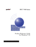
Parts of the Terminal
WAN Antenna (PDT 753x only)
Scan LED
LCD
Battery Charging LED
Communications LED
Thumb Rest
Scan Button
Power Key
Figure 1-1. Front View
Scan Window
Figure 1-2. Top View
1-4
Getting Started
Serial
Communications
Port
IrDA Port
Figure 1-3. Bottom View
Battery Latch
Figure 1-4. Back View
Accessories and Peripherals
CRD 7500
The CRD 7500 single- and four-slot cradles provide terminal storage and security, in-terminal
battery charging, spare battery pack charging, and RS-232 communications to a host
computer, or an external serial device such as a printer.
1-5
PDT 7500 Series Product Reference Guide for DOS
VCD 7500
The VCD 7500 vehicle cradle provides terminal storage and security, in-terminal and spare
battery pack charging, and communications to a Symbol Mobile Gateway (SMG).
The SMG (a PC with one or more communication ports and an API enabling
communications) allows a variety of peripherals to communicate with the terminal.
Holster
The holster provides convenient storage and protection for the terminal when not in use.
Handstrap
The handstrap provides a means of holding the terminal securely.
Battery Packs
Primary power for the PDT 7500 is provided by a 1400 mAh smart battery, which is a
rechargeable Lithium Ion (Li-Ion) battery pack. Backup power is provided by supercaps. For
information on installing and charging the battery pack, refer to Chapter 3, Cradle Setup and
Operation.
Cables
Cables for use with the PDT 7500 include:
!
!
RS-232 printer/host communications cable: a 3-foot coiled cable with squeeze lock
which includes a null modem and attaches the terminal to a DTE device.
RS-232 25-pin/9-pin modem cable: connects the terminal to a DCE device.
Power Supply
Power may also be supplied through an external AC adapter/ charging jack (p/n 50-14001005) as an alternative to the cradle.
Stylus
PDT 753X WAN Terminals
The PDT 753X is equipped with a CDPD or GSM WAN cellular radio and WAN antenna
that enables the terminal to operate in a wireless wide area network environment.
The optional stylus is available for performing pen functions.
1-6
Getting Started
PDT 754X Spectrum24 Radio Terminals
The PDT 754X is equipped with a Spectrum24 adapter card (Type II PC card connected to
an internally mounted antenna) that enables the terminal to operate in a Spectrum24
network.
The software required (interface, drivers, and configuration files) is described in the Series
7000 System Software Manual for DOS Applications and in the Spectrum24 NDK Product
Reference Guide. For information on configuration file edits to ensure proper operation of
the PDT 754X in a Spectrum24 environment, refer to the Spectrum24 Network Developer’s
Kit for DOS.
SDK
The Series 7000 Software Development Kit (SDK) for DOS contains all software and
documentation to assist you in developing applications to run on the PDT 7500.
You will need one or more application development environments (ADEs) from other
vendors to develop applications for the PDT 7500, for example Microsoft C/C++ 1.52 for
DOS.
Spectrum24 NDK
The Spectrum24 Network Development Kit (NDK) for DOS contains the network drivers,
samples, and documentation to assist you in developing network-aware applications to run
on the PDT 754X.
To develop applications for Spectrum24 for the PDT 754X, install both the PDT 7500 SDK
and the Spectrum24 NDK for DOS.
Third-Party Software
Other application development environments are available, such as Zetes MCL® Collection.
Contact your Symbol Representative for more information.
Before You Use the Terminal
Install and Charge Battery Pack
Prior to using the PDT 7500 for the first time, charge the Lithium-Ion battery pack. The
battery pack can be charged while in the terminal or charged separately in the cradle’s
charging slot. See Chapter 3, Cradle Setup and Operation, for instructions on installing the
cradle(s) and installing and charging the battery pack.
1-7
PDT 7500 Series Product Reference Guide for DOS
Note: It is possible to run the PDT 7500 from an external AC adapter/
charging jack while waiting for the battery pack to charge.
Configure the Terminal
Terminal configuration consists of loading the software and applications onto the terminal
and setting the terminal’s operating parameters. For more information on configuration see
the Terminal Configuration chapters later in this manual.
Run Setup
Run the Setup, described in Chapter 8, Terminal Configuration: Setup before using the
terminal for the first time.
1-8
Chapter 2 Software Installation
on the Development PC
Chapter Contents
Introduction . . . . . . . . . . . . . . . . . . . . . . . . . . . . . . . . . . . . . . . . . . . . . . . . . . . . . . . . . . . . . . . . . .
DOS . . . . . . . . . . . . . . . . . . . . . . . . . . . . . . . . . . . . . . . . . . . . . . . . . . . . . . . . . . . . . . . . . . . . . . . .
Spectrum24 NDK . . . . . . . . . . . . . . . . . . . . . . . . . . . . . . . . . . . . . . . . . . . . . . . . . . . . . . . . . . . . . .
Installing the SDK on the Development PC. . . . . . . . . . . . . . . . . . . . . . . . . . . . . . . . . . . . . . . . . . .
Installing Other Development Software . . . . . . . . . . . . . . . . . . . . . . . . . . . . . . . . . . . . . . . . . . . . .
2-3
2-3
2-4
2-4
2-4
2-1
PDT 7500 Series Product Reference Guide for DOS
2-2
Software Installation on the Development PC
Introduction
The Series 7000 Software Development Kit (SDK) for DOS and the Spectrum24 Network
Development Kit (NDK) for DOS are available for developing applications to run on the PDT
7500. These kits include:
!
!
Series 7000 Software Developer’s Kit (SDK) for DOS
" MS DOS 6.22
" Symbol-provided DOS Files (TSRs)
" PCMCIA Software
" Default Hex Image
" TCM Scripts
" Sample Code.
The Spectrum24 Network Developer’s Kit (NDK) for DOS, which includes:
" PDT 7500 Terminal Network Drivers for ODI
" TCM Scripts
" Sample Code
" Spectrum24 NDK for DOS Reference Guide.
DOS
The SDK installation program loads the required MS DOS 6.22 components on the
development PC used to create the hex files (via Terminal Configuration Manager) for
download to the terminal.
Note: The copy of MS DOS 6.22 supplied in the SDK is for use on the PDT
7500 ONLY. No license is included in the PDT 7500 SDK for using
MS DOS on the development PC; you must have your own valid MS
DOS license (preferably for MS DOS 6.22) for the development PC
to use the SDK.
The PDT 7500 is designed to run MS DOS 6.22, and all the programs provided by Symbol
for the PDT 7500 are based on MS DOS 6.22. If you use any other version of DOS in the
PDT 7500, Symbol cannot guarantee that all the terminal’s features will function properly.
2-3
PDT 7500 Series Product Reference Guide for DOS
Spectrum24 NDK
The NDK provides the drivers, utilities, sample code, and documentation to interface to the
Spectrum24 LAN.
The NDK also provides components of the Novell NetWare and LAN Workplace stacks for
use with the PDT 754X. To obtain the full set of components and documentation, contact
Novell.
Installing the SDK on the Development PC
The SDK is installed through Windows using Program Manager. The SDK uses a common
directory, C:\SYMSDK\SDK7000 by default unless you change it. To install the SDK on your
development PC:
1. On the development PC, insert the installation CD in the CD drive.
2. From the Program Manager’s File Menu, choose Run.
3. On the command line, type:
<drive>:SETUP
and press ENTER.
Note: To ensure the best operation of the SDK and NDK, do not change the
base path set up in the installation.
4. Follow the installation prompts that follow.
5. When the SDK installation is complete, follow these same instructions for the
Spectrum24 NDK, if necessary.
Installing Other Development Software
Developing applications for the PDT 7500 may require installing other development software
such as application development environments (e.g.Visual C++) on the development PC.
Follow the installation instructions provided with this software.
2-4
Chapter 3
Cradle Setup and Operation
Chapter Contents
Introduction . . . . . . . . . . . . . . . . . . . . . . . . . . . . . . . . . . . . . . . . . . . . . . . . . . . . . . . . . . . . . . . . . . 3-3
Parts of the CRD 7500 Single-Slot Cradle . . . . . . . . . . . . . . . . . . . . . . . . . . . . . . . . . . . . . . . . . . . 3-3
Parts of the CRD 7500 Four-Slot Cradle . . . . . . . . . . . . . . . . . . . . . . . . . . . . . . . . . . . . . . . . . . . . 3-4
Parts of the VCD 7500 Vehicle Cradle . . . . . . . . . . . . . . . . . . . . . . . . . . . . . . . . . . . . . . . . . . . . . . 3-5
Setting Up the CRD 7500 Single and Four-Slot Cradles . . . . . . . . . . . . . . . . . . . . . . . . . . . . . . . . . 3-6
Connecting Power . . . . . . . . . . . . . . . . . . . . . . . . . . . . . . . . . . . . . . . . . . . . . . . . . . . . . . . . . . 3-6
Connecting the RS-232 Cable to a Host Computer . . . . . . . . . . . . . . . . . . . . . . . . . . . . . . . . . 3-7
Setting Up the VCD 7500 Vehicle Cradle . . . . . . . . . . . . . . . . . . . . . . . . . . . . . . . . . . . . . . . . . . . . 3-7
Installing the VCD 7500 Cradle . . . . . . . . . . . . . . . . . . . . . . . . . . . . . . . . . . . . . . . . . . . . . . . 3-7
Connecting the VCD 7500 Vehicle Cradle a Host Computer . . . . . . . . . . . . . . . . . . . . . . . . . 3-9
Sending Data . . . . . . . . . . . . . . . . . . . . . . . . . . . . . . . . . . . . . . . . . . . . . . . . . . . . . . . . . . . . . 3-10
Cradle Self Test . . . . . . . . . . . . . . . . . . . . . . . . . . . . . . . . . . . . . . . . . . . . . . . . . . . . . . . . . . . . . . 3-10
Batteries . . . . . . . . . . . . . . . . . . . . . . . . . . . . . . . . . . . . . . . . . . . . . . . . . . . . . . . . . . . . . . . . . . . . 3-10
Battery Life . . . . . . . . . . . . . . . . . . . . . . . . . . . . . . . . . . . . . . . . . . . . . . . . . . . . . . . . . . . . . . 3-11
Backup Battery . . . . . . . . . . . . . . . . . . . . . . . . . . . . . . . . . . . . . . . . . . . . . . . . . . . . . . . . . . . 3-11
Installing a New or Recharged Battery . . . . . . . . . . . . . . . . . . . . . . . . . . . . . . . . . . . . . . . . . 3-11
Removing the Battery . . . . . . . . . . . . . . . . . . . . . . . . . . . . . . . . . . . . . . . . . . . . . . . . . . . . . . 3-12
Replacing the Battery in an Active Terminal . . . . . . . . . . . . . . . . . . . . . . . . . . . . . . . . . . . . . 3-13
Charging the Battery. . . . . . . . . . . . . . . . . . . . . . . . . . . . . . . . . . . . . . . . . . . . . . . . . . . . . . . . . . . 3-14
Charging the Battery in Cradle . . . . . . . . . . . . . . . . . . . . . . . . . . . . . . . . . . . . . . . . . . . . . . . 3-14
Charging the Battery Via Power Supply. . . . . . . . . . . . . . . . . . . . . . . . . . . . . . . . . . . . . . . . . 3-14
Charging the Spare Battery in the Cradle. . . . . . . . . . . . . . . . . . . . . . . . . . . . . . . . . . . . . . . . 3-15
3-1
PDT 7500 Series Product Reference Guide for DOS
3-2
Cradle Setup and Operation
Introduction
This chapter provides instructions for setting up and using the CRD 7500 single- and fourslot cradle and the VCD 7500 Vehicle Cradle.
Parts of the CRD 7500 Single-Slot Cradle
Spare Battery
Charging Slot
Terminal Slot
Spare Battery
Charge LED
Power Connector
Communication
(COM) LED
RS-232
Connection
Figure 3-1. Parts of the CRD 7500 Single-slot Cradle
3-3
PDT 7500 Series Product Reference Guide for DOS
Parts of the CRD 7500 Four-Slot Cradle
Spare Battery
Charging Slot
Spare Battery
Charging LED
Terminal Slot
Communication LED
Figure 3-2. CRD 7500 4-Slot Cradle
3-4
Cradle Setup and Operation
Parts of the VCD 7500 Vehicle Cradle
Terminal Release Buttons
Spare Battery
Charging Slot
Power Port
Power
Contacts
Serial Port
Communication LED
Spare Battery
Charge LED
Figure 3-3. VCD 7500 Vehicle Cradle
3-5
PDT 7500 Series Product Reference Guide for DOS
Setting Up the CRD 7500 Single and Four-Slot
Cradles
Setting up the single and four-slot cradle involves connecting power and connecting to a host
device.
Connecting Power
To connect power to the cradle:
1. Connect the power supply cable to the power connector on the back of the cradle.
2. Connect the power supply cable AC plug to a standard electrical outlet.
At power-up, the cradle’s COM LEDs lights yellow for 3 seconds. The COM LEDs blink
seven times.
Power Connector (Single-Slot Cradle)
Power Connector (Four-Slot Cradle)
Figure 3-4. Connecting Power to the Cradles
3-6
Cradle Setup and Operation
Connecting the RS-232 Cable to a Host Computer
1. Plug an RS-232 serial cable into the communication port located on the back of the
CRD 7500 Single-slot cradle, or on the right end of the four-slot cradle.
RS-232 Communication Port
(Single-Slot Cradle)
RS-232 Communication Port
(Four-slot Cradle)
Figure 3-5. RS-232 Communication Port
2. Connect the other end of the cable to the serial (COM) port of the host computer.
Setting Up the VCD 7500 Vehicle Cradle
This section provides the procedures for setting up the VCD 7500 Vehicle Cradle.
Installing the VCD 7500 Cradle
To install the vehicle cradle:
3-7
PDT 7500 Series Product Reference Guide for DOS
1. Prepare the mounting surface to accept four #8-32 studs in the pattern shown below.
1.188”
Holes for studs
1.5”
Note: Not to Scale
Figure 3-6. Installation Pattern: VCD 7500 Vehicle Cradle
1. Install the cradle on the mounting surface.
a. Position the cradle on the mounting surface.
b. Fasten using the appropriate hardware (#8-32 screws).
2. Connect the red and black power supply input leads to a fuse panel. A qualified
installer must perform the installation.
3-8
Cradle Setup and Operation
3. Insert the power connector from the power supply in the power port on the side of
the cradle.
Power Port
Figure 3-7. Power Connector: VCD 7500 Cradle
Connecting the VCD 7500 Vehicle Cradle a Host Computer
1. Plug a 9-pin serial cable into the communication port located next to the power port
on the side of the cradle.
Serial
Communication Port
Figure 3-8. Serial Connector: VCD 7500 Cradle
2. Connect the other end of the cable to the serial (COM) port of the host computer.
3-9
PDT 7500 Series Product Reference Guide for DOS
Sending Data
To begin communication:
1. Insert the terminal in the cradle.
2. As determined by your specific application, press the appropriate key(s) on the
terminal to initiate communication.
The cradle's Communications LED blinks yellow when communication begins.
Caution
Removing the terminal while the cradle’s Communications LED is on or
flashing yellow disrupts communication between the host and the terminal.
Cradle Self Test
On power up, the cradles perform a self-test which checks the RAM and ROM. The
Communications LED flashes during the self-test. The Communications LED on the cradle
reveals the status as follows:
Table 3-1. Cradle Power LED
Communications LED Condition
Status
Power up/Self-Test (7 flashes -> off)
No error in RAM or ROM
LED flashing (8 flashes/second)
RAM test failure
LED flashing slowly (4 flashes/second)
ROM (CRC on flash) failure
If the cradle fails self-test (RAM or ROM failure), power the cradle down and back up. If the
self-test fails again, call the Symbol Support Center for assistance.
Batteries
Primary power for the PDT 7500 is provided by a Lithium-Ion battery. The batteries operate
for 5 to 8 hours in typical operating environments, although battery life between charges
varies drastically depending on conditions, equipment options, and power demands.
3-10
Cradle Setup and Operation
Battery Life
To increase the Lithium battery life, use software controls to decrease power demands, such
as:
!
!
Turn off communication ports not used.
Turn off the backlight.
Backup Battery
Backup power is provided by supercaps. The backup batteries maintain RAM contents for a
maximum of 5 minutes while the Lithium-Ion battery is replaced.
Installing a New or Recharged Battery
Caution
To ensure proper terminal operation, use ONLY the Symbol Li-Ion battery
in the PDT 7500.
To install a new or recharged Li-Ion battery:
1. Hook the base of the new battery in the top of the battery compartment, then press
the into place.
Figure 3-9. Inserting the Battery
2. Slide the battery latch to secure the battery.
If the battery latch is not closed, do not operate the terminal, otherwise data may be lost.
3-11
PDT 7500 Series Product Reference Guide for DOS
Caution
Do not expose the battery to temperatures in excess of 140°F (60°C). Do not
disassemble, incinerate, or short circuit the battery.
Removing the Battery
To remove the Li-Ion battery from the terminal:
1. Suspend the terminal by pressing the PWR key.
2. Slide the battery release switch towards the top of the terminal until the lock releases.
Figure 3-10. Removing the Battery
3-12
Cradle Setup and Operation
3. Lift the battery up to the first detent, then slowly lift the battery out of the battery
compartment.
Figure 3-11. Lifting the Battery out of the Terminal
Replacing the Battery in an Active Terminal
If the terminal is active and power is supplied from an external source (wall cube adapter),
you can remove and replace the battery at any time.
If the terminal is running from battery power only, unlatching and/or removing the battery
causes the terminal to shut off power to the LCD display and to any PCMCIA cards that were
powered (i.e., modem or radio cards). The terminal may lose the program state and any data
stored in on-board RAM.
To avoid these problems, use the following procedure to replace the battery in an active
terminal running on battery power:
1. Suspend the PDT 7500 by pressing the Power key.
To ensure that the terminal is fully suspended and not timed out, press the Power key
again, wait for the display to come on, then press the Power key again to fully
suspend the terminal.
2. Press the battery eject latch to unlatch.
3. Lift the battery up to the first detent, then lift it slowly out of the battery
compartment.
4. Replace the battery and relatch.
3-13
PDT 7500 Series Product Reference Guide for DOS
Charging the Battery
Charge the battery fully before using the terminal. Lithium-Ion batteries charge fully in 2
hours or less in the terminal using the cradle. A spare battery can be charged in the cradle in
approximately 4 hours.To prevent overcharging, an internal monitoring circuit shuts off
power to the battery once it reaches full capacity.
Charging the Battery in Cradle
The cradle automatically recharges the battery when the terminal is properly inserted in the
cradle.
Note: To avoid loss of data, ensure that terminals placed in the cradle have
a battery installed.
To charge a battery in the terminal:
1. Verify that the cradle has power.
" For the CRD 7500 single- and four-slot cradle, connect the cradle’s power supply
jack to the power connector on the back of the cradle. Connect the power supply
plug to a standard electrical outlet.
" For the VCD 7500 vehicle cradle, connect the power supply to the power jack on
the side of the cradle. Verify that the power cable is connected to a power source.
2. Insert the terminal in the cradle. The terminal powers on and the terminal’s battery
charging LED turns yellow.
3. The terminal’s battery charging LED is yellow while charging. When the battery is
fully charged, the LED switches to solid green.
Leave the terminal in the cradle for 2 hours to recharge a fully discharged battery.
Charging the Battery Via Power Supply
The battery can be charged in the terminal using the power supply. The terminal can be used
while the battery is charging.
1. Plug the power supply connector in the round power supply port, located on the
back of the connector on the end of the serial cable.
2. Connect the power supply to the adapter cable.
3. Connect the other end of the adapter cable to a standard electrical outlet.
3-14
Cradle Setup and Operation
A fully discharged battery requires approximately 2 hours to recharge.
Charging the Spare Battery in the Cradle
To recharge a spare battery:
1. Verify that the cradle has power.
2. Insert the battery in the spare battery compartment charging slot.
Note: Spare batteries can only be inserted and removed when the terminal is
not in the VCD 7500 cradle.
3. Check the cradle LEDs to determine the spare battery’s charging status (refer to
Table 3-2).
a. If the Spare Battery Charge LED is yellow, the battery is still charging and should
not be used.
b. When the LED changes to green, the battery is fully charged. The Spare Battery
requires 4 hours to fully charge
4. To remove the battery from the charging slot, lift the battery out of the charging slot.
Table 3-2. Battery Charging LEDs
Condition
LED State
Battery Charging LED
Off
Spare battery absent, no charge power, or outside temperature
range required for charging battery.
Steady yellow
Spare battery is charging.
Steady green
Spare battery is charged.
Flashing yellow
Abnormal battery.
Communications LED
Off
Terminal is not trying to communicate.
On (yellow)
Terminal is able to send and receive data.
3-15
PDT 7500 Series Product Reference Guide for DOS
3-16
Chapter 4
Operating the Terminal
Chapter Contents
Introduction . . . . . . . . . . . . . . . . . . . . . . . . . . . . . . . . . . . . . . . . . . . . . . . . . . . . . . . . . . . . . . . . . . 4-3
Powering on the PDT 7500 . . . . . . . . . . . . . . . . . . . . . . . . . . . . . . . . . . . . . . . . . . . . . . . . . . . . . . 4-3
Booting the Terminal . . . . . . . . . . . . . . . . . . . . . . . . . . . . . . . . . . . . . . . . . . . . . . . . . . . . . . . . . . . 4-4
Suspending and Resuming Operation . . . . . . . . . . . . . . . . . . . . . . . . . . . . . . . . . . . . . . . . . . . . . . . 4-4
Adjusting the Display and Volume . . . . . . . . . . . . . . . . . . . . . . . . . . . . . . . . . . . . . . . . . . . . . . . . . 4-5
Scanning . . . . . . . . . . . . . . . . . . . . . . . . . . . . . . . . . . . . . . . . . . . . . . . . . . . . . . . . . . . . . . . . . . . . . 4-6
Using the Scanner . . . . . . . . . . . . . . . . . . . . . . . . . . . . . . . . . . . . . . . . . . . . . . . . . . . . . . . . . . 4-6
Scanning Considerations . . . . . . . . . . . . . . . . . . . . . . . . . . . . . . . . . . . . . . . . . . . . . . . . . . . . . 4-7
Smart Raster Capability . . . . . . . . . . . . . . . . . . . . . . . . . . . . . . . . . . . . . . . . . . . . . . . . . . . . . 4-8
Scanning Mode Options . . . . . . . . . . . . . . . . . . . . . . . . . . . . . . . . . . . . . . . . . . . . . . . . . . . . . 4-9
Scanning PDF417 Bar Codes . . . . . . . . . . . . . . . . . . . . . . . . . . . . . . . . . . . . . . . . . . . . . . . . . . 4-9
Scanning (Imager). . . . . . . . . . . . . . . . . . . . . . . . . . . . . . . . . . . . . . . . . . . . . . . . . . . . . . . . . . . . . 4-12
Scanning . . . . . . . . . . . . . . . . . . . . . . . . . . . . . . . . . . . . . . . . . . . . . . . . . . . . . . . . . . . . . . . . 4-12
Operational Modes . . . . . . . . . . . . . . . . . . . . . . . . . . . . . . . . . . . . . . . . . . . . . . . . . . . . . . . . 4-13
Aiming the Imager. . . . . . . . . . . . . . . . . . . . . . . . . . . . . . . . . . . . . . . . . . . . . . . . . . . . . . . . . 4-13
Performing Communications . . . . . . . . . . . . . . . . . . . . . . . . . . . . . . . . . . . . . . . . . . . . . . . . . . . . 4-15
Communicating via RS-232 Cable. . . . . . . . . . . . . . . . . . . . . . . . . . . . . . . . . . . . . . . . . . . . . 4-15
Communicating via Cradle . . . . . . . . . . . . . . . . . . . . . . . . . . . . . . . . . . . . . . . . . . . . . . . . . . 4-15
Spectrum24 Communications . . . . . . . . . . . . . . . . . . . . . . . . . . . . . . . . . . . . . . . . . . . . . . . . 4-16
4-1
PDT 7500 Series Product Reference Guide for DOS
Introduction
This chapter describes how to operate a PDT 7500 terminal, including:
powering the PDT 7500
booting the terminal
!
adjusting the display’s contrast
!
using the keyboard
!
entering data through the integrated scanner
!
communicating.
!
Once the terminal is initialized and power is applied via a fully charged battery pack or a
power source, it is ready for operation.
!
Powering on the PDT 7500
Because the terminal is battery powered, it is important to save power whenever possible. You
can minimize power loss and increase battery life by turning the terminal off when data is not
being entered.
While the terminal’s processor and display are off, programs or data in the system's memory
are retained. Before the terminal powers up, it checks the batteries for enough power to
ensure reliable operation and data storage. Power-up restores the display, and processing
continues from where it was before power-down.
4-2
Operating the Terminal
To power on the PDT 7500:
1. make sure a fully charged battery is installed in the terminal.
2. press the power key
.
To suspend the PDT 7500’s operation, press the power key again.
Booting the Terminal
The warm boot process is similar to pressing the <Ctrl+Alt+Del> keys on a PC. To perform
a warm boot, press and hold the power key for 6 seconds, then release.
Cold booting the terminal generates a system reset, the same as a power-on boot on a
standard PC. To cold boot the terminal, hold down the Power key for 15 seconds or for the
amount of time set in Setup. See Chapter 8, Terminal Configuration: Setup for more
information on Setup.
Suspending and Resuming Operation
To suspend or resume operation, press the PWR key
on the PDT 7500. The terminal can
also resume operation from various wakeup sources (if enabled through the application). The
wakeup sources available on the PDT 7500 are listed in Table 4-1.
Note: The default for enabling/disabling these wakeup sources depends on
how the terminal is suspended (manual suspend using the PWR key
vs. automatic suspend via timeout). An application can also control
the source of a terminal wakeup, overriding the defaults.
Table 4-1. PDT 7500 Wakeup Sources
Source
Manual Default
(PWR key)
Automatic Default
(timeout)
PWR key and touch panel power area
enabled
enabled
AC adapter connect
disabled
enabled
Cradle insert/remove
disabled
enabled
Battery insert
disabled
enabled
4-3
PDT 7500 Series Product Reference Guide for DOS
Table 4-1. PDT 7500 Wakeup Sources (Continued)
Source
Manual Default
(PWR key)
Automatic Default
(timeout)
Scan trigger(s)
disabled
enabled
keyboard (any key)
disabled
enabled
Touch pad (any touch)
disabled
enabled
Alarm timer
disabled
enabled
PCMCIA Slot (0/1)
disabled
enabled
COM ring (1/2)
disabled
enabled
COM Rx Data (1/2)
disabled
enabled
Terminal operation can be suspended in four ways:
!
!
!
!
Manual suspension
" the operator presses the PWR key. Refer to Table 4-1 for the default values.
Automatic suspension
" the terminal times out because of no operator activity. Refer to Table 4-1 for the
default values.
Program dependent suspension
" the application requests a suspend via an API call
" the application sets a wakeup
Critical suspension
" the battery pack is removed or is very low
" PWR key is required to resume.
Adjusting the Display and Volume
The terminal’s backlight illuminates the display in dimly lit areas.
Note: Use of backlighting can significantly reduce battery life.
To turn the backlight on or off, press the blue FUNC key, then press the LAMP key.
4-4
Operating the Terminal
There are two ways to adjust the display’s contrast and backlight, and the speaker volume on
the PDT 7500:
!
!
!
establish the initial values using the setup utility (refer to Chapter 8, Terminal
Configuration: Setup).
Contrast can be adjusting be pressing the FUNC key, then either the light or dark key.
adjust the values through an application, if allowed by the software.
Scanning
The PDT 7500 offers two scanning capability options:
!
!
1-D standard
PDF417 scanning.
Note: The scanning application and scanner driver must be loaded on the
terminal to perform scanning.
Using the Scanner
To use the integrated laser scanner:
1. Verify that the system is on (the display is active).
2. Ensure that a scanning-capable application is loaded and running, and that the
application is in a state to allow scanning.
3. Aim the scan window at the bar code.
4. Adjust the aim so that the thin, red laser beam covers the entire length of the bar
code.
:URQJ
5LJKW
Optimal scanning distance varies with bar code density and scanner optics, but most
combinations work within 4 to 10 inches. Generally:
" Hold the scanner farther away for larger symbols.
" Move the scanner closer for symbols with bars that are close together.
4-5
PDT 7500 Series Product Reference Guide for DOS
5. Press the scan button.
6. If the decode is successful, the LED turns from yellow to green. The terminal may
also beep.
Note: The procedure for your scanner may differ from the one listed above.
Scanner operation depends on the application.
Scanning Considerations
Usually, scanning is a simple matter of aim, scan, and decode, and a few quick trial efforts
master it. However, two important considerations can optimize any scanning technique —
range and angle.
Range
Any scanning device decodes well over a particular working range — minimum and
maximum distances from the bar code. This range varies according to bar code density and
scanning device optics.
Scanning within range brings quick and constant decodes; scanning too close or too far away
prevents decodes. So you need to find the right working range for the bar codes you are
scanning. However, the situation is complicated by the availability of multiple integrated
scanning modules, some with specialized capabilities such as long range and 2-D decode
capability. The best way to specify appropriate working range per bar code density is through
a chart called a decode zone for each scan module. A decode zone simply plots working range
as a function of minimum element widths of bar code symbols.
Decode zones for integrated scan elements available on the PDT 7500 are provided in
Appendix A, Specifications.
Angle
Scanning angle is important for promoting quick decodes. When laser beams reflect directly
back into the scanner from the bar code, this specular reflection can “blind” the scanner.
To avoid this, scan the bar code so that the beam does not bounce directly back. But don’t
scan at too sharp an angle; the scanner needs to collect scattered reflections from the scan to
make a successful decode. Practice quickly shows what tolerances to work within.
4-6
Operating the Terminal
Note: Contact the Symbol Support Center if you have chronic difficulties
scanning. Decoding of properly printed bar codes should be quick and
effortless.
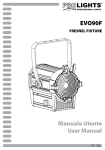
Smart Raster Capability
All integrated 1-D/PDF417 scan elements may be programmed for “Smart Raster” capability,
which causes the scanner to emit a raster pattern dynamically optimized to the particular
PDF417 bar code’s shape. To increase scanning efficiency and optimize decode time, the
scanner determines the geometry of the bar code and opens at a rate and size optimal for
decoding that bar code.
In normal Smart Raster operation, a trigger pull causes a slab raster pattern to appear. If the
target is a 1-D bar code, the slab raster decodes the bar code. If the target bar code is PDF417,
the scanning patterns open up to a full, optimized raster pattern as soon as the scanner is
properly aligned over the bar code (Figure 4-1).
$LPLQJ³'RW´3DWWHUQ
$LPLQJ³6ODE´5DVWHU3DWWHUQ
Y-Axis
Y-Axis
2SHQ5DVWHU3DWWHUQ
+RUL]RQWDO'LVSODFHPHQW;$[LV
Figure 4-1. 1-D/PDF417 Scan Element Aiming and Scanning Patterns
4-7
PDT 7500 Series Product Reference Guide for DOS
For best operation in Smart Raster mode, keep the scan pattern as parallel to the symbol’s
rows as possible, keep the scanner as still as possible, and hold the scanner at an angle which
does not give specular reflection (refer to Angle on page 4-6). The symbol should also be in
good condition.
Scanning Mode Options
There are three scanning options: aiming with a dot pattern, scanning with a slab raster
pattern, or always raster.
Aiming Dot Option
A trigger pull creates the single dot aiming pattern, which lasts for a fixed interval. This dot
easily can be seen in outdoor or high ambient light environments. A slab raster pattern or an
open raster pattern appears next, depending on the programmed scanning option. There are
two programmable timeout periods for this option — normal and extended.
Slab Raster Aiming Option
A trigger pull creates the slab raster pattern. If the target is a 1-D bar code, the slab pattern
decodes the bar code. If the target bar code is PDF417, the pattern opens up to an optimized
raster pattern as soon as the scanner is properly aligned over the bar code.
Always Raster Option
When programmed to this option, the PDF417 scan element directly opens to a full raster
pattern whenever the trigger is pulled.
Scanning PDF417 Bar Codes
Make sure the terminal is programmed for a slab raster aiming pattern and Smart Raster
mode.
1. Aim the scanner at the symbol. Try to keep the nose of the scanner parallel with the
symbol’s rows.
2. Make sure the symbol you want to scan is within the scanning range; refer to the 1D/PDF417 decode zones. Then pull the trigger.
The scan pattern first covers the symbol horizontally (Figure 4-2). Make sure the
4-8
Operating the Terminal
scan pattern extends at least three-quarters of an inch beyond the edges of the bar
code.
Figure 4-2. Slab Raster Pattern on a PDF417 Bar Code
3. If the pattern is parallel to the symbol’s rows, the pattern spreads vertically to cover
the symbol (Figure 4-3). If the pattern does not cover the top and bottom of the
symbol, pull the scanner back until it does.
3/4”
3/4”
Figure 4-3. Scanning Pattern Spreading Over PDF417 Bar Code
4-9
PDT 7500 Series Product Reference Guide for DOS
The scanner has successfully decoded the symbol when the green LED lights and you hear a
short, high tone beep.
Scan the Entire Bar Code Symbol
!
!
!
!
The larger the symbol, the farther away you should hold the scanner to permit the
raster pattern to cover the symbol (but not more than 8 inches). See the 1-D/PDF417
Scan Element Decode Zones.
Hold the scanner close for denser symbols (not less than 2 inches).
In all cases, make sure the scan pattern extends at least 3/4 inch beyond each edge of
the bar code (Figure 4-4).
The PDF417 bar code symbol has multiple rows, but the raster pattern also has
multiple scanning rows. For this reason, do three basic things as you scan:
" Center the aiming pattern on the bar code, as illustrated before.
" Keep the pattern in the same horizontal plane as the bar code.
3/4”
3/4”
Figure 4-4. Orienting Scanning Pattern On PDF417 Bar Code
" If the vertical scan pattern is not high enough to cover a “tall” PDF417 symbol,
move the scanner slowly down toward the bottom of the symbol, keeping the
beam horizontal to the rows, and then slowly back upward toward the top
(Figure 4-5).
4-10
Operating the Terminal
Figure 4-5. Moving Scan Pattern Upward and Downward on “Tall” PDF Symbol
!
The scan beam does not have to be perfectly parallel with the top and bottom of the
symbol (up to a 4o tilt will work).
Scanning (Imager)
The Imager has the following features:
!
!
!
omnidirectional reading of a variety of bar code symbologies, including the most
popular linear, postal, PDF417, and 2D matrix code types.
the ability to capture and download images to a host for a variety of imaging
applications.
advanced intuitive laser aiming for easy point-and-shoot operation.
Scanning
The Imager uses digital camera technology to take a digital picture of a bar code, stores the
resulting image in its memory, and executes state-of-the-art software decoding algorithms to
extract the data from the image. A typical bar code decoding process is as follows:
1.
2.
3.
4.
The user aims the Imager and presses the scan button.
The red laser aiming pattern turns on to assist in aiming the Imager.
If necessary, the Imager turns on its red LEDs to illuminate the target bar code.
The Imager takes a digital picture (image) of the bar code and stores it in memory
for decoding.
4-11
PDT 7500 Series Product Reference Guide for DOS
5. A decode beep occurs and the Imager transmits the bar code data to the host.
6. The user releases the scan button.
This process usually occurs instantaneously. Steps 2 - 4 are repeated on poor or difficult bar
codes as long as the scan button remains pressed.
Operational Modes
The Imager has two modes of operation: Decode Mode and Image Capture Mode, activated
by pressing the scan button.
Decode zones for the Imager on the PDT 7500 are provided in Appendix A, Specifications
Decode Mode
In this default mode, upon pressing the scan button, the Imager attempts to locate and decode
enabled bar codes within its field of view. The Imager remains in this mode as long as the scan
button is pressed, or until a bar code is decoded.
Image Capture Mode
This mode can be entered via the Scanner API. The Imager turns on its laser aiming pattern
to highlight the area to be captured in the image. The scan button press instructs the Imager
to capture a high quality image and transmit it to the host. A short time may pass (less than
2 seconds) between when the scan button is pressed, and the image is captured as the Imager
adjusts to the lighting conditions. Hold the terminal steady until the image is captured
(denoted by a single beep).
Aiming the Imager
The Imager projects a laser aiming pattern (shown below) similar to those used on cameras.
The aiming pattern allows you to position the bar code or object within the field of view.
Figure 4-6. Laser Aiming Pattern
To scan a symbol with the Imager:
4-12
Operating the Terminal
1. Center the symbol in any orientation within the aiming pattern. Be sure the entire
symbol is within the rectangular area formed by the brackets in the aiming pattern.
Linear bar code
PDF417 symbol
Symbol
View Finder
(Aiming Pattern)
Figure 4-7. Centering Symbol in Aiming Pattern
The Imager can also read a bar code presented within the aiming pattern but not
centered, such as the figure below on the left. The figure on the right, however, can
not be decoded.
Figure 4-8. Acceptable and Incorrect Aiming
2. The aiming pattern is smaller when the Imager is closer to the symbol and larger
when it is farther from the symbol. Scan symbols with smaller bars or elements (mil
size) closer to the unit, and those with larger bars or elements (mil size) farther from
the unit.
3. Hold the terminal between two and nine inches (depending on symbol density) from
the symbol, centering the aiming pattern cross hairs on the symbol.
4. Press and hold the scan button until the terminal beeps, indicating the bar code is
successfully decoded.
4-13
PDT 7500 Series Product Reference Guide for DOS
Performing Communications
The PDT 7500 terminal communicates with a host either through an RS -232
communications cable, or placed in a CRD 7500 or VCD 7500 cradle. PDT 7540 terminals
communicate with a host computer or other wireless units over the Spectrum24 wireless LAN
network.
Communicating via RS-232 Cable
To perform direct communications using an RS-232 cable, connect the terminal to the host
via the communications port:
1. Suspend (temporarily power the terminal off) the terminal by pressing the PWR key.
2. Connect the communication cable’s connector to the adapter cable’s connector.
3. Plug the adapter’s subminiature connector in the communications port on the
bottom of the terminal.
4. Plug the other connector on the communication cable to the host’s COMM port.
5. Start the communications program.
Communicating via Cradle
The cradle enables communications between the PDT 7500 and a computer, printer, modem,
or other peripheral device.
CRD 7500 Four-Slot Cradle and VCD 7500 Vehicle Cradle
To begin communication:
1. Make sure all power and serial connections are secure.
2. Insert the terminal in the cradle.
3. As determined by your specific application, press the appropriate key(s) on the
terminal to initiate communication.
The cradle's Communications LED blinks yellow when communication begins.
Caution
Removing the terminal while the cradle’s Communications LED is on or
flashing disrupts communication between the host and the terminal.
4-14
Operating the Terminal
Note: The Communications LED does not light if cradle mode is not
enabled or if the terminal is not inserted in a cradle.
Spectrum24 Communications
For information on changing subnets (changing ESS_ID) or performing network diagnostics
on the terminal or general Spectrum24 configuration, refer to the Spectrum24 NDK for DOS
Reference Guide, provided with the NDK.
For general information on the Spectrum24 wireless LAN network, refer to the Spectrum24
Ethernet Access Point User Guide, Spectrum24 Wireless LAN PC Card User Guide, and the
Spectrum24 Wireless LAN ISA Adapter User’s Guide.
4-15
PDT 7500 Series Product Reference Guide for DOS
4-16
Chapter 5 Terminal Configuration:
Edit the Configuration Files
Chapter Contents
Setup/Edit DOS Configuration Files . . . . . . . . . . . . . . . . . . . . . . . . . . . . . . . . . . . . . . . . . . . . . . . . 5-3
CONFIG.SYS . . . . . . . . . . . . . . . . . . . . . . . . . . . . . . . . . . . . . . . . . . . . . . . . . . . . . . . . . . . . . 5-3
AUTOEXEC.BAT . . . . . . . . . . . . . . . . . . . . . . . . . . . . . . . . . . . . . . . . . . . . . . . . . . . . . . . . . . 5-8
Symbol-Supplied TSRs and Device Drivers . . . . . . . . . . . . . . . . . . . . . . . . . . . . . . . . . . . . . . . 5-8
Symbol-Supplied Utilities. . . . . . . . . . . . . . . . . . . . . . . . . . . . . . . . . . . . . . . . . . . . . . . . . . . . 5-10
Symbol-Supplied Network Configuration Files . . . . . . . . . . . . . . . . . . . . . . . . . . . . . . . . . . . 5-12
5-1
PDT 7500 Series Product Reference Guide for DOS
5-2
Terminal Configuration: Edit the Configuration Files
Setup/Edit DOS Configuration Files
This section details the recommended edits of DOS system files. For more information on
editing the DOS system files covered in this section, please refer to the Microsoft® MS-DOS
User’s Guide.
Note: See the Spectrum24 NDK for DOS Reference Guide for
CONFIG.SYS and AUTOEXEC.BAT file edits for use in the
Spectrum24 environment.
CONFIG.SYS
HIMEM.SYS Device Driver
This driver provides access to the terminal’s extended memory (RAM beyond the first 1 MB).
It provides services for managing the High Memory Area (HMA), which is the first 64K of
extended memory, and an Extended Memory Specification (XMS) API for managing the
remainder of extended memory.
Various uses of extended memory include:
!
!
!
!
Loading DOS high (see DOS Settings: DOS = HIGH)
Using Upper Memory Blocks (UMBs; see EMM386.EXE)
Using Expanded Memory (EMS; see EMM386.EXE)
Using DOS Extenders.
Note: This driver must be loaded in CONFIG.SYS to allow use of extended
memory. Most configurations created for the PDT 7500 should
include this driver.
Recommended usage in CONFIG.SYS is:
DEVICE=HIGHMEM.SYS/TESTMEM:OFF
The /TESTOFF:OFF option skips the memory test and speeds up the boot process.
5-3
PDT 7500 Series Product Reference Guide for DOS
EMM386.EXE Device Driver
This driver provides alternate access to extended memory. This driver requires that
HIMEM.SYS be loaded first and uses the XMS API provided by HIMEM.SYS to further
manage extended memory.
Extended memory is “translated” into other types of memory such as Upper Memory Blocks
(UMBs) and Expanded Memory (EMS). UMBs allow additional RAM memory to be located
in unused areas of the first 1 MB of the address space. TSRs and drivers can be loaded into
UMBs via the LOADHIGH and DEVICEHIGH commands, leaving additional Transient
Program Area (TPA) available for application use. Expanded memory uses a 64K page frame
within the first 1MB of the address space to allow RAM to be mapped in 16K pages via the
EMS (LIM 4.0) API.
Note: Include this driver in the PDT 7500 configuration ONLY if UMBs or
EMS are required.
Recommended command line switches include:
1. If EMS memory is not required, add the following line to allocate all unused Upper
Memory Blocks for DEVICEHIGH and LOADHIGH commands:
DEVICE=EMM386.EXE NOEMS X=B000-BFFF
CONFIG.SYS DOS Settings
• BREAK = [ ON | OFF ]
Controls whether or not extended CTRL+C checking is enabled. Since this feature introduces
additional overhead and is useful only when a keyboard is attached, it should be disabled
under most circumstances. Off is the default setting; hence this command need not be used
unless this feature is being enabled.
• BUFFERS = n[,m] 1≤n≤99 0≤m≤8
Specifies the number of disk buffers to be allocated for use by DOS. The default value for the
PDT 7500 is n=15 and m=0. Many applications and environments request a larger setting.
Windows, for example, recommends a setting of n=20 and m=0. Using too large a value
wastes memory and using too small a value can reduce performance. Unless there is a specific
requirement, we recommend using the n=20 and m=0 settings.
5-4
Terminal Configuration: Edit the Configuration Files
• COUNTRY = XXX[,YYY]
Specifies the country-specific settings. The default is U.S. This command is required only for
a different country setting.
• DEVICE = driver.ext
DEVICEHIGH = driver.ext
This command causes a device driver to be loaded either low (into TPA) or high (into UMBs).
Drivers cannot be loaded high until both HIMEM.SYS and EMM386.EXE have been loaded
low and DOS=UMB has been specified.
• DOS = [HIGH | UMB ]
This command allows DOS to load information into the HMA (DOS = HIGH), increasing
the amount of TPA available for applications. This command also enables loading TSRs and
drivers into UMBs via the LOADHIGH and DEVICEHIGH commands (DOS=UMB).
Note: DOS = HIGH can only be used if HIMEM.SYS is loaded.
DOS = UMB can be used only if both HIMEM.SYS and
EMM386.EXE are loaded.
• FILES = n 8≤n≤255
Controls the number of files that DOS can open at once. The larger this number, the more
memory DOS allocates for file handles. The default is 8, which is generally inadequate for
most applications and environments. Allocating too many files wastes memory; allocating
too few files may cause an application or environment to fail if it attempts to open too many
files. Unless there is a specific requirement for more files, we recommend using a value of
n=20.
• INSTALL = file.ext
This command loads a TSR from CONFIG.SYS. This command can be used to load TSRs
(low only) that go along with drivers (as a convenience). Note that DOS does not load the
TSRs until the end of CONFIG.SYS (as opposed to where they appear). If you use your
application as a shell (see SHELL=), you can use this command to load TSRs prior to
execution of the application as the shell.
• LASTDRIVE = x
Specifies the number of disk drives managed by DOS. This command is necessary only if the
number of drive letters managed by DOS must be increased. DOS automatically allocates C:
and possibly D:, E: and F:, if additional FLASH disk(s) are present.
5-5
PDT 7500 Series Product Reference Guide for DOS
The RAM disk driver and DRVSPACE are device drivers that allocate new drive letters
beyond those automatically allocated by DOS. LASTDRIVE only adds new drive letters (to
be managed by DOS) if the drive letter specified is greater than the last drive letter
automatically allocated by DOS or by device drivers such as RAM Disk and/or DRVSPACE.
One common use of this command is to reserve one or more drive letters for use by the DOS
SUBST command, in addition to the drives needed for RAM Disk and DRVSPACE.
For example, if DOS is managing drives A-F, set LASTDRIVE=G.
For Spectrum24 use with Novell Netware and LAN Workplace TCP/IP stack, LASTDRIVE=
must be set to Z.
• NUMLOCK = [ON | OFF ]
This command sets the state of the numeric lock key on the keyboard on boot up.
• SET
This command sets environment variables in CONFIG.SYS instead of in AUTOEXEC.BAT.
Note: Environment variables are set in CONFIG.SYS only at the end of
CONFIG.SYS, regardless of where the SET command occurs.
Consequently, these settings cannot be used by device drivers, and this
command is generally only used if environment variables are required
by TSRs loaded via the INSTALL= command, or if the application is
being used as a command shell (e.g., turn-key application).
• SET COMSPEC=
This command specifies the drive and path where the shell can be found. Use this command
only if the SHELL= command is used to select a program other than COMMAND.COM as
the shell, or if the shell is located in a directory other than the root directory of the boot drive.
• SHELL = file.ext
This command specifies the command shell to be used. The default command shell is
COMMAND.COM from the boot drive’s root directory.
Reasons for using this command include:
" To increase the size of the environment table when running COMMAND.COM
as the shell.
5-6
Terminal Configuration: Edit the Configuration Files
The recommended command line for this is:
SHELL=C:\COMMAND.COM/P/E:1024
For additional information, consult the MS-DOS User’s Guide.
" To run (and store) COMMAND.COM in a directory other than the root
directory (see also SET COMSPEC= above)
Note: TCM automatically puts COMMAND.COM in the root directory of
a FLASH disk marked as bootable, so this should seldom be needed.
" To use an application other than COMMAND.COM as the shell.
• STACKS = n, s0≤n≤64, 32≤s≤512
This command controls the number and size of the DOS stacks used to service hardware
interrupts. Unless there is a specific requirement otherwise, we recommend using a value of
n=9 and s=256 to save memory.
MS-DOS Device Drivers
• ANSI.SYS
This driver provides text mode display attribute support for applications that desire ANSI
terminal command set portability.
• DISPLAY.SYS
This driver allows internationalization of the text mode character set.
• RAMDRIVE.SYS
This driver creates a simulated “disk” using TPA, EMS, or XMS RAM.
• SETVER.EXE
This driver reports different version numbers for use with DOS-version-specific software
programs. Consult the MS-DOS User’s Manual for more information.
• SMARTDRV.EXE
This driver caches access to disk drives, thus increasing disk access speed. Due to the solid
state nature of the “disks” available on the PDT 7500, this driver may be of limited use.
5-7
PDT 7500 Series Product Reference Guide for DOS
AUTOEXEC.BAT
Note: AUTOEXEC.BAT is processed by COMMAND.COM and has no
meaning if another program is used as a shell (see the section SHELL=
above).
DOS Settings
• ECHO [ON | OFF | TEXT ]
This command (which is commonly used in batch files, especially AUTOEXEC.BAT) displays
a text string (the TEXT option), or enables/disables the echoing of commands in the batch
file as it is executed. When a batch file is used to execute a program, it gives a more
“transparent” look if the commands which “set up” the applications’s execution are hidden.
To prevent the ECHO OFF command from itself echoing, precede it with an @ sign (e.g.,
@ECHO OFF).
• MODE
This command sets up and/or configures various drivers. Refer to the MS-DOS User’s
Manual for more information.
• PATH
This command sets the path(s) used to find executable programs.
• PROMPT
This command modifies the DOS COMMAND.COM shell prompt.
• SET
This command sets environment variables. This is normally used to set up environment
variables required by TSRs or applications/environments.
Symbol-Supplied TSRs and Device Drivers
Symbol has provided the following device drivers and TSRs for use with the PDT 7500. For
information on loading the TSRs device drivers, and on the APIs supported by each device
driver or TSR, refer to the Series 7000 System Software Manual for DOS p/n 70-36860-XX.
• POWER7XT.EXE
The Power Management Driver TSR API provides operating-system level power
management. Use this TSR instead of the POWER.EXE TSR supplied with MS-DOS. While
5-8
Terminal Configuration: Edit the Configuration Files
POWER.EXE can be used on the PDT 7500, it cannot be used in conjunction with
POWER7XT.EXE, and does not provide as efficient a power management.
POWER7XT.EXE requires that XBIOS7XT.EXE is loaded first and will not load unless one
of these two files is present. When used on the development PC with XBIOS7XT.EXE, this
TSR can be used for testing power management functionality of an application on the
development PC.
• XBIOS7XT.EXE
This TSR provides extended BIOS-level functionality specific to Series 7000 features.
XBIOS7XT.EXE can be loaded on the development PC or the Series 7000 terminal for use in
testing and debugging Series 7000 applications on the development PC.
• MOUSE7XT.EXE
The Mouse TSR API provides Microsoft Mouse-compatible use to support the use of the pen
and digitizer as a mouse. Mouse-aware applications can use this TSR to provide mouse
emulation.
• SCN1DQST.EXE and SCN2DQST.EXE
The DOS Scanner API provides one- and two-dimensional bar code scanning support and
supplies an API for controlling scanning from an application. These TSRs require the
presence of POWER7XT.EXE and XBIOS7XT.EXE to load. Additionally, these drivers
require the presence of Series 7000-specific hardware, and cannot be loaded on the
development PC (even if XBIOS7XT.EXE is loaded).
• WARMBEEP.EXE
This application, when loaded on the terminal, causes an audible beep to sound when the
defined warm boot time has expired. This is to assist the user in understanding the time when
a warm boot occurs. See the Series 7000 System Software Manual for DOS Applications for
more information.
CardSoft
• CS_APM
A TSR that must be loaded to utilize advanced power management functions for CardSoft.
This TSR can also be installed in CONFIG.SYS with the CardSoft drivers using the Install
command.
Note: Do NOT load CS_APM in CONFIG.SYS and AUTOEXEC.BAT.
5-9
PDT 7500 Series Product Reference Guide for DOS
• Spectrum24 ODI
The Spectrum24 ODI drivers provided by Symbol consist of Novell’s Link Support Layer
(LSL), Novell’s TCP/IP, and Symbol’s Multiple Link Interface Driver (MLID) layers. These
executables are part of the Spectrum24 NDK for DOS.
• LSL.COM
The LSL manages communications between TCP/IP protocol stack and SL8ODIOS. This
layer is a component of the Novell Open DataLink Interface (ODI) driver specification.
• TCPIP.EXE
This is Novell’s TCP/IP Multiple Protocol Interface (MPI). It supports the Berkeley socket
APIs. This layer is a component of the ODI driver specification.
• SL8ODIOS.COM
This is the Spectrum24 MLID Network Driver. The MLID layer controls a specific network
interface and works below the LSL. The MLID manages the transmission and reception of
packets to and from a physical or logical network interface. This layer is a component of the
ODI driver specification.
Symbol-Supplied Utilities
• PDTSET.EXE
A utility that allows various system settings to be altered from AUTOEXEC.BAT. This utility
is provided with the source code and an abstract explaining its use in the DOSSAMP\PDTSET
directory.
• PDTCHECK.EXE
A utility that allows various system conditions to be tested (e.g., trigger, pen, drive letter
presence, display size, etc.). This utility is provided with the source code and an abstract
explaining its use in the DOSSAMP\PPTCHECK directory.
CardSoft is supplied with the Symbol Series 7000 SDK as a series of drivers which are loaded
in CONFIG.SYS:
ATADRV.EXE
5-10
'(9,&(+,*+ DWDGUYH[H
Terminal Configuration: Edit the Configuration Files
CS.EXE
'(9,&(+,*+ FVH[H
CSALLOC.EXE
'(9,&(+,*+ FVDOORFLQL
SS365SL.EXE
'(9,&(+,*+ VVVOH[H
CARDID.EXE
'(9,&( FDUGLGH[H
• CSALLOC.INI
This file is used by the CSALLOC.EXE driver to allocate memory, I/O, and interrupt
resources to PCMCIA cards. Much of the upper memory area is used by the BIOS. This
memory must be excluded from use by lines in the CSALLOC.INI file.
The default CSALLOC.INI file contains the following memory settings:
RIO=2F8-2FF,370-377,3E8-3FF,100-1FFF
MEMEXCLUDE=C000-CFFF,D000-DFFF,E000-EFFF
Generally, these lines are constant and should never be changed by the user.
The PDT 7500 has IRQ lines dedicated for internal system use, others are available for
PCMCIA I/O cards. IRQ 11 and 15 are available to PCMCIA I/O cards; IRQ 3 and 4,
although allocated for internal communication ports, can be used by PCMCIA modems when
the internal communication ports (COM1 and COM2) are not active.
To allow use of an I/O card that requires an IRQ line in a PCMCIA slot, the default
CSALLOC.INI contains the following lines:
IRQEXCLUDE=0-2,5-9,C-E
IRQINCLUDE=A-B,F
This restricts the I/O cards to IRQ lines 10, 11, and 15.
In addition to the IRQ lines discussed above, modem cards may also use IRQ lines 3 and 4
for COM3 and COM4, respectively. To use IRQ lines 3 and 4 for modem cards, modify the
default CSALLOC.INI (below the resource modification line) to read:
IRQEXCLUDE=0-2,5-9,C-E
IRQINCLUDE=3-4,A-B,F
Consult the CardSoft 3.1 User’s Guide for more information.
• CARDID.INI
Card identification initialization file (base).
5-11
PDT 7500 Series Product Reference Guide for DOS
Note:*. CLB includes various card library files used in CARDID.INI to
allow automatic recognition and configuration of PCMCIA cards.
Symbol-Supplied Network Configuration Files
See the Spectrum24 NDK for DOS for specific network configuration instructions.
5-12
Chapter 6
Terminal Configuration:
Build and Send the Hex Image
Chapter Contents
Overview . . . . . . . . . . . . . . . . . . . . . . . . . . . . . . . . . . . . . . . . . . . . . . . . . . . . . . . . . . . . . . . . . . . . 6-3
Starting Terminal Configuration Manager . . . . . . . . . . . . . . . . . . . . . . . . . . . . . . . . . . . . . . . . . . . 6-4
Defining Script Properties . . . . . . . . . . . . . . . . . . . . . . . . . . . . . . . . . . . . . . . . . . . . . . . . . . . . . . . . 6-6
Creating the Script for the Hex Image . . . . . . . . . . . . . . . . . . . . . . . . . . . . . . . . . . . . . . . . . . . . . . 6-8
Open a New or Existing Script . . . . . . . . . . . . . . . . . . . . . . . . . . . . . . . . . . . . . . . . . . . . . . . . 6-8
Copy Components to the Script. . . . . . . . . . . . . . . . . . . . . . . . . . . . . . . . . . . . . . . . . . . . . . . . 6-9
Save the Script . . . . . . . . . . . . . . . . . . . . . . . . . . . . . . . . . . . . . . . . . . . . . . . . . . . . . . . . . . . . . 6-9
Building the Image . . . . . . . . . . . . . . . . . . . . . . . . . . . . . . . . . . . . . . . . . . . . . . . . . . . . . . . . . . . . 6-10
Sending the Hex Image . . . . . . . . . . . . . . . . . . . . . . . . . . . . . . . . . . . . . . . . . . . . . . . . . . . . . . . . . 6-12
Loading the BIOS . . . . . . . . . . . . . . . . . . . . . . . . . . . . . . . . . . . . . . . . . . . . . . . . . . . . . . . . . 6-12
Saving the Script . . . . . . . . . . . . . . . . . . . . . . . . . . . . . . . . . . . . . . . . . . . . . . . . . . . . . . . . . . 6-12
Connect The Terminal and Development PC. . . . . . . . . . . . . . . . . . . . . . . . . . . . . . . . . . . . . 6-12
Begin the Send in TCM . . . . . . . . . . . . . . . . . . . . . . . . . . . . . . . . . . . . . . . . . . . . . . . . . . . . . 6-13
Initial Program Loader (IPL). . . . . . . . . . . . . . . . . . . . . . . . . . . . . . . . . . . . . . . . . . . . . . . . . . . . . 6-14
Using the Keyboard . . . . . . . . . . . . . . . . . . . . . . . . . . . . . . . . . . . . . . . . . . . . . . . . . . . . . . . . 6-14
Using the Touch Screen . . . . . . . . . . . . . . . . . . . . . . . . . . . . . . . . . . . . . . . . . . . . . . . . . . . . . 6-15
Invoking IPL . . . . . . . . . . . . . . . . . . . . . . . . . . . . . . . . . . . . . . . . . . . . . . . . . . . . . . . . . . . . 6-15
Restarting after Download Fails . . . . . . . . . . . . . . . . . . . . . . . . . . . . . . . . . . . . . . . . . . . . . . 6-22
Exiting IPL . . . . . . . . . . . . . . . . . . . . . . . . . . . . . . . . . . . . . . . . . . . . . . . . . . . . . . . . . . . . . . 6-22
Exiting TCM . . . . . . . . . . . . . . . . . . . . . . . . . . . . . . . . . . . . . . . . . . . . . . . . . . . . . . . . . . . . . 6-23
6-1
PDT 7500 Series Product Reference Guide for DOS
6-2
Terminal Configuration: Build and Send the Hex Image
Overview
To assist in setting up the FLASH Disk image, Symbol includes a utility in the SDK, Terminal
Configuration Manager (TCM), to simplify building and downloading hex images to the
PDT 7500 terminal.
In TCM, you create a script that contains the information (commands to copy files and
scripts) for building the image. TCM works with directory windows which display the
directory structure of your script and the source directories, files, and scripts from which you
pull components. You can open multiple scripts, drag and drop items from a drive/directory
to the script, rename and delete files in the script, etc. Upon building the image, TCM adds
all the files, directories, and scripts referenced in the script to the image.
The SDK includes a number of standard scripts, demos/samples, foundation scripts, and
component scripts, for you to use as a base for creating your own scripts. These scripts can
be found in the SYMSDK\SCRIPTS directory.
Note: Before you being creating a script to build a hex image, take the time
to identify the files required (system files, drivers, applications, etc.)
and to locate the files’ source directories to make the script building
process easier.
The required processes for building a hex image in TCM include:
!
!
Starting TCM
Creating or modifying a script
Building the hex image
Sending the hex image
!
Each process is described below.
!
6-3
PDT 7500 Series Product Reference Guide for DOS
Starting Terminal Configuration Manager
To start TCM, double click on the TCM icon in the SYMSDK group. The following screen
appears, displaying two directory windows; Script1 and File Explorer. Each directory
window is split; the left half (or pane) of the window displays the directory tree for the current
drive, and the right half displays the directory contents for the current drive.
6-4
Terminal Configuration: Build and Send the Hex Image
The following table lists the components of the TCM start-up screen.
TCM Screen Components
Component
Description
Script Window
Associated with a script file containing the information to create a Flash Disk
image. This window is the target window, or the primary TCM window in which
you can create a script or change a script file’s contents by copying, deleting, and
renaming files and directories. More than one script window can be open at a
time.
The Script Window consists of two panes, the Directory Tree Pane on the left and
the Directory Contents Pane on the right. Subordinate directories and files of each
volume are listed in the Directory Contents Pane.
File Explorer
A read-only source window for files and/or directories to include in the script
being built.
Tool Bar
Contains the tools, illustrated below, for taking action on a script.
Create a new script file.
Check script for existing
files.
Open a script file.
Select the hex image to load.
Save a script file.
Tile windows.
View script properties.
Build and send the hex
image to the terminal.
Build a script.
6-5
PDT 7500 Series Product Reference Guide for DOS
Defining Script Properties
Before a script is created, the script properties must be defined. This defines the type of
terminal, type of flash type, number of disks being created, the memory configuration of each
disk volume.
To define the script properties:
1. With TCM open, click on the Script Window to make it the active window.
2. Under the script menu, select the Properties option.
OR
Click on
from the tool bar. The Script Properties window displays.
DOS
3. Under the Terminal pull-down menu, select 7500DOS.
4. In the Flash Type field, enter the type of flash chip installed in your unit, as indicated
by booting into IPL. Refer to Invoking IPL on page 6-15.
5. Under the Disks pull-down menu, select the number of disk volumes to be created.
6-6
Terminal Configuration: Build and Send the Hex Image
Note: The options available under the disks pull-down menu changes
depending on the flash type. Some flash types only have one option
for the number of disk volumes, others have two options.
6. If you have selected three volumes under the disk pull-down menu, you have the
option to change the memory configuration of the second and third volumes. To do
so, click on the up or down arrow for either of the volumes, until the size of each is
set to the desired value. You will notice that as you change the values for one of the
volumes, the other volume is automatically changed accordingly.
7. Decide which volume will be the boot disk, and click on the boot disk box next to
that volume.This disk becomes the C: drive.
8. For each disk volume, determine the Read/Write access option.
9. The current path for your operating system source displays in the System File Path
field. If this is not the correct path, click on the Browse button and navigate to the
correct directory.
10. The Script File Path displays the path of the selected script file.
11. Select a Cushion percentage from the Cushion pull-down menu to specify the percent
of flash reserved for cushion. Choosing a higher number reduces disk storage space,
but also increases write performance on fragmented disks or disks becoming full. To
speed the writing process, select as high a number as your storage needs permit (up
to 25%).
6-7
PDT 7500 Series Product Reference Guide for DOS
Creating the Script for the Hex Image
On start-up, TCM displays the screen shown on page 6-4, with the Script1 window and File
Explorer window pointing to the SYMSDK\SCRIPTS directory and the SDK7X00 directory.
The Script1 Window directory pane displays three volumes: Volume1, Volume2, and
Volume3. Depending on the type of flash chip you have, the number of volumes may change.
Files can be added to each of the volumes.
Create a new script file or open an existing script
Drag and drop existing files and directories to that script
!
Set the script parameters
!
Save the script
!
Review and modify the script.
!
Each process is described in the sections that follow.
!
Open a New or Existing Script
Scripts are created in the Script Window.
To open a new script:
!
Choose New from the File Menu, OR
!
Click on
from the tool bar.
To open an existing script (e.g., a standard script provided in the SDK):
!
Choose Open from the File Menu and select the script file name, OR
!
Click on
!
Double click on an existing script in the Script Browser window.
from the toolbar and select the script file name, OR
Note: If you open and make changes to an existing script, saving the changes
writes over the existing script. If you wish to use an original or
Symbol-supplied standard script as a base and save the changes in a
new script, use Save As instead of Save after making the changes.
6-8
Terminal Configuration: Build and Send the Hex Image
Copy Components to the Script
Copy files from the File Explorer Window to the Script Window using the drag and drop
method with the mouse or the Copy command.
To copy files or directories to the script being generated:
1. Click on the File Explorer Window to make it the active window.
2. Click on the source directory in the Directory Tree Pane. TCM displays the directory
contents in the Contents Pane.
3. Click on the file(s) and/or directory in File Explorer.
Note: Optionally, use the standard Windows Shift+Left-click and
Control+Left-click features to select multiple files and directories.
4. Drag and drop the selected file(s) and/or directory from File Explorer to the target
directory in the Script Window.
OR
Click on the target directory and select the File Explorer Copy icon from the toolbar.
Save the Script
To save the changes to a new script:
1. From the File menu, choose Save As.
OR
On the toolbar, click on
.
2. Enter the path and filename. TCM appends a .TCM extension to the script.
3. Choose the OK button.
Note: If you save an untitled script, TCM by default saves the script to the
directory that the Script Browser is pointing to.
To save changes to an existing script:
!
From the File menu, choose Save, OR
!
On the toolbar, click
.
6-9
PDT 7500 Series Product Reference Guide for DOS
Note: If you open and make changes to an existing script, saving the changes
writes over the existing script.
If you wish to use an original or Symbol-supplied standard script as a base and save the
changes in a new script, use Save As instead of Save after making the changes.
Building the Image
As part of the build, TCM performs a check on the script which verifies that all files
referenced in the script exist. If the image is bootable, TCM verifies that the boot files are
available.
Note: Performing a check is more important for previously existing scripts
to ensure that files referenced in the script are still in the designated
locations.
To check a script:
1. In the Script Window, select the script.
2. Save the script, if not already saved.
3. From the Script Menu, choose Check.
OR
On the toolbar, choose
.
4. TCM verifies that files referenced in the script exist on available drives and lists an
error message in the Errors found box for any missing files.
5. Choose the OK button to exit.
6-10
Terminal Configuration: Build and Send the Hex Image
To build a script:
1. In the Script Window, select the script to be built.
2. From the Script menu, select Build.
OR
On the toolbar, choose
. The Configure Build window appears.
3. Select whether to build the partition table, or one volume.
4. Select ASCII format for your hex image, or Compression, which reduces the size of
most hex images in order to speed downloading. Click OK.
5. TCM performs a check. If the script is has no errors, TCM proceeds with the build.
If the Build Fails
If the build fails, TCM displays a message indicating which file(s) are missing.
If the total amount of flash required by the script exceeds the image size, a TCM error results
and the build fails. To correct this, reduce the number of files in the volume, or make the disk
non-bootable. Refer to Defining Script Properties on page 6-6 for more information on
setting the image size appropriately.
6-11
PDT 7500 Series Product Reference Guide for DOS
Sending the Hex Image
Once the hex file is built, you are ready to download it to the terminal. A Hex image
download requires both TCM and a program loader stored on the terminal. The terminal
comes with a program loading utility, Initial Program Loader (IPL), stored in the terminal’s
write-protected flash. To run IPL, the terminal must be inserted in a cradle or connected to a
host PC by direct serial connection. Refer to Invoking IPL on page 6-15.
Loading the BIOS
Uploading a new BIOS erases only the 128K of Flash where BIOS is stored. While IPL is
updating the BIOS, the BIOS image is saved in memory until the entire BIOS is received and
verified. The Flash Disk image and application storage area are unaffected.
Saving the Script
If you made changes to the script since last saving it, save the script again.
Connect The Terminal and Development PC
To send the hex file to the terminal, first link the terminal and development PC by one of the
following devices:
!
!
6-12
Direct serial link
Cradle (refer to Chapter 3, Cradle Setup and Operation for more information on
setting up the cradle).
Terminal Configuration: Build and Send the Hex Image
Begin the Send in TCM
In TCM on the PC:
Note: IPL must be invoked before sending the image.
1. Select the script.
2. From the file menu, choose Load Terminal.
OR
On the toolbar, choose
. The Load Terminal screen displays.
3. If the correct hex file is not displayed in the Hex File to field, click on the browse
button and navigate to the correct hex file to be downloaded.
4. Click on the Comm Port pull-down menu and select the COM port being used. Ports
already in use display in the Unavailable Ports field.
5. Click on the Baud Rate pull-down menu and select the appropriate baud rate. Your
options are 2400, 4800, 9600, 19200, 38400, 57600, 115200.
6. Click on the Protocol pull-down menu and select the appropriate protocol. Your
options are: RTS/CTS and XON/XOFF.
6-13
PDT 7500 Series Product Reference Guide for DOS
Initial Program Loader (IPL)
Initial Program Loader (IPL) is a small utility program that is built into each terminal. The
purpose of IPL is to verify the flash contents prior to a cold boot of the system, and to provide
a simple method of updating the flash contents via the serial port or cradle. The images that
IPL can accept are in the form of “hex” files” that contain not only the data to be
downloaded to the terminal, but also sufficient extra information to ensure that each hex file
contains an image for a single partition. Hex files for standard system components such as
the BIOS are provided by Symbol. Hex files for custom components, such as disk images or
custom partition maps are built on a PC using the TCM program. IPL is only capable of
loading whole partitions (it cannot update individual files in a disk image).
Using the Keyboard
Operation of the IPL is controlled by the keyboard. IPL recognizes the following keys:
Cursor Up
Cursor Down
!
Enter or Trigger
!
Backlight
!
Lighter
!
Darker
!
The effects of these keys are as follows:
!
Cursor Up/Down Whenever these keys are pressed in a menu screen, they cause the previous/
next item in the menu to be highlighted. Moving off the end of a menu causes
a wrap to the other end of the menu list. If the menu is longer than the screen
is deep, then screen will automatically scroll up or down to keep the
highlighted item visible on the screen.
Enter or Trigger
Whenever this key is pressed in a menu screen, the currently highlighted item
is selected, and IPL advances to the next screen. If the system supports more
than one trigger, then any of the triggers can be used as the Enter key.
Backlight
Pressing this key toggles the backlight (if present) between on and off. This
key is always active (even if IPL is not in a menu screen).
Lighter/Darker
Each press of these keys adjusts the screen contrast up or down. The keys are
always active (even if IPL is not in a menu screen).
6-14
Terminal Configuration: Build and Send the Hex Image
Using the Touch Screen
If the system supports a touch screen, then the touch screen can be used instead of the
keyboard to control IPL.
Cursor Up/Down
Touching the screen on the up or down arrows on the screen is exactly the
same as using the Cursor Up/Down keys on the keyboard.
Enter
Touching the bottom of the screen exactly the same as pressing the Enter key
on the keyboard.
Backlight
This can only be controlled from the touch screen on the 7500. Each tap on
the backlight control area of the 7500 screen will toggle the backlight (if
present) between on and off.
Contrast
The screen contrast can only be adjusted by the touch screen on the 7500.
Tapping the contrast control area on the 7500 screen increases the screen
contrast by one step with each tap. Continually pressing the contrast control
area on the 7500 screen decreases the contrast at a rate of approximately five
steps per second.
Invoking IPL
To deliberately invoke the IPL, hold the trigger while performing a cold boot by pressing and
holding the Power Icon for the required amount of time. If the trigger is pressed when the
terminal is reset, then control is passed to IPL instead of to the BIOS. If the trigger is not
pressed, then IPL verifies all mandatory partitions to ensure that they are present, and verifies
the checksum on all checksummed partitions (IPL, Partition Map, BIOS, and Setup). If any
of these partitions is missing or corrupted, then control is automatically passed to IPL instead
of the BIOS, so that the corrupted data can be reloaded before it causes any problems. If IPL
is invoked accidentally, then either reset the terminal again without holding the trigger, or
select Run System option in the baud rate menu.
When IPL is invoked (by cold booting while pressing the trigger, or by detecting a corrupt
flash partition), IPL sounds the beeper to indicate that IPL has been invoked, and displays the
Copyright Screen.
6-15
PDT 7500 Series Product Reference Guide for DOS
The terminal displays the copyright screen for three seconds. During this time, IPL is verifying
the Partition Map and the mandatory and checksummed partitions.
Elan IPL
Ver. 1.0
Copyright 95-99
Symbol Tech.
Flash Type 0810a
The version number on the top of the screen identifies the version of IPL you are using. The
flash type at the bottom of the screen identifies the size and type of flash chip installed in the
terminal, which you need for your TCM script generation. See Defining Script Properties on
page 6-6.
Pressing the Enter key while the copyright screen is displayed advances the program to the
Baud Rate Menu.
Baud Rate
Run System
2400
4800
9600
19200
38400
57600
115200
1. Use the up and down cursor keys, or tap the arrows on the touch screen to scroll to
the appropriate baud rate. IPL supports baud rates from 2400 to 115200 baud.
(default is 115200 baud)
2. Press the Enter key or the Scan key to accept the selected baud rate.
Note: If IPL is selected accidentally, or the IPL session is complete, you may
select “Run System” from this menu to exit IPL an boot the system.
The only other way to exit IPL manually is to hold the Power Icon
6-16
Terminal Configuration: Build and Send the Hex Image
for 16 seconds. Both methods have the same effect, but selecting “Run
System” is faster.
Once the selection is made, IPL proceeds to the Area Selection Menu.
IPL
Ver 1.0
Prev. Menu
Single Image
Multiple Images
BIOS
Disk 1
Disk 2
Disk 3
Disk 4
EXEC
SETUP
IPL
Partition Map
3. Use the up and down cursor keys or the up and down arrows on the touch screen to
select the area to be received. You have the following options on this screen:
Prev. Menu
Returns you to the Baud Rate menu to modify the baud rate.
Single Image
Indicates that a single image is to be received, without specifying the area
to be received.
Multiple Images
(default selection)
Indicates that more than one area is to be received contiguously. Note:
TCM must be set up to respond to RTS/CTS handshaking. See Sending
the Hex Image on page 6-12 for more information on this setting in
TCM.
BIOS
Disks 1 - 4
EXEC
Indicates that a new BIOS is to be received.
Indicates the specific disk volume(s) to be received.
For factory diagnostic use only.
6-17
PDT 7500 Series Product Reference Guide for DOS
4. After selecting the area, press Enter. IPL checks for the presence of external power. If
the system is running off battery power, IPL displays the Connect to Power Screen:
Insert in Cradle
Or
Connect Power Supply
5. Place the terminal in the cradle or connect the external power supply and serial
connection. IPL waits at this screen until external power is supplied. If the terminal
is already running from external power, this screen does not display. While this
screen is displayed, pressing Enter or the Cursor Up/Down keys on the keyboard
returns IPL to the Area Selection screen.
6. After the power and serial connections are made, select 'Multiple Images' from the
main IPL page and the following screen displays:
Waiting for data
Multiple Images
115200
Note: If a cradle is the input source, serial parameters are fixed at 38400
baud, no parity, 8 data bits, and 1 stop bit. These parameters cannot
be changed.
The second and fourth lines of this screen reflect the selections made on the Area Selection
and Baud Rate menus, respectively. This screen continues to display until the first character
of the image to be downloaded is received from the host. While this screen is displayed,
pressing the Enter or Cursor Up/Down keys on the keyboard returns IPL to the Area Selection
screen.
As soon as the first character of data is received, IPL displays the receiving screen:
Multiple Images
Pages to Erase
Pages to Receive
Page to Write
6-18
Terminal Configuration: Build and Send the Hex Image
The top line of this screen identifies the area selected in the Area Selection screen. Once a
character has been received, IPL stays in this screen until an entire image has been received,
or until an error is detected. The only other way to exit from this screen is to reset the terminal
by holding the power switch down for 16 seconds. As more data is received, the Receiving
Screen is updated to reflect the current status. The first record in the image identifies the area
to be processed. When IPL receives the record, it verifies that the area is valid, and updates
the Receiving screen as follows:
BIOS
Pages to Erase
Pages to Receive
Page to Write
16
16
16
The top line of the display identifies the actual area being processed. The remainder of the
display identifies the number of 8Kbyte pages to erase, receive and write. To process the data,
IPL must receive, erase, and write the entire image. With the exception of the disk images,
IPL receives the entire image before starting the erase, and completes the erase before starting
to write. With disk images, IPL multiplexes all three operations as data is received.
Eventually, (assuming no errors), all three counts reduce to 0.
When the entire image is received, and the flash is updated, IPL displays the Verify screen:
BIOS
Verifying Image
This screen continues to display while the image is being verified. Once the image is verified,
IPL displays the Success screen:
BIOS
Download Complete
No Errors Detected
6-19
PDT 7500 Series Product Reference Guide for DOS
If the Multiple Images option was selected on the Area Selection screen, IPL then immediately
returns to the Waiting for Data screen to wait for the next image. If any other selection was
made on the Area Selection screen, then IPL stays at the success screen until the operator
acknowledges the message by pressing Enter (or the trigger, or taps Enter on the touchscreen).
Once the screen has been acknowledged, IPL returns to the Area Selection screen to wait for
a new selection.
IPL Error Detection
While receiving data, IPL performs many checks on the data to ensure that the data is received
correctly. If any error is detected, IPL immediately aborts the download, and reports the error
on an error screen:
Download Failed!
BIOS
Error Message
This screen is displayed until the operator acknowledges the error by pressing Enter (or
trigger, or Enter on the touch screen). Once the screen has been acknowledged, IPL returns
to the Area Selection screen to wait for a new selection.
The second line of the displays the area that was being processed when the error was detected.
The third line of the screen identifies the cause of the error. The errors that can be reported,
and the probable cause of the error, are as follows:
Table 6-1. IPL Errors
Error
Erase Error
6-20
Explanation
Either the flash is faulty, and the terminal needs to be
returned for service, or an attempt was made to erase IPL.
(IPL is write-protected, and cannot be erased or
programmed without special hardware.)
Terminal Configuration: Build and Send the Hex Image
Table 6-1. IPL Errors (Continued)
Error
Explanation
Line Stat Err
A framing error was detected in the incoming data. The
most probable cause of this is a parameter mismatch
between the terminal and the device used to transmit the
data. The baud rate on both devices must be set to the same
value, and the transmitting device must be set to 8 data bits,
no parity, and at least one stop bit.
Baud too High
This error could be caused by transmitting large
compressed images at a high baud rate, or by faulty flash.
Image Corrupt
This error indicates that the image received by the terminal
is corrupt. The most probable cause of this error is inserting
an IPL-enabled terminal into a cradle while the host is
transmitting an image.
Wrong Area
This error indicates that the image being received has an
incorrect area number. This could be caused by specifically
selecting an area, and loading an image intended for
another area, or by receiving an image for an area that is
not defined in the partition map.
Not Hex File
This error is caused by transmitting the wrong file format
to IPL. IPL can only receive Hex files supplied by Symbol,
or generated by TCM.
Write Error
This error is caused by a failure of the flash device used to
hold the image. If this error is seen, then the terminal
requires maintenance.
Checksum Err
This error is occurs when one of the critical partitions
(BIOS, Partition Map, or Setup) has been received with no
apparent errors, but the received image does not pass the
checksum check. The most probable cause of this error is a
failure of the tool used to generate the image. If this error
is displayed, then the original contents of the partition will
not have been changed as the error is detected before any
flash is updated.
6-21
PDT 7500 Series Product Reference Guide for DOS
Table 6-1. IPL Errors (Continued)
Error
Explanation
Verify Failed
This error is caused when the image has been written to
flash, but cannot be read back correctly. It only applies to
critical sections of the flash, and will prevent an exit from
IPL as a critical section of the flash is damaged. If this error
occurs, the terminal needs maintenance. Contact Symbol
Support for help.
Lost Connection
This error displays when the terminal is removed from the
cradle during an IPL session. The terminal should be
replaced in the cradle when the host is no longer
transmitting an image, and the image should be resent to
the terminal that lost the connection. Disconnecting the
serial cable does not generate this error, and attempting to
reconnect the cable will result in an Image Corrupt error.
Cradle Error
This error indicates that corrupted data is being continually
received from the cradle. The most probable cause of the
error is an obstruction on the IRDA window on the
terminal or the cradle. If cleaning the windows fails to
correct the problem, then the terminal requires service.
Contact Symbol Support for help.
To exit and restart IPL, hold the reset button for 12 seconds (or whatever value was set in
Setup) or select Previous Menu and then select Run System.
Restarting after Download Fails
If the download fails, exit IPL by rebooting the terminal.
If possible, determine what caused the download to fail. If a communications failure
occurred, check all the cables between the terminal and the host to ensure they are secure. If
the hex file is too large to fit in the terminal’s Flash disk, reset the hex file’s size (refer to
Defining Script Properties on page 6-6) and rebuild the image.
Exiting IPL
To exit IPL, cold boot the terminal (hold the reset switch for 15 seconds, or whatever value
was set in Setup). The terminal should boot to an application or to a login screen.
6-22
Terminal Configuration: Build and Send the Hex Image
Exiting TCM
To exit TCM on the development PC:
Choose Exit from the File Menu.
OR
Press Alt+F4.
OR
Double-click the close box.
6-23
PDT 7500 Series Product Reference Guide for DOS
6-24
Chapter 7 Terminal Configuration:
Load a RAM Disk
Chapter Contents
Loading a RAM Disk . . . . . . . . . . . . . . . . . . . . . . . . . . . . . . . . . . . . . . . . . . . . . . . . . . . . . . . . . . . 7-3
Standard RAM Disk Driver. . . . . . . . . . . . . . . . . . . . . . . . . . . . . . . . . . . . . . . . . . . . . . . . . . . 7-3
Multiple RAM Disks . . . . . . . . . . . . . . . . . . . . . . . . . . . . . . . . . . . . . . . . . . . . . . . . . . . . . . . . 7-3
7-1
PDT 7500 Series Product Reference Guide for DOS
7-2
Terminal Configuration: Load a RAM Disk
Loading a RAM Disk
RAM disks allow the PDT 7500’s RAM to be organized as a simulated disk for writable data
storage. To create one or more RAM disks, you have the option of using RAMDRIVE.SYS
(supplied as part of DOS).
Standard RAM Disk Driver
RAMDRIVE.SYS creates a RAM disk in extended, expanded, or conventional memory, or a
combination of extended and conventional memory. The RAM disk created through
RAMDRIVE.SYS is NOT protected, and its contents are always lost on terminal reboot
(warm or cold).
Multiple RAM Disks
It is possible to create multiple RAM drives using Microsoft’s RAMDRIVE.SYS. The multiple
RAM drive option allows you to separate application files on more than one RAM drive
letter.
7-3
PDT 7500 Series Product Reference Guide for DOS
7-4
Chapter 8
Terminal Configuration: Setup
Chapter Contents
Introduction . . . . . . . . . . . . . . . . . . . . . . . . . . . . . . . . . . . . . . . . . . . . . . . . . . . . . . . . . . . . . . . . . . 8-3
Navigating Setup . . . . . . . . . . . . . . . . . . . . . . . . . . . . . . . . . . . . . . . . . . . . . . . . . . . . . . . . . . . 8-3
Invoking Setup . . . . . . . . . . . . . . . . . . . . . . . . . . . . . . . . . . . . . . . . . . . . . . . . . . . . . . . . . . . . 8-3
8-1
PDT 7500 Series Product Reference Guide for DOS
8-2
Terminal Configuration: Setup
Introduction
The PDT 7500 Series terminal has a system setup program which allows you to configure
many of the terminal’s basic characteristics. Specifically, the setup program is made up of five
screens and defines:
contrast value
backlight
!
beeper volume
!
beeper frequency
!
suspend time
!
backlight time
!
cold boot time
!
enable
!
system date and time.
!
Setup also displays the RAM and Flash sizes. This section takes you through the setup
program, enabling you to set each of these default values.
!
Navigating Setup
To scroll through the five setup screens, press the left and right arrow keys on the terminal’s
keypad. To scroll through the values in each field, press the (+) and (-) keys on the terminal’s
keypad. To scroll up and down on any of the screens, press the up and down arrow keys on
the terminal’s keypad.
Invoking Setup
To invoke the setup application:
1. Start the terminal by performing a cold boot (press the power button and the trigger
button simultaneously until the terminal reboots).
While the terminal is booting, a message displays on the bottom of the screen, “Hold
Trig for Setup”.
8-3
PDT 7500 Series Product Reference Guide for DOS
2. Press and hold the scan trigger button, until the setup application starts. The first
setup screen displays.
Contrast [2]
Backligh [ON]
Volume [HIGH]
Beep Fre [2670 Hz]
Figure 8-1. Setup Screen #1
Contrast
Set the screen contrast level to a comfortable level. Values are in increments of one, and span
from 0-31. To change the displayed value, press the (+) key on the terminal’s keypad to
increment, or the (-) key to decrement the value. When the correct value appears in the field,
press the down arrow key on the terminal’s keypad to move to the Backlight field.
Backlight
Set the default backlight brightness level for working in dark areas. Values are OFF (default)
and ON. To change this value, press the (+) key on the terminal’s keypad to increment, or the
(-) key to decrement the value. When the correct value appears in the field, press the down
arrow key on the terminal’s keypad to move to the Volume field.
Volume
Set the terminal’s beeper volume. Valid levels are HIGH (default) and LOW. To change the
value, press the (+) key on the terminal’s keypad to increment, or the (-) key to decrement the
value. When the correct value appears in the field, press the down arrow key on the terminal’s
keypad to move to the Beep Frequency field.
Beep Frequency
Set the sound frequency of the terminal’s beeper. Values are in increments of 10, and span
from 1000Hz to 4000Hz. To change the value, press the (+) key on the terminal’s keypad to
increment, or the (-) key to decrement the value.
8-4
Terminal Configuration: Setup
After adjusting all settings on this screen, press the left arrow key on the terminal’s keypad to
move to the next setup screen.
Suspend
Backlt Time
Cold Boot
Enable
[35]
[10]
[15]
[33 MHz]
Figure 8-2. Setup Screen #2
Suspend
Set the length of time (in minutes) after which the terminal will suspend if left idle. Values are
in increments of 5,and span 0-1000. The default value is 30. To change this value, press the
(+) key on the terminal’s keypad to increment, or the (-) key to decrement the value. When
the correct value appears in the field, press the down arrow to move to the backlight time
field.
Backlt Time
Set the length of time (in minutes) after which the backlight turns off. Values are in increments
of 1, and span 0-60. The default value is 10. To change this value, press the (+) key on the
terminal’s keypad to increment, or the (-) key to decrement the value. When the correct value
appears in the field, press the down arrow to move to the Cold Boot field.
Cold Boot
Set the time after which the terminal will perform a cold boot. Values are in increments of 1,
and span 6-63. The default value is 15. To change the value, press the (+) key on the terminal’s
keypad to increment, or the (-) key to decrement the value. When the correct value appears
in the field, press the down arrow to move to the Enable field.
Enable
Set the maximum allowable clockspeed. Values for this field are 33 MHz and 66 MHz. To
change the value, press the (+) key on the terminal’s keypad to increment, or the (-) key to
decrement the value.
8-5
PDT 7500 Series Product Reference Guide for DOS
After adjusting all settings on this screen, press the left arrow key on the terminal’s keypad to
move to the next setup screen.
Time
Date
[21:32:45]
[06/12/1980]
Figure 8-3. Setup Screen #3
Time
Set the correct system time, in the format HH:MM:SS. The system time is displayed in 24hour format. To set the correct hour, press the (+) or (-) key on the terminal’s keypad until the
correct hour displays on the screen. Then press the space key (press the func key then the
space key) on the terminal’s keypad to move to the minutes field. Press the (+) or (-) key on
the terminal’s keypad until the correct minutes value displays on the screen. Then press the
space key (press the func key and then the space key) on the terminal’s keypad to move to the
seconds field. Press the (+) or (-) key on the terminal’s keypad until the correct seconds value
displays on the screen. When the correct time displays on the screen, press the down arrow
to move to the Date field. If you need to update any of the time fields, use the space key
combination to move to the field needing update, then use the (+) or (-) key to update the
value.
Date
Set the correct system date, in the format mm/dd/yyyy. To set the correct month, press the (+)
or (-) key on the terminal’s keypad until the correct month displays, then use the space key
combination (func then space) on the terminal to move to the day field. Use the (+) or (-) key
on the terminal’s keypad until the correct date displays in the field. Then use the space key
combination to move to the year field. Use the (+) or (-) key on the terminal’s keypad until
the correct year displays in the field. When the correct date appears in the date field, press the
left arrow on the terminal’s keypad to move to the next setup screen. If you need to update
any of the values in the date field, use the space key combination (func then space) on the
terminal’s keypad until the correct date field is highlighted, then use the (+) or (-) field to
update the value.
8-6
Terminal Configuration: Setup
After adjusting all the settings on this screen, press the left arrow on the terminal’s keypad to
move to the next setup screen.
Ram Size [7803 KB]
Flash Size [8192 KB]
Figure 8-4. Setup Screen #4
This screen displays the size of the Ram and Flash disks. These are read-only fields, provided
for reference only.
After reviewing the Ram and Flash Disk sizes, press the right arrow on the terminal’s keypad
to display the final setup screen.
Save and Exit
Exit without Saving
Load Defaults and Exit
Figure 8-5. Setup Screen #5
On this screen, you have three options:
Save and Exit
Saves the current settings in all fields on the setup screens and exits the setup
program. If selected, the terminal reboots.
Exit without Saving
Exits the setup program without saving any of the changes you have made
to the fields on the setup screens. If selected, the terminal reboots.
Load Defaults and Exit Resets all fields on the setup screens to their default values and exits the
setup program. If selected, the terminal reboots.
8-7
PDT 7500 Series Product Reference Guide for DOS
8-8
Chapter 9
Terminal Configuration: Setting Up PCMCIA Cards
Chapter Contents
PCMCIA Cards . . . . . . . . . . . . . . . . . . . . . . . . . . . . . . . . . . . . . . . . . . . . . . . . . . . . . . . . . . . . . . .
Formatting PCMCIA Cards. . . . . . . . . . . . . . . . . . . . . . . . . . . . . . . . . . . . . . . . . . . . . . . . . . .
Moving Files to PCMCIA Card . . . . . . . . . . . . . . . . . . . . . . . . . . . . . . . . . . . . . . . . . . . . . . . .
Using DRVSPACE to Extend Storage on PCMCIA Cards . . . . . . . . . . . . . . . . . . . . . . . . . . . .
9-3
9-3
9-4
9-4
9-1
PDT 7500 Series Product Reference Guide for DOS
9-2
Terminal Configuration: Setting Up PCMCIA Cards
PCMCIA Cards
PCMCIA cards supplement the terminal’s on-board flash or RAM, and provide additional
I/O devices. There are many options regarding the type of card and format to use. For a
discussion of PCMCIA card options, refer to Chapter 5, Terminal Configuration Issues.
Note: Symbol’s Scan Board provides a list of tested and approved PCMCIA
cards for use with the PDT 7500.
Formatting PCMCIA Cards
SRAM Cards
SRAM cards can be FAT-file formatted on the PDT 7500 terminal using the DOS format
command.
Non-ATA Flash
Non-ATA flash cards are inexpensive, fast, nonvolatile, read only, and block erasable. We
currently have no means of formatting these cards for use on the PDT 7500. FAT-file
formatting using DOS format and CardSoft does not work on Non-ATA flashcards because
DOS assumes that the card is a read/writable floppy, and these cards are not randomly
writable. If an external method of FAT formatting non-ATA flash cards is available (some
non-CardSoft PC card slots do support this), then CardSoft treats the card as if it were a
write-protected SRAM.
ATA Cards
ATA Cards require a two-part formatting process: initialization and format.
1. To be formatted, the ATA card must first be initialized.
2. To initialize an ATA card, use CardSoft and the ATA initialization program
ATAINIT.
$7$,1,7LVSURYLGHGZLWK&DUG6RIW)RUPRUHLQIRUPDWLRQUHIHUWRWKH&DUG6RIW8VHU
*XLGH
3. Once initialized, format the card using CardSoft and DOS format.
5HIHUWRWKH&DUG6RIW8VHU¶V*XLGHIRULQIRUPDWLRQRQIRUPDWWLQJWKHFDUG
9-3
PDT 7500 Series Product Reference Guide for DOS
Moving Files to PCMCIA Card
Once the cards are formatted, move or copy files to them as you would to any removable
disk.
Using DRVSPACE to Extend Storage on PCMCIA Cards
DRVSPACE can be used to extend storage on PCMCIA cards in the same way it is used to
extend storage on a standard PC drive. The process is as follows:
1. Insert an empty, formatted PCMCIA card in the development PC.
2. Type the following:
create D: <Enter>
ZKHUH'LVWKHGULYHOHWWHURIWKH3&0&,$FDUG
3. DRVSPACE creates an empty compressed volume on the card.
4. Install the card in the PDT 7500, reboot the terminal.
5. When the terminal finishes booting, mount the card by typing:
DRVSPACE D:
ZKHUH'LVWKHGULYHOHWWHUDVVRFLDWHGZLWKWKHVORWDQGFDUGW\SHEHLQJXVHG
6. If you use Chkdsk to check the amount of space available, there should be
approximately twice as much space available as there is physical memory on the
card.
For more information, refer to the DRVSPACE User’s Guide, provided with the PDT 7500
SDK.
9-4
Chapter 10
Maintenance and Troubleshooting
Chapter Contents
Cleaning the Terminal . . . . . . . . . . . . . . . . . . . . . . . . . . . . . . . . . . . . . . . . . . . . . . . . . . . . . . . . .
Storage . . . . . . . . . . . . . . . . . . . . . . . . . . . . . . . . . . . . . . . . . . . . . . . . . . . . . . . . . . . . . . . . . . . . .
Terminal Troubleshooting . . . . . . . . . . . . . . . . . . . . . . . . . . . . . . . . . . . . . . . . . . . . . . . . . . . . . .
Cradle Problems . . . . . . . . . . . . . . . . . . . . . . . . . . . . . . . . . . . . . . . . . . . . . . . . . . . . . . . . . . . . . .
10-3
10-3
10-4
10-6
10-1
PDT 7500 Series Product Reference Guide for DOS
10-2
Maintenance and Troubleshooting
Cleaning the Terminal
The PDT 7500 requires a minimal amount of maintenance. To prolong its life and avoid
problems, keep the terminal clean. Use a clean, soft cloth dampened with a mild cleanser such
as soap and water to clean the terminal. Do NOT use abrasive paper/cloth or abrasive/
corrosive cleaners.
Wipe the entire terminal, except for the scanner window. Wipe the scanner window
periodically with a lens tissue or other material suitable for cleaning optical material such as
eyeglasses.
Storage
If the terminal will not be used for longer than a week, store it in a cool, dry place away from
dust. Remove the battery pack and repackage the terminal in its original shipping container.
To store the terminal for a shorter period of time (a few days), leave the batteries in the
terminal. Note that if the battery pack is left in the terminal for an extended amount of time,
any data stored on the terminal may be lost. The Lithium-Ion battery pack must be kept
charged to avoid loss of data.
Note: If you leave the terminal without a main battery pack for longer than
20 minutes, reboot the terminal to reset the date and time.
10-3
PDT 7500 Series Product Reference Guide for DOS
Terminal Troubleshooting
Table 10-1 covers some common terminal problems and corrective actions to take.
7DEOH7HUPLQDO3UREOHPV
Symptom
Possible Cause
Terminal does not power up. Battery pack not installed or
fully charged.
Action
Verify that the battery pack is
installed in the terminal.
Charge the battery pack, either
in the terminal or separately, for
a full 2 hours.
Power supply is not plugged in. Verify that the power supply is
connected properly to the
terminal and plugged in the wall
socket.
Cannot see screen.
Battery pack is not properly
latched.
Make sure the battery properly
latched.
Terminal not powered on.
Press the Power key on the
terminal.
Contrast not adjusted properly. Press the blue FUNC key and
then the Dark or Light keys to
adjust contrast.
Touch screen not working
Display not properly
calibrated.
Recalibrate the screen through
calib75.com.
Scanner does not come on
when trigger pressed.
Scanner driver is not loaded.
Verify that scanner driver is
loaded on the terminal.
Check application software to
ensure that scanner driver is
properly referenced.
Scanner does not decode a
bar code.
Bar code is unreadable.
Verify that the bar code is not
defective, i.e., smudged.
Symbology not enabled.
Verify with the programmer that
the application is designed to
perform scanning.
10-4
Maintenance and Troubleshooting
7DEOH7HUPLQDO3UREOHPV&RQWLQXHG
Symptom
Battery life is inadequate.
Possible Cause
Action
Battery pack not fully charged. Charge the battery pack, either
in the terminal or separately, for
a full 2 hours.
Battery pack is old.
Replace with a fresh, fully
charged battery pack.
Terminal being used in lowtemperature conditions.
Battery life is shortened if used
in extremely cold conditions.
Unnecessary peripherals
draining power.
Disconnect any peripherals not
used to reduce the drain on the
battery pack.
The application is not designed Consider using power
for efficient power use.
management services provided
in Series 7000 SDK to reduce
drain on battery pack.
Formatting SRAM card
causes size error.
Can’t access SRAM card.
SRAM card is corrupt; the card Use SRAMINIT utility,
format changed or was
discussed in Chapter 9 to recorrupted.
initialize the card.
Can’t boot from SRAM card
(COMMAND.COM not
found).
10-5
PDT 7500 Series Product Reference Guide for DOS
Cradle Problems
Table 10-2 lists some common cradle problems and actions to take to resolve them.
7DEOH&UDGOH7URXEOHVKRRWLQJ
Symptom
No communication between
terminal and cradle.
Probable Cause
Action
Cradle driver not loaded.
Ensure that the cradle driver is
loaded.
Cradle mode was disabled by
an API call.
Re-enable cradle mode via the
appropriate API.
Terminal not seated properly in Reseat the terminal in cradle.
cradle.
Rechargeable battery pack in Battery failed.
terminal or spare battery pack
Terminal or battery pack was
did not charge.
removed from cradle too soon
OR
battery pack or terminal is
improperly installed in cradle.
10-6
Replace battery pack
Replace terminal and/or spare
battery pack in cradle and
begin charging over. Battery
pack requires 2 hours to
recharge fully.
Appendix A
Specifications
Chapter Contents
Environment. . . . . . . . . . . . . . . . . . . . . . . . . . . . . . . . . . . . . . . . . . . . . . . . . . . . . . . . . . . . . . . . . . A-1
Decode Zones. . . . . . . . . . . . . . . . . . . . . . . . . . . . . . . . . . . . . . . . . . . . . . . . . . . . . . . . . . . . . . . . . A-2
PDT 7500 Memory Map . . . . . . . . . . . . . . . . . . . . . . . . . . . . . . . . . . . . . . . . . . . . . . . . . . . . . . . . A-5
Environment
The PDT 7500 is designed to operate in harsh environments. Table A-1 below summarizes
the PDT 7500’s intended operating environment.
Table A-1. PDT 7500 Operating Environment
Operating Temperature
-20° C to 50° C*(-4° F to 122°) F
Humidity
0% to 95% non-condensing
Shipping and Storage
Temperature
-30° C to 60° C (-22° F to 140° F)
Electrostatic Discharge
±15 kv
Drop to Concrete
2 meters (1 meter for full-screen VGA)
Sealing
IP 65 and Mil Standard 810E (windblown rain and
dust)
A-1
PDT 7500 Series Product Reference Guide for DOS
Decode Zones
Standard Range
,QWHJUDWHG
6FDQQHU
.005 In.
'HSWKRI
)LHOG
LQ,QFKHV
.0075 In.
.020 In. Minimum Element Width
.040 In. Minimum Element Width
.055 In. Minimum Element Width
,Q &P
:LGWKRI)LHOGLQ,QFKHV&HQWLPHWHUV
127(7\SLFDOSHUIRUPDQFHDWR)R&RQKLJKTXDOLW\V\PEROV
,Q
&P
Long Range
127(7\SLFDOSHUIRUPDQFHDWR)R&RQKLJKTXDOLW\V\PEROV
,QWHJUDWHG
6FDQQHU
.010 In.
'HSWKRI
)LHOG
LQ,QFKHV
.015 In. Min.
.020 In. Minimum Element Width
.040 In. Minimum Element Width
.055 In. Minimum Element Width
,Q &P
,Q
&P
/RQJ5DQJH'HFRGH=RQH'HSWKRIILHOGDVDIXQFWLRQRIPLQLPXPHOHPHQWZLGWK
A-2
:LGWKRI)LHOGLQ,QFKHV&HQWLPHWHUV
'HFRGH=RQH'HSWKRIILHOGDVDIXQFWLRQRIPLQLPXPHOHPHQWZLGWK
Specifications
127(7\SLFDOSHUIRUPDQFHDWR)R&RQKLJKTXDOLW\V\PEROV
<PRGXOHGLPHQVLRQ ;
,Q
&P
6
,QWHJUDWHG
6FDQQHU
.006 In.
'HSWKRI
)LHOG
LQ,QFKHV
.0075 In.
.020 In. Min. Element Width
.040 In. Minimum Element Width
.055 In. Minimum Element Width
:LGWKRI)LHOGLQ,QFKHV&HQWLPHWHUV
SE 2000 1-D Decode Zone
,Q
&P
6('HFRGH=RQH'HSWKRIILHOGDVDIXQFWLRQRIPLQLPXPHOHPHQWZLGWK
,QWHJUDWHG
6FDQQHU
'HSWKRI
)LHOG
LQ,QFKHV
.0066 In.
.010 In. Minimum Element Width
,Q &P
.015 In. Minimum Element Width
:LGWKRI)LHOGLQ,QFKHV&HQWLPHWHUV
SE 2000 2-D Decode Zone (PDF417)
,Q
&P
A-3
PDT 7500 Series Product Reference Guide for DOS
Imager 1-D Decode Zones
Note: Typical performance at 68˚F (20˚C)
on high quality symbols.
Top of
imager
5 mil Code 39
7.3
4.0
13 mil JAN/UPCA
2.1
14 mil Code 128
2.9
Postnet
4.2
0
0
2
5.0
4
10.1
6
8
15.2 20.3
cm
6
15.2
4
10.1
2
5.0
0
0
2
5.0
4
10.1
6
15.2
20.0
11.0
10
12
14
16
25.4 30.5 35.6 40.6
18
45.7
20
50.8
Depth of Field
Imager 2-D Decode Zones
Note: Typical performance at 68˚F (20˚C)
on high quality symbols.
Top of
imager
3.8
6.67 mil PDF
10 mil PDF
3.1
3.1
10 mil Data Matrix
0
0
2
5.0
9.1
9.1
Maxicode
3.0
In.
cm
7.7
4
10.1
6
8
15.2 20.3
10
12
14
25.4 30.5 35.6
Depth of Field
A-4
13.8
In.
cm
4
10.1
2
5.0
0
0
2
5.0
4
10.1
W
i
d
t
h
o
f
15.2
20 mil Code 39
2.9
In.
cm
14.5
In.
W
i
d
t
h
o
f
F
i
e
l
d
F
i
e
l
d
Specifications
PDT 7500 Memory Map
)))))+LPHJ
%,26)ODVK$3,3HQ$3,
(+
)UHH5$0
&+
9,'(25$0
%+
5(6(59('
.
%+
)5((5$0
3&&$5',)86('
.
$
$+
&200$1'&2073$
a
)5((5$0
a
&200$1'&20
,167$//$%/('(9,&('5,9(56
)&%V
',6.%8))(56
06'266<6
,26<6
)/$6+%,267$%/(6
,17(558379(&7257$%/(
+
+
+
A-5
PDT 7500 Series Product Reference Guide for DOS
Table A-2. PDT 7500 Interrupt Definitions
DOS IRQ
Name
Win CE
IRQ Name
Interrupt ID Name
Interrupt ID#
IRQ
0
INTR_TIMER0
SYSINTR_RESCHEDULE
1
Internal to
Elan
Timer Tick
Interrupt
(Internal
Timer)
IRQ
1
INTR_KEYBOARD
SYSINTR_KEYBOARD
8
Internal to
Elan
AT Keyboard Emulated by SCP code
Interrupt
in BIOS
(Emulation)
IRQ
2
N/A
Internal to
Elan
Cascade
Not available for use.
Interrupt (2nd
8259 - 2nd
IRQ bank
multiplex)
IRQ
3
INTR_COM2
SYSINTR_SERIAL2
40
Internal to
Elan
COM2
Interrupt
(Elan Internal
UART)
IRQ
4
INTR_COM1
SYSINTR_SERIAL
12
Elan PIRQ6 COM1
Pin
Interrupt
(UART1 in
ASIC)
In Cobalt 486, used
for Primary Serial or
Cradle Data.
In 6200, used for
Debug Port.
IRQ
5
INTR_COM3
SYSINTR_SERIAL3
39
Elan PIRQ7 COM3
Pin
Interrupt
(UART3 in
ASIC)
May be used for
WAN, Cordless
Printing, etc.
A-6
Interrupt
Source
Interrupt
Description
Notes/Comments
Standard PC Timer
Tick
In 6200 and Cobalt
486, used for IrDA. In
Cobalt 486, used for
cradle status or debug
port.
Specifications
Table A-2. PDT 7500 Interrupt Definitions (Continued)
DOS IRQ
Name
Win CE
IRQ Name
Interrupt ID Name
Interrupt ID#
IRQ
6
INTR_PERIPH_MULITPLEX
Interrupt
Source
Interrupt
Description
Elan PIRQ4 Multiplex B
Pin
in ASIC
SYSINTR_PERIPH_KEYBOARD Internal to
37
ASIC
(Keyboard)
Matrix
Keypad Key
Make
Interrupt
Notes/Comments
Peripheral Multiplex
Interrupt
IR or Switch Matrix
key make activity
Matrix
Matrix keypad timer
Keypad Timer logic
Interrupt
SYSINTR_POWER
11
ASIC Input
Pin
SYSINTR_TOUCH_CHANGED ASIC Input
19
Pin
SYSINTR_TOUCH
9
ASIC Input
Pin
SYSINTR_PERIPH_OPTBOARD ASIC Input
36
Pin
SYSINTR_ADC
10
IRQ 6
(cont’d)
Control-AltDelete
Interrupt
Simulated
CTL+ALT+DEL from
timer on power
switch.
AT UART
Interrupt
Interrupt from AT
UART.
Power Key
Physical Power Key
Digitizer Pen
Up Interrupt
Digitizer Pen Up
activity
Digitizer Pen
Down
Interrupt
Digitizer Pen Down
activity.
Option Board Option Board activity.
Interrupt
Internal to
A/D
ASIC (ADC) Converter
Interrupt
A/D Converter data
ready.
SYSINTR_AUDIO
13
ASIC Input
Pin
Codec
Interrupt
Codec data transfer
complete.
SYSINTR_PERIPH_SPARE1
21
ASIC Input
pin
Spare
ASIC Pin reserved for
future expansion
A-7
PDT 7500 Series Product Reference Guide for DOS
Table A-2. PDT 7500 Interrupt Definitions (Continued)
DOS IRQ
Name
Win CE
IRQ Name
Interrupt ID Name
Interrupt ID#
IRQ
7
INTR_PCMCIA_B_DATA
SYSINTR_PCMCIA_LEVEL
18
Internal to
Elan
PC Card 2
Interrupt
(PCMCIA
Controller)
Used by PCMCIA
card client driver.
IRQ
8
INTR_RTC
SYSINTR_RTC_ALARM
20
Internal to
Elan
RTC Alarm
Interrupt
1 ms Tick
Interrupt
(Real Time
Clock)
Optional
IRQ
9
N/A
Internal to
Elan
Reserved for Mapped to vector for
future PCIRQ2
compatible
Display
Emulation
(Cursor Write
Trap)
IRQ
10
INTR_PCMCIA
SYSINTR_PCMCIA_STATE
16
Internal to
Elan
PCMCIA
Used by PCMCIA
Status change card services.
interrupt
(PCMCIA
controller)
IRQ
11
INTR_PCMCIA_DATA
SYSINTR_PCMCIA_LEVEL
18
Internal to
Elan
PC Card 1
Interrupt
(PCMCIA
controller)
IRQ
12
INTR_TIMER_MULTIPLEX
Elan PIRQ3 Multiplex A
pin
in ASIC
Timer Multiplex
Interrupt
SYSINTR_TIMING
26
Internal to
Watch Dog
ASIC
Timer
(Watch Dog) Interrupt
Low Resolution down
counter
A-8
Interrupt
Source
Interrupt
Description
Notes/Comments
Used by PCMCIA
card client driver
Specifications
Table A-2. PDT 7500 Interrupt Definitions (Continued)
DOS IRQ
Name
Win CE
IRQ Name
Interrupt ID Name
Interrupt ID#
Interrupt
Description
Notes/Comments
SYSINTR_PROFILE
25
Internal to
ASIC (1 ms
timer)
Precision
Timer
Interrupt
Medium resolution
down counter
SYSINTR_TIMER_SPARE1
23
ASIC Input
Pin
Spare
ASIC Pins reserved for
future expansion
SYSINTR_TIMER_SPARE2
22
ASIC Input
Pin
Spare
ASIC Pins reserved for
future expansion
IRQ
13
INTR_SPARE1
SYSINTR_SPARE1
38
IRQ
14
INTR_IDE
SYSINTR_IDE
28
IRQ
15
Interrupt
Source
Elan PIRQ1 Spare PIRQ
Pin
Elan PIRQ0 IDE Disk
In 6200, used for
Pin
Interrupt (I/O optional internal
address
compact flash card.
decoded by
ASIC
INTR_SCANNER_MULITPLEX Elan PIRQ5 Multiplex C
Pin
in ASIC
SYSINTR_TRIGGER
Spare Interrupt
or
Floppy Disk
ASIC Input
Pins
Scanner Multiplex
Interrupt
Right Trigger, State Change on ASIC
Stage 1
pin.
Right Trigger, State change on ASIC
Stage 2
pin.
Left Trigger,
Stage 1
State change on ASIC
pin
Left Trigger,
Stage 2
State change on ASIC
pin.
External
State change on ASIC
Trigger, Stage pin
1
External
State change on ASIC
Trigger, Stage pin
2
A-9
PDT 7500 Series Product Reference Guide for DOS
Table A-2. PDT 7500 Interrupt Definitions (Continued)
DOS IRQ
Name
Win CE
IRQ Name
Interrupt ID Name
Interrupt ID#
Interrupt
Source
SYSINTR_SCANNER_SOS
34
Internal to
ASIC (ASIC
QSNAC)
SOS Interrupt Non-decoded scanner
DBP data ready
SYSINTR_SCANNER_ZIF
33
ASIC Input
Pin
ZIF Interrupt
Single or dual stage
trigger status change.
UART 3
Interrupt
Decoded scanner
transfer activity.
SYSINTR_SCANNER_DECODE Internal to
D
ASIC (ASIC
32
UART 3)
XMI
Interrupt
Description
Notes/Comments
SYSINTR_SCANNER_SPARE1
31
ASIC Input
Pin
Spare
ASIC Pin reserved for
future expansion
SYSINTR_SCANNER_ SPARE2
30
ASIC Input
Pin
Spare
ASIC Pin reserved for
future expansion
SYSINTR_SCANNER_SPARE3
29
ASIC Input
Pin
Spare
ASIC Pin reserved for
future expansion
XMI
Elan
GPIO_CS0
Pin
XMI from
ASIC
N/A
XMI
Multiplex
Interrupt
Soft XMI
Software generated
XMI by writing to
ASIC register.
Clock Ready
Clock control module
indication that clocks
are ready for high
speed mode
Battery Eject
Battery eject switch
status change
Power Key
Physical Power Switch
Keyboard
Multiplex
ASIC Keyboard
multiplex register
Smart Battery Smart Battery data
Data Ready
transfer complete.
A-10
Specifications
Table A-2. PDT 7500 Interrupt Definitions (Continued)
DOS IRQ
Name
Win CE
IRQ Name
Interrupt ID Name
Interrupt ID#
Wake Up
Interrupt
Source
Interrupt
Description
Notes/Comments
A/D
Converter
Channels 0-7
Data Ready
A/D Converter data
conversion complete
Elan Suspres WAKEUP
Pin
multiplex
from ASIC
SUSPRES
WAKE UP
Multiplex
COM1 Ring
Wakeup from RI
signal change on ASIC
internal UART1
COM2 Ring
Reserved for wakeup
from Elan internal
UART
PCMCIA
Card 1
Reserved for wakeup
from Elan internal
PCMCIA Card 1
interrupt.
PCMCIA
Card 2
Reserved for wakeup
from Elan internal
PCMCIA Card 2
interrupt.
COM3 Ring
Wakeup from RI
signal change on ASIC
internal UART3.
RTC Alarm
Reserved for wakeup
from Elan internal
RTC Alarm interrupt.
Touch Pad
Wakeup from ASIC
external digitizer
activity interrupt pin.
A-11
PDT 7500 Series Product Reference Guide for DOS
Table A-2. PDT 7500 Interrupt Definitions (Continued)
DOS IRQ
Name
A-12
Win CE
IRQ Name
Interrupt ID Name
Interrupt ID#
Interrupt
Source
Interrupt
Description
Notes/Comments
Keyboard
Wakeup from ASIC
internal Matrix
Keyboard Key Press
interrupt or ASIC
intenal AT UART
character receive
interrupt.
Right Trigger
Wakeup from signal
change on ASIC
external Trigger 0 or
Trigger 3 interrupt
pins indicating trigger
press (not release)
Left Trigger
Wakeup from signal
change on ASIC
external Trigger 1 or
Trigger 4 interrupt
pins indicating trigger
press (not release)
External
Trigger
Wakeup from signal
change on ASIC
external Trigger 2 or
Trigger 5 interrupt
pins indicating trigger
press (not release)
Battery
Insertion
Wakeup from signal
change on ASIC
external battery eject
interrupt pin
indicating closure of
battery eject switch
(e.g., battery present)
Specifications
Table A-2. PDT 7500 Interrupt Definitions (Continued)
DOS IRQ
Name
Win CE
IRQ Name
Interrupt ID Name
Interrupt ID#
Interrupt
Source
Interrupt
Description
Notes/Comments
Cradle
Removal
Wakeup from signal
change(s) on ASIC
external AC power
and cradle status pins
indicating removal
from cradle.
Cradle
Insertion
Wakeup from signal
change(s) on ASIC
external AC power
and cradle status pins
indicating insertion
into cradle.
AC
connection
Wakeup from signal
change on Elan
external ACIN pin
indicating connection
of AC Power.
Power Switch Wakeup from signal
change on ASIC
external Power Switch
pin indicating that
Power Switch was
pressed, held for less
than the control-altdelete time, then
released.
COM1 RXD
Wakeup from markto-space transition on
RXD signal on ASIC
internal UART1
COM2 RXD
Reserved for wakeup
from mark-to-space
transition on RXD
signal on Elan internal
UART
A-13
PDT 7500 Series Product Reference Guide for DOS
Table A-2. PDT 7500 Interrupt Definitions (Continued)
DOS IRQ
Name
A-14
Win CE
IRQ Name
Interrupt ID Name
Interrupt ID#
Interrupt
Source
Interrupt
Description
Notes/Comments
COM3 RXD
Wakeup from markto-space transition on
RXD signal on ASIC
internal UART3.
Appendix B
Keyboard States
Chapter Contents
Introduction . . . . . . . . . . . . . . . . . . . . . . . . . . . . . . . . . . . . . . . . . . . . . . . . . . . . . . . . . . . . . . . . . . B-1
Keyboard Operation. . . . . . . . . . . . . . . . . . . . . . . . . . . . . . . . . . . . . . . . . . . . . . . . . . . . . . . . . . . . B-1
Keyboard Diagrams . . . . . . . . . . . . . . . . . . . . . . . . . . . . . . . . . . . . . . . . . . . . . . . . . . . . . . . . . . . . B-2
Introduction
The PDT 7500 terminal has a configurable keyboard. By combining keystrokes, the keyboard
can emulate the full 101-key IBM-PC AT keyboard.
This appendix describes how key codes are produced on the PDT 7500 terminal, and
provides the standard keyboard definitions. Instructions for writing keyboard mapping tables
are covered in Chapter 10, Maintenance and Troubleshooting.
Keyboard Operation
On a PC, each key generates a scan code. The character code generated by a given key is
determined by the scan code and the current keyboard state: unshifted, shifted, control, or
alternate. The scan code generated by each key is constant, independent of the keyboard
state.
The PDT 7500 keyboard emulates the full PC/AT keyboard by using one or more modifier
keys in sequence, followed by a character key. The modifier keys are:
!
Shift
B-1
PDT 7500 Series Product Reference Guide for DOS
!
!
!
!
Function (Func)
Alpha
Control (Ctrl)
Alternate (Alt).
The remaining keys (a through z, 0 through 9, special characters) are called “character keys.”
The character generated is a function of the key scan code and the keyboard state, as on a
PC. The main difference is that the scan code generated by a key is also variable, determined
by the keyboard state.
Keyboard Diagrams
The codes and characters generated by each modifier key or sequence are shown in
Figure B-1 through Figure B-12.
B-2
Keyboard States
00
58
97
ALPHA
00
42
28
00
29
55
8
52
06
03
49
44
51
50
04
45
39
55
91
SCAN CODE
(Decimal)
00
00
75
46
77
42
13
00
32
51
04
3
59
39
\
57
61
=
92
43
SPACE
[
80
*
/
26
54
.
47
53
00
51
52
+
‘
72
3
43
78
57
6
0
40
07
48
11
,
12
53
2
1
BKSP
9
5
4
08
14
10
56
09
7
05
13
ENTER
CTRL
08
27
01
CLEAR
SHIFT
02
00
FUNC
;
93
27
]
ASCII VALUE
(Decimal)
PRINTABLE CHARACTER
or
LOGICAL KEY SEQUENCE NAME
Figure B-1. PDT 7500 36-Key Unshifted State
B-3
PDT 7500 Series Product Reference Guide for DOS
00
58
97
ALPHA
00
42
28
00
29
CTRL
38
08
36
03
60
52
26
123
32
57
SCAN CODE
(Decimal)
03
64
@
43
13
+
58
39
124
|
SPACE
{
6
42
43
?
54
77
*
63
53
“
4
62
55
43
50
52
75
>
+
34
40
41
78
2
#
)
95
80
35
04
64
11
<
8
^
@
56
72
94
07
%
33
_
40
(
37
06
!
51
BKSP
10
42
08
14
*
$
02
13
ENTER
09
&
05
27
01
CLEAR
SHIFT
12
00
FUNC
:
125
27
}
ASCII VALUE
(Decimal)
PRINTABLE CHARACTER
or
LOGICAL KEY SEQUENCE NAME
Figure B-2. PDT 7500 36-Key Shift State
B-4
Keyboard States
00
58
97
ALPHA
00
42
00
FUNC
00
00
59
64
00
63
F5
60
00
61
00
68
DARK
45
00
+
LAMP
LIGHT
82
00
INS
SCAN CODE
(Decimal)
00
LAMP
79
09
TAB
68
00
F10
61
13
=
59
39
00
END
15
00
71
HOME
DARK
_
00
81
PG DN
LIGHT
43
78
00
F3
F10
00
73
PG UP
F6
F2
F1
00
F9
F8
F4
12
DEL
67
00
66
F7
08
14
ENTER
ALT
62
13
28
00
56
65
27
01
CLEAR
SHIFT
;
96
41
`
ASCII VALUE
(Decimal)
PRINTABLE CHARACTER
or
LOGICAL KEY SEQUENCE NAME
Figure B-3. PDT 7500 36-Key Func State
B-5
PDT 7500 Series Product Reference Guide for DOS
00
58
97
ALPHA
00
42
00
FUNC
28
00
29
CTRL
65
30
13
69
36
73
77
50
85
22
89
17
86
SCAN CODE
(Decimal)
84
20
T
32
57
87
17
W
88
45
87
W
SPACE
Y
P
S
V
21
80
25
83
31
82
47
U
L
O
R
72
76
38
79
24
78
19
Q
H
K
N
81
16
35
75
37
74
49
M
D
G
J
I
68
32
71
34
F
23
67
C
70
33
E
BKSP
46
66
B
08
14
ENTER
48
A
18
27
01
CLEAR
SHIFT
X
90
44
Z
ASCII VALUE
(Decimal)
PRINTABLE CHARACTER
or
LOGICAL KEY SEQUENCE NAME
Figure B-4. PDT 7500 36-Key Alpha State
B-6
Keyboard States
00
58
97
ALPHA
00
42
01
28
00
29
CTRL
01
CTRL A
18
05
09
CTRL I
50
13
CTRL M
16
17
CTRL Q
22
48
21
21
02
06
CTRL F
36
10
CTRL J
49
14
CTRL N
19
18
CTRL R
47
CTRL U
13
ENTER
CTRL B
33
CTRL E
23
27
CLEAR
SHIFT
30
00
FUNC
22
CTRL V
25
CTRL Y
SCAN CODE
(Decimal)
57
46
34
07
37
11
15
CTRL O
31
19
CTRL S
17
08
12
CTRL L
25
16
CTRL P
20
20
CTRL T
45
23
04
CTRL H
38
CTRL K
24
32
CTRL D
35
CTRL G
24
CTRL W CTRL X
32
SPACE
47
03
CTRL C
22
CTRL V
44
26
CTRL Z
ASCII VALUE
(Decimal)
PRINTABLE CHARACTER
or
LOGICAL KEY SEQUENCE NAME
Figure B-5. PDT 7500 36-Key Control State
B-7
PDT 7500 Series Product Reference Guide for DOS
00
58
97
ALPHA
00
42
00
56
00
BKSP
48
00
ALT B
ALT A
00
33
00
ALT F
23
36
00
50
16
00
49
00
19
00
00
ALT R
00
47
21
00
ALT Y
SCAN CODE
(Decimal)
34
00
35
ALT G
37
32
24
00
57
17
00
38
00
49
00
ALT N
00
ALT L
00
00
25
00
ALT P
20
00
ALT T
45
00
ALT W
SPACE
00
ALT H
ALT O
31
00
ALT D
ALT S
ALT V
ALT U
00
ALT K
ALT N
ALT Q
22
00
ALT J
ALT M
46
ALT C
ALT E
ALT I
00
14
ALT
18
27
01
CLEAR
SHIFT
30
00
FUNC
00
ALT X
44
00
ALT Z
ASCII VALUE
(Decimal)
PRINTABLE CHARACTER
or
LOGICAL KEY SEQUENCE NAME
Figure B-6. PDT 7500 36-Key Alt (Func Ctrl) State
B-8
Keyboard States
01
27
CLR
42
00
29
SHIFT
72
00
28
80
30
18
a
00
101
33
36
24
48
98
106
102
37
34
111
25
08
55
05
52
02
16
56
06
49
03
1
11
113
54
47
04
48
52
51
46
45
SCAN CODE
(Decimal)
31
08
BKSP
04
51
3
115
s
116
22
117
u
118
17
119
w
120
21
x
14
.
0
114
v
3
110
n
t
6
50
49
r
20
105
i
109
19
57
07
2
23
m
9
53
100
d
104
50
00
00
h
108
10
5
32
35
q
8
4
99
l
112
09
c
103
38
107
p
7
75
g
k
o
46
b
f
j
77
13
ENTER
97
e
FUNC
00
CTRL
121
y
44
122
z
ASCII VALUE
(Decimal)
PRINTABLE CHARACTER
or
LOGICAL KEY SEQUENCE NAME
Figure B-7. PDT 7500 49-Key Unshifted State
B-9
PDT 7500 Series Product Reference Guide for DOS
01
27
CLR
42
00
29
SHIFT
72
56
28
8
80
50
18
A
69
65
48
36
33
70
74
25
08
38
05
09
36
06
37
07
33
03
!
64
04
11
)
41
SCAN CODE
(Decimal)
>
22
86
45
62
17
14
08
19
82
R
87
W
88
21
X
BKSP
85
U
V
35
83
S
84
47
#
52
31
T
94
78
N
82
20
^
@
49
R
40
73
I
77
19
(
%
23
M
81
10
72
50
Q
42
68
D
H
76
16
*
$
02
80
32
35
L
P
&
67
54
6
52
4
C
71
38
75
K
O
75
G
37
79
46
34
F
J
24
66
B
E
77
13
ENTER
2
30
FUNC
00
CTRL
89
Y
44
90
Z
ASCII VALUE
(Decimal)
PRINTABLE CHARACTER
or
LOGICAL KEY SEQUENCE NAME
Figure B-8. PDT 7500 49-Key Shift State
B-10
Keyboard States
01
27
CLR
58
56
CAPS
75
00
77
78
18
101
+
43
74
33
92
59
71
79
63
00
67
00
64
00
60
00
68
00
00
81
00
18
93
]
39
51
44
'
47
82
00
Ins
00
73
00
Del
PgUp
Dark
Light
00
57
PgDn
SCAN CODE
(Decimal)
27
/
83
61
=
91
53
F3
F10
13
,
00
61
47
96
40
F6
F2
/
[
00
00
00
`
F9
F5
F1
41
End
F8
00
53
26
00
66
42
Lamp
Home
00
103
45
-
F4
59
34
*
75
g
12
F7
62
55
f
;
65
45
102
77
61
=
-
\
39
13
00
e
43
00
ALT
32
Space
e
101
44
122
z
ASCII VALUE
(Decimal)
PRINTABLE CHARACTER
or
LOGICAL KEY SEQUENCE NAME
Figure B-9. PDT 7500 49-Key Func State
B-11
PDT 7500 Series Product Reference Guide for DOS
01
27
CLR
42
00
29
SHIFT
72
00
28
80
30
18
A
00
48
36
33
70
74
37
79
05
52
53
07
49
03
1
50
04
11
48
52
SCAN CODE
(Decimal)
.
22
86
45
46
17
14
08
19
82
R
87
W
88
21
X
BKSP
85
U
V
51
83
S
84
47
3
0
31
T
54
78
N
82
20
6
2
49
R
57
73
I
77
19
9
5
23
M
81
10
68
D
72
50
00
00
H
Q
56
06
35
76
16
8
4
02
80
09
32
L
P
55
67
C
71
38
75
25
7
75
G
K
O
08
46
34
F
J
24
66
B
E
77
13
ENTER
65
69
FUNC
00
CTRL
89
Y
44
90
Z
ASCII VALUE
(Decimal)
PRINTABLE CHARACTER
or
LOGICAL KEY SEQUENCE NAME
Figure B-10. PDT 7500 49-Key Alpha (Caps Lock) State
B-12
Keyboard States
01
27
FUNC
CLR
28
116
10
115
LINEFEED
30
01
48
Ctrl A
18
05
Ctrl E
36
10
Ctrl J
24
15
Ctrl O
33
06
Ctrl F
37
11
Ctrl K
25
02
46
Ctrl B
16
Ctrl P
34
07
12
04
08
23
Ctrl H
50
Ctrl L
16
32
Ctrl D
35
Ctrl G
38
03
Ctrl C
17
13
19
49
18
31
30
47
Ctrl 6
03
00
20
22
22
17
24
21
19
18
Ctrl R
25
Ctrl Y
44
SCAN CODE
(Decimal)
23
Ctrl W
Ctrl X
Ctrl Brk
21
Ctrl U
Ctrl V
45
Ctrl 2
19
Ctrl S
Ctrl T
07
14
Ctrl N
Ctrl R
20
09
Ctrl I
Ctrl M
Ctrl Q
0
Ctrl
0
Ctrl
26
Ctrl Z
ASCII VALUE
(Decimal)
PRINTABLE CHARACTER
or
LOGICAL KEY SEQUENCE NAME
Figure B-11. PDT 7500 49-Key Control State
B-13
PDT 7500 Series Product Reference Guide for DOS
FUNC
30
00
48
Alt A
18
00
33
Alt E
36
24
00
Alt F
00
37
Alt J
00
Alt K
00
00
46
Alt B
25
00
00
32
Alt C
34
00
35
Alt G
38
00
00
50
00
00
31
00
Alt R
126
00
127 00
128
20
Alt 7
Alt 8
00
Alt 4
120
124
00
Alt 5
00
121
00
Alt 2
Alt 1
129
125
47
00
Alt S
00
22
Alt T
30
00
19
Alt Q
00
49
Alt N
Alt P
Alt 9
00
Alt I
Alt M
Alt O
123
23
Alt H
Alt L
16
00
Alt D
00
Alt U
00
17
00
Alt 6
Alt V
Alt W
122
45
21
00
Alt 3
00
Alt X
00
44
Alt 10
00
Alt Y
00
Alt Z
SCAN CODE
(Decimal)
19
00
Alt R
ASCII VALUE
(Decimal)
PRINTABLE CHARACTER
or
LOGICAL KEY SEQUENCE NAME
Figure B-12. PDT 7500 49-Key Alt (Func Ctrl) State
B-14
Keyboard States
28
EN
13
TE
28
13
R
72
75
78
00
77
80
43
00
SEND
08
09
7
52
97
00
10
49
53
03
07
50
11
54
6
04
2
44
57
9
5
51
3
48
52
0
,
14
56
06
1
51
00
8
4
02
ER
FUNC
55
05
ENT
00
08
12
45
_
BACK
SCAN CODE
(Decimal)
04
1
27
CLEAR
51
3
46
.
ASCII VALUE
(Decimal)
PRINTABLE CHARACTER
or
LOGICAL KEY SEQUENCE NAME
Figure B-13. PDT 7500 25-Key Unshifted State
B-15
PDT 7500 Series Product Reference Guide for DOS
28
EN
13
TE
28
13
ENT
R
ER
lighter
lamp
darker
65
00
66
F7
62
00
63
F4
59
00
67
F8
00
64
F5
00
60
F1
00
F6
00
F2
68
00
F9
61
00
F3
00
F10
SCAN CODE
(Decimal)
59
00
F1
ASCII VALUE
(Decimal)
PRINTABLE CHARACTER
or
LOGICAL KEY SEQUENCE NAME
Figure B-14. PDT 7500 25-Key Func State
B-16
Index
Numerics
C
1-D bar code . . . . . . . . . . . . . . . . . . . . . . . . 4-7
2-D bar codes . . . . . . . . . . . . . . . . . . . 4-7, 4-8
cable
RS-232 25-pin/9-pin modem . . . . . . . . 1-6
RS-232 printer/host communications . 1-6
cables . . . . . . . . . . . . . . . . . . . . . . . . . . . . . 1-6
character translation . . . . . . . . . . . . . . . . . B-2
characters . . . . . . . . . . . . . . . . . . . . . . . . . B-1
cold boot . . . . . . . . . . . . . . . . . . . . . . . . . . 4-3
Compatibility . . . . . . . . . . . . . . . . . . . . . . . B-1
CONFIG.SYS . . . . . . . . . . . . . . . . . . . . . . . 5-3
DOS settings . . . . . . . . . . . . . . . . . . . . 5-4
contacting Symbol . . . . . . . . . . . . . . . . . . . . . xi
control state . . . . . . . . . . . . . . . . . . . . . . . . B-1
cradle
performing communications . . . . . . . 4-14
power LED . . . . . . . . . . . . . . . . . . . . 3-10
self test . . . . . . . . . . . . . . . . . . . . . . . 3-10
troubleshooting problems . . . . . . . . . 10-6
vehicle . . . . . . . . . . . . . . . . . . . . . . . . . 1-6
creating a hex image . . . . . . . . . . . . . . . . . 6-3
Ctrl state . . . . . . . . . . . . . . . . . . . . . . . . . . . B-1
A
aiming options
aiming pattern . . . . . . . . . . . . . . . . . . 4-12
aiming the imager . . . . . . . . . . . . . . . . . . . 4-12
Alpha state . . . . . . . . . . . . . . . . . . . . . . . . . B-1
ALT state . . . . . . . . . . . . . . . . . . . . . . . . . . B-1
Alt state . . . . . . . . . . . . . . . . . . . . . . . . . . . . B-1
AT Keyboard . . . . . . . . . . . . . . . . . . . . . . . . 1-7
ATA cards . . . . . . . . . . . . . . . . . . . . . . . . . . 9-3
ATAINIT . . . . . . . . . . . . . . . . . . . . . . . . . . . 9-3
AUTOEXEC.BAT . . . . . . . . . . . . . . . . . . . . 5-8
DOS settings . . . . . . . . . . . . . . . . . . . . 5-8
B
battery
backup power . . . . . . . . . . . . . . . . . . 3-11
charging and recharging . . . . . . . . . . 3-14
life . . . . . . . . . . . . . . . . . . . . . . . . . . . 3-11
recharging in cradle . . . . . . . . . . . . . . 3-14
recharging via power supply . . . . . . . 3-14
replacing . . . . . . . . . . . . . . . . . . . . . . 3-13
boot
cold . . . . . . . . . . . . . . . . . . . . . . . . . . . 4-3
booting the terminal . . . . . . . . . . . . . . . . . . 4-3
building a hex image . . . . . . . . . . . . . . . . . 6-10
build failed . . . . . . . . . . . . . . . . . . . . . 6-11
D
decode zones . . . . . . . . . . . . . . . . . . . . . . .
display
adjusting backlight . . . . . . . . . . . . . . .
adjusting contrast . . . . . . . . . . . . . . . .
DOS configuration files
AUTOEXEC.BAT . . . . . . . . . . . . . . . .
CONFIG.SYS . . . . . . . . . . . . . . . . . . .
edits . . . . . . . . . . . . . . . . . . . . . . . . . .
EMM386.EXE . . . . . . . . . . . . . . . . . . .
HIMEM.SYS . . . . . . . . . . . . . . . . . . . .
A-2
4-5
4-4
5-8
5-3
5-3
5-4
5-3
Index-1
PDT 7500 Series Product Reference Guide for DOS
DOS device drivers
ANSI.SYS . . . . . . . . . . . . . . . . . . . . . . 5-7
CSALLOC.INI . . . . . . . . . . . . . . . . . . 5-11
DISPLAY.SYS . . . . . . . . . . . . . . . . . . 5-7
RAMDRIVE.SYS . . . . . . . . . . . . . . . . . 5-7
SETVER.EXE . . . . . . . . . . . . . . . . . . . 5-7
SMARTDRV.EXE . . . . . . . . . . . . . . . . 5-7
DOS settings . . . . . . . . . . . . . . . . . . . . . . . 5-8
K
Keyboad . . . . . . . . . . . . . . . . . . . . . . . . . . .B-1
Keyboard . . . . . . . . . . . . . . . . . . . . . . . B-1, B-2
keyboard . . . . . . . . . . . . . . . . . . . . . . . . . . .B-1
Keyboards . . . . . . . . . . . . . . . . . . . . . . . . . .B-1
L
loading applications . . . . . . . . . . . . . . . . . . 6-12
loading software . . . . . . . . . . . . . . . . . . . . 6-12
E
editing DOS settings . . . . . . . . . . . . . . . . . 5-4
EMM386.EXE Device Driver . . . . . . . . . . . 5-4
M
MOUSE7XT.EXE . . . . . . . . . . . . . . . . . . . . 5-9
F
formatting PCMCIA cards . . . . . . . . . . . . . 9-3
front view . . . . . . . . . . . . . . . . . . . . . . . . . . 1-4
Func state . . . . . . . . . . . . . . . . . . . . . . . . . B-1
N
non-ATA flash cards . . . . . . . . . . . . . . . . . . 9-3
O
G
general . . . . . . . . . . . . . . . . . . . . . . . . . . . . B-1
operating environment . . . . . . . . . . . . . . . .A-1
Operation . . . . . . . . . . . . . . . . . . . . . . . . . .B-1
H
P
HIMEM.SYS device driver . . . . . . . . . . . . . 5-3
holster . . . . . . . . . . . . . . . . . . . . . . . . . . . . 1-6
parts of the terminal . . . . . . . . . . . . . . . . . . 1-4
integrated scanner . . . . . . . . . . . . . . . . 4-5
PCMCIA cards
formatting ATA cards . . . . . . . . . . . . . . 9-3
formatting SRAM cards . . . . . . . . . . . . 9-3
moving files to . . . . . . . . . . . . . . . . . . . 9-4
non-ATA flash cards . . . . . . . . . . . . . . 9-3
PDF417 . . . . . . . . . . . . . . . . . . . . . . . . . . . . 4-7
aiming dot option . . . . . . . . . . . . . . . . . 4-8
always raster . . . . . . . . . . . . . . . . . . . . 4-8
scanning mode options . . . . . . . . . . . . 4-8
slab raster option . . . . . . . . . . . . . . . . . 4-8
slab raster pattern . . . . . . . . . . . . . . . . 4-9
smart raster . . . . . . . . . . . . . . . . . . . . . 4-7
power down
automatic . . . . . . . . . . . . . . . . . . . . . . . 4-3
manual . . . . . . . . . . . . . . . . . . . . . . . . . 4-3
power on
wakeup causes . . . . . . . . . . . . . . . . . . 4-3
power supply . . . . . . . . . . . . . . . . . . . . . . . . 1-6
I
imager . . . . . . . . . . . . . . . . . . . . . . . . . . .
imager operational modes . . . . . . . . . . . .
imager options
decode mode . . . . . . . . . . . . . . . . . .
image capture mode . . . . . . . . . . . . .
Imager scanning . . . . . . . . . . . . . . . . . . . .
initial program loader . . . . . . . . . . . . . . . .
IPL
Error detection . . . . . . . . . . . . . . . . .
Exiting . . . . . . . . . . . . . . . . . . . . . . . .
exiting . . . . . . . . . . . . . . . . . . . . . . . .
Introduction . . . . . . . . . . . . . . . . . . . .
invoking . . . . . . . . . . . . . . . . . . . . . . .
using the keyboard . . . . . . . . . . . . . .
using the Touch Screen . . . . . . . . . .
Index-2
4-11
4-12
4-12
4-12
4-11
6-12
6-20
6-22
6-22
6-14
6-15
6-14
6-15
Index
programming . . . . . . . . . . . . . . . . . . . . . . . . B-1
R
RAM disk
and warm reboot . . . . . . . . . . . . . . . . . 7-3
loading options . . . . . . . . . . . . . . . . . . 7-3
replacing battery in active terminal . . . . . . 3-13
RS-232 25-pin/9-pin modem cable . . . . . . . 1-6
RS-232 printer/host communications cable 1-6
S
Scan codes . . . . . . . . . . . . . . . . . . . . . . . . . B-1
scan codes . . . . . . . . . . . . . . . . . . . . . . . . . B-1
scanner
using the . . . . . . . . . . . . . . . . . . . . . . . 4-5
scanning . . . . . . . . . . . . . . . . . . . . . . . . . . . 4-5
adjusting the distance . . . . . . . . . . . . . 4-5
angle . . . . . . . . . . . . . . . . . . . . . . . . . . 4-6
range . . . . . . . . . . . . . . . . . . . . . . . . . . 4-6
successful scans . . . . . . . . . . . . . . . . . 4-6
using the scanner . . . . . . . . . . . . . . . . 4-5
SCN1DQST.EXE . . . . . . . . . . . . . . . . . . . . 5-9
SCN2DQST.EXE . . . . . . . . . . . . . . . . . . . . 5-9
script
building . . . . . . . . . . . . . . . . . . . . . . . 6-11
checking . . . . . . . . . . . . . . . . . . . . . . 6-10
opening in TCM . . . . . . . . . . . . . . . . . . 6-8
saving . . . . . . . . . . . . . . . . . . . . . . . . . 6-9
scripts
component . . . . . . . . . . . . . . . . . . . . . . 6-3
demo,samples . . . . . . . . . . . . . . . . . . . 6-3
foundation . . . . . . . . . . . . . . . . . . . . . . 6-3
standard . . . . . . . . . . . . . . . . . . . . . . . . 6-3
SDK . . . . . . . . . . . . . . . . . . . . . . . . . . . . . . 1-7
installation procedure for DOS or Windows
. . . . . . . . . . . . . . . . . . . . . . . . . . . 2-4
installing on development PC . . . . . . . 2-4
SE 2000 scan elements . . . . . . . . . . . . . . . 4-7
service information . . . . . . . . . . . . . . . . . . . . xi
Shift state . . . . . . . . . . . . . . . . . . . . . . . . . . B-1
shifted state . . . . . . . . . . . . . . . . . . . . . . . . B-1
Smart Raster . . . . . . . . . . . . . . . . . . . . . . . . 4-7
software development kit . . . . . . . . . . . . . . 1-7
software installation
DOS . . . . . . . . . . . . . . . . . . . . . . . . . . 2-3
spare battery pack
recharging in cradle . . . . . . . . . . . . . 3-15
Spectrum24
configuration file edits . . . . . . . . . . . . 5-12
Spectrum24 Radio Terminals . . . . . . . . . . 1-7
SRAM card
can’t access . . . . . . . . . . . . . . . . . . . 10-5
can’t boot from . . . . . . . . . . . . . . . . . 10-5
formatting size error . . . . . . . . . . . . . 10-5
SRAM cards
formatting . . . . . . . . . . . . . . . . . . . . . . 9-3
Stacker
using to extend storage on
PCMCIA cards . . . . . . . . . . . . . . 9-4
states . . . . . . . . . . . . . . . . . . . . . . . . . . . . . B-1
suspending terminal operation
automatic . . . . . . . . . . . . . . . . . . . . . . 4-4
manual . . . . . . . . . . . . . . . . . . . . . . . . 4-4
program . . . . . . . . . . . . . . . . . . . . . . . 4-4
to replace battery . . . . . . . . . . . . . . . 3-13
Symbol TSRs
MOUSE7XT.EXE . . . . . . . . . . . . . . . . 5-9
POWER46T.EXE . . . . . . . . . . . . . . . . 5-8
POWER7XT.EXE . . . . . . . . . . . . . . . . 5-8
SCN1DQST.EXE . . . . . . . . . . . . . . . . 5-9
SCN2DQST.EXE . . . . . . . . . . . . . . . . 5-9
XBIOS7XT.EXE . . . . . . . . . . . . . . . . . 5-9
Symbol-Supplied Network
Configuration Files . . . . . . . . . . . 5-12
T
TCM
components of start-up screen . . . . . . 6-5
copy files or scripts . . . . . . . . . . . . . . . 6-9
creating script for Hex image . . . . . . . 6-8
exiting . . . . . . . . . . . . . . . . . . . . . . . . 6-23
file browser window . . . . . . . . . . . . . . 6-5
hex image download . . . . . . . . . . . . . 6-12
performing check on script . . . . . . . . 6-10
process for building a hex image in . . 6-3
saving changes to a new script . . . . . . 6-9
Index-3
PDT 7500 Series Product Reference Guide for DOS
script window . . . . . . . . . . . . . . . . . . . 6-5
starting . . . . . . . . . . . . . . . . . . . . . . . . 6-4
tool bar . . . . . . . . . . . . . . . . . . . . . . . . 6-5
terminal
accessories and peripherals . . . . . . . . 1-5
back view . . . . . . . . . . . . . . . . . . . . . . 1-4
before you use it for the first time . . . . 1-7
cleaning . . . . . . . . . . . . . . . . . . . . . . 10-3
connecting to development PC . . . . . 6-12
parts . . . . . . . . . . . . . . . . . . . . . . . . . . 1-4
problems . . . . . . . . . . . . . . . . . . . . . . 10-4
Index-4
storage . . . . . . . . . . . . . . . . . . . . . . . . 10-3
unpacking . . . . . . . . . . . . . . . . . . . . . . . 1-3
terminal configuration manager (TCM) . . . . 6-3
translation . . . . . . . . . . . . . . . . . . . . . . . . . .B-1
troubleshooting . . . . . . . . . . . . . . . . . . . . . 10-4
can’t see screen . . . . . . . . . . . . . . . . . 10-4
scanner doesn’t come on . . . . . . . . . . 10-4
short battery life . . . . . . . . . . . . . . . . . 10-5
terminal fails to power up . . . . . . . . . . 10-4
TSR, Symbol Supplied . . . . . . . . . . . . . . . . 5-8
7HOO8V:KDW<RX7KLQN
We’d like to know what you think about this Manual. Please take a moment
to fill out this questionnaire and fax this form to: (631) 738-3318, or mail
to:
Symbol Technologies, Inc.
One Symbol Plaza M/S B-4
Holtsville, NY 11742-1300
Attn: Technical Publications Manager
IMPORTANT: If you need product support, please call the appropriate customer support number provided. Unfortunately, we cannot provide customer
support at the fax number above.
User’s Manual Title: _______________________________________________
(please include revision level)
How familiar were you with this product before using this manual?
Very familiar
Slightly familiar
Not at all familiar
Did this manual meet your needs? If not, please explain. ________________
________________________________________________________________
What topics need to be added to the index, if applicable? _______________
________________________________________________________________
What topics do you feel need to be better discussed? Please be specific.
_________________________________________________________________
What can we do to further improve our manuals?_______________________
_________________________________________________________________
_________________________________________________________________
Thank you for your input—We value your comments.