1
LS 3070
Product Reference Guide
Click on red text at any location in the manual to jump to the
specified chapter, topic, or reference.
About This Manual
Table of Contents
Copyright
Feedback
Index
70-10294-02
Revision B
February 1998
© 1997 SYMBOL TECHNOLOGIES, INC. All rights reserved.
No part of this publication may be reproduced or used in any form, or by any
electrical or mechanical means, without permission in writing from the publisher.
This includes electronic or mechanical means, such as photocopying, recording,
or information storage and retrieval systems. The material in this manual is for
informational purposes and is subject to change without notice.
Symbol reserves the right to make changes to any product to improve reliability,
function, or design.
Symbol does not assume any product liability arising out of, or in connection with,
the application or use of any product, circuit, or application described herein.
No license is granted, either expressly or by implication, estoppel, or otherwise
under any patent right or patent, covering or relating to any combination, system,
apparatus, machine, material, method, or process in which Symbol products might
be used. An implied license only exists for equipment, circuits, and subsystems
contained in Symbol products.
Symbol is a registered trademark of Symbol Technologies, Inc. Other product
names mentioned in this manual may be trademarks or registered trademarks of
their respective companies and are hereby acknowledged.
Symbol Technologies, Inc.
One Symbol Plaza
Holtsville, N.Y. 11742-1300
http://www.symbol.com
Contents
About This Manual
Notational Conventions . . . . . . . . . . . . . . . . . . . . . . . . . . . . . . . . . . . . . . . . . . . . . . . . . . . . . . . About-i
Related Publications . . . . . . . . . . . . . . . . . . . . . . . . . . . . . . . . . . . . . . . . . . . . . . . . . . . . . . . . . . About-i
Service Information . . . . . . . . . . . . . . . . . . . . . . . . . . . . . . . . . . . . . . . . . . . . . . . . . . . . . . . . . . . About-i
Symbol Support Center. . . . . . . . . . . . . . . . . . . . . . . . . . . . . . . . . . . . . . . . . . . . . . . . . . . .About-ii
Chapter 1. The LS 3070 Cordless Scanner
The Freedom of Cordless Scanning. . . . . . . . . . . . . . . . . . . . . . . . . . . . . . . . . . . . . . . . . . . . . . . . . .
The LS 3070 Scanner . . . . . . . . . . . . . . . . . . . . . . . . . . . . . . . . . . . . . . . . . . . . . . . . . . . . . . . . . . . . . .
Rechargeable Battery Pack . . . . . . . . . . . . . . . . . . . . . . . . . . . . . . . . . . . . . . . . . . . . . . . . . . . . . . . . .
The Base/Charger Unit . . . . . . . . . . . . . . . . . . . . . . . . . . . . . . . . . . . . . . . . . . . . . . . . . . . . . . . . . . . .
1-1
1-2
1-3
1-4
Chapter 2. Setup
Unpacking . . . . . . . . . . . . . . . . . . . . . . . . . . . . . . . . . . . . . . . . . . . . . . . . . . . . . . . . . . . . . . . . . . . . . . .
Connecting the Cable to the Base/Charger Unit. . . . . . . . . . . . . . . . . . . . . . . . . . . . . . . . . . . . . . .
Installation Tip — Optimizing RF Performance . . . . . . . . . . . . . . . . . . . . . . . . . . . . . . . . . . . . . . .
Inserting the Scanner Into and Removing Scanner from Base/Charger . . . . . . . . . . . . . . . . . . .
Charging the Battery . . . . . . . . . . . . . . . . . . . . . . . . . . . . . . . . . . . . . . . . . . . . . . . . . . . . . . . . . . . . . .
Pairing the Scanner with the Base/Charger . . . . . . . . . . . . . . . . . . . . . . . . . . . . . . . . . . . . . . . . . .
Assigning Address to Base/Charger . . . . . . . . . . . . . . . . . . . . . . . . . . . . . . . . . . . . . . . . . . . .
Pairing Scanner with Base/Charger . . . . . . . . . . . . . . . . . . . . . . . . . . . . . . . . . . . . . . . . . . . . .
Setting Transmission Frequency . . . . . . . . . . . . . . . . . . . . . . . . . . . . . . . . . . . . . . . . . . . . . . . . . . . .
Installing a Magstripe Reader . . . . . . . . . . . . . . . . . . . . . . . . . . . . . . . . . . . . . . . . . . . . . . . . . . . . . .
2-1
2-1
2-1
2-2
2-3
2-3
2-3
2-5
2-6
2-7
Chapter 3. Scanning with the LS 3070
1. Ready . . . . . . . . . . . . . . . . . . . . . . . . . . . . . . . . . . . . . . . . . . . . . . . . . . . . . . . . . . . . . . . . . . . . . . . . .
2. Test . . . . . . . . . . . . . . . . . . . . . . . . . . . . . . . . . . . . . . . . . . . . . . . . . . . . . . . . . . . . . . . . . . . . . . . . . . .
3. Scan . . . . . . . . . . . . . . . . . . . . . . . . . . . . . . . . . . . . . . . . . . . . . . . . . . . . . . . . . . . . . . . . . . . . . . . . . .
Hold at an Angle . . . . . . . . . . . . . . . . . . . . . . . . . . . . . . . . . . . . . . . . . . . . . . . . . . . . . . . . . . . . . . . . .
Scan the Entire Symbol . . . . . . . . . . . . . . . . . . . . . . . . . . . . . . . . . . . . . . . . . . . . . . . . . . . . . . . . . . . .
Using a Long Range or High Visibility Scanner? . . . . . . . . . . . . . . . . . . . . . . . . . . . . . . . . . . . . . .
Scanning Transmission Range . . . . . . . . . . . . . . . . . . . . . . . . . . . . . . . . . . . . . . . . . . . . . . . . . . . . . .
RF Communication Errors . . . . . . . . . . . . . . . . . . . . . . . . . . . . . . . . . . . . . . . . . . . . . . . . . . . . .
Restoring Normal RF Communications . . . . . . . . . . . . . . . . . . . . . . . . . . . . . . . . . . . . . . . . . .
What If ... . . . . . . . . . . . . . . . . . . . . . . . . . . . . . . . . . . . . . . . . . . . . . . . . . . . . . . . . . . . . . . . . . . . . . . . .
Decode Zones . . . . . . . . . . . . . . . . . . . . . . . . . . . . . . . . . . . . . . . . . . . . . . . . . . . . . . . . . . . . . . . . . . . .
LS 3070 Standard Range . . . . . . . . . . . . . . . . . . . . . . . . . . . . . . . . . . . . . . . . . . . . . . . . . . . . . . .
LS 3070LR Long Range . . . . . . . . . . . . . . . . . . . . . . . . . . . . . . . . . . . . . . . . . . . . . . . . . . . . . . . .
LS 3070ALR Advanced Long Range . . . . . . . . . . . . . . . . . . . . . . . . . . . . . . . . . . . . . . . . . . . . .
i
3-1
3-1
3-1
3-2
3-2
3-3
3-4
3-4
3-4
3-5
3-6
3-6
3-7
3-8
LS 3070XLR Extra Long Range . . . . . . . . . . . . . . . . . . . . . . . . . . . . . . . . . . . . . . . . . . . . . . . . . 3-9
LS 3070HV High Visibility . . . . . . . . . . . . . . . . . . . . . . . . . . . . . . . . . . . . . . . . . . . . . . . . . . . . 3-10
Chapter 4. Maintenance and Specifications
Maintenance . . . . . . . . . . . . . . . . . . . . . . . . . . . . . . . . . . . . . . . . . . . . . . . . . . . . . . . . . . . . . . . . . . . . . 4-1
Recharging the Battery . . . . . . . . . . . . . . . . . . . . . . . . . . . . . . . . . . . . . . . . . . . . . . . . . . . . . . . . . . . . 4-1
Changing Battery Packs . . . . . . . . . . . . . . . . . . . . . . . . . . . . . . . . . . . . . . . . . . . . . . . . . . . . . . . . . . . 4-2
Charge Status LED Indications . . . . . . . . . . . . . . . . . . . . . . . . . . . . . . . . . . . . . . . . . . . . . . . . . . . . . 4-4
Accessories . . . . . . . . . . . . . . . . . . . . . . . . . . . . . . . . . . . . . . . . . . . . . . . . . . . . . . . . . . . . . . . . . . . . . . 4-5
LS 3070 Standard Technical Specifications . . . . . . . . . . . . . . . . . . . . . . . . . . . . . . . . . . . . . . . . . . . . 4-6
LS 3070LR Technical Specifications . . . . . . . . . . . . . . . . . . . . . . . . . . . . . . . . . . . . . . . . . . . . . . . . . . 4-7
LS 3070ALR Technical Specifications . . . . . . . . . . . . . . . . . . . . . . . . . . . . . . . . . . . . . . . . . . . . . . . . 4-8
LS 3070XLR Technical Specifications . . . . . . . . . . . . . . . . . . . . . . . . . . . . . . . . . . . . . . . . . . . . . . . . 4-9
LS 3070HV Technical Specifications . . . . . . . . . . . . . . . . . . . . . . . . . . . . . . . . . . . . . . . . . . . . . . . . 4-10
Chapter 5. Interface Guide
Connecting to a Host Device . . . . . . . . . . . . . . . . . . . . . . . . . . . . . . . . . . . . . . . . . . . . . . . . . . . . . . . 5-1
Connecting Base Station to a Host. . . . . . . . . . . . . . . . . . . . . . . . . . . . . . . . . . . . . . . . . . . . . . . . . . . 5-2
OCIA and OCR Terminals . . . . . . . . . . . . . . . . . . . . . . . . . . . . . . . . . . . . . . . . . . . . . . . . . . . . . 5-2
RS-232C Single Port . . . . . . . . . . . . . . . . . . . . . . . . . . . . . . . . . . . . . . . . . . . . . . . . . . . . . . . . . . . 5-3
RS-232C Dual Port . . . . . . . . . . . . . . . . . . . . . . . . . . . . . . . . . . . . . . . . . . . . . . . . . . . . . . . . . . . . 5-3
IBM 4683/4684/4693/4694. . . . . . . . . . . . . . . . . . . . . . . . . . . . . . . . . . . . . . . . . . . . . . . . . . . . . 5-4
Connecting Keyboard Wedges . . . . . . . . . . . . . . . . . . . . . . . . . . . . . . . . . . . . . . . . . . . . . . . . . . . . . 5-5
PC Keyboards . . . . . . . . . . . . . . . . . . . . . . . . . . . . . . . . . . . . . . . . . . . . . . . . . . . . . . . . . . . . . . . . 5-5
Terminal Keyboards . . . . . . . . . . . . . . . . . . . . . . . . . . . . . . . . . . . . . . . . . . . . . . . . . . . . . . . . . . 5-5
IBM 3683/3684 Installation. . . . . . . . . . . . . . . . . . . . . . . . . . . . . . . . . . . . . . . . . . . . . . . . . . . . . 5-6
IBM 3653 Installation . . . . . . . . . . . . . . . . . . . . . . . . . . . . . . . . . . . . . . . . . . . . . . . . . . . . . . . . . 5-12
NCR 280 Installation . . . . . . . . . . . . . . . . . . . . . . . . . . . . . . . . . . . . . . . . . . . . . . . . . . . . . . . . . 5-17
NCR 2151 Installation . . . . . . . . . . . . . . . . . . . . . . . . . . . . . . . . . . . . . . . . . . . . . . . . . . . . . . . . 5-18
NCR 2152 Installation . . . . . . . . . . . . . . . . . . . . . . . . . . . . . . . . . . . . . . . . . . . . . . . . . . . . . . . . 5-20
NCR 2154/2155 Installation . . . . . . . . . . . . . . . . . . . . . . . . . . . . . . . . . . . . . . . . . . . . . . . . . . . 5-21
NCR 7052 Installation . . . . . . . . . . . . . . . . . . . . . . . . . . . . . . . . . . . . . . . . . . . . . . . . . . . . . . . . 5-21
Fujitsu 9000 Installation . . . . . . . . . . . . . . . . . . . . . . . . . . . . . . . . . . . . . . . . . . . . . . . . . . . . . . 5-22
Interfaces . . . . . . . . . . . . . . . . . . . . . . . . . . . . . . . . . . . . . . . . . . . . . . . . . . . . . . . . . . . . . . . . . . . . . . . 5-23
Chapter 6. Programming
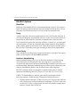
Programming Overview . . . . . . . . . . . . . . . . . . . . . . . . . . . . . . . . . . . . . . . . . . . . . . . . . . . . . . . . . . .
Scanning Sequence Examples . . . . . . . . . . . . . . . . . . . . . . . . . . . . . . . . . . . . . . . . . . . . . . . . . . . . . .
Errors While Scanning. . . . . . . . . . . . . . . . . . . . . . . . . . . . . . . . . . . . . . . . . . . . . . . . . . . . . . . . .
Parameter Descriptions . . . . . . . . . . . . . . . . . . . . . . . . . . . . . . . . . . . . . . . . . . . . . . . . . . . . . . . . . . . .
Set Parameter Defaults . . . . . . . . . . . . . . . . . . . . . . . . . . . . . . . . . . . . . . . . . . . . . . . . . . . . . . . .
Host Interface Code . . . . . . . . . . . . . . . . . . . . . . . . . . . . . . . . . . . . . . . . . . . . . . . . . . . . . . . . . . .
ii
6-1
6-2
6-2
6-3
6-3
6-3
Code Types . . . . . . . . . . . . . . . . . . . . . . . . . . . . . . . . . . . . . . . . . . . . . . . . . . . . . . . . . . . . . . . . . . 6-3
Code Lengths . . . . . . . . . . . . . . . . . . . . . . . . . . . . . . . . . . . . . . . . . . . . . . . . . . . . . . . . . . . . . . . . 6-3
Code 39 Full ASCII . . . . . . . . . . . . . . . . . . . . . . . . . . . . . . . . . . . . . . . . . . . . . . . . . . . . . . . . . . . 6-4
Decode Options . . . . . . . . . . . . . . . . . . . . . . . . . . . . . . . . . . . . . . . . . . . . . . . . . . . . . . . . . . . . . . 6-5
UPC-A and -E Preamble . . . . . . . . . . . . . . . . . . . . . . . . . . . . . . . . . . . . . . . . . . . . . . . . . . . . . . . 6-8
Pause Duration . . . . . . . . . . . . . . . . . . . . . . . . . . . . . . . . . . . . . . . . . . . . . . . . . . . . . . . . . . . . . . . 6-8
Prefix/Suffix Values . . . . . . . . . . . . . . . . . . . . . . . . . . . . . . . . . . . . . . . . . . . . . . . . . . . . . . . . . . 6-8
Data Transmission Formats . . . . . . . . . . . . . . . . . . . . . . . . . . . . . . . . . . . . . . . . . . . . . . . . . . . . 6-9
Laser Control . . . . . . . . . . . . . . . . . . . . . . . . . . . . . . . . . . . . . . . . . . . . . . . . . . . . . . . . . . . . . . . 6-10
RS-232C Options . . . . . . . . . . . . . . . . . . . . . . . . . . . . . . . . . . . . . . . . . . . . . . . . . . . . . . . . . . . . 6-11
Intercharacter Delay . . . . . . . . . . . . . . . . . . . . . . . . . . . . . . . . . . . . . . . . . . . . . . . . . . . . . . . . . 6-16
Transmit Code ID Character . . . . . . . . . . . . . . . . . . . . . . . . . . . . . . . . . . . . . . . . . . . . . . . . . . 6-16
Transmit AIM ID Character . . . . . . . . . . . . . . . . . . . . . . . . . . . . . . . . . . . . . . . . . . . . . . . . . . . 6-16
Ignore Unknown Characters . . . . . . . . . . . . . . . . . . . . . . . . . . . . . . . . . . . . . . . . . . . . . . . . . . 6-16
OCIA Clock Polarity . . . . . . . . . . . . . . . . . . . . . . . . . . . . . . . . . . . . . . . . . . . . . . . . . . . . . . . . . 6-16
OCIA Transmit Timeout . . . . . . . . . . . . . . . . . . . . . . . . . . . . . . . . . . . . . . . . . . . . . . . . . . . . . . 6-17
NCR 2152 Fast Transmit . . . . . . . . . . . . . . . . . . . . . . . . . . . . . . . . . . . . . . . . . . . . . . . . . . . . . . 6-17
IBM 4683/93 Magstripe Communications . . . . . . . . . . . . . . . . . . . . . . . . . . . . . . . . . . . . . . . 6-17
International Keypad Emulation . . . . . . . . . . . . . . . . . . . . . . . . . . . . . . . . . . . . . . . . . . . . . . . 6-17
International Keypad Emulation Fast Transmit . . . . . . . . . . . . . . . . . . . . . . . . . . . . . . . . . . 6-17
National Keyboard Types. . . . . . . . . . . . . . . . . . . . . . . . . . . . . . . . . . . . . . . . . . . . . . . . . . . . . 6-18
Set Transmission Frequency. . . . . . . . . . . . . . . . . . . . . . . . . . . . . . . . . . . . . . . . . . . . . . . . . . . 6-20
Wait for Host Interface Response Time . . . . . . . . . . . . . . . . . . . . . . . . . . . . . . . . . . . . . . . . . 6-20
Parameter Selections . . . . . . . . . . . . . . . . . . . . . . . . . . . . . . . . . . . . . . . . . . . . . . . . . . . . . . . . . . . . . 6-21
Beeper Definitions . . . . . . . . . . . . . . . . . . . . . . . . . . . . . . . . . . . . . . . . . . . . . . . . . . . . . . . . . . . . . . . 6-24
Standard Use. . . . . . . . . . . . . . . . . . . . . . . . . . . . . . . . . . . . . . . . . . . . . . . . . . . . . . . . . . . . . . . . 6-24
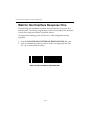
Parameter Menu Scanning . . . . . . . . . . . . . . . . . . . . . . . . . . . . . . . . . . . . . . . . . . . . . . . . . . . . 6-25
Code 39 Scan And Store . . . . . . . . . . . . . . . . . . . . . . . . . . . . . . . . . . . . . . . . . . . . . . . . . . . . . . 6-25
Code 39 Buffering . . . . . . . . . . . . . . . . . . . . . . . . . . . . . . . . . . . . . . . . . . . . . . . . . . . . . . . . . . . . . . . 6-26
Buffer Data . . . . . . . . . . . . . . . . . . . . . . . . . . . . . . . . . . . . . . . . . . . . . . . . . . . . . . . . . . . . . . . . . 6-26
Clear Transmission Buffer . . . . . . . . . . . . . . . . . . . . . . . . . . . . . . . . . . . . . . . . . . . . . . . . . . . . 6-26
Transmit Buffer . . . . . . . . . . . . . . . . . . . . . . . . . . . . . . . . . . . . . . . . . . . . . . . . . . . . . . . . . . . . . 6-27
Overfilling Transmission Buffer . . . . . . . . . . . . . . . . . . . . . . . . . . . . . . . . . . . . . . . . . . . . . . . 6-27
Attempt to Transmit an Empty Buffer . . . . . . . . . . . . . . . . . . . . . . . . . . . . . . . . . . . . . . . . . . 6-27
Default Table. . . . . . . . . . . . . . . . . . . . . . . . . . . . . . . . . . . . . . . . . . . . . . . . . . . . . . . . . . . . . . . . . . . . 6-28
Terminal Specific RS-232C Defaults . . . . . . . . . . . . . . . . . . . . . . . . . . . . . . . . . . . . . . . . . . . . . . . . 6-31
Chapter 7. Parameter Menus
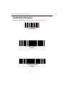
Set Default Parameter . . . . . . . . . . . . . . . . . . . . . . . . . . . . . . . . . . . . . . . . . . . . . . . . . . . . . . . . . . . . . 7-2
Host Interface . . . . . . . . . . . . . . . . . . . . . . . . . . . . . . . . . . . . . . . . . . . . . . . . . . . . . . . . . . . . . . . . . . . . 7-3
Code Type . . . . . . . . . . . . . . . . . . . . . . . . . . . . . . . . . . . . . . . . . . . . . . . . . . . . . . . . . . . . . . . . . . . . . . 7-17
Code Lengths . . . . . . . . . . . . . . . . . . . . . . . . . . . . . . . . . . . . . . . . . . . . . . . . . . . . . . . . . . . . . . . . . . . 7-22
Decode Options . . . . . . . . . . . . . . . . . . . . . . . . . . . . . . . . . . . . . . . . . . . . . . . . . . . . . . . . . . . . . . . . . 7-29
iii
UPC-A Preamble . . . . . . . . . . . . . . . . . . . . . . . . . . . . . . . . . . . . . . . . . . . . . . . . . . . . . . . . . . . . . . . .
UPC-E Preamble. . . . . . . . . . . . . . . . . . . . . . . . . . . . . . . . . . . . . . . . . . . . . . . . . . . . . . . . . . . . . . . . .
Pause Duration . . . . . . . . . . . . . . . . . . . . . . . . . . . . . . . . . . . . . . . . . . . . . . . . . . . . . . . . . . . . . . . . . .
Prefix/Suffix Values . . . . . . . . . . . . . . . . . . . . . . . . . . . . . . . . . . . . . . . . . . . . . . . . . . . . . . . . . . . . .
Data Transmission Formats . . . . . . . . . . . . . . . . . . . . . . . . . . . . . . . . . . . . . . . . . . . . . . . . . . . . . . .
Magstripe Options . . . . . . . . . . . . . . . . . . . . . . . . . . . . . . . . . . . . . . . . . . . . . . . . . . . . . . . . . . .
Laser Control . . . . . . . . . . . . . . . . . . . . . . . . . . . . . . . . . . . . . . . . . . . . . . . . . . . . . . . . . . . . . . . . . . .
Baud Rate . . . . . . . . . . . . . . . . . . . . . . . . . . . . . . . . . . . . . . . . . . . . . . . . . . . . . . . . . . . . . . . . . . . . . .
Parity . . . . . . . . . . . . . . . . . . . . . . . . . . . . . . . . . . . . . . . . . . . . . . . . . . . . . . . . . . . . . . . . . . . . . . . . . .
Check Parity . . . . . . . . . . . . . . . . . . . . . . . . . . . . . . . . . . . . . . . . . . . . . . . . . . . . . . . . . . . . . . . . . . . .
Hardware Handshaking . . . . . . . . . . . . . . . . . . . . . . . . . . . . . . . . . . . . . . . . . . . . . . . . . . . . . . . . . .
Software Handshaking . . . . . . . . . . . . . . . . . . . . . . . . . . . . . . . . . . . . . . . . . . . . . . . . . . . . . . . . . . .
Serial Response Timeout. . . . . . . . . . . . . . . . . . . . . . . . . . . . . . . . . . . . . . . . . . . . . . . . . . . . . . . . . .
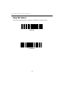
Stop Bit Select . . . . . . . . . . . . . . . . . . . . . . . . . . . . . . . . . . . . . . . . . . . . . . . . . . . . . . . . . . . . . . . . . . .
ASCII Data Format. . . . . . . . . . . . . . . . . . . . . . . . . . . . . . . . . . . . . . . . . . . . . . . . . . . . . . . . . . . . . . .
RTS Line State. . . . . . . . . . . . . . . . . . . . . . . . . . . . . . . . . . . . . . . . . . . . . . . . . . . . . . . . . . . . . . . . . . .
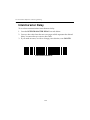
Intercharacter Delay . . . . . . . . . . . . . . . . . . . . . . . . . . . . . . . . . . . . . . . . . . . . . . . . . . . . . . . . . . . . .
Transmit Code ID Character . . . . . . . . . . . . . . . . . . . . . . . . . . . . . . . . . . . . . . . . . . . . . . . . . . . . . .
Transmit AIM Code ID . . . . . . . . . . . . . . . . . . . . . . . . . . . . . . . . . . . . . . . . . . . . . . . . . . . . . . . . . . .
Ignore Unknown Characters . . . . . . . . . . . . . . . . . . . . . . . . . . . . . . . . . . . . . . . . . . . . . . . . . . . . . .
OCIA Clock Polarity . . . . . . . . . . . . . . . . . . . . . . . . . . . . . . . . . . . . . . . . . . . . . . . . . . . . . . . . . . . . .
OCIA Transmit Timeout . . . . . . . . . . . . . . . . . . . . . . . . . . . . . . . . . . . . . . . . . . . . . . . . . . . . . . . . . .
NCR 2152 Fast Transmit . . . . . . . . . . . . . . . . . . . . . . . . . . . . . . . . . . . . . . . . . . . . . . . . . . . . . . . . . .
IBM 4683 Magstripe Communications . . . . . . . . . . . . . . . . . . . . . . . . . . . . . . . . . . . . . . . . . . . . . .
International Keypad Emulation . . . . . . . . . . . . . . . . . . . . . . . . . . . . . . . . . . . . . . . . . . . . . . . . . . .
International Keypad Emulation Fast Transmit . . . . . . . . . . . . . . . . . . . . . . . . . . . . . . . . . . . . . .
National Keyboard Types. . . . . . . . . . . . . . . . . . . . . . . . . . . . . . . . . . . . . . . . . . . . . . . . . . . . . . . . .
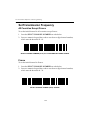
Set Transmission Frequency. . . . . . . . . . . . . . . . . . . . . . . . . . . . . . . . . . . . . . . . . . . . . . . . . . . . . . .
All Countries Except France . . . . . . . . . . . . . . . . . . . . . . . . . . . . . . . . . . . . . . . . . . . . . . . . . . .
France. . . . . . . . . . . . . . . . . . . . . . . . . . . . . . . . . . . . . . . . . . . . . . . . . . . . . . . . . . . . . . . . . . . . . .
Wait for Host Interface Response Time . . . . . . . . . . . . . . . . . . . . . . . . . . . . . . . . . . . . . . . . . . . . .
Reserved For Future Use. . . . . . . . . . . . . . . . . . . . . . . . . . . . . . . . . . . . . . . . . . . . . . . . . . . . . . . . . .
Pairing . . . . . . . . . . . . . . . . . . . . . . . . . . . . . . . . . . . . . . . . . . . . . . . . . . . . . . . . . . . . . . . . . . . . . . . . .
7-37
7-38
7-39
7-42
7-46
7-48
7-53
7-56
7-58
7-59
7-60
7-61
7-62
7-65
7-66
7-67
7-68
7-71
7-72
7-73
7-74
7-75
7-78
7-79
7-80
7-81
7-82
7-84
7-84
7-84
7-87
7-90
7-97
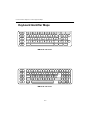
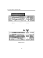
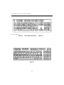
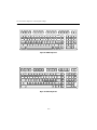
Chapter 8. Keyboard Maps
ASCII Table . . . . . . . . . . . . . . . . . . . . . . . . . . . . . . . . . . . . . . . . . . . . . . . . . . . . . . . . . . . . . . . . . . . . . . 8-1
Keyboard Identifier Maps. . . . . . . . . . . . . . . . . . . . . . . . . . . . . . . . . . . . . . . . . . . . . . . . . . . . . . . . . . 8-5
Index
iv
About This Manual
The LS 3070 Product Reference Guide provides general instructions for setup,
operation, troubleshooting, maintenance, and programming.
Notational Conventions
The following conventions are used in this document:
• Bullets (•) indicate:
- action items
- lists of alternatives
- lists of required steps that are not necessarily sequential
• Sequential lists (e.g., those that describe step-by-step procedures) appear
as numbered lists.
Related Publications
• LS 3070 Quick Reference Guide
70-19993-0X
Service Information
If you have a problem with your equipment, contact the Symbol Support
Center. Before calling, have the model number, serial number, and several of
your bar code symbols at hand.
Call the Support Center from a phone near the scanning equipment so that the
service person can try to talk you through your problem. If the equipment is
found to be working properly and the problem is symbol readability, the
Support Center will request samples of your bar codes for analysis at our plant.
If your problem cannot be solved over the phone, you may need to return your
equipment for servicing. If that is necessary, you will be given specific
directions.
About-i
LS 3070 Product Reference Guide: About This Manual
Note: Symbol Technologies is not responsible for any damages incurred during shipment if the approved shipping container is not used. Shipping the
units improperly can possibly void the warranty. If the original shipping container was not kept, contact Symbol to have another sent to you.
Symbol Support Center
In the U.S.A, for service information, warranty information or technical
assistance, call:
SYMBOL SUPPORT CENTER
1-800-653-5350
If you purchased your Symbol product from a Symbol Business Partner,
contact that Business Partner for service.
Canada
Mississauga, Ontario
Canadian Headquarters
(905) 629-7226
Europe
Wokingham, England
European Headquarters
0734-771-222 (Inside UK)
+441-734-771222 (Outside UK)
Asia
Singapore
Symbol Technologies Asia, Inc.
337-6588 (Inside Singapore)
+65-337-6588 (Outside Singapore)
About-ii
Chapter 1
The LS 3070 Cordless Scanner
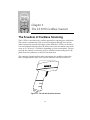
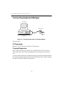
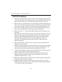
The Freedom of Cordless Scanning
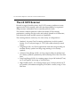
The LS 3070 is a revolutionary, cordless approach to capturing bar coded data.
The scanner communicates with your host computer through a low-power
radio transmission instead of through a cable. With the LS 3070, you are free to
scan and transmit without a physical cable to limit your movement, from as far
away as 30 - 50 feet (9 - 15 meters), depending on your environment. This lets
you take the scanner to where the work is, whether on the loading dock, the
plant floor, the warehouse, or the POS checkout area.
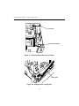
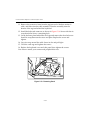
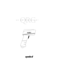
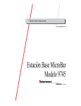
The scanning system has three main components: the cordless scanner, the
base/charger interface unit, and a cable to interface with the host device.
Figure 1-1. The LS 3070 Cordless Scanner
1-1
LS 3070 Product Reference Guide: The LS 3070 Cordless Scanner
The LS 3070 Scanner
Housed in rugged, durable plastic, the LS 3070 scanner combines accurate,
aggressive bar code scanning with solid state dependability. Its ergonomic
design ensures comfortable use for extended periods of time.
This scanner combines premium visible laser diode (VLD) scanning
performance, reading color bar codes and symbols printed on all substrates,
with advanced decode and RF transceiver capabilities.
The scanning element can be any of a wide variety of configurations:
• Standard - for most Class II scanning applications, in which symbol
density (5 to 55 mil) and range (0 - 35 in.) fall within relatively normal
ranges.
• Long Range (LR) - for Class II applications with short range reading on
medium density symbols and long range reading on low density
symbols.
• Advanced Long Range (ALR) - for long range reading on medium and
low-density symbols, optimized by the increased power of the Class IIIA
laser.
• Extra Long Range (XLR) - for scanning ranges of up to 180 inches (457 cm)
on 55 mil symbols, also using a Class IIIA laser.
• High Visibility (HV) - for scanning ranges up to 33 inches (86 cm) on 55
mil symbols, and ambient sunlight up to 10,000 ft. candles, using a Class
IIIA laser.
1-2
LS 3070 Product Reference Guide: The LS 3070 Cordless Scanner
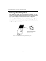
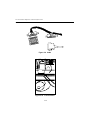
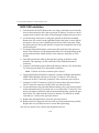
Rechargeable Battery Pack
In the handle of the scanner, there is a rechargeable NiCad battery pack. This
provides all power to the scanner during normal operation. It provides 360 mA
hours, which is sufficient for normal operation during an 8-hour shift.
When fully depleted, the battery module can be recharged to full charge within
two hours, with the LS 3070 inserted into the RL 470 base/charger unit.
Alternatively, the battery module can be recharged in the Universal Four-Slot
Charger/Recharger within 8 hours.
Ni-Cd
Nickel-cadmium rechargeable
battery. Must be recycled or
disposed of properly.
Figure 1-2. The LS 3070 Rechargeable Battery Pack
1-3
LS 3070 Product Reference Guide: The LS 3070 Cordless Scanner
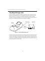
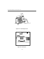
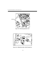
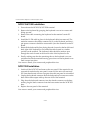
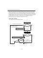
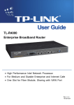
The Base/Charger Unit
The base/charger unit has two primary functions. First, it is the base station
interface that manages the flow of information from the scanner to the host
device. Second, it is a charging stand which charges the scanner’s battery
module (located in the handle) and also holds the scanner securely when it is
not in use. An LED indicates the status of battery charging.
Power Supply
Connection Port
Charge
Status LED
Host Cable
Connection
Magstripe
Reader
Connection
Port
Figure 1-3. RL 470 Base/Charger Unit
The base/charger unit communicates via radio transmission with the scanner
to receive bar code data from the scanner, confirm receipt of data back to the
scanner, and exchange configuration information. The base/charger unit also
formats the scanned bar code data as required and then transmits it to the host
system through the attached cable.
1-4
Chapter 2
Setup
Unpacking
Remove the LS 3070, the RL 470 base/charger unit, and the host interface cable
from its packing and inspect each for evidence of physical damage. If any
equipment was damaged in transit, call the Symbol Support Center at the
number in the front matter.
KEEP THE PACKING. It is the approved shipping container and should be
used if you ever need to return your equipment for servicing.
Connecting the Cable to the Base/Charger
Unit
The cable connects to the base/charger in the same way but to each host
terminal differently. For complete details per terminal type, refer to the RL 470
Base Station Interface Guide.
Installation Tip — Optimizing RF
Performance
The LS 3070 scanning system is equipped with a low power 2.4 Ghz radio.
Depending on environmental conditions, the LS 3070 can have an RF
transmission range of 30 - 50 feet (9 - 15 meters).
Where environmental objects affect RF range and performance, do the
following when you install the LS 3070 scanning system. This will help assure
peak performance.
2-1
LS 3070 Product Reference Guide: Setup
The RL 470 base station is a charger, host interface, and — significantly —
receiving station for RF transmission. Therefore, do not install the RL 470
inaccessibly under a table or buried in a desk drawer. At a minimum, mount
the RL 470 on a table or desk top. For optimum RF performance, especially in
difficult environments, mount the RL 470 on a wall as high as possible. But
keep in mind the limits of interface cable length and charging accessibility.
Proper base positioning gives you the best possible range and coverage
performance from the LS 3070 cordless scanning system.
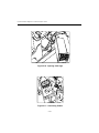
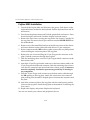
Inserting the Scanner Into and Removing
Scanner from Base/Charger
To insert the scanner into the base/charger:
1. First, place the nose to the scanner into the large rectangular receptacle of
the base/charger.
2. Then place the scanner handle into the opening of the smaller, latched
receptacle and press down firmly until the bottom of the handle seats
snugly into the receptacle and engages the latch.
Caution
Use of excessive force in placing the scanner into the base can
damage the charging contacts on the shoe of the scanner or in the
receptacle of the base. Such damage can interfere with or prevent
charging of the scanner’s batteries by the base.
3. To remove the scanner from the base/charger, grasp the handle of the
scanner and lift the bottom of the handle out of the latched receptacle,
thereby freeing the scanner from the base.
Caution
It is important to remove the scanner handle-first. Trying to remove the scanner nose-first can break latch in the base receptacle .
2-2
LS 3070 Product Reference Guide: Setup
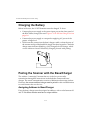
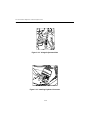
Charging the Battery
Before its first use, the LS 3070 batteries must be charged. To do so:
• Connect the power supply to the power input port on the front panel of
the RL 470 base/charger, shown in Figure 1-3: RL 470 Base/Charger Unit on
page 1-4.
• Connect the power supply to a receptacle supplying AC power of the
proper voltage level.
• Then insert the scanner into the base/charger cradle, so that the nose of
the scanner and tip of the handle fit snugly into the receptacles. Check the
charge status indicator (blinking = fully charged) for full charge, which
occurs within two hours. When fully charged, proceed with pairing.
Pairing the Scanner with the Base/Charger
The wireless “connection” between the two is the low power radio
transmission through RF transceivers in the both the scanner and base/
charger. The actual communication consists of bidirectional message packets.
However, the scanner and base/charger must be paired for this communication
to work between the two devices.
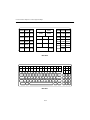
Assigning Address to Base/Charger
First, the base/charger must be assigned an address, with a value between 01
and 7E. Each base station must have a unique address.
2-3
LS 3070 Product Reference Guide: Setup
Note: When setting the address of the base, you
automatically set the initial frequency on which the
base and the scanner communicate. In order to
minimize possible interference between systems,
bases which are close to each other should be
assigned sequential addresses.
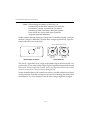
Set the address through setting two rotary dials, located by opening a panel on
the base/charger’s underside. Turn the base/charger upside down, open the
panel, and notice two rotary dials.
Insert Screwdriver in Slot
Switch
Panel
0
0
High Order
10 Position
Base/Charger Underside
Low Order
16 Position
Rotary Switches
The first is a 10-position (0 to 9, high order address digit) and the second a 16position (0 to F, low order address digit). Digits are printed sequentially around
each circle. Do not use positions 8 and 9. Setting the 10-position switch to 8 or 9 will
result in an error beep (5 long low tones) during pairing.
Set the desired address with a small screwdriver; possible addresses are listed
on the next page. Note that too large a screwdriver can damage the dials. When
the address is set, close the panel, turn the base/charger rightside up again.
2-4
LS 3070 Product Reference Guide: Setup
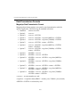
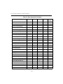
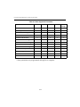
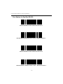
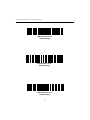
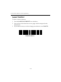
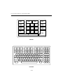
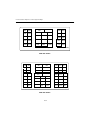
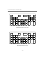
Possible Base/Charger Addresses
01
02 03
04
05
06
07
08
09
0A 0B 0C 0D 0E 0F
10
11
12 13
14
15
16
17
18
19
1A 1B 1C 1D 1E 1F
20
21
22 23
24
25
26
27
28
29
2A 2B 2C 2D 2E 2F
30
31
32 33
34
35
36
37
38
39
3A 3B 3C 3D 3E 3F
40
41
42 43
44
45
46
47
48
49
4A 4B 4C 4D 4E 4F
50
51
52 53
54
55
56
57
58
59
5A 5B 5C 5D 5E 5F
60
61
62 63
64
65
66
67
68
69
6A 6B 6C 6D 6E 6F
70
71
72 73
74
75
76
77
78
79
7A 7B 7C 7D 7E
Note: Each base station must have a unique address.
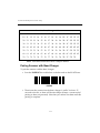
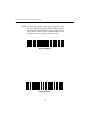
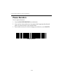
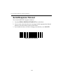
Pairing Scanner with Base/Charger
To pair the scanner with the base/charger:
• Scan the PAIRING bar code below or the bar code on the RL 470 base.
PAIRING
• Then insert the scanner into the base/charger’s cradle. You have 15
seconds to do this, or there will be error beeps (4 beeps = unsuccessful
pairing or base not powered). Note that you cannot scan data until this
pairing is complete.
2-5
LS 3070 Product Reference Guide: Setup
• At that time, through the scanner’s contact shoe, there is an exchange of
information (addressing, RF channels, etc.) between the scanner and the
base/charger’s cradle. This occurs in less than a second.
• After that exchange, the scanner and base/charger are paired. Successful
pairing is indicated by a warble beep; failure, or unsuccessful link, is
indicated by a Lo Lo Lo Lo beep.
Setting Transmission Frequency
Each scanner/base pair communicates on one of a number of channel
frequencies, which varies by country. In most countries, there are 80 available
channels (numbered 2 through 81); in France, there are only 9 channeles
(numbered 46 through 54).
The initial transmission frequency is determined by the base’s unique address,
so neighboring LS 3070 systems operate on different channels. This allows
them to transmit simultaneously without interfering with each other. Channel
separation is optimal between sequential base addresses, so base units closest
to each other should be assigned sequential base addresses if possible. (Note
that data is transmitted between a scanner and base so quickly that a number
of different LS 3070 systems can normally operate on the same channel without
noticeable interference.)
2-6
LS 3070 Product Reference Guide: Setup
Occasionally, there can be excessive interference on a channel from some other
source of radio transmissions. In this case, the default channel of a system can
be changed using the parameter codes for Set Transmission Frequency. If you
find a particular scanner/base pair has trouble communicating over a normal
operating distance, try setting different transmission frequencies to see if
performance improves. (The LS 3070 system changes channels automatically if
it encounters interference as much as 80% of the time over a continuous 5minute period.)
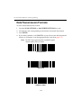
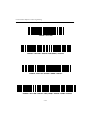
Note: To set trasmission frequency correctly, be sure to
use the correct Select Channel Number bar code for
your country, and to set a channel within the
allowable range.
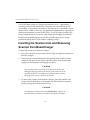
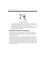
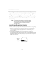
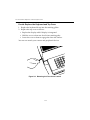
Installing a Magstripe Reader
If desired, install a magstripe reader. This may be done before or after pairing.
1. Remove the blank plug in the magstripe connection port on the base/
charger, and then plug the magstripe reader’s cable into this port, as
illustrated below.
2. The purpose of the blank plug is to protect the base/charger from
accidental damage that can be caused by static electrical discharge into the
magstripe connection port. Keep this plug in the port whenever the magstripe
reader is not connected.
Magstripe
Reader
Connection
Port
2-7
Chapter 3
Scanning with the LS 3070
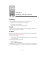
1. Ready
Before starting to scan bar codes for data collection, make sure:
• The base station is connected to the host device.
• The battery has been charged.
• The scanner is paired with the base/charger.
2. Test
Aim the scanner toward a bar code and press the trigger. When you press the
trigger, the scanning beam is energized.
3. Scan
Make sure the symbol you want to scan is within the proper scanning range.
(See Decode Zones beginning on page 3-6.)
Aim and press the trigger.
• The scan beam and red SCAN LED will light for about 3 seconds, or until
a successful decode.
The scanner has read the symbol when:
• You hear a beep.
• The green DECODE LED lights.
The LED stays green for up to one second if the trigger is down or disappears
if you release the trigger. The scanner powers down after a successful decode.
3-1
LS 3070 Product Reference Guide: Scanning with the LS 3070
If the scanning attempt ends in 4 error beeps, any of these may be true:
• Scanner is out of transmission range
• Scanner and base/charger are not paired
• Base/charger is not powered.
Hold at an Angle
Do not hold the scanner directly over the bar code. In this position, light can
bounce back into the scanner's exit window and prevent a successful decode.
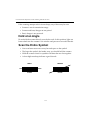
Scan the Entire Symbol
• Your scan beam must cross every bar and space on the symbol.
• The larger the symbol, the farther away you should hold the scanner.
• Hold the scanner closer for symbols with bars that are close together.
• A short high-tone beep indicates a good decode.
RIGHT
WRONG
012345
012345
3-2
LS 3070 Product Reference Guide: Scanning with the LS 3070
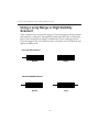
Using a Long Range or High Visibility
Scanner?
These scanners have two-position triggers. Press the trigger to the first detent
and center the “collapsed” aiming beam on the target bar code, as illustrated
below. The collapsed beam helps to establish the correct scanning position.
Press the trigger to the second detent, and a scan beam crosses all the bars and
spaces on the bar code.
FIRST TRIGGER POSITION
WRONG
RIGHT
SECOND TRIGGER POSITION
WRONG
RIGHT
3-3
LS 3070 Product Reference Guide: Scanning with the LS 3070
Scanning Transmission Range
RF Communication Errors
RF communication errors occur when the scanner is out of range from the base
during a scan data transmission attempt. An error is indicated by 6 beeps after
a bar code is scanned, although the bar code data appears on the host display.
This happens when the base receives the bar code data but the scanner did
NOT get the HIF response from the base, and therefore timed out.
The base reported an RF communication error because the NOMAD protocol
was not completed before timeout, however, transmitted the bar code data to
the host. Since the data has been sent, normal communications must be reestablished.
Restoring Normal RF Communications
Move the scanner closer to the base station so the transceivers can
communicate with each other better. Then re-scan the bar code. The scanner
sounds a good decode beep but the base does not display the bar code data,
because the data was already transmitted on the previous scan.
Resume normal scanning.
3-4
LS 3070 Product Reference Guide: Scanning with the LS 3070
What If ...
Nothing happens when you follow the operating
instructions?
You should
• Check that the power supply is attached to the base/charger.
• Check for loose cable connections at the base/charger and host device.
• Check the scanner’s battery pack.
• Make sure the device is programmed to read the type of bar code you
want to scan.
• Check the symbol to make sure it is not defaced.
• Try scanning similar symbols of the same code type.
• Check that the gas tank is not exhausted.*
• Make sure the scanner and base/charger have been successfully paired.
• Be sure you’re within the proper scanning and transmission range.
If you get frequent Transmit Errors (error beeps after decode):
• Check that you are within scanning transmit range. (See Scanning
Transmission Range on page 3-4.)
• Check that the scanner is successfully paired with the base/charger.
• Check that the base/charger is powered up and that its cable connections
are secure.
Note: If after performing these checks the symbol still
does not scan, contact your distributor or call the
Symbol Support Center. See Symbol Support Center
on page About-ii for the telephone number.
* The gas tank limits the amount of time the laser remains on within a given
period to conform to the requirements of specific laser output classifications.
3-5
LS 3070 Product Reference Guide: Scanning with the LS 3070
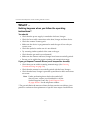
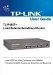
Decode Zones
LS 3070 Standard Range
10
25.4
5
12.7
0
0
5
12.7
10
25.4
Front of the
Scanner
.0055 In.
.0075 In.
.020 In. Minimum Element Width
.040 In. Minimum Element Width
.055 In. Minimum Element Width
In. Cm.
0
5
10
15
20
25
30
35
Inches
0
12.7
25.4
38.1
50.8
63.5
76.2
88.9
Cm.
Distance from Front of Scanner
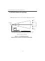
Figure 3-1. LS 3070 Decode Zone:
Depth of field as a function of minimum element width.
3-6
Width of Field
NOTE: Typical performance at 23o C (75o F) on high quality symbols.
LS 3070 Product Reference Guide: Scanning with the LS 3070
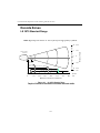
LS 3070LR Long Range
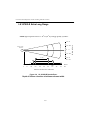
NOTE: Typical performance at 23o C (75o F) on high quality symbols.
30 76
10 25.4
Front of the
Scanner
0
7.5 Mil
0
10 25.4
10 Mil
20 51
15 Mil
30 76
20 Mil
40 Mil
0
0
20
10
25
51
30
76
In. Cm.
70 Mil Reflective
40
60
102 50
152
127
70
178
80
100
203 90
254 110 305 130 366
229
120
280
144
Inches
Cm
330
Distance from Front of Scanner
Figure 3-2. LS 3070LR Decode Zone:
Depth of field as a function of minimum element width.
3-7
Width of Field
20 51
LS 3070 Product Reference Guide: Scanning with the LS 3070
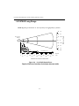
LS 3070ALR Advanced Long Range
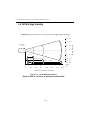
NOTE: Typical performance at 23o C (75o F) on high quality symbols.
10 25.4
Front of the
Scanner
0
0
10 25.4
15 Mil
20 51
In. Cm.
40 Mil
70 Mil Reflective
0
20
40
60
80
100 120
140
160 180
200 220 240
Inches
0
51
102
152
203
254
356
406
508
Cm
305
457
556
610
Distance from Front of Scanner
Figure 3-3. LS 3070ALR Decode Zone:
Depth of field as a function of minimum element width.
3-8
Width of Field
20 51
LS 3070 Product Reference Guide: Scanning with the LS 3070
LS 3070XLR Extra Long Range
NOTE: Typical performance at 23o C (75o F) on high quality symbols.
10 25.4
Front of the
Scanner
0
0
10 25.4
30 Mil
20 51
40 Mil
In. Cm.
55 Mil
0
20
40
60
80
100
120
0
51
102
152
203
254
305
140
160
180
Inches
356
406
457
Cm
Distance from Front of Scanner
Figure 3-4. LS 3070XLR Decode Zone:
Depth of field as a function of minimum element width.
3-9
Width of Field
20 51
LS 3070 Product Reference Guide: Scanning with the LS 3070
LS 3070HV High Visibility
Front of the
Scanner
.0075 In.
.020 In. Minimum Element Width
.040 In. Minimum Element Width
.055 In. Minimum Element Width
13
33
10
25.4
5
12.7
0
0
5
12.7
10
25.4
13 33
In. Cm.
0
5
10
15
20
25
30
34
Inches
0
12.7
25.4
38.1
50.8
63.5
76.2
86.4
Cm.
Distance from Front of Scanner
Figure 3-5. LS 3070HV Decode Zone:
Depth of field as a function of minimum element width.
3-10
Width of Field
NOTE: Typical performance at 23o C (75o F) on high quality symbols.
Chapter 4 Maintenance and
Specifications
Maintenance
Cleaning the exit window is the only maintenance required. A dirty window
may affect scanning accuracy.
• Do not allow any abrasive material to touch the window.
• Remove any dirt particles with a damp cloth.
• Wipe the window using a tissue moistened with ammonia/water.
• Do not spray water or other cleaning liquids directly into the window.
Recharging the Battery
As a charging stand, the base/charger recharges batteries in the scanner when
the scanner is in the cradle. The status of the scanner battery module
determines the charge rate. If the battery module is at full charge, the base/
charger supplies a trickle charge. If the battery module is at less than full
charge, there is a programmed charge. Note that the scanner can be removed
from the base/charger at any time.
When necessary, recharge the batteries. To do so:
• Connect the power supply to the power input port on the front panel of
the RL 470 base/charger, as illustrated below.
• Connect the power supply to a receptacle supplying AC power of the
proper voltage level.
• Then place the scanner into the base/charger cradle, so that the nose of
the scanner and tip of the handle fit snugly into the receptacles. Check the
charge status indicator (blinking = fully charged) for full charge, which
occurs within two hours. However, the scanner can be used on less than
full charge.
4-1
LS 3070 Product Reference Guide: Maintenance and Specifications
Power Supply
Connection Port
Figure 4-1. Recharging the LS 3070
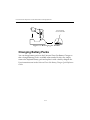
Changing Battery Packs
You can charge battery packs on the Universal Four Slot Battery Charger so
that a charged battery pack is available when needed. In this case, simply
remove the depleted battery pack and replace it with a freshly charged one.
User instructions are in the Universal Four-Slot Battery Charger Quick Reference
Guide.
4-2
LS 3070 Product Reference Guide: Maintenance and Specifications
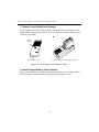
1. Remove Lower Handle from Scanner.
Using a probe, press in the release button on the handle, as indicated at the
right. With button pressed in below the outer housing, slide the battery pack
out from the handle.
Release
Button
Four Slot Charger with Charging Adapter
LS 3070 Battery Pack
Figure 4-2. Changing LS 3070 Battery Packs
2. Insert Charged Battery Pack in Handle.
With release button down, slide charged battery pack up into handle until it
locks into place and the release button pops up into place as well.
4-3
LS 3070 Product Reference Guide: Maintenance and Specifications
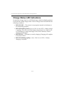
Charge Status LED Indications
On the base/charger, there is a red LED indicator which uses flashing patterns
to indicate the current charger status. The red Charge Status LED indicates the
following conditions:
• RED LED OFF — The scanner is not properly inserted or the battery is
not functioning properly.
• RED LED blinking slowly (1/8 sec. ON, 3/8 sec. OFF) — Battery charge
is pending. This can occur if the batttery temperature is too high or low
or if the battery is deeply discharged. After several minutes, normal
charging should begin.
• RED LED ON — The battery is actively charging. Charging will complete
in less than 2 hours.
• RED LED blinking rapidly (1/8 sec. ON, 1/8 sec. OFF) — Battery
charging is complete.
4-4
LS 3070 Product Reference Guide: Maintenance and Specifications
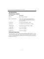
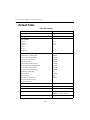
Accessories
Standard Accessories
Part Number
Description
RL 470
Base/interface charger
Base/Charger Cable:
Cables are available for most applications.
See the Electronic ProductOrdering Guide for
more information.
70-10294-01
LS 3070 Product Reference Guide
70-10538-01
LS 3070 Advanced Programmer’s Guide
70-10294-01Q
LS 3070 Series Quick Reference Guide
50-04000-041
117 V Power Supply
50-04000-040
220 V Power Supply
50-04000-037
100 V Power Supply
Optional Accessories
Optional accessories, listed in the Electronic Product Ordering Guide, include
various rechargers, magstripe readers, stands, and holders, which are supplied
at extra cost. Additional units of standard accessories listed above may also be
purchased at extra cost.
4-5
LS 3070 Product Reference Guide: Maintenance and Specifications
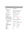
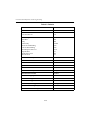
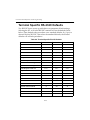
LS 3070 Standard Technical Specifications
ITEM
Power Requirements:
Scanner
Base/Charger
DESCRIPTION
4.75 to 14 VDC; 210 mA @ 5 VDC Typical.
5 VDC ± 10% @ 190 mA Typical.
12 VDC ± 10% @ 400 mA Typical.
Scan Repetition Rate
Approximately 36 (± 3) scans/sec
(bidirectional)
Start-up Time
<50 msec. from scan enable
Data Acquisition Time
<110 msec. from scan enable
Skew Tolerance
± 65° from normal
Pitch Angle
± 55° from normal
Decode Depth of Field
See LS 3070 Standard Range on page 3-6
Minimum Element Width
0.005 in.
.127 mm
Maximum Element Width
0.2 in.
5.08 mm
Print Contrast Minimum
20% absolute dark/light reflectance
differential, measured at 675 nm.
Ambient Light Immunity
Artificial Lighting
Sunlight
450 ft. candles
8000 ft. candles
Durability
6-ft. drop to concrete
Operating Temperature
0° to 40°C
32° to 104°F
Storage Temperature
-40° to 60°C
-40° to 140°F
Humidity
5% to 95% (non-condensing)
Height
6.3 in.
16 cm
Length
5 in.
12.7 cm
Width
2.8 in.
7.1 cm
CDRH Class
I, II
4-6
4844 lux
86112 lux (@8 in. on low
density bar codes)
LS 3070 Product Reference Guide: Maintenance and Specifications
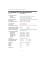
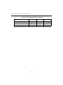
LS 3070LR Technical Specifications
ITEM
Power Requirements:
Scanner
Base/Charger
DESCRIPTION
Scan Repetition Rate
Start-up Time
Approximately 36 (± 3) scans/sec
(bidirectional)
<50 msec. from scan enable
Data Acquisition Time
<110 msec. from scan enable
Skew Tolerance
± 60° from normal
Pitch Angle
± 45° from normal
Decode Depth of Field
See LS 3070LR Long Range on page 3-7
Minimum Element Width
0.007 in.
.178 mm
Maximum Element Width
0.2 in.
5.08 mm
Print Contrast Minimum
50% absolute dark/light reflectance
differential, measured at 675 nm.
4.75 to 14 VDC; 210 mA @ 5 VDC Typical.
5 VDC ± 10% @ 190 mA Typical.
12 VDC ± 10% @ 400 mA Typical.
Ambient Light Immunity
Incandescent
Fluorescent
Sodium Vapor
Mercury Vapor
Sunlight
Durability
450 ft. candles
4844 lux
450 ft. candles
4844 lux
450 ft. candles
4844 lux
450 ft. candles
4844 lux
8000 ft. candles 86112 lux
6-ft. drop to concrete
Operating Temperature
0° to 40°C
32° to 104°F
Storage Temperature
-40° to 60°C
-40° to 140°F
Humidity
5% to 95% (non-condensing)
Height
6.3 in.
16 cm
Length
5 in.
12.7 cm
Width
2.8 in.
7.1 cm
CDRH Class
II
4-7
LS 3070 Product Reference Guide: Maintenance and Specifications
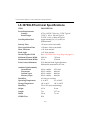
LS 3070ALR Technical Specifications
ITEM
Power Requirements:
Scanner
Base/Charger
DESCRIPTION
Scan Repetition Rate
Start-up Time
Approximately 36 (± 3) scans/sec (bidirectional)
<50 msec. from scan enable
Data Acquisition Time
<110 msec. from scan enable
Skew Tolerance
± 60° from normal
Pitch Angle
± 45° from normal
Decode Depth of Field
See LS 3070ALR Advanced Long Range on page 3-8
Minimum Element Width
0.015 in.
.380 mm
Maximum Element Width
0.1 in.
2.54 mm
Print Contrast Minimum
50% absolute dark/light reflectance differential,
measured at 675 nm.
4.75 to 14 VDC; 210 mA @ 5 VDC Typical.
5 VDC ± 10% @ 190 mA Typical.
12 VDC ± 10% @ 400 mA Typical.
Ambient Light Immunity
Incandescent
Fluorescent
Sodium Vapor
Mercury Vapor
Sunlight
450 ft. candles
450 ft. candles
450 ft. candles
450 ft. candles
8000 ft. candles
Durability
6-ft. drop to concrete
Operating Temperature
0° to 40°C
32° to 104°F
Storage Temperature
-40° to 60°C
-40° to 140°F
Humidity
5% to 95% (non-condensing)
Height
6.3 in.
16 cm
Length
5 in.
12.7 cm
Width
2.8 in.
7.1 cm
CDRH Class
IIIA
4-8
4844 lux
4844 lux
4844 lux
4844 lux
86112 lux
LS 3070 Product Reference Guide: Maintenance and Specifications
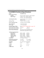
LS 3070XLR Technical Specifications
ITEM
Power Requirements:
Scanner
Base/Charger
DESCRIPTION
4.75 to 14 VDC; 210 mA @ 5 VDC Typical.
5 VDC ± 10% @ 190 mA Typical.
12 VDC ± 10% @ 400 mA Typical.
Scan Repetition Rate
Approximately 36 (± 3) scans/sec
(bidirectional)
Start-up Time
<50 msec. from scan enable
Data Acquisition Time
<110 msec. from scan enable
Skew Tolerance
± 60° from normal
Pitch Angle
± 45° from normal
Decode Depth of Field
See LS 3070XLR Extra Long Range on page 3-9
Minimum Element Width
0.030 in.
.762 mm
Maximum Element Width
0.1 in.
2.54 mm
Print Contrast Minimum
50% absolute dark/light reflectance
differential, measured at 675 nm.
Ambient Light Immunity
Incandescent
Fluorescent
Sodium Vapor
Mercury Vapor
100 ft. candles
450 ft. candles
450 ft. candles
450 ft. candles
Durability
6-ft. drop to concrete
Operating Temperature
0° to 40°C
32° to 104°F
Storage Temperature
-40° to 60°C
-40° to 140°F
Humidity
5% to 95% (non-condensing)
Height
6.3 in.
16 cm
Length
5 in.
12.7 cm
Width
2.8 in.
7.1 cm
CDRH Class
IIIA
4-9
1076.4 lux
4844 lux
4844 lux
4844 lux
LS 3070 Product Reference Guide: Maintenance and Specifications
LS 3070HV Technical Specifications
ITEM
Power Requirements:
Scanner
Base/Charger
DESCRIPTION
Scan Repetition Rate
Approximately 36 (± 3) scans/sec
(bidirectional)
Start-up Time
<50 msec. from scan enable
Data Acquisition Time
<110 msec. from scan enable
Skew Tolerance
± 60° from normal
Pitch Angle
± 45° from normal
Decode Depth of Field
See LS 3070HV High Visibility on page 3-10
Minimum Element Width
0.0075 in.
.190 mm
Maximum Element Width
0.1 in.
2.54 mm
Print Contrast Minimum
25% absolute dark/light reflectance
differential, measured at 675 nm.
4.75 to 14 VDC; 210 mA @ 5 VDC Typical.
5 VDC ± 10% @ 190 mA Typical.
12 VDC ± 10% @ 400 mA Typical.
Ambient Light Immunity
Incandescent
Fluorescent
Sodium Vapor
Mercury Vapor
Sunlight
400 ft. candles
450 ft. candles
450 ft. candles
450 ft. candles
10,000 ft. candles
Durability
6-ft. drop to concrete
Operating Temperature
0° to 40°C
32° to 104°F
Storage Temperature
-40° to 60°C
-40° to 140°F
Humidity
5% to 95% (non-condensing)
Height
6.3 in.
16 cm
Length
5 in.
12.7 cm
Width
2.8 in.
7.1 cm
CDRH Class
IIIA
4-10
4305 lux
4844 lux
4844 lux
4844 lux
107640 lux
Chapter 5
Interface Guide
Connecting to a Host Device
In most cases, connecting your LS 3070’s base station to your host terminal is a
very simple operation. You need only plug the cable into your host. Typical
configurations are shown on the following pages. Some POS keyboards require
more intricate installation instructions. Those begin on page 5-6.
We recommend that you disconnect the power supply from the base station
prior to connecting or disconnecting cables.
Refer to Interfaces beginning on page 5-23 for the proper interface cable
assembly.
After you've connected your base station to your host terminal, refer to Chapter
6: Programming for programming instructions.
5-1
LS 3070 Product Reference Guide: Interface Guide
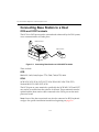
Connecting Base Station to a Host
OCIA and OCR Terminals
The OCIA or OCR port must be activated and referenced by the POS system,
or no communications will take place.
POS Terminal
Base Station
Figure 5-1. Connecting Base Station to OCIA/OCR Terminals
These include:
OCR
IBM 3653/3683/3684, Fujitsu 7770/7880/7990/8770/9000.
OCIA
NCR 2151/2152/2154/2155/2157/2126/2126-1120/2950/7050/7052,
Nixdorf 8812, ICL 9505/9507/9518.
The OCIA port on some terminals, specifically the NCR 2950, 2152 and 2257,
may not be accessible from the exterior of the unit. These terminals must be
opened and the base station cable connected to the OCIA port on the main
processor board.
Note: Some of the above terminals may also be connected as POS keyboard
wedges. See specific installation instructions beginning on page 5-6.
5-2
LS 3070 Product Reference Guide: Interface Guide
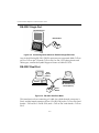
RS-232C Single Port
RS-232C Device
Base Station
Figure 5-2. Connecting Base Station to RS-232C Single-Port Host
Any of the following RS-232C (DB 25) connectors are supported: Male, TxD on
pin 2 or TxD on pin 3. Female, TxD on Pin 2 or Pin 3. For other pinouts and
cable types, contact the Symbol Support Center at 1-800-653-5350.
RS-232C Dual Port
Host
System
(Port 1)
RS-232C Auxiliary
Device (Port 2)
Base
Station
Figure 5-3. RS-232C Dual-Port Mode
This interface involves connecting a Y-cable, for which the male connector is
Port 1 and the female connector is Port 2. For IK-1500, male = TxD on Pin 2 and
female = TxD on Pin 3. For IK-1501, male = TxD on Pin 3 and female = TxD on
Pin 2
5-3
LS 3070 Product Reference Guide: Interface Guide
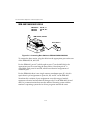
IBM 4683/4684/4693/4694
IBM 4683/4
IBM 4693
IBM 4694
5B, 9B, 17
5B, 9B, 9C«
9E
IBM 4683/84; 4693/94
Base Station
Figure 5-4. Connecting Base Station to IBM 4683/4684/4693/4694
To connect the base station, plug the cable into the appropriate port on the rear
of the IBM 4683/84, 4693/94.
For the IBM 4693, port 9C (which replaces port 17 on the 4683/84) is the
appropriate port for connecting the base station. Note that port 9C is
compatible with ports 9A and 9B, which have identical assignments of
connector pins.
For the IBM 4694, there is one single scanner attachment port, 9E, which is
equivalent in pin assignments to ports 9A, 9B, and 9C on the IBM 4693.
Note that this variation of port assignments over this range of models
represents electrical and mechanical changes only. For the IBM 4683/84 and
4693/94, communications between the attached scanning system and the
terminal’s operating system device driver programs remain the same.
5-4
LS 3070 Product Reference Guide: Interface Guide
Connecting Keyboard Wedges
Terminal
Base Station
Keyboard
Figure 5-5. Connecting Base Station to Keyboard Wedge
These include:
PC Keyboards
IBM PC/AT/XT, PS2-30/50/55SX/60/70 and clones.
Terminal Keyboards
DEC VT2XX/VT3XX/4XX; HP 700/92, 2392; IBM 3178/3278/3151/316X/
3179/3180/319X, 3278, 347X; Telex-Memorex 88, 122; Wyse 50/60/85/185/
150.
To connect the base station as a keyboard wedge, disconnect the keyboard from
the terminal, plug the keyboard connector into the base station cable, and plug
the other end of the cable into the terminal.
5-5
LS 3070 Product Reference Guide: Interface Guide
IBM 3683/3684 Installation
Caution
Install cables as described below. Failure to do so may result in hardware damage.
There are four basic steps to this installation:
1. Remove the IBM 3683/84 top cover.
2. Remove the keyboard.
3. Install the cable internally or externally.
4. Replace the keyboard and top cover.
First: Remove the IBM 3683/84 Top Cover
1. Set ON/OFF switch to OFF.
2. If display is integrated, disconnect the display cable).
3. Release the front cover latches. See Figure 5-6.
• Insert a spring hook through the gap between the top cover and base at
the side of the cash register near ON/OFF switch.
• Hook the spring latch and pull it outward to release.
• Lift the cover slightly at this corner and maintain it in lifted position to
prevent it from relatching.
• Repeat this procedure and release spring latch at opposite side of the
machine.
4. Holding the cover near the front on both sides, lift front, then push toward
rear of the machine to release it from the retaining tabs.
5. Disconnect cable from connector on the right side. See Figure 5-7.
6. Remove by lifting the entire cover straight up.
Second: Remove the Keyboard
Remove the keyboard by lifting it straight up through the retaining guides.
5-6
LS 3070 Product Reference Guide: Interface Guide
Third: Install the Cable Internally
The base station cable is installed internal to the IBM 3683/84 with the cable
exiting the rear of the terminal.
1. Remove the printer assembly as follows:
• Disconnect the printer ground strap (slide on connector) from the right
side of the printer, as shown in Figure 5-7).
• Slide the two printer locking tabs (black plastic) toward the front of the
register while pressing downward, as shown in Figure 5-8.
• Lift the printer up and out.
2. The cable to be installed is illustrated in Figure 5-9.
3. Mark an X on the side of J16 that faces the front of the terminal. Remove the
J16 connector from the keyboard connector bracket. Slide the J16 connector
under the printer mounting plate. See Figure 5-10.
4. Using a small screwdriver, remove the cable access door from the rear of
the register. Position the cable to connect J2 to J16 using the jumper PCB.
Make sure J2 and J16 are positioned so that the X and • align. (Some cables
are marked with TERM rather than •.) Use the tie wraps provided to secure
the connection. See Figure 5-11.
5. Slide J1 under the printer mounting plate to the keyboard access opening.
Pull it through the opening and secure it with the retaining clips (where J16
originally was). See Figure 5-12. (Some cables are marked with KBD or
Keyboard rather than •.)
6. Push the J2/J16 connection under the printer mounting plate. Replace the
cable access door at the rear of the register.
7. Replace the printer assembly as follows:
• Attach the ground strap to the right side of the assembly.
• Fasten the locking tabs by sliding them toward the rear of the register.
5-7
LS 3070 Product Reference Guide: Interface Guide
Fourth: Replace the Keyboard and Top Cover
1. Replace the keyboard down into the retaining glides.
2. Replace the top cover as follows:
• Replace the display cable if display is integrated.
• Hold the cover so that rear slots fit into retaining tabs.
• Lower the cover at front to engage the front side latches.
You can now attach your scanner and peripheral devices.
Figure 5-6. Releasing the Front Cover Latches
5-8
LS 3070 Product Reference Guide: Interface Guide
Connector
Printer Ground Strap
Figure 5-7. Disconnecting Cable from Connector
Locking Tab
Figure 5-8. Sliding Printer Locking Tabs
5-9
LS 3070 Product Reference Guide: Interface Guide
Figure 5-9. Cable
Figure 5-10. J16 Connector
5-10
LS 3070 Product Reference Guide: Interface Guide
Figure 5-11. Connecting J2 to J16
Figure 5-12. Securing J1
5-11
LS 3070 Product Reference Guide: Interface Guide
IBM 3653 Installation
1. Be sure the IBM 3653 terminal is powered-down. Open the door over the
ribbon cartridge as shown in Figure 5-13.
2. Loosen the right side panel screw (see Figure 5-13). Grasp the right panel
at top of the rear corner; pull out to the side and push back to remove the
panel.
3. Loosen the two screws behind the top of the keyboard cover. Lift and
remove the keyboard cover. See Figure 5-14.
4. From the bottom of the register, slide the cable retaining clips until the
cables are free. From inside the register, pass the base station cable (single
end) through the power cable hole. See Figure 5-15.
Caution
Use extreme care to avoid damaging the connector pins.
5. Loosen the screw on the base of the cash register near the bottom left side
of the card cage. Swing the card cage open by pulling on the left side. See
Figure 5-16.
6. Locate the keyboard connector to check for 5 volts DC. Using a DVM,
connect the GND (-) probe to the screw that holds the keyboard to the
chassis, and connect the POS (+) probe to the 5-volt lead on the TOP ROW
of the keyboard connector, second from right (see Figure 5-17). Turn on the
cash register. If the voltage is less than 5 volts, locate the voltage adjustment
hole on the power supply case behind the card cage (see Figure 5-18). Using
a flexible screw driver, adjust the potentiometer until the voltage is 5.0 to
5.1 volts. Turn off the register and remove the DVM.
7. Route cable under card cage to the front of the register.
8. Locate the keyboard connector on the keyboard and observe its orientation
while removing the connector.
9. Place shrink sleeve over the cable assembly (heat with blow dryer or heat
gun to shrink the sleeving if possible).
10. Insert the polarizing key into the top right corner socket. The polarizing
key is found in the bag containing the tie wrap.
5-12
LS 3070 Product Reference Guide: Interface Guide
11. Remove the protective foam from the register end of the base station Ycable, and insert into the cable assembly. Place the assembly near the
bottom of the register behind the keyboard.
12. Install the keyboard connector, as shown in Figure 5-19. Secure with the tie
wrap that doesn't have a mounting hole.
13. Locate the brass plate behind the card cage and remove the front left screw.
Install tie wrap between the screw and plate. Replace the screw and
tighten.
14. Loop tie wrap around the cable. Insert in slot and pull tight.
15. Close the card cage and tighten the screws.
16. Replace the keyboard cover and side panel, then tighten the screws.
You can now attach your scanner and peripheral devices.
Figure 5-13. Removing Panel
5-13
LS 3070 Product Reference Guide: Interface Guide
Screws
Figure 5-14. Removing Keyboard Cover
Figure 5-15. Sliding Base Station Cable Through Hole
5-14
LS 3070 Product Reference Guide: Interface Guide
Figure 5-16. Opening Card Cage
Figure 5-17. Connecting Probes
5-15
LS 3070 Product Reference Guide: Interface Guide
Figure 5-18. Voltage Adjustment Hole
Figure 5-19. Installing Keyboard Connector
5-16
LS 3070 Product Reference Guide: Interface Guide
NCR 280 Installation
1. Ensure that the NCR 280 is powered down and unplugged. Open the door
on the top, left-hand side and remove the two screws which fasten the steel
plate to the terminal cover. Slide the steel plate to the left to remove.
2. Remove the two round head screws from the back of the terminal. Be sure
the doors on the left and right side of the terminal are open and that there
are no keys inserted in the locks on the front. Lift off the terminal cover.
3. Locate the card edge connector to the left of the keyboard. Mark the top
side of the connector before removing it from the keyboard.
4. Remove the four “C” clips that hold the keyboard in place. Remove the
keyboard.
5. Feed the end of the RL 470 base station cable with the 2x8 header connector
under the large capacitor mounted horizontally in the terminal power
supply. Next feed the cable between the two large vertically-mounted
capacitors then through the hole in the plate adjacent to these two
capacitors. Feed through enough cable so that the cable reaches the
terminal keyboard.
6. Mate the 2x8 header connector to the connector on the interface board.
Note that pin 10 is keyed.
7. With the component side up on the interface board, connect the card edge
connector on the interface board to the card edge on the keyboard. The
interface board will be mounted under the keyboard PC board.
8. Connect the card edge connector, removed earlier from the keyboard, to the
interface board, with the marked side facing down.
9. Replace the keyboard with the interface board attached. Be sure the
interface board is installed so that it doesn't interfere with any cable
assemblies. Replace the “C” clips.
10. Remove any slack in the RL 470 base station cable by gently pulling it back
through the terminal power supply.
11. Using the cable tie provided, secure the base station cable to the cable
bundle near the capacitor, which is mounted horizontally approximately 6
1/2 in. from the rear of the terminal.
5-17
LS 3070 Product Reference Guide: Interface Guide
12. Cut a 1-in. diameter semicircle at the bottom left of the terminal cover,
approximately 6 1/2 in. from the back of the unit, so that when the cover is
replaced, this opening fits over the cable. Be sure to file down all sharp
edges.
13. Replace the terminal cover making sure that cable fits into the opening;
secure the two screws at the back of the terminal. Replace the steel plate to
the terminal cover and secure.
You can now attach your scanner and peripheral devices.
NCR 2151 Installation
1. Be sure the NCR 2151 terminal is powered-down. Remove the terminal's
front grille by loosening the two (2) screws (turn clockwise) that fasten the
grille down to the front of the terminal. Fully extend the card slide
assembly. Disengage the catches holding the board assemblies in place.
Then gently pull out the processor board (top board) until the connectors
at the rear of the board become visible. To prevent the board from falling
through the card slide assembly, it may be necessary to support the board
assembly during this phase.
2. Locate the integrated circuit designated U109 on the processor board. Note
U109's orientation by locating its pin 1; this is crucial for the replacement
that follows.
Note: U109 is socketed. Using a small screwdriver,
remove U109 from its mating socket. Replace the
part with the Terminal Retrofit Circuit provided
with the installation kit. Be sure that the
replacement part is oriented in the same direction
as the part it replaces.
3. On the far left side of the processor board, carefully remove the connector
marked I/O P7 from its mate (J7). Take the K8 T-board connector (p/n 2102977-01) from the shipping container, and connect J1 to J7 on the processor
board. This connection mates in one direction only. As the connectors are
not keyed, be sure the connecting pair is properly aligned.
4. Locate the J3 connector on the rear right side of the processor board. If a
cable mates to J3, remove it and note its orientation, as it must be returned
to the same position later.
5-18
LS 3070 Product Reference Guide: Interface Guide
5. Locate the end of the RL 470 base station cable that branches into a “Y”.
Slide that end under the board assembly inside the register. Leave enough
slack to make the connection required in the next few steps.
6. Mate the RL 470 base station cable “Y” branch ending in a 2 x13 female boxtype connector to P1 on the K8 T-board. Connector P1 is the middle
connector on the T-Board.
Note: Connector position 1 of the mating pair is keyed.
7. Locate connector P2 on the K8 T-board; it is the top connector on the board.
Mate P2 with the ribbon connector marked I/O P7. Be sure the ribbon
connector label I/O P7 faces up. Also be sure the left and right edges of the
two connectors line up. This check is very important, as the connectors are
not keyed.
8. Mate the RL 470 base station cable “Y” branch ending in a 2X6 female boxtype connector to P1 on the T-board (p/n 21-03428-01). Connector P1 is the
middle connector on the T-board.
Note: The connector position 1 of the mating pair is
keyed.
9. If J3 on the processor board had a cable mating to it, that cable must now
mate with connector P2 on the T-board (p/n 21-03428-01).
Note: The cable must have the same orientation it had
when removed from J3 on the processor board. If
no cable was mating with J3, then P2 on the
T-board (p/n 21-03428-01) is left unconnected.
10. Carefully slide the board assembly to its original position in the card slide.
Then return the card slide to its retracted position. Check that all cables
mating to the board assemblies are still firmly seated in position.
11. Locate the supplied cable fastener hardware. Using the hardware, secure
the RL 470 base station cable to one of the cable fastening posts located at
the bottom front edge of the terminal housing. Replace the grille removed
at the beginning of this procedure. The RL 470 base station cable should be
positioned so that it fits through a slot located at the bottom of the grille.
You can now attach your scanner and peripheral devices.
5-19
LS 3070 Product Reference Guide: Interface Guide
NCR 2152 Installation
1. Switch off the NCR 2152. Remove the two large, pan head screws from the
front of the terminal to allow the top section to open up. Use the two hood
support rods located to the sides of the housing to support the top section.
2. Locate the large steel plate covering the printed circuit board assembly.
Remove the two screws on the right-hand side of the plate. Loosen, but do
not remove, the two screws holding down the left side of the plate. Slide
the plate to the left, lift up and remove to expose the component side of the
processor board.
3. Locate the Keyboard Interface connector at the back left of the processor
board. This connector will be designated either J12 or J8, depending on the
processor board used. Mark the top of the connector with tape or a felt
marker.
4. Feed the base station cable up through the opening at the back of the
terminal. The opening is on the same side as the Keyboard Interface
connector.
5. Connect J1 of the base station cable to the mating connector, P1, on the cable
T-Connector provided (P1 is the middle connector).
Note: Position 16 for the connector pair is keyed.
6. Unplug the Keyboard Interface connector. Connect the Keyboard Interface
ribbon cable (marked side up) to P2 of the T-Connector. P2 is the top
connector on the T-Connector; position 2 of the connector pair is keyed.
7. Connect J1 of the T-Connector to J12/J8 on the terminal processor board.
The T-Connector can mate with J12/J8 in one direction only.
8. Locate and remove the pan head cable mounting screw on a flat steel panel
in the terminal housing. It is about 4 in. to one side of the T-Connector. Use
the tie provided to secure the cable to the terminal housing; replace the pan
head screw. The cable must be secured so that the T-Connector is seated
vertically (i.e., at 90°) to the processor board.
9. Replace the metal plate that covers the processor board.
10. Remove the hood supports and lower the top of the terminal into position.
Replace the two pan head screws to secure the top housing.
You can now attach your scanner and peripheral devices.
5-20
LS 3070 Product Reference Guide: Interface Guide
NCR 2154/2155 Installation
1. Power-down the NCR 2154/2155 POS terminal.
2. Remove the keyboard by grasping the keyboard cover at its corners and
lifting upward.
3. Remove the cable connecting the keyboard to the terminal’s main PC
board.
4. Install the LL 500 cable in place of the keyboard cable just removed. The
modular connector should be connected to J1 on the keyboard, and the 6pin square connector should be connected to J4 on the terminal’s main PC
board.
5. Reinstall the keyboard by first placing the tabs, located on the back left and
back right of the keyboard cover, behind the tabs located in a similar
position on the terminal. The keyboard cable should be made to pass
through the notch located at the rear left side of the keyboard cover.
6. Finally, making sure that the remaining tabs on the keyboard cover are
positioned inside the terminal housing, press down on the keyboard cover
until it snaps into place.
You can now attach your scanner and peripheral devices.
NCR 7052 Installation
1. Switch-off the NCR 7052 and remove the rear panel. If the terminal is not
powered-down before the rear panel is removed, the unit will turn itself
off. Note that the unit will turn on again when the rear panel is re-installed.
2. Unplug the keyboard connector. Run the keyboard-style connectors on the
base station data output cable up the rear well of the terminal.
3. Plug the male keyboard connector into the female connector on the base
station; plug the male connector from the base station into the NCR 7052
base.
4. Replace the rear panel of the terminal.
You can now attach your scanner and peripheral devices.
5-21
LS 3070 Product Reference Guide: Interface Guide
Fujitsu 9000 Installation
1. Switch-off the Fujitsu 9000, and disconnect the power. Push down on the
keyboard release latch below the keyboard. Pull the keyboard forward, lift
and remove
2. Press down the printer release tab. Push the printer back and remove. Press
down the display release tab. Push the display back and remove.
3. Remove the four screws securing the top plate to the chassis. Carefully lift
the top plate. Disconnect the 60-pin connector marked KB-PR-DISP from
the motherboard.
4. Remove one of the metal filler brackets at the left-rear corner of the chassis,
and insert the base station cable ends with the two 15-pin connectors.
5. By the connector marked KB on the top plate, remove the two phillips head
screws holding the connector plate to the top plate.
6. Remove the two screws holding the 15-pin D-type male connector to the
plate. Push the connector through the top plate.
7. Slide the insulating sleeve over the 15-pin D-type female connector on the
base station cable.
8. Attach the 15-pin D-type female connector on the base station cable to the
15-pin D-type male keyboard connector. Push the insulating sleeve down
over the two connectors and secure both sides with tie wraps. Connectors
must be completely insulated to prevent any possibility of shorting to
any component.
9. Push the 15-pin D-type male connector on the base station cable through
the KB opening on the top plate. Attach this connector to the connector
plate, making sure the small U-shaped spacer is between the connector and
the plate.
10. Attach the connector plate to the top plate with the small spacing washer
closest to the top plate. Attach the top plate to the terminal, re-inserting the
four screws.
11. Replace the display and printer. Replace the keyboard
You can now attach your scanner and peripheral devices.
5-22
LS 3070 Product Reference Guide: Interface Guide
Interfaces
Select the appropriate interface cable assembly for your host system.
Host
Type
Interface P/N
DEC VT 2XX/3XX/4XX
Fujitsu 7770, 7880, 7990, 8770
Fujitsu 9000
Fujitsu 9000
Wedge
OCR
OCR
Wedge
IK-1400
IK-0901
IK-0900
IK-0403
HP 700/XX, 239X
Wedge
IK-1301
RS-232C
TxD on Pin 2, Male
TxD on Pin 3, Male
TxD on Pin 2, Female
TxD on Pin 3, Female
Dual, TxD on Pin 2, Male
Dual, TxD on Pin 3, Male
RS-232C
RS-232C
RS-232C
RS-232C
RS-232C
RS-232C
IK-0801
IK-0802
IK-0803
IK-0800
IK-1500
IK-1501
IBM 3151
IBM 3161/319X
IBM 3178
IBM 3179, 3180
IBM 3278
IBM 347X
IBM AT/XT*
IBM PS/2* Model 30,50,55SX,60,70,80
IBM 3653
IBM 3653, 3683/3684
IBM 3683, 3684
IBM 4683/4684
IBM 4683/4684
IBM 4683/4684
Wedge
Wedge
Wedge
Wedge
Wedge
Wedge
Wedge
Wedge
Wedge
OCR
Wedge
Port 5B
Port 9B
Port 17
IK-0409
IK-0406
IK-1200
IK-0405
IK-1201
IK-0409
IK-0400
IK-0401
IK-0300
IK-0902
IK-0200
IK-0100
IK-1100
IK-0101
ICL 9505, 9507, 9518
ICL 9520
OCIA
OCIA
IK-1005
IK-1006
*And clones
5-23
LS 3070 Product Reference Guide: Interface Guide
Host
Type
NCR 280
NCR 2126-1120
NCR 2151
NCR 2152
NCR 2152/2257/2950
NCR 2154/2155/2157/7050
NCR 7052
NCR 7052
Wedge
OCIA
Wedge
Wedge
OCIA
OCIA
OCIA
Wedge
IK-0700
IK-1004
IK-0600
IK-0500
IK-1001
IK-1002
IK-1000
IK-0402
Nixdorf 8812
OCIA
IK-1003
Telex Memorex 88, 122
Wedge
IK-0400
Wyse 60, 85, 150, 150+, 185
Wedge
IK-1300
5-24
Interface P/N
Chapter 6
Programming
Programming Overview
Before programming, follow the instructions in the Chapter 2: Setup and Chapter
5: Interface Guide.
Programming occurs through use of bar code menus. Not all parameters,
however, apply to your specific host. For example, if you have an OCIA
terminal, RS-232C parameters such as baud rate and parity will not apply.
Simply ignore those parameters not designed for your application. If you're not
sure which parameters apply, refer to the Parameter Selections on page 6-21 for
your specific terminal type.
The first section of this chapter, Parameter Descriptions beginning on page 6-3,
defines parameters and the bar codes necessary to set those parameters.
To customize data for your specific needs, see the Advanced Programmer’s Guide.
Consult the Parameter Descriptions beginning on page 6-3 for explanations of
parameter types; Parameter Selections beginning on page 6-21 shows the
available parameters for various terminal types.
If the default values suit your requirements, all you need to do is scan the SET
DEFAULT bar code. Parameters other than default values can be set by
scanning sequences of bar codes. Chapter 7: Parameter Menus contain all the bar
codes necessary to program the scanner for each parameter selection.
6-1
LS 3070 Product Reference Guide: Programming
Scanning Sequence Examples
In most cases you need only scan one bar code to set a specific parameter. For
example, if you want to set the baud rate to 9600, simply scan the 9600 bar code
listed under Baud Rate. The base station will issue a warble tone, signifying a
successful parameter entry.
If you want to add or change prefixes and suffixes or customize the data
transmission format, you will have to scan several bar codes. This procedure is
described in Parameter Descriptions beginning on page 6-3.
Errors While Scanning
Don't worry if you make an error during a scanning sequence. Merely reenter
the correct parameter.
6-2
LS 3070 Product Reference Guide: Programming
Parameter Descriptions
Set Parameter Defaults
Scanning the SET DEFAULT bar code returns all parameters to the values
listed in the Default Table beginning on page 6-28.
Host Interface Code
Each Interface Cable Assembly defaults to a given host. These assemblies, their
corresponding defaults, and additional bar codes begin in Chapter 7: Parameter
Menus. In some cases, two bar codes may correspond to one interface type; this happens
when different software revisions exist for the same host type. If there are two bar codes
for your host type, try the first bar code; if that does not work, then try the second one.
Code Types
The bar code menu selections enable the scanner to decode any or all of the
following symbologies.
• UPC Versions A and E (EAN 8 and 13)
• Codabar
• Code 39
• Code 39 Full ASCII
• Discrete 2 of 5
• Interleaved 2 of 5
• Code 128
• MSI Plessey
• EAN 128
The scanner will autodiscriminate between all of the above symbologies,
except for Code 39 and Code 39 Full ASCII.
Code Lengths
Code lengths for certain code type (i.e., Code 39, Codabar, etc.) may be set for
any length, one or two discrete lengths, or lengths within a specific range. The
length of a code refers to the number of characters (i.e., human readable
characters) the code contains.
Length Within Range - This option allows you to decode a code type within a
specified range. For example to decode Code 39 characters containing between
4 and 12 characters, first scan Code 39 Length Within Range. Then scan 0, 4, 1
and 2 (single digit numbers must always be preceded by a leading zero).
6-3
LS 3070 Product Reference Guide: Programming
One Discrete Length - This option will allow you to decode only those codes
containing a selected length. For example, if you select D 2 of 5 One Discrete
Length, then scan 1, 4, the only D 2 of 5 codes decoded will be those containing
14 characters
Two Discrete Lengths - This option will allow you to decode only those codes
containing two selected lengths. For example, if you select D 2 of 5 Two
Discrete Lengths, then scan 0, 2, 1, 4, the only D 2 of 5 codes decoded will be
those containing 2 or 14 characters.
Any Length - Scanning this option allows you to decode the selected code type
containing any number of characters. For example, if you scan Codabar Any
Length, you will be able to decode a Codabar symbol containing any number
of characters.
Code 39 Full ASCII
The ASCII character set assigns a code for letters, punctuation marks,
numerals, and most control keystrokes on the keyboard.
The first 32 codes are non-printable and are assigned to keyboard control
characters such as BACKSPACE and RETURN. The other 96 are called
printable codes because all but SPACE and DELETE produce visible
characters.
Code 39 Full ASCII interprets the bar code control character ($ + % /)
preceding a Code 39 symbol and assigns an ASCII character value. For
example, when Code 39 Full ASCII is enabled and a +B is scanned, it will be
interpreted as b, %J as ?, and $H emulates the keystroke BACKSPACE.
Scanning ABC$M will output the keystroke equivalent of ABC ENTER.
The LS 3070 will not autodiscriminate between Code 39 and Code 39 Full
ASCII.
6-4
LS 3070 Product Reference Guide: Programming
Decode Options
Transmit UPC-E/UPC-A Check Digit
Select if decoded UPC symbols are transmitted with or without a check digit.
Convert UPC-E To UPC-A
Use this parameter to convert UPC-E (zero suppressed) decoded data to UPCA format before transmission. After conversion, data will follow UPC format
and be affected by UPC-A programming selections (e.g., Preamble, Check
Digit).
Ean Zero Extend
This parameter adds five leading zeros to decoded EAN-8 symbols to make
them compatible in format to EAN-13 symbols.
Xmit “No Decode” Message
This feature gives you the option to transmit “NR” when a symbol does not
decode. Prefixes and suffixes enabled will be appended around this message.
Decode UPC/EAN Supplemental
Select whether UPC/EAN is decoded with or without supplemental
characters. Supplementals are additionally appended characters (2 or 5)
according to specific code format conventions (e.g., UPC A+2, UPC E+2, EAN
8+2).
If UPC/EAN with supplemental characters is selected, UPC/EAN symbols
without supplemental characters won't be decoded. If UPC/EAN without
supplemental characters is selected and the scanner is presented with a UPC/
EAN plus supplemental symbol, the UPC/EAN will be decoded and the
supplemental characters ignored.
If autodiscrimination is chosen, the LS 3070 will, after additional processing to
ensure a good decode, transmit either. (NOTE: To minimize the risk of invalid
data transmission, it is recommended that you select whether to read or
ignore supplemental characters.)
6-5
LS 3070 Product Reference Guide: Programming
Code 39 Check Digit
When enabled, this parameter checks the integrity of a Code 39 symbol to
ensure it complies with a modulo 43 check digit algorithm.
ITF-14/EAN-13 Conversion
If your terminal supports EAN-13, this feature converts a 14 character I 2 of 5
code into EAN-13, and transmits to the host as EAN-13. In order to accomplish
this, the I 2 of 5 code must be enabled, one length (either LENGTH 1 or
LENGTH 2) must be set to 14, the code must have a leading zero and a valid
EAN-13 check digit.
Bi-Directional Redundancy for Codabar
This parameter applies only to Codabar symbols. When enabled, the bar code
must be decoded in both directions to be considered good.
MSI Plessey Check Digit
One or two digits at the end of the bar code that check the integrity of the data.
At least one check digit (default) is always required. Check digits are not
transmitted with the data.
Code 39 Buffering (Scan & Store)
When you select the scan and store option, all Code 39 symbols having a
leading space as a first character are temporarily buffered in the unit to be
transmitted later. The leading space is not buffered.
Decode of a valid Code 39 symbol with no leading space causes transmission
in sequence of all buffered data in a first-in first-out format, plus transmission
of the “triggering” symbol. See Code 39 Buffering beginning on page 6-26 for
further details.
When the scan and transmit option is selected, decoded Code 39 symbols
without leading spaces are transmitted without being stored in the buffer.
Scan and Store affects Code 39 decodes only. If you select scan and store, it is
recommended that you configure the scanner to decode Code 39 symbology
only.
6-6
LS 3070 Product Reference Guide: Programming
Beeper Volume
Select degree of volume — high or low.
Beep After Good Decode
Determine if the unit beeper will sound during normal scanning. Usually it is
desirable to operate the unit with the beeper enabled. In all cases, the beeper
operates during parameter menu scanning and indicates error conditions. See
Beeper Definitions beginning on page 6-24.
UPC/EAN Security Level
The LS 3070 offers four levels of decode security for UPC/EAN bar codes.
Increasing levels of security are provided for decreasing levels of bar code
quality. There is an inverse relationship between security and scanner
aggressiveness, so be sure to choose only that level of security necessary for
any given application.
• Security Level 0 - This is the default setting which allows the scanner to
operate in its most aggressive state, while providing sufficient security in
decoding “in spec” UPC/EAN bar codes.
• Security Level 1 - As bar code quality levels diminish, certain characters
become prone to mis-decodes before others (i.e., 1, 2, 7, 8). If you are
experiencing mis-decodes of poorly printed bar codes, and the misdecodes are limited to these characters, select this security level.
• Security Level 2 - If you are experiencing mis-decodes of poorly printed
bar codes, and the mis-decodes are not limited to characters 1, 2, 7 and 8,
select this security level.
• Security Level 3 - If you have tried Security Level 2, and are still
experiencing mis-decodes, select this security level. Be advised, selecting
this option is an extreme measure against mis-decoding severely out of
spec bar codes. Selection of this level will significantly impair the
decoding ability of the scanner.
6-7
LS 3070 Product Reference Guide: Programming
Decode Redundancy
Use this parameter to indicate whether the scanner must read a bar code one
time (LEVEL 1), two times (LEVEL 2), or three times (LEVEL 3) before
decoding it. A higher level of redundancy ensures the accuracy of a decode in,
for example, poor quality symbols.
UPC-A and -E Preamble
Three options are given for the lead-in characters of decoded UPC-A or UPCE symbols transmitted to the host device. Select one preamble for UPC-A
decodes and one for UPC-E decodes. These lead-in characters are considered
part of the symbol itself. The three options are:
• a system character only
• the country code and system character
• no preamble
The system character is the digit printed to the extreme left of a UPC symbol.
The country code for UPC is always zero, and it cannot be transmitted without
the system character.
Pause Duration
This parameter, used in data editing, allows a pause to be inserted at any point
in the data transmission. Pauses are set by scanning a two digit number (i.e.,
two bar codes), and are measured in 1/10 second intervals. For example,
scanning bar codes “0” and “1” will insert a 1/10 second pause; “0” and “5”
will give you a 1/2 second delay.
Prefix/Suffix Values
A prefix/suffix may be appended to scan and magstripe data, for use in data
editing. These values are set by scanning a four digit number (i.e., four bar
codes) that correspond to keycodes for various terminals. See the ASCII Table
beginning on page 8-1.
6-8
LS 3070 Product Reference Guide: Programming
Data Transmission Formats
Magstripe Data Transmission Format
Magstripe data format options are open for user determination with the
specific application. The following are standard selections:
• Standard:
<data as on card>
• Option 1:
<acct nr>
• Option 2:
<acct nr> <SUFFIX>
• Option 3:
<acct nr> <SUFFIX> <exp data (MMYY)> <SUFFIX>
• Option 4:
<acct nr> <SUFFIX> <exp data (YYMM)> <SUFFIX>
• Option 5:
<acct nr> <SUFFIX> <name> <SUFFIX>
• Option 6:
<acct nr> <SUFFIX> <exp data (MMYY)> <SUFFIX>
<name> <SUFFIX>
• Option 7:
<acct nr> <SUFFIX> <exp data (YYMM)> <SUFFIX>
<name> <SUFFIX>
• Option 8:
<PREFIX> <acct nr>
• Option 9:
<PREFIX> <acct nr> <SUFFIX>
• Option 10:
<PREFIX> <acct nr> <SUFFIX> <exp data (MMYY)>
<SUFFIX>
• Option 11:
<PREFIX> <acct nr> <SUFFIX> <exp data (YYMM)>
<SUFFIX>
• Option 12:
<PREFIX> <acct nr> <SUFFIX> <name> <SUFFIX>
• Option 13:
<PREFIX> <acct nr> <SUFFIX> <exp data (MMYY)>
<SUFFIX> <name> <SUFFIX>
• Option 14:
<PREFIX> <acct nr> <SUFFIX> <exp data (YYMM)>
<SUFFIX><name> <SUFFIX>
<acct nr> = account number on card
<exp data> = expiration date (MMYY = month, year; YYMM = year, month)
<PREFIX> <SUFFIX> as selected by user
6-9
LS 3070 Product Reference Guide: Programming
Scan Data Transmission Format
Scan data format options can be selected by the user. The following are
standard selections:
• Standard:
<data as is>
• Option 1:
<data> <SUFFIX>
• Option 2:
<PREFIX> <data> <SUFFIX>
• Option 3:
<PREFIX> <data>
<data as is> = scanned bar code data
<PREFIX> and <SUFFIX> as selected by the user
Laser Control
Laser On Timeout
The maximum time the laser will remain on or decode processing will continue
during a trigger pull. Programmable in .5 sec increments from 0.5 to 6.0 sec.
6-10
LS 3070 Product Reference Guide: Programming
RS-232C Options
Baud Rate
Baud rate is the number of bits of data transmitted per second. The scanner's
baud rate setting should match the data rate setting of the host device. If not,
data may not reach the host device or may reach it in distorted form.
Parity
A parity check bit is the most significant bit of each ASCII coded character. If
you select ODD parity, the parity bit will have a value 0 or 1, based on data, to
ensure that an odd number of 1 bits are contained in the coded character.
If you select EVEN parity, the parity bit will have a value 0 or 1, to ensure that
an even number of 1 bits are contained in the coded character. Select MARK
parity and the parity bit will always be 1. Select SPACE parity and the parity
bit is always 0. Select the parity type according to host device requirements.
Check Parity
Select whether or not the parity of received characters is checked. The type of
parity can be selected with the PARITY parameter.
Hardware Handshaking
Hardware handshaking allows you to check the readiness of the receiving
device before data is transmitted. If the receiving device is periodically
occupied with other tasks, hardware handshaking is needed to prevent loss of
transmitted data. Hardware handshaking may not be used in conjunction with
software handshaking. Refer to the flowchart on the following page.
RS-232C communications are designed to operate either with or without
hardware handshaking lines, RTS, Request to Send, and CTS, Clear to Send.
If RTS/CTS handshaking is selected, scan data is transmitted with the
following sequence: (Note that the DTR signal is hardwired active.)
• The base station reads the CTS line for activity. If CTS is asserted, the base
will wait up to one second for the host to negate the CTS line. If, after one
second the CTS line is still asserted, the base will sound a transmit error
and any scanned data will be lost.
6-11
LS 3070 Product Reference Guide: Programming
• When the CTS line is negated, the base asserts the RTS line and waits for
one second for the host to assert CTS. When the host asserts CTS, data is
transmitted.
• When data transmission is complete, the base will negate RTS 10 msec
after sending the last character.
• The host should respond by negating CTS. The base will check for a
negated CTS upon the next transmission of data.
During the transmission of data, the CTS line should be asserted.
• If the above communications sequence should fail, the base station will
issue a transmit error. In this case, the data is lost and must be rescanned.
Select whether the scan data is to be transmitted as soon as it is available or
whether transmission follows the RTS/CTS procedure.
HARDWARE HANDSHAKING
SYMBOL IS DECODED
RTS AND CTS
SELECTED?
NO REPONSE.
AFTER 2 SECONDS, THE UNIT
BEEPS 4 TIMES TO INDICATE
A TRANSMISSION ERROR.
YES
NO
YES
CTS ASSERTED?
If still asserted after 1 sec.,
indicate transmission error.
ASSERT RTS
NO
NO
If not asserted after 1 sec.,
indicate transmission error.
CTS ASSERTED?
YES
TRANSMIT DATA
FINISHED
6-12
LS 3070 Product Reference Guide: Programming
Software Handshaking
This parameter offers control of the data transmission process. It may be used
instead of, but not in conjunction with, hardware handshaking. The base
station also provides four software handshaking options: NONE, ENQ, ACK/
NAK, and ACK/NAK with ENQ. These options may be combined, for
example ACK/NAK with ENQ. Refer to the chart following the parameter
description.
No Software Handshaking
ACK/NAK Only
The ACK/NAK option checks the success or failure of transmission. The base
station expects one of the following host responses after a data transmission:
• <ACK> - Acknowledges a valid and successful transmission.
• <NAK> - Indicates a problem with the transmission.
Whenever a <NAK> is received, the unit retransmits the same data and awaits
an ACK/NAK response. After three unsuccessful attempts to transmit the
same data, the base aborts any further communication attempts on that
message. Transmission error is indicated by the unit sounding 4 short beeps.
When no response for the duration of the serial response time-out parameter
(default 2 seconds), or a NAK is received, the base station will retransmit the
data until an ACK is received, or the third transmit failure. After three
unsuccessful transmission attempts, the unit will abort any further
communication attempts on the current message. It indicates this by sounding
4 long (1 second) beeps.
ENQ ONLY
The ENQ option needs the host to request data before it is transmitted to the
host. This ensures that data transmission occurs only when the host is ready to
receive.
6-13
LS 3070 Product Reference Guide: Programming
When you select the wait for ENQ option, the base station waits for an ENQ,
Enquire character, from the host before it transmits data; otherwise the unit
transmits data without waiting for an ENQ character from the host. With ENQ
enabled, the base station must receive an ENQ from the host within a 2 second
period after the last activity or 4 short beeps are sounded to indicate a
transmission error; the unit is now ready to scan again.
ACK/NAK with ENQ
This combines both handshaking options.
SYMBOL IS DECODED
SOFTWARE HANDSHAKING
ENQ SWITCH ON?
NO REPONSE.
AFTER 2 SECONDS, THE UNIT
BEEPS 4 TIMES TO INDICATE
A TRANSMISSION ERROR.
YES
NO
WAIT FOR ENQ CHARACTER
TO BE RECEIVED FROM HOST
DATA IS TRANSMITTED.
ACK/NAK SWITCH ON?
YES
WAIT FOR ACK OR NAK RESPONSE FROM HOST
ACK RESPONSE?
NO
YES
TRY 3 TIMES?
NO
YES,
4 LONG BEEPS
6-14
NO REPONSE.
AFTER 2 SECONDS, THE UNIT
BEEPS 4 TIMES TO INDICATE
A TRANSMISSION ERROR.
FINISHED
NO
LS 3070 Product Reference Guide: Programming
Serial Response Timeout
This parameter determines the maximum period allowed to elapse before the
base station assumes end of transmission. The delay period can range from 0 to
9.9 seconds.
Stop Bit Select
The stop bit(s) at the end of each transmitted character marks the end of
transmission of one character and prepares the receiving device for the next
character in the serial data stream. The number of stop bits (one or two) selected
depends on the number the receiving terminal is programmed to accommodate.
Set the number of stop bits to match host device requirements.
ASCII Format
When enabled, this parameter transmits data in an 8-bit ASCII format. This
allows the base station to interface with devices requiring that protocol. The
default is 7-bit ASCII.
RTS Line State
In order to transmit, some hosts expect the RTS line to be in a certain state (High
or Low) when there is no hardware handshaking. This parameter will adjust the
RTS Line State.
6-15
LS 3070 Product Reference Guide: Programming
Intercharacter Delay
Select the intercharacter delay option matching host device requirements. The
intercharacter delay gives the host system time to service its receiver and
perform other tasks between characters. Select from no delay to a 99 msec
delay between the transmission of each character.
Transmit Code ID Character
A code ID character identifies the code type of a scanned bar code. This may be
useful when the scanner is decoding more than one code type. If a prefix is
selected, the code ID character is sent after the prefix. Code ID characters are:
A = UPC-A, UPC-E, EAN-13, or EAN-8; B - Code 39; C = Codabar; D = Code
128; F = Interleaved 2 of 5; G = Discrete 2 of 5.
Transmit AIM ID Character
Enabling this parameter, with the Transmit Code ID Character parameter
enabled allows you to send the AIM code identifer in lieu of the Symbol
identifiers listed above. The identifier will be sent as a three character prefix, in
accordance with AIM specifications for symbology identifiers. See AIM’s
Guidelines on Symbology Identifiers for full details.
Ignore Unknown Characters
When enabled, all data is sent except for unknown characters, and no error
beeps are sounded. Unknown characters are those characters the selected
terminal does not recognize.
When disabled, all data containing one or more unknown characters is
discarded, and error beeps are sounded.
OCIA Clock Polarity
Selects the appropriate clock edge values so that a host terminal with nonstandard OCIA format can recognize the clock signal phase synchronized with
data.
6-16
LS 3070 Product Reference Guide: Programming
OCIA Transmit Timeout
When connected to an OCIA terminal, the RL 470 base/interface will attempt
to transmit the data to the host. If the host is not prepared to accept data at that
time (i.e., the host data buffer may be full), the RL 470 will try to retransmit the
data for up to 3 seconds. If transmission is not successful, the data will be
discarded, and the RL 470 will issue a transmission error.
This parameter allows you to increase the time the RL 470 will attempt
transmission before discarding the data. You can select up to a 30 second delay
in one second increments. During the time the RL 470 is attempting to transmit
data, no new data can be scanned.
NCR 2152 Fast Transmit
Selects the data transmission speed to the NCR 2152 POS terminal. Depending
on the version of NCR 2152, selecting this option may increase the possibility
of lost or mis-transmitted data.
IBM 4683/93 Magstripe Communications
The RL 470 base/interface communicates with the IBM 4683/84/4693/94 as a
scanner device, and also as a magstripe reader device. The RL 470/IBM 4683/
93 magstripe communications can be enabled and disabled via this parameter.
If the RL 470 magstripe capability is needed, this parameter should be enabled.
If not, it should be disabled to avoid contention with any other magstripe
reader which may be connected to the host.
International Keypad Emulation
This parameter is supported by IBM AT/XT/PS2 terminals only. The layout of
some international keyboards differ from that of American keyboards. To send
a given character, regardless of its physical location on the keyboard, enable
this parameter.
International Keypad Emulation Fast Transmit
This parameter is used when International Keypad Emulation is enabled.
Some IBM AT/XT/PS2s allow for faster transmission. With this parameter
enabled, the RL 470 transmits at a faster rate. Not all IBM AT/XT/PS2s support
a faster transmission rate.
6-17
LS 3070 Product Reference Guide: Programming
National Keyboard Types
Use this parameter to set the national character type for keyboard characters.
Selections include U.S. English, French, German, French International,
Spanish, Italian, Swedish, and U.K. English.
The following terminals do not support Italian or French International but do
support the other six options: IBM 3680, 316X, 319X; HP 700/92, 2392; Telex
122; Wyse 50, 60, 160.
These terminals support all options but French International: VT 220, 320, 420.
These terminals support all eight options: IBM PC XT, PC AT, PS/2.
The table below indicates hosts supported by industrial versions of the
scanner.
Table 6-1. Hosts Supported by Industrial Scanners
Host Interface
U.S.
U.K.
Fr.
Ger.
Spn.
Swe.
Ital.
Fr. In.
PC AT
Y
Y
Y
Y
Y
Y
Y
Y
PC XT
Y
Y
Y
Y
Y
Y
Y
Y
PS/2
Y
Y
Y
Y
Y
Y
Y
Y
Single RS-232
Y
N
N
N
N
N
N
N
Dual RS-232
Y
N
N
N
N
N
N
N
Dec VT 220
Y
Y
Y
Y
Y
Y
Y
N
Dec VT 320
Y
Y
Y
Y
Y
Y
Y
N
Dec VT 420
Y
Y
Y
Y
Y
Y
Y
N
HP 700/9XX
Y
Y
Y
Y
Y
Y
Y
N
HP 2392N
Y
Y
Y
Y
Y
Y
Y
N
IBM 3151
Y
N
N
N
N
N
N
N
IBM 347X
Y
N
N
N
N
N
N
N
IBM 3179
Y
N
N
N
N
N
N
N
IBM 3180
Y
N
N
N
N
N
N
N
IBM 3179
Y
N
N
N
N
N
N
N
IBM 3180
Y
N
N
N
N
N
N
N
6-18
LS 3070 Product Reference Guide: Programming
Table 6-1. Hosts Supported by Industrial Scanners
Host Interface
U.S.
U.K.
Fr.
Ger.
Spn.
Swe.
Ital.
Fr. In.
PC AT
Y
Y
Y
Y
Y
Y
Y
Y
PC XT
Y
Y
Y
Y
Y
Y
Y
Y
PS/2
Y
Y
Y
Y
Y
Y
Y
Y
Single RS-232
Y
N
N
N
N
N
N
N
Dual RS-232
Y
N
N
N
N
N
N
N
Dec VT 220
Y
Y
Y
Y
Y
Y
Y
N
Dec VT 320
Y
Y
Y
Y
Y
Y
Y
N
Dec VT 420
Y
Y
Y
Y
Y
Y
Y
N
HP 700/9XX
Y
Y
Y
Y
Y
Y
Y
N
IBM 316X
Y
N
N
N
N
N
N
N
IBM 319X
Y
N
N
N
N
N
N
N
IBM 3178
Y
N
N
N
N
N
N
N
IBM 3278
Y
N
N
N
N
N
N
N
Telex - 88
Y
N
N
N
N
N
N
N
Telex - 122
Y
N
N
N
N
N
N
N
Wyse 60/PC
Y
Y
Y
Y
Y
Y
N
N
Wyse 60/ASCII
Y
Y
Y
Y
Y
Y
N
N
Wyse 60/ANSI
Y
Y
Y
Y
Y
Y
N
N
Wyse 85/ANSI
Y
Y
Y
Y
Y
N
Y
N
Wyse 150/ANSI
Y
N
N
N
N
N
N
N
Wyse 150+/PC
Y
N
N
N
N
N
N
N
Wyse 150+/ASCII
Y
N
N
Y
Y
N
N
N
Wyse 150+/ANSI
Y
N
N
Y
Y
N
N
N
Wyse 185/ANSI
Y
N
N
N
N
N
N
N
6-19
LS 3070 Product Reference Guide: Programming
Set Transmission Frequency
Use this parameter to set an initial transmission frequency to avoid
interference on the default channel (channel 50). During operation, the
transmission channel changes automatically whenever interference is
encountered 80% of the time or more over a continuous five-minute period.
The selected frequency channel must be between 01 and 82.
Wait for Host Interface Response Time
The wait for host interface response timeout is the amount of time it takes for
the base to communicate with the host interface and the base to send an
acknowledgment back to the scanner. The amount of time required varies with
the host device.
Based on the installed interface type, the scanning system automatically
calculates a wait or timeout duration for host response. Under normal operating
conditions, there should be no need to program a wait for host response timeout value.
However, use this parameter when the interface’s data stream carries an additional
ADF pause duration. The more pause duration added to the data stream, the
longer the wait for host response timeout needs to be. Typically, most interfaces
timeout in an average of three seconds. If a pause duration is added, this may
cause RF communications errors (6 beeps); increase the host wait response
timeout to eliminate RF communication errors. Just start by programming at
least a 5-second timeout. If errors continue, increment the wait for host
response timeout until the RF communications errors stop occurring.
Wait for host response timeout values vary from 1 second to 99 seconds. After
scanning the Wait for Host Interface Response Time bar code, scan two
number keypad bar codes for the two-digit response time (in seconds). If you
program a value of zero, there will be an automatic calculation of the host wait
response timeout value, based on the selected host interface type.
6-20
LS 3070 Product Reference Guide: Programming
Parameter Selections
Supported features for each host type.
Table 6-2. Host Supported Parameters
Decode Parameters
RS-232C
IBM 4683*
OCIA
OCR
Keyboard
Wedge
Add Codes to be Decoded
X
X
X
X
X
ASCII Format
X
Baud Rate
X
Beep After Good Decode
X
X
X
X
X
Beeper Volume
X
X
X
X
X
Check Parity
X
Codabar Any Length
X
X
X
X
Codabar Length W/I Range
X
X
X
X
Codabar One Length
X
X
X
X
Codabar Two Lengths
X
X
X
X
Code 39 Buffering
X
Code 39 Check Digit
X
Code 39 Any Length
X
X
X
X
X
X
X
X
X
X
X
X
Code 39 Length W/I Range
X
X
X
X
X
Code 39 One Length
X
X
X
X
X
Code 39 Two Lengths
X
X
X
X
X
Code 128 Any Length
X
X
X
X
X
Convert UPC-E to A
X
X
X
X
Data Transmission Format
X
X
X
X
X
D 2 of 5 Any Length
X
X
X
X
D 2 of 5 Length W/I Range
X
X
X
X
D 2 of 5 One Length
X
X
X
X
D 2 of 5 Two Lengths
X
X
X
X
6-21
LS 3070 Product Reference Guide: Programming
Table 6-2. Host Supported Parameters
Decode Parameters
RS-232C
IBM 4683*
OCIA
OCR
Keyboard
Wedge
Decode Redundancy
X
X
X
X
X
EAN Zero Extend
X
X
X
X
X
Hardware Handshaking
X
Host Interface Code
X
X
X
X
X
X
X
X
X
IBM 468X/9X Mgstrpe Comm.
Ignore Unknown Chars.
X
X
Intercharacter Delay
X
I 2 of 5 Any Length
X
X
X
X
I 2 of 5 Length Within Range
X
X
X
X
I 2 of 5 One Length
X
X
X
X
I 2 of 5 Two Lengths
X
X
X
X
ITF-14/EAN-13 Conversion
X
X
X
X
X
X
Int’l Keyboard Emulation
X
Int’l Keyboard Emul Fast Xmit
X
Laser Off Time-out
X
X
X
X
X
Laser On Time-out
X
X
X
X
X
Magstripe Prefix
X
X
X
X
X
Magstripe Suffix
X
X
X
X
X
X
X
NCR 2152 Fast Transmit
Number of Stop Bits
X
OCIA Clock Polarity
X
OCIA Transmit Time-out
X
Parity
X
Pause Duration
X
RTS Line State
X
Scan Prefix
X
X
X
6-22
X
X
X
LS 3070 Product Reference Guide: Programming
Table 6-2. Host Supported Parameters
Decode Parameters
RS-232C
IBM 4683*
OCIA
OCR
Keyboard
Wedge
Scan Suffix
X
X
X
X
X
Serial Response Time-out
X
Software Handshaking
X
Transmit AIM Code ID
X
X
X
X
X
Transmit Code ID Chars.
X
X
X
X
X
Transmit MSI Check Digit
X
X
X
X
X
Transmit No Decode Message
X
X
X
X
X
Transmit UPC-A Check Digit
X
X
X
X
X
Transmit UPC-E Check Digit
X
X
X
X
X
UPC/EAN Security Level
X
X
X
X
X
UPC/EAN Supplemental
X
X
X
X
X
UPC-A Preamble
X
X
X
X
X
UPC-E Preamble
X
X
X
X
X
* Some parameters are programmed through host computer.
6-23
LS 3070 Product Reference Guide: Programming
Beeper Definitions
Standard Use
Beeper Sequence
Indication
1 Beep - short high tone
A bar code symbol, or magstripe data was
decoded (if decode beeper is enabled).
2 Beeps - long high tone
Mis-match between the selected host and the
interface cable.
4 Beeps - long high tone
This signifies either a host interface error or a
format or transmission error in the magnetic
stripe card or in a scanned symbol. In that case,
the data is ignored. This will occur if a unit is not
properly configured. Check option settings.
5 Beeps - long high tone
Data conversion error. When Ignore Unknown
Characters is disabled, any attempt to transmit
data not supported by the selected host will
produce these error beeps.
6 Beeps - short low tone
RF communication error.
6-24
LS 3070 Product Reference Guide: Programming
Parameter Menu Scanning
Beeper Sequence
Indication
1 Beep - short high tone
Correct entry scanned or correct menu sequence
performed.
1 Beep - lo/hi tone
Input error, incorrect bar code or CANCEL
scanned, wrong entry, incorrect bar code
programming sequence; remain in program
mode.
1 Beep - hi/lo tone
Keyboard parameter selected. Enter value using
bar code keypad.
1 Beep - hi/lo/hi/lo tone
Successful program exit with change in the
parameter setting.
Code 39 Scan And Store
Beeper Sequence
Indication
1 Beep - hi/lo tone
New Code 39 data was entered into the buffer.
3 Beeps - long high tone
Code 39 buffer is full.
1 Beep - lo/hi/lo tone
The buffer was erased, or there was an attempt to
transmit an empty buffer. When the Code 39
buffer was empty, the base station read a
command to clear or to transmit a Code 39 buffer.
2 Beeps - long high tone
Error in data transmission.
1 Beep - lo/hi tone
A successful transmission of buffered data.
6-25
LS 3070 Product Reference Guide: Programming
Code 39 Buffering
While there is data in the transmission buffer, deleting Code 39 buffering
capability via the parameter menu is not allowed.
To allow disabling of Code 39 buffering, first force the buffer transmission (see
Transmit Buffer on page 6-27) or clear the buffer.
Buffer Data
To buffer data, Code 39 buffering must be enabled, and a symbol must be read
with a space immediately following the start pattern.
• Unless symbol overflows the transmission buffer, unit gives hi/lo beep to
indicate successful decode and buffering. See Overfilling Transmission
Buffer on page 6-27.
• Unit adds the message, excluding the leading space to the transmission
buffer.
• No transmission will occur.
Clear Transmission Buffer
To clear the transmission buffer, read a symbol which contains only a start
character, a dash (minus), and a stop character.
• Unit issues a short hi/lo/hi beep to signal that the transmission buffer has
been erased, and no transmission has occurred.
• Unit erases the transmission buffer.
• No transmission will occur.
.
6-26
LS 3070 Product Reference Guide: Programming
Transmit Buffer
To transmit the buffer, read a symbol containing either the first or second
condition:
1. Only a start character, a plus (+), and a stop character.
• The unit signals that the transmission buffer has been sent (a hi/lo beep).
• Unit sends the buffer.
• Unit clears the buffer.
2. A Code 39 bar code with leading character other than a space.
• The unit signals a good decode and buffering of that decode has occurred
by giving a hi/lo beep.
• Unit transmits the buffer.
• Unit signals that the buffer has been transmitted with a lo/hi beep.
Overfilling Transmission Buffer
If the symbol just read will result in an overflow of the transmission buffer:
• Unit indicates that the symbol has been rejected by issuing three long,
high beeps.
• No transmission will occur. Data in buffer is not affected.
Attempt to Transmit an Empty Buffer
If the symbol just read was the transmit buffer symbol and the Code 39 buffer
is empty:
• A short lo/hi/lo beep signals that the buffer is empty.
• No transmission occurs.
• The buffer remains empty.
6-27
LS 3070 Product Reference Guide: Programming
Default Table
Table 6-3. Defaults
Parameter
Default
Host Interface
See default table, page 6-31
Code Types
All
Code Lengths:
Code 39
Code 128
Codabar
I 2 of 5
D 2 of 5
MSI Plessey
1 to 55
3 to 55
2 to 55
14
14
1 to 55
Decode Options
Transmit UPC-A Check Digit
Transmit UPC-E Check Digit
Convert UPC-E to UPC-A
EAN Zero Extend
Transmit No Decode Message
Decode UPC/EAN Supplemental
ITF-14/EAN-13 Conversion
Transmit Code 39 Check Digit
MSI Plessey Check Digit
Buffer Code 39
Beeper Volume
Beep After Good Decode
UPC/EAN Security Level
Decode Redundancy
Enabled
Enabled
Disabled
Disabled
Disabled
Disabled
Enabled
Disabled
One
Disabled
High
Enabled
0
0
UPC-A Preamble
System Character
UPC-E Preamble
System Character
Pause Duration
0
Prefix/Suffix Values**
7013 (<Enter> for wedges,
<CR/LF> for serial devices)
Magstripe Data Transmission Format
Data as is
6-28
LS 3070 Product Reference Guide: Programming
Table 6-3. Defaults
Parameter
Default
Scan Data Transmission Format
Data as is
Laser Control:
Laser On Time-out
3 Sec
RS-232C Options
Baud Rate
Parity
Check Parity
Hardware Handshaking
Software Handshaking
Serial Response Time-out
Stop Bit Select
ASCII Data Format
RTS Line State
9600
Odd
Enabled
None
None
2.0 Sec
Two
7 Bit
Low
Intercharacter Delay
0
Transmit Code ID Character
Disabled
Transmit AIM Code ID
Disabled
Ignore Unknown Characters
Enabled
OCIA Transmit Time-out
3 Sec
OCIA Clock Polarity
Falling
NCR 2152 Fast Transmit
Disabled
IBM 4683/4 Magstripe Communications
Enabled
International Keypad Emulation
Disabled
International Keypad Emulation Fast Xmit
Disabled
National Keyboard Type
U.S. English
Set Transmission Frequency (Channel)
50
Wait for Host Interface Response Time
00
6-29
LS 3070 Product Reference Guide: Programming
** Prefix/Suffix values only apply when the selected transmission format uses
them. For example, if you select the default setting for Scan Data Transmission
Format (Data As Is), any prefix or suffix selected is not recognized, since the
format requires neither.
6-30
LS 3070 Product Reference Guide: Programming
Terminal Specific RS-232C Defaults
Two RS-232C hosts are set up with their own parameter default settings.
Selecting the ICL or Nixdorf RS-232C terminal will set the defaults listed
below. These defaults take precedence over standard defaults. So, if you’ve
selected Nixdorf RS-232C, then select the standard defaults, the Nixdorf
defaults will still take precedence.
Table 6-4. Terminal-Specific RS-232 Defaults
Parameter
Standard
ICL
NIXDORF
Fixed Host Select
No Host
RS-232C
RS-232C
Transmit Code ID
No
Yes
Yes
Data as is
Data/Suffix
Data/Suffix
CR/LF (7013)
CR (1013)
CR (1013)
Baud Rate
9600
9600
9600
Parity
Even
Even
Odd
Enabled
Enabled
Enabled
Hardware Handshaking
None
None
None
Software Handshaking
None
None
None
Serial Response Time-out
2 Sec.
2 Sec.
2 Sec.
Stop Bit Select
Two
One
One
ASCII Format
7-Bit
8-Bit
8-Bit
Beep On <BEL>
Disabled
Disabled
Disabled
RTS Line State
Low
High
Low
RS-232C UPC-A Code ID
“A”
“A”
“A”
RS-232C UPC-E Code ID
“A”
“E0”
“C0”
RS-232C EAN-8 Code ID
“A”
“FF”
“B”
RS-232C EAN-13 Code ID
“A”
“F”
“A”
RS-232C Code 39 Code ID
“B”
“C”
“M”
RS-232C Codabar Code ID
“C”
“N”
“N”
Data Transmission Format
Suffix
Check Parity
6-31
LS 3070 Product Reference Guide: Programming
Table 6-4. Terminal-Specific RS-232 Defaults
Parameter
Standard
ICL
NIXDORF
RS-232C Code 128 Code ID
“D”
None
“K”
RS-232C I 2 of 5 Code ID
“F”
“I”
“I”
RS-232C MSI/Plessey Code ID
“J”
None
“O”
6-32
Chapter 7
Parameter Menus
While the last section provided descriptions of all parameter options and other
programming information, this one provides the bar codes to do the actual
programming.
7-1
LS 3070 Product Reference Guide: Programming
Set Default Parameter
Defaults are those listed in the Default Table beginning on page 6-28.
SET DEFAULTS
SET ICL RS-232C
DEFAULTS
SET NIXDORF RS-232C
DEFAULTS
7-2
LS 3070 Product Reference Guide: Programming
Host Interface
To select a host interface:
1. Locate the type of interface from the list below.
2. Scan the corresponding bar code from those on the following pages.
Host Interface
RS-232C
RS-232 Single Port
RS-232 Dual Port
Page
7-4
7-4
7-4
PC Keyboard
IBM PC/AT
IBM PC/XT
IBM PS/2-30
IBM PS2/50/55SX/60/70/80
7-6
7-6
7-6
7-6
POS Keyboard
IBM 3653
IBM 3683/3684 Calc 35
IBM 3683/3684 Calc 48
IBM 3683/3684 Calc 116
IBM 3683/3684 Tel 35
IBM 3683/3684 Tel 48
IBM 3683/3684 Tel 116
NCR 280
NCR 2151 (Tel)
NCR 2151 (Calc)
NCR 2152 (Tel)
NCR 2152 (Calc)
NCR 7052
Computer Terminal Wedges
DEC VT 2XX, 3XX, 4XX
DEC 420
HP 700-9X, 239X
HP 2392 (Later Version)
IBM 319X, 3178, 3278, 347X,
348X
IBM 3151, 316X, 3179, 3180
7-6
7-7
7-7
7-7
7-8
7-8
7-8
7-10
7-9
7-9
7-9
7-9
7-10
7-13
7-13
7-13
7-13
7-14
7-14
Host Interface
Page
Computer Terminal Wedges (Cont’d.)
IBM 3180 (New SW)
7-14
IBM 4683/4684 Port 5B
7-12
IBM 4683/4684 Port 9B
7-12
IBM 4683/4684 Port 17
7-12
Telex Memorex 88
7-15
Telex Memorex 122
7-14
Telex 122
7-15
Wyse 60/80 (ASCII Kbd)
7-15
Wyse 60/160 (PC Kbd)
7-16
Wyse 60/85/150/150+/185
(ANSI 105 Kbd)
7-16
OCR
Fujitsu 7770/7880
Fujitsu 7990/8770/9000
IBM 3653/3683
IBM 3684
7-13
7-13
7-12
7-12
OCIA
NCR 255/2152
NCR 2154/2155
NCR 2126-1120
NCR 2157
NCR 2257
NCR “S” 2950
NCR 7050
NCR “S” 7052
NCR “F” 7052
Nixdorf 8812
ICL 9520
ICL 9505/9507/9518
Spectra Physics
7-10
7-10
7-10
7-10
7-10
7-11
7-10
7-10
7-10
7-11
7-11
7-11
7-11
7-3
LS 3070 Product Reference Guide: Programming
Note: In some cases, two bar codes may correspond to one
interface type; this happens when different software
revisions exist for the same host type. If there are two
bar codes for your host type, try the first bar code; if
that does not work, then try the second one.
Single Port RS-232
Dual Port RS-232
7-4
LS 3070 Product Reference Guide: Programming
Four Options for Dual Port RS-232:
Dual Port RS-232: Transmit and Receive from Port 1.
Dual Port RS-232: Transmit to Ports 1 and 2 — Receive from Port 1.
Dual Port RS-232: Transmit and Receive from Port 2.
Dual Port RS-232: Transmit to Ports 1 and 2 — Receive from Port 2.
7-5
LS 3070 Product Reference Guide: Programming
IBM PC/AT, IBM PS2-50/55SX/60/70/80 and Clones
IBM PC/XT And Clones
IBM PS2-30 and Clones
IBM 3653 Keyboard Wedge
7-6
LS 3070 Product Reference Guide: Programming
IBM 3683/3684 Calc 35
Keyboard Wedge
IBM 3683/3684 Calc 48
Keyboard Wedge
IBM 3683/3684 Calc 116
Keyboard Wedge
7-7
LS 3070 Product Reference Guide: Programming
IBM 3683/3684 Tel 35
Keyboard Wedge
IBM 3683/3684 Tel 48
Keyboard Wedge
IBM 3683/3684 Tel 116
Keyboard Wedge
7-8
LS 3070 Product Reference Guide: Programming
NCR 2151 (Tel) Keyboard Wedge
NCR 2151 (Calc) Keyboard Wedge
NCR 2152 (Tel) Keyboard Wedge
NCR 2152 (Calc) Keyboard Wedge
7-9
LS 3070 Product Reference Guide: Programming
NCR 280 Keyboard Wedge
NCR 255/2152/2154/2155, NCR 2126-1120
NCR 2157/2257/7050, NCR “S” 7052 OCIA
NCR 7052 Keyboard Wedge
NCR “F” 7052 OCIA
7-10
LS 3070 Product Reference Guide: Programming
NCR “S” 2950 OCIA
Nixdorf 8812 OCIA
ICL 9505/9507/9518/9520
OCIA
Spectra Physics OCIA
7-11
LS 3070 Product Reference Guide: Programming
IBM 4683/4684 Port 5B
4693
IBM 4683/4684 Port 9B
4693
IBM 4683/4684 Port 17
IBM 3653/3683/3684 OCR
7-12
LS 3070 Product Reference Guide: Programming
Fujitsu 7770/7880/7990/ 8770/9000 OCR
HP 239X
HP 700-9X
DEC VT 220/320
DEC VT 420
7-13
LS 3070 Product Reference Guide: Programming
IBM 3178
IBM 3278
IBM 319X/347X/348X, Telex Memorex 122
IBM 3151/316X
IBM 3179/3180
7-14
LS 3070 Product Reference Guide: Programming
IBM 3180 (Later Software Revision) — See Note, p. 7-4.
Telex Memorex 88
Telex 122 (Variant ENTER Key from that on Telex Memorex 122)
Wyse 50 (ASCII Keybd)
Wyse 60 (ASCII Keybd)
Wyse 150 / Wyse 150+
7-15
LS 3070 Product Reference Guide: Programming
Wyse 60 (PC Keybd)
Wyse 150 / Wyse 150+
Wyse 60/150 (ANSI 101 Keybd)
Wyse 85/150+/185 (ANSI 105 Keybd)
HP 2392 (Later Software Revision) — See Note, p. 7-4.
7-16
LS 3070 Product Reference Guide: Programming
Code Type
Add or delete specific code types by scanning the appropriate bar code(s).
ENABLE ALL CODE TYPES
DISABLE ALL CODE TYPES
7-17
LS 3070 Product Reference Guide: Programming
ADD CODE 39
DELETE CODE 39
ADD CODE 39 FULL ASCII*
DELETE CODE 39 FULL ASCII*
ADD UPC/EAN
*Adding or deleting Code 39 Full ASCII only has an effect when Code 39 has
been selected.
7-18
LS 3070 Product Reference Guide: Programming
DELETE UPC/EAN
ADD CODE 128
DELETE CODE 128
ADD EAN 128
DELETE EAN 128
7-19
LS 3070 Product Reference Guide: Programming
ADD D 2 of 5
DELETE D 2 of 5
ADD I 2 of 5
DELETE I 2 of 5
7-20
LS 3070 Product Reference Guide: Programming
ADD CODABAR
DELETE CODABAR
ADD MSI Plessey
DELETE MSI Plessey
7-21
LS 3070 Product Reference Guide: Programming
Code Lengths
To select two lengths for each code type:
1. Scan the desired option.
2. Scan two bar codes on page 7-27 - page 7-28 for each desired length. For
example, for a length of “12”, scan “1” then “2”. For a length of “3”, scan
“0”, then “3”. You must always scan two bar codes for each length.
3. If you make an error, or wish to change your selection, scan CANCEL on
page 7-28.
CODE 39 - ANY LENGTH
CODE 39 - LENGTH WITHIN RANGE
CODE 39 - 1 DISCRETE LENGTH
CODE 39 - 2 DISCRETE LENGTHS
7-22
LS 3070 Product Reference Guide: Programming
CODE 128 - ANY LENGTH
CODABAR - ANY LENGTH
CODABAR - LENGTH WITHIN RANGE
CODABAR 1 - DISCRETE LENGTH
CODABAR - 2 DISCRETE LENGTHS
7-23
LS 3070 Product Reference Guide: Programming
I 2 OF 5 - ANY LENGTH*
I 2 OF 5 - LENGTH WITHIN RANGE
I 2 OF 5 - 1 DISCRETE LENGTH
I 2 OF 5 - 2 DISCRETE LENGTHS
* Choosing I 2 of 5 Any Length may lead to misreads for I 2 of 5 and UPC codes.
7-24
LS 3070 Product Reference Guide: Programming
D 2 OF 5 - ANY LENGTH
D 2 OF 5 - LENGTH WITHIN RANGE
D 2 OF 5 - 1 DISCRETE LENGTH
D 2 OF 5 - 2 DISCRETE LENGTHS
7-25
LS 3070 Product Reference Guide: Programming
MSI Plessey - ANY LENGTH
MSI Plessey - LENGTH WITHIN RANGE
MSI Plessey - 1 DISCRETE LENGTH
MSI Plessey - 2 DISCRETE LENGTHS
7-26
LS 3070 Product Reference Guide: Programming
0
1
2
3
4
5
7-27
LS 3070 Product Reference Guide: Programming
6
7
8
9
CANCEL
7-28
LS 3070 Product Reference Guide: Programming
Decode Options
Enable or disable a specific decode option by scanning the appropriate bar
code.
TRANSMIT UPC-A CHECK DIGIT
DO NOT TRANSMIT UPC-A CHECK DIGIT
TRANSMIT UPC-E CHECK DIGIT
DO NOT TRANSMIT UPC-E CHECK DIGIT
7-29
LS 3070 Product Reference Guide: Programming
.
ENABLE 1 MSI Plessey CHECK DIGIT
ENABLE 2 MSI Plessey CHECK DIGITS
CONVERT UPC-E TO UPC-A
DO NOT CONVERT UPC-E TO UPC-A
7-30
LS 3070 Product Reference Guide: Programming
DECODE UPC/EAN SUPPLEMENTALS
IGNORE UPC/EAN SUPPLEMENTALS
AUTODISCRIMINATE UPC/EAN SUPPLEMEN-
ENABLE EAN ZERO EXTEND
DISABLE EAN ZERO EXTEND
7-31
LS 3070 Product Reference Guide: Programming
TRANSMIT “NO DECODED MESSAGE
DO NOT TRANSMIT “NO DECODE” MESSAGE
ITF14/EAN-13 CONVERSION ENABLED
ITF14/EAN-13 CONVERSION DISABLED
7-32
LS 3070 Product Reference Guide: Programming
BUFFER CODE 39
DO NOT BUFFER CODE 39
VERIFY CODE 39 CHECK DIGIT
DO NOT VERIFY CODE 39 CHECK DIGIT
7-33
LS 3070 Product Reference Guide: Programming
BI-DIRECTIONAL REDUNDANCY ENABLED
BI-DIRECITONAL REDUNDANCY DISABLED
BEEP AFTER GOOD DECODE
DO NOT BEEP AFTER GOOD DECODE
7-34
LS 3070 Product Reference Guide: Programming
LOW BEEPER VOLUME
HIGH BEEPER VOLUME
UPC/EAN SECURITY LEVEL 0
UPC/EAN SECURITY LEVEL 1
UPC/EAN SECURITY LEVEL 2
7-35
LS 3070 Product Reference Guide: Programming
UPC/EAN SECURITY LEVEL 3
DECODE REDUNDANCY 1
DECODE REDUNDANCY 2
DECODE REDUNDANCY 3
7-36
LS 3070 Product Reference Guide: Programming
UPC-A Preamble
Select one option for UPC-A preamble by scanning the appropriate bar code.
NONE
SYSTEM CHARACTER
SYSTEM CHARACTER & COUNTRY CODE
7-37
LS 3070 Product Reference Guide: Programming
UPC-E Preamble
Select one option for UPC-E preamble by scanning the appropriate bar code.
NONE
SYSTEM CHARACTER
SYSTEM CHARACTER & COUNTRY CODE
7-38
LS 3070 Product Reference Guide: Programming
Pause Duration
To set a pause duration:
1. Scan the PAUSE DURATION bar code below.
2. Scan two bar codes on the next two pages which represent the desired
pause. You must always scan two bar codes.
3. If you make an error, or wish to change your selection, scan CANCEL.
PAUSE DURATION
7-39
LS 3070 Product Reference Guide: Programming
0
1
2
3
4
5
7-40
LS 3070 Product Reference Guide: Programming
6
7
8
9
CANCEL
7-41
LS 3070 Product Reference Guide: Programming
Prefix/Suffix Values
Note: These values will also be used for Advanced Data
Formatting programming. See the Advanced
Programmer’s Guide for details.
To set a PREFIX/SUFFIX value:
1. Scan the option bar code you wish to set.
2. Scan four bar codes from page 7-44 - page 7-45 which correspond to the
ASCII value or keystroke you wish to assign (see ASCII Table beginning on
page 8-1). The ENTER key is the default for all options.
3. If you make an error, or wish to change your selection, scan CANCEL
7-42
LS 3070 Product Reference Guide: Programming
SCAN SUFFIX (VALUE 1)
SCAN PREFIX (VALUE 2)
MAGSTRIPE SUFFIX (VALUE 3)
MAGSTRIPE PREFIX (VALUE 4)
7-43
LS 3070 Product Reference Guide: Programming
0
1
2
3
4
5
7-44
LS 3070 Product Reference Guide: Programming
6
7
8
9
CANCEL
7-45
LS 3070 Product Reference Guide: Programming
Data Transmission Formats
To select a data transmission format:
1. Scan the SCAN OPTIONS or MAGSTRIPE OPTIONS bar code.
2. Scan the bar code corresponding to the desired converted data format.
3. Scan ENTER.
4. If you make a mistake, scan CANCEL, or you wish to erase the last entered
format, or all formats, scan the appropriate bar code from page 7-52.
Note: RS-232C hosts will treat the extended keypad
default suffix (7013) as Enter.
SCAN OPTIONS
DATA AS IS
<PREFIX> <DATA>
7-46
LS 3070 Product Reference Guide: Programming
<DATA> <SUFFIX>
<PREFIX> <DATA> <SUFFIX>
ENTER
7-47
LS 3070 Product Reference Guide: Programming
Magstripe Options
MAGSTRIPE OPTIONS
DATA AS ON CARD
<ACCT NR>
<ACCT NR> <SUFFIX>
7-48
LS 3070 Product Reference Guide: Programming
<ACCT NR> <SUFFIX> <EXP (MMYY)> <SUFFIX>
<ACCT NR> <SUFFIX> <EXP (YYMM)> <SUFFIX>
<ACCT NR> <SUFFIX> <NAME)> <SUFFIX>
<ACCT NR> <SUFFIX> <EXP (MMYY)> <SUFFIX> <NAME> <SUFFIX>
7-49
LS 3070 Product Reference Guide: Programming
<ACCT NR> <SUFFIX> <EXP (YYMM)> <SUFFIX> <NAME> <SUFFIX>
<PREFIX> <ACCT NR> <SUFFIX>
<PREFIX> <ACCT NR> <SUFFIX> <EXP (YYMM)> <SUFFIX>
<PREFIX> <ACCT NR> <SUFFIX> <EXP (MMYY)> <SUFFIX> <NAME> <SUFFIX>
7-50
LS 3070 Product Reference Guide: Programming
<PREFIX> <ACCT NR>
<PREFIX> <ACCT NR> <SUFFIX> <EXP (MMYY)> <SUFFIX>
<PREFIX> <ACCT NR> <SUFFIX> <NAME> <SUFFIX>
<PREFIX> <ACCT NR> <SUFFIX> <EXP (YYMM)> <SUFFIX> <NAME> <SUFFIX>
7-51
LS 3070 Product Reference Guide: Programming
ERASE ALL FORMATS
ERASE LAST ENTERED FORMAT
CANCEL
ENTER
7-52
LS 3070 Product Reference Guide: Programming
Laser Control
To select a laser-on timeout:
1. Scan the LASER ON TIMEOUT bar code below.
2. Scan two bar codes from the next two pages which correspond to the
desired time.
3. If you make an error, or wish to change your selection, scan CANCEL.
LASER ON TIMEOUT
7-53
LS 3070 Product Reference Guide: Programming
0
1
2
3
4
5
7-54
LS 3070 Product Reference Guide: Programming
6
7
8
9
CANCEL
7-55
LS 3070 Product Reference Guide: Programming
Baud Rate
Set the baud rate for RS-232C transmission.
110
300
600
1200
7-56
LS 3070 Product Reference Guide: Programming
.
2400
4800
9600
19200
7-57
LS 3070 Product Reference Guide: Programming
Parity
Set the type of parity for RS-232C transmission.
ODD
EVEN
MARK
SPACE
NONE
7-58
LS 3070 Product Reference Guide: Programming
Check Parity
Select whether or not to check parity for RS-232C transmissions.
CHECK PARITY
DO NOT CHECK PARITY
7-59
LS 3070 Product Reference Guide: Programming
Hardware Handshaking
Select the type of RS-232C hardware handshaking protocol.
NONE
RTS/CTS
7-60
LS 3070 Product Reference Guide: Programming
Software Handshaking
Select the type of RS-232C software handshaking protocol.
NONE
ACK/NAK
ACK/NAK with ENQ
ENQ ONLY
7-61
LS 3070 Product Reference Guide: Programming
Serial Response Timeout
To set a serial (RS-232C) response timeout:
1. Scan the SERIAL RESPONSE TIMEOUT bar code below.
2. Scan two bar codes from the next two pages which represent the desired
timeout. You must always scan two bar codes.
3. If you make an error, or wish to change your selection, scan CANCEL.
SERIAL RESPONSE TIMEOUT
7-62
LS 3070 Product Reference Guide: Programming
0
1
2
3
4
5
7-63
LS 3070 Product Reference Guide: Programming
6
7
8
9
CANCEL
7-64
LS 3070 Product Reference Guide: Programming
Stop Bit Select
Select the desired number of stop bits for RS-232C communications.
1 STOP BIT
2 STOP BITS
7-65
LS 3070 Product Reference Guide: Programming
ASCII Data Format
Select either 7-bit or 8-bit ASCII format for RS-232C communications.
7-BIT
8-BIT
7-66
LS 3070 Product Reference Guide: Programming
RTS Line State
Select the desired option.
LINE HIGH
LINE LOW
7-67
LS 3070 Product Reference Guide: Programming
Intercharacter Delay
To set a host communications intercharacter delay:
1. Scan the INTERCHARACTER DELAY bar code below.
2. Scan two bar codes from the next two pages which represent the desired
delay. You must always scan two bar codes.
3. If you make an error, or wish to change your selection, scan CANCEL.
INTERCHARACTER DELAY
7-68
LS 3070 Product Reference Guide: Programming
0
1
2
3
4
5
7-69
LS 3070 Product Reference Guide: Programming
6
7
8
9
CANCEL
7-70
LS 3070 Product Reference Guide: Programming
Transmit Code ID Character
Select whether to enable or disable this parameter.
TRANSMIT CODE ID CHARACTER
DO NOT TRANSMIT CODE ID CHARACTER
7-71
LS 3070 Product Reference Guide: Programming
Transmit AIM Code ID
Select whether to enable or disable this parameter. This parameter is only valid
when Transmit Code ID Character is enabled.
TRANSMIT AIM CODE ID
DO NOT TRANSMIT AIM CODE ID
7-72
LS 3070 Product Reference Guide: Programming
Ignore Unknown Characters
Scan the appropriate bar code to enable or disable this parameter.
ENABLE
DISABLE
7-73
LS 3070 Product Reference Guide: Programming
OCIA Clock Polarity
Select whether the OCIA clock pulse polarity will be rising or falling.
RISING
FALLING
7-74
LS 3070 Product Reference Guide: Programming
OCIA Transmit Timeout
To set an OCIA Transmit Timeout
1. Scan the OCIA TRANSMIT TIMEOUT bar code below.
2. Scan two bar codes from the next two pages which represent the desired
timeout - Between 3 and 30 seconds. You must always scan two bar codes.
For a timeout less than 10 seconds, scan a leading “0”.
3. If you make an error, or wish to change your selection, scan CANCEL.
OCIA TRANSMIT TIMEOUT
7-75
LS 3070 Product Reference Guide: Programming
0
1
2
3
4
5
7-76
LS 3070 Product Reference Guide: Programming
6
7
8
9
CANCEL
7-77
LS 3070 Product Reference Guide: Programming
NCR 2152 Fast Transmit
This selects the data transmission speed of the NCR 2152 POS terminal.
Depending on the version of NCR 2152, selecting this option may increase the
possibility of lost or mis-transmitted data.
Scan the appropriate bar code to enable or disable this parameter.
ENABLE
DISABLE
7-78
LS 3070 Product Reference Guide: Programming
IBM 4683 Magstripe Communications
Select whether to enable or disable IBM 4683/84 magstripe communications.
ENABLE
DISABLE
7-79
LS 3070 Product Reference Guide: Programming
International Keypad Emulation
Select whether to enable or disable this parameter. Used only with IBM
AT/XT/PS2.
ENABLE
DISABLE
7-80
LS 3070 Product Reference Guide: Programming
International Keypad Emulation Fast
Transmit
Select whether to enable or disable this parameter. Used only with IBM
AT/XT/PS2, and with International Keyboard Emulation enabled.
ENABLE
DISABLE
7-81
LS 3070 Product Reference Guide: Programming
National Keyboard Types
Select National Type for the keyboard.
U.S. English
French
German
French International
7-82
LS 3070 Product Reference Guide: Programming
Spanish
Italian
Swedish
U.K. English
7-83
LS 3070 Product Reference Guide: Programming
Set Transmission Frequency
All Countries Except France
To set the initial channel in all countries except France:
1. Scan the SELECT CHANNEL NUMBER bar code below.
2. Scan two numeric keypad bar codes to set the two-digit channel number,
which must be between 02 - 81.
SELECT CHANNEL NUMBER (02-81): ALL COUNTRIES EXCLUDING FRANCE
France
To set the initial channel in France:
1. Scan the SELECT CHANNEL NUMBER bar code below.
2. Scan two numeric keypad bar codes to set the two-digit channel number,
which must be between 46 - 54.
SELECT CHANNEL NUMBER (46-54): FRANCE
7-84
LS 3070 Product Reference Guide: Programming
0
1
2
3
4
5
7-85
LS 3070 Product Reference Guide: Programming
6
7
8
9
CANCEL
7-86
LS 3070 Product Reference Guide: Programming
Wait for Host Interface Response Time
Programming this parameter overrides the automatically set wait for host
timeout value. Conversely, programming a value of zero enables the automatic
wait for host response timeout calculation feature.
To program the waiting period for the host’s acknowledgement of data
reception:
1. Scan the WAIT FOR HOST INTERFACE RESPONSE TIME bar code.
2. Scan two number keypad bar codes to set the two-digit response time
(01 - 99, as measured in seconds).
WAIT FOR HOST INTERFACE RESPONSE TIME
7-87
LS 3070 Product Reference Guide: Programming
0
1
2
3
4
5
7-88
LS 3070 Product Reference Guide: Programming
6
7
8
9
CANCEL
7-89
LS 3070 Product Reference Guide: Programming
Reserved For Future Use
ITEM 1 ENABLE
ITEM 1 DISABLE
ITEM 2 ENABLE
ITEM 2 DISABLE
7-90
LS 3070 Product Reference Guide: Programming
ITEM 3 ENABLE
ITEM 3 DISABLE
ITEM 4 ENABLE
ITEM 4 DISABLE
7-91
LS 3070 Product Reference Guide: Programming
ITEM 5 ENABLE
ITEM 5 DISABLE
ITEM 6 ENABLE
ITEM 6 DISABLE
7-92
LS 3070 Product Reference Guide: Programming
ITEM 7 ENABLE
ITEM 7 DISABLE
ITEM 8 ENABLE
ITEM 8 DISABLE
7-93
LS 3070 Product Reference Guide: Programming
APPLICATIONS VALUE 0 TO 255
ENTER 3-DIGIT NUMBER FROM NEXT 2 PAGES
7-94
LS 3070 Product Reference Guide: Programming
0
1
2
3
4
5
7-95
LS 3070 Product Reference Guide: Programming
6
7
8
9
CANCEL
7-96
LS 3070 Product Reference Guide: Programming
Pairing
PAIR
7-97
Chapter 8
Keyboard Maps
ASCII Table
The following values can be assigned as prefixes or suffixes for data
transmission. Not all options are available on every keyboard. Refer to your
own keyboard or Keyboard Identifier Maps on page 8-5 for pertinent keystrokes.
ASCII
Value
1000
1001
1002
1003
1004
1005
1006
1007
1008
1009
1010
1011
1012
1013
1014
1015
1016
1017
1018
1019
1020
1021
1022
1023
1024
1025
1026
Full ASCII Code
39 Encode Char.
%U
$A
$B
$C
$D
$E
$F
$G
$H
$I
$J
$K
$L
$M
$N
$O
$P
$Q
$R
$S
$T
$U
$V
$W
$X
$Y
$Z
Keystroke
CTRL 2
CTRL A
CTRL B
CTRL C
CTRL D
CTRL E
CTRL F
CTRL G
CTRL H
CTRL I
CTRL J
CTRL K
CTRL L
CTRL M
CTRL N
CTRL O
CTRL P
CTRL Q
CTRL R
CTRL S
CTRL T
CTRL U
CTRL V
CTRL W
CTRL X
CTRL Y
CTRL Z
ASCII
Value
1027
1028
1029
1030
1031
1032
1033
1034
1035
1036
1037
1038
1039
1040
1041
1042
1043
1044
1045
1046
1047
1047
1048
1049
1050
1051
1052
8-1
Full ASCII Code
39 Encode Char.
%A
%B
%C
%D
%E
Space
/A
/B
/C
/D
/E
/F
/G
/H
/I
/J
/K
/L
.
/
/
0
1
2
3
4
Keystroke
CTRL [
CTRL \
CTRL ]
CTRL 6
CTRL Space
!
"
#
$
%
&
‘
(
)
*
+
,
.
/
/
0
1
2
3
4
LS 3070 Product Reference Guide: Keyboard Maps
ASCII
Value
11053
1054
1057
1056
1057
1058
1059
1060
1061
1062
1063
1064
1065
1066
1067
1068
1069
1070
1071
1072
1073
1074
1075
1076
1077
1078
1079
1080
1081
1082
1083
1084
1085
1086
1087
1088
1089
1090
Full ASCII Code
39 Encode Char.
5
6
7
8
9
/Z
%F
%G
%H
%I
%J
%V
A
B
C
D
E
F
G
H
I
J
K
L
M
N
O
P
Q
R
S
T
U
V
W
X
Y
Z
Keystroke
5
6
7
8
9
:
;
<
=
>
?
@
A
B
C
D
E
F
G
H
I
J
K
L
M
N
O
P
Q
R
S
T
U
V
W
X
Y
Z
ASCII
Value
1091
1092
1093
1094
1095
1096
1097
1098
1099
1100
1101
1102
1103
1104
1105
1106
1107
1108
1109
1110
1111
1112
1113
1114
1115
1116
1117
1118
1119
1120
1121
1122
1123
1124
1125
1126
1127
8-2
Full ASCII Code
39 Encode Char.
%K
%L
%M
%N
%O
%W
+A
+B
+C
+D
+E
+F
+G
+H
+I
+J
+K
+L
+M
+N
+O
+P
+Q
+R
+S
+T
+U
+V
+W
+X
+Y
+Z
%P
%Q
%R
%S
Keystroke
[
\
]
^
_
`
a
b
c
d
e
f
g
h
i
j
k
l
m
n
o
p
q
r
s
t
u
v
w
x
y
z
{
|
}
~
Undefined
LS 3070 Product Reference Guide: Keyboard Maps
ALT Keys
2064
2065
2066
2067
2068
2069
2070
2071
2072
2073
2074
2075
2076
2077
2078
2079
2080
2081
2082
2083
2084
2085
2086
2087
2088
2089
2090
2091
2092
2093
2094
2095
Keystroke
ALT 2
ALT A
ALT B
ALT C
ALT D
ALT E
ALT F
ALT G
ALT H
ALT I
ALT J
ALT K
ALT L
ALT M
ALT N
ALT O
ALT P
ALT Q
ALT R
ALT S
ALT T
ALT U
ALT V
ALT W
ALT X
ALT Y
ALT Z
ALT [
ALT \
ALT ]
ALT 6
ALT -
Misc. Key
3001
3002
3003
3004
3005
3006
3007
3008
3009
3010
3011
3012
3013
3014
3015
3016
3017
3018
3019
3020
3021
3022
Keystroke
PA 1
PA 2
CMD 1
CMD 2
CMD 3
CMD 4
CMD 5
CMD 6
CMD 7
CMD 8
CMD 9
CMD 10
¨¥
£
¤
¬
°
1/2
¶
§
|
0/00
PF Keys
4001
4002
4003
4004
4005
4006
4007
Keystroke
PF 1
PF 2
PF 3
PF 4
PF 5
PF 6
PF 7
8-3
PF Keys
4008
4009
4010
4011
4012
4013
4014
4015
4016
4017
4018
4019
4020
4021
4022
4023
4024
F Keys
5001
5002
5003
5004
5005
5006
5007
5008
5009
5010
5011
Keystroke
PF 8
PF 9
PF 10
PF 11
PF 12
PF 13
PF 14
PF 15
PF 16
PF 17
PF 18
PF 19
PF 20
PF 21
PF 22
PF 23
PF 24
Keystroke
F1
F2
F3
F4
F5
F6
F7
F8
F9
F 10
F 11
LS 3070 Product Reference Guide: Keyboard Maps
F Keys
5012
5013
5014
5015
5016
5017
5018
5019
5020
5021
5022
5023
5024
5025
5026
5027
5028
5029
5030
5031
5032
5033
5034
5035
5036
5037
5038
5039
Keystroke
F 12
F 13
F 14
F 15
F 16
F 17
F 18
F 19
F 20
F 21
F 22
F 23
F 24
F 25
F 26
F 27
F 28
F 29
F 30
F 31
F 32
F 33
F 34
F 35
F 36
F 37
F 38
F 39
Numeric
Keypad
6042
6043
6044
6045
6046
6047
6048
6049
6050
6051
6052
6053
6054
6055
6056
6057
6058
6059
6060
Keystroke
*
+
Undefined
.
/
0
1
2
3
4
5
6
7
8
9
Enter
Num Lock
00
8-4
Extended
Keypad
7001
7002
7003
7004
7005
7006
7007
7008
7009
7010
7011
7012
7013
7014
7015
7016
7017
7018
7019
Keystroke
Break
Delete
Pg Up
End
Pg Dn
Pause
Scroll Lock
Backspace
Tab
Prnt Screen
Insert
Home
Enter
Escape
Up Arrow
Dn Arrow
Left Arrow
Right Arrow
Back Tab
LS 3070 Product Reference Guide: Keyboard Maps
Keyboard Identifier Maps
5001 5002
5003 5004
7008
7014
7009
7012
7003
7004
7006
7013
5005 5006
5007 5008
5009 5010
7002
7011
IBM PC/XT and Clones
5001 5002
5003 5004
7008
7009
7014
7012
7003
7013
5005 5006
5007 5008
7004
5009 5010
7011
IBM PC/AT and Clones
8-5
7002
LS 3070 Product Reference Guide: Keyboard Maps
4013 4014
4015 4016
4001 4002 4003 4004
3003
3005
4017 4018 4019 4020 4021 4022
4005 4006 4007 4008 4009
4023 4024
4010 4011 4012
7008
3004
3006
7009
3001 3002 7005
6042 6043 6044 6047
7019 7011
6055
6056 6057 7006
7015
6052
6053 6054 6045
7012 7018
6049 6050
6051 7003
6048
6046 6058
7002
7004
3007
3008
6059
3009 3010
3011
3012
7017
7001
7013
IBM 3179
IBM 347X
IBM 3180
IBM 319X
Telex 122
NORMAL
CNTRL
7014
5001
5002
5003
5004
5005
5006
5007
5008
5009
5010
7016
5011
7010
3023
7006
7001
5012
7008
7019
7009
7011
7012
7003
7002
7004
7005
6047
6042
6045
6043
7013
7015
6058
7017
IBM PS2 and Clones
8-6
7016
7018
LS 3070 Product Reference Guide: Keyboard Maps
7014
5001
5002
5003
5004
5005
5006
5007
5008
5009
5010
5011
5012
7010
7007
7001
7011
7012
7003
6042
6043
6044
6047
7002
7019
7005
6055
6056
6057
7006
6052
6053
6054
6045
6049
6050
6051
7008
7009
6059
1013
7015
6058
7004
7017
7013*
7016
7018
6048
6046
*3001 for IBM 3151
IBM 3151
5001
5002
5003
5004
5005
DEC VT2XX/VT3XX/VT4XX
5006
5007
5008
5009
5010
5011
IBM 316X
5012
5013
7008
5014
7002
5015
3036
5016
6065
6061
6066
6062
6067
6063
6068
6064
3038
3023
7009
3024
3027
3025
7013
Wyse 50
8-7
LS 3070 Product Reference Guide: Keyboard Maps
5101 5102 5103 5104
5001 5002 5003 5004
5105
5005
5106 5107 5108
5006 5007 5008
5109 5110
5009 5010
5111 5112
5011 5012
5113 5114 5115
5013 5014 5015
5116
5016
7008
7009
7013
3023
Wyse 60 ANSI Keyboard
5101
5001
5102
5002
5103
5003
5104
5004
5105
5005
5106
5006
5107
5007
5108
5008
5109
5009
5110
5010
5111
5011
5112
5012
5113
5013
7008
5114
5014
7002
3031
3032
7009
7013
Wyse 60 ASCII Keyboard
8-8
7003
7005
5115
5015
5116
5016
3023
3024
3025
3026
3027
3028
3029
3030
LS 3070 Product Reference Guide: Keyboard Maps
5101 5102 5013 5104 5105
5001 5002 5003 5004 5005
5106 5107 5108 5109 5110
5006 5007 5008 5009 5010
5111 5112 5113 5114
5011 5012 5013 5014
3026
7008
7009
7013
3027
5117 5118 5119 5120
5017 5018 5019 5020
3023 3025 3028
4001 4002 4003 4004
3024 7003 7005
6055 6056 6057 6045
7015
6052 6053 6054
7017 7016 7018
6049 6050 6051
6058
6048
6046
Wyse 60/85/150/185
3030
7001
3023
5001
5002
5003
5004
3024
3031
3025
5005
5006
5007
5008
7008
7019
7009
3032
3034
3026
3033
3027
3028
7011
3029
6058
7012
7003
6044
7002
7014
3035
7015
7005
7010
7013
7017
7016
7018
HP 239X
8-9
6042
6047
6043
6045
6060
6059
6046
LS 3070 Product Reference Guide: Keyboard Maps
3040
3030
3050
3041
3031
3051
3042
3032
3052
7021
7020
7022
6080
6060
6100
6081
6061
6101
6082
6062
6102
3043
3033
3053
6083
6063
6103
6084
6064
6104
6085
6065
6105
3044
3034
3054
3045
3035
3055
6086
6066
6106
6087
6067
6107
6088
6068
6108
3046
3036
3056
3047
3037
3057
6089
6069
6109
6090
6070
6110
6091
6071
6111
7031
7030
7032
SHIFT
SHIFT
NORMAL
NORMAL
ALT
ALT
3023
7011
7002
7013
3002
3001
IBM 3178
3025
7001
3026
5001
5002
5003
5004
3029
3030
3031
5005
5006
5007
5008
7012
7008
7019
7009
3023
3024
7020
7021
7003
7022
7011
7023 7005
7024
7013
7002
7014
6061
7025
7010
3027
3028
HP 700/9X
8-10
6058
7026
6063
6062
LS 3070 Product Reference Guide: Keyboard Maps
3040
3030
3050
3041
3031
3051
3042
3032
3052
3043
3033
3053
3044
3034
3054
3045
3035
3055
3046
3036
3056
3047
3037
3057
7021
7020
7022
7031
7030
7032
SHIFT
SHIFTNORMAL
NORMAL
ALT
ALT
3023
7012
7013
3001
3002
IBM 3278
8-11
7011
7002
LS 3070 Product Reference Guide: Keyboard Maps
5001
5006
5002
5011
5012
5013
5016
5007
5014
5017
5003
5008
5015
5018
5004
5009
5019
7013
5005
5010
5020
NCR 2151
5006
5007
5008
5011
5002
5009
5012
5003
5010
5013
5001
5014
5004
7013
5015
5005
NCR 2152 27-KEY
8-12
LS 3070 Product Reference Guide: Keyboard Maps
5001 5007 5013
5019
5021
5023 5028 5034
5002 5008 5014
5020
5022
5024 5029 5035
5003 5009 5015
5025 5030 5035
5004 5010 5016
5026 5031 5037
5005 5011 5017
5027 5032 5038
1046
5006 5012 5018
7013 5033
NCR 2155
5001
5003
5005
5007
5009
5011
5013
5015
5017
5019
5021
5023
5025
5027
5029
5031 5032 5033
5002
5004
5006
5008
5010
5012
5014
5016
5018
5020
5022
5024
5026
5028
5030
5034 5035 5036
3022
3018
7008
5037 5038 5039
1013
7019
7009
NCR 2157
8-13
7013
6060
LS 3070 Product Reference Guide: Keyboard Maps
5004
5005
5006
5007
5003
1
2
3
5008
5002
4
5
6
5009
5001
7
8
9
7013
0
NCR 280
5001
5002
5003
5004
5005
5006
5007
5008
5009
5010
5011
5012
5013
5014
5015
5016
5017
5018
5019
5020
5021
5022
5023
5024
5025
5026
5027
5028
5029
5031
5032
5033
5034
5035
5036
5030
6058
7013
6060
NCR 2950
8-14
LS 3070 Product Reference Guide: Keyboard Maps
5001
5002
5003
5004
5014 5015
5005 5006
1043 5016
5007 5008
5017
5009 5010
5011
017
1048
1045 5013
5012
7013 5019
1046
(1048 IF DOUBLE KEY)
5018
(7013 IF DOUBLE KEY)
NCR 7052 32-KEY
1065
1066
1067
1068
1069
1070
1072
1073
1074
1075
1076
1077
1078
1079
1080
1081
1082
1083
1084
1085
5001
5002
5011
1045
5013
1086
5003
5004
5014
5015
1087
5005
5006
043
1043
5016
1088
5007
5008
5017
5018
1089
5009
5010
7013
5019
1090
1048
017
5012
1046
(1048 IF DOUBLE KEY)
NCR 7052 58-KEY
8-15
1071
(1043 IF DOUBLE KEY)
LS 3070 Product Reference Guide: Keyboard Maps
5012
5001
5002
5003
5006
5008
5007
5009
5004
5013
5010
5022
5005
5023
5014
7
8
9
4
5
6
0
5011
5019
5015
5017
5020
5016
5018
5021
5024
7013
1
2
3
IBM 3683/3684 35-KEY Calculator Style
5012
5001
5002
5006
5008
5003
5007
5009
5004
5010
5022
5005
5013
5023
5014
1
2
3
4
5
6
7
8
9
0
5011
5015
5017
5020
5016
5018
5021
7013
IBM 3683/3684 35-KEY Phone Style
8-16
5019
5024
LS 3070 Product Reference Guide: Keyboard Maps
5036
5014
5037
5019
8
9
5015
5017
5020
4
5
6
5016
5018
5021
1
2
3
7013
5026
5024
5036
5014
5037
5019
5001
5029
5030
5031
5012
5002
5027
5006
5008
5032
7
5003
5028
5007
5009
5013
5010
5033
5025
5022
5011
5034
5004
5005
5035
0
•
IBM 3683/3684 48-KEY Calculator Style
5001
5029
5030
5031
5012
5002
5027
5006
5008
5032
1
2
3
5015
5017
5020
5003
5028
5007
5009
5013
4
5
6
5016
5018
5021
5010
5033
7
8
9
5025
5022
7013
5026
5024
5011
5034
5004
5005
5035
0
•
IBM 3683/3684 48-KEY Phone Style
8-17
LS 3070 Product Reference Guide: Keyboard Maps
5001
5038 5009 5007 5054 5060 5066
5072 5078 5084 5090 5010 5000
5011 5102 55104 5014 5105 5019
5001
5002
5039 5044 5049 5055 5061 5067
5073 5079 5085 5091 5096 5006
5101 5103 5037 5015 5106 5020
5002
5018
5040 5045 5050 5056 5062 5068
5074 5080 5086 5092 5012 5036
1
2
3
5016 5107 5021
5018
5003
5041 5046 5051 5057 5063 5069
5075 5081 5087 5093 5030 5013
4
5
6
5027 5108 5109
5003
5004
5042 5047 5052 5058 5064 5070
5076 5082 5088 5094 5017 5033
7
8
9
5005
5043 5048 5053 5059 5065 5071
5077 5083 5089 5095 5097 5034
5004
7013 5110 5011
0
5005
IBM 3683 116-KEY
5008
5001
5004
5002
5005
5020
5006
5003
5009
1
2
3
4
5
6
0
5007
5011
5014
5017
5012
5015
5018
5013
7
8
IBM 3653
8-18
5016
5010
9
5019
Index
A
RS-232C defaults . . . . . . . . . . . . . . . 6-31
Accessories . . . . . . . . . . . . . . . . . . . . . . . . .4-5
ASCII table. . . . . . . . . . . . . . . . . . . . . . . . . .8-1
I
Installation
Assigning address to base/charger 2-3
Connecting base station to host . . . . 5-2
Connecting cable to base/charger. . 2-1
Connecting keyboard wedges . . . . . 5-5
Connecting to host. . . . . . . . . . . . . . . 5-1
Inserting scanner in base/charge . . 2-2
Installing a magstripe reader . . . . . . 2-7
Pairing scanner with base/
charger. . . . . . . . . . . . . 2-3, 2-5
Interface cables. . . . . . . . . . . . . . . . . . . . . 5-23
B
Base/charger unit. . . . . . . . . . . . . . . . . . . .1-4
Battery
Changing battery packs. . . . . . . . . . .4-2
Charging . . . . . . . . . . . . . . . . . . . . . . .2-3
LED indications . . . . . . . . . . . . . . . . .4-4
Recharging. . . . . . . . . . . . . . . . . . . . . .4-1
Battery pack. . . . . . . . . . . . . . . . . . . . . . . . .1-3
Beeper definitions. . . . . . . . . . . . . . . . . . .6-24
C
K
Cable to base/charger unit . . . . . . . . . . . .2-1
Cables,Interface. . . . . . . . . . . . . . . . . . . . .5-23
Charging the battery . . . . . . . . . . . . . . . . .2-3
Code 39 buffering . . . . . . . . . . . . . . . . . . .6-26
Connecting base station to host . . . . . . . .5-2
Connecting cable to base/charger . . . . . .2-1
Connecting keyboard wedges . . . . . . . . .5-5
Connecting to host . . . . . . . . . . . . . . . . . . .5-1
Keyboard identifier maps. . . . . . . . . . . . . 8-5
Keyboard types . . . . . . . . . . . . . . . . . . . . 6-18
L
LED indications
Battery charge status . . . . . . . . . . . . . 4-4
M
D
Magstripe reader . . . . . . . . . . . . . . . . . . . . 2-7
Maintenance . . . . . . . . . . . . . . . . . . . . . . . . 4-1
Decode zones
Advanced long range. . . . . . . . . . . . .3-8
Extra long range . . . . . . . . . . . . . . . . .3-9
High visibility . . . . . . . . . . . . . . . . . .3-10
Long range. . . . . . . . . . . . . . . . . . . . . .3-7
Standard range . . . . . . . . . . . . . . . . . .3-6
Default table . . . . . . . . . . . . . . . . . . . . . . .6-28
P
Pairing bar code . . . . . . . . . . . . . . . . 2-5, 7-97
Parameter bar codes
ASCII data format . . . . . . . . . . . . . . 7-66
Index-1
LS 3070 Product Reference Guide: Index
Host interface code . . . . . . . . . . . . . . 6-3
IBM 4683/93 magstripe
communications . . . . . . . 6-17
Ignore unknown characters. . . . . . 6-16
Intercharacter delay . . . . . . . . . . . . 6-16
International keypad emulation . . 6-17
International keypad emulation
fast transmit . . . . . . . . . . . 6-17
Laser on timeout . . . . . . . . . . . . . . . 6-10
National keyboard types . . . . . . . . 6-18
NCR 2152 fast transmit . . . . . . . . . 6-17
OCIA clock polarity . . . . . . . . . . . . 6-16
OCIA transmit timeout . . . . . . . . . 6-17
Pause duration . . . . . . . . . . . . . . . . . 6-8
Prefix/Suffix values . . . . . . . . . . . . . 6-8
RS-232C options . . . . . . . . . . . . . . . 6-11
Set defaults. . . . . . . . . . . . . . . . . . . . . 6-3
Set transmission frequency . . . . . . 6-20
Transmit AIM ID character . . . . . . 6-16
Transmit code ID character . . . . . . 6-16
UPC-A/-E preamble. . . . . . . . . . . . . 6-8
Wait for host interface response
time . . . . . . . . . . . . . . . . . . 6-20
Parameter selections. . . . . . . . . . . . . . . . 6-21
Programming . . . . . . . . . . . . . . . . . . . . . . 6-1
Baud rate . . . . . . . . . . . . . . . . . . . . . . 7-56
Check parity . . . . . . . . . . . . . . . . . . . 7-59
Code lengths. . . . . . . . . . . . . . . . . . . 7-22
Code type . . . . . . . . . . . . . . . . . . . . . 7-17
Data transmission formats . . . . . . . 7-46
Decode options . . . . . . . . . . . . . . . . 7-29
Hardware handshaking . . . . . . . . . 7-60
Host interface . . . . . . . . . . . . . . . . . . . 7-3
IBM 4683 magstripe
communications. . . . . . . . 7-79
Ignore unknown characters . . . . . . 7-73
Intercharacter delay. . . . . . . . . . . . . 7-68
International keypad emulation . . 7-80
International keypad emulation fast
transmit . . . . . . . . . . . . . . . 7-81
Laser control . . . . . . . . . . . . . . . . . . . 7-53
National keyboard types . . . . . . . . 7-82
NCR 2152 fast transmit . . . . . . . . . . 7-78
OCIA clock polarity . . . . . . . . . . . . 7-74
OCIA transmit timeout. . . . . . . . . . 7-75
Pairing . . . . . . . . . . . . . . . . . . . . . . . . 7-97
Parity . . . . . . . . . . . . . . . . . . . . . . . . . 7-58
Pause duration . . . . . . . . . . . . . . . . . 7-39
Prefix/Suffix values . . . . . . . . . . . . 7-42
RTS line state . . . . . . . . . . . . . . . . . . 7-67
Serial response timeout. . . . . . . . . . 7-62
Set default . . . . . . . . . . . . . . . . . . . . . . 7-2
Set transmission frequency . . . . . . 7-84
Software handshaking . . . . . . . . . . 7-61
Stop bit select . . . . . . . . . . . . . . . . . . 7-65
Transmit AIM code ID . . . . . . . . . . 7-72
Transmit code ID character . . . . . . 7-71
UPC-A/E preamble. . . . . . . . . . . . . 7-37
Wait for host interface response
time . . . . . . . . . . . . . . . . . . 7-87
Parameter descriptions . . . . . . . . . . . . . . . 6-3
Code 39 full ASCII. . . . . . . . . . . . . . . 6-4
Code lengths. . . . . . . . . . . . . . . . . . . . 6-3
Code types . . . . . . . . . . . . . . . . . . . . . 6-3
Data transmission formats . . . . . . . . 6-9
Decode options . . . . . . . . . . . . . . . . . 6-5
S
Scanning . . . . . . . . . . . . . . . . . . . . . . . . . . .
Long range/high visibility scanner
Programming . . . . . . . . . . . . . . . . . .
Transmission range . . . . . . . . . . . . .
3-1
3-3
6-1
3-4
T
Technical specifications
LS 3070ALR . . . . . . . . . . . . . . . . . . . . 4-8
LS 3070HV . . . . . . . . . . . . . . . . . . . . 4-10
LS 3070LR. . . . . . . . . . . . . . . . . . . . . . 4-7
LS 3070XLR . . . . . . . . . . . . . . . . . . . . 4-9
Standard LS 3070. . . . . . . . . . . . . . . . 4-6
Transmission frequency, setting. . . . . . . 2-6
Index-2
LS 3070 Product Reference Guide: Index
Transmission Range. . . . . . . . . . . . . . . . . .3-4
U
Unpacking . . . . . . . . . . . . . . . . . . . . . . . . . .2-1
Index-3
Tell Us What You Think...
We’d like to know what you think about this Manual. Please take a moment to fill
out this questionaire and fax this form to: (516) 738-3318, or mail to:
Symbol Technologies, Inc.
One Symbol Plaza M/S B-4
Holtsville, NY 11742-1300
Attn: Technical Publications Manager
IMPORTANT: If you need product support, please call the appropriate customer
support number provided. Unfortunately, we cannot provide customer support at
the fax number above.
User’s Manual Title:
(please include revision level)
How familiar were you with this product before using this manual?
Very familiar
Slightly familiar
Not at all familiar
Did this manual meet your needs? If not, please explain.
What topics need to be added to the index?, if applicable
What topics do you feel need to be better discussed? Please be specific.
What can we do to further improve our manuals?
Thank you for your input—We value your comments.