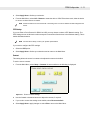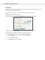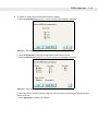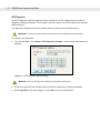
1
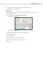
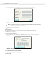
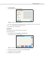
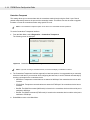
Symbol PD8700 Series
FPE32 Configuration Guide
Symbo PD8700 Series
FPE32 Configuration Guide
72E-86296-01
Revision A
November 2006
ii
PD8700 Series Configuration Guide
© 2006 by Symbol Technologies, Inc. All rights reserved.
No part of this publication may be reproduced or used in any form, or by any electrical or mechanical means,
without permission in writing from Symbol. This includes electronic or mechanical means, such as
photocopying, recording, or information storage and retrieval systems. The material in this manual is subject to
change without notice.
The software is provided strictly on an “as is” basis. All software, including firmware, furnished to the user is on
a licensed basis. Symbol grants to the user a non-transferable and non-exclusive license to use each software
or firmware program delivered hereunder (licensed program). Except as noted below, such license may not be
assigned, sublicensed, or otherwise transferred by the user without prior written consent of Symbol. No right to
copy a licensed program in whole or in part is granted, except as permitted under copyright law. The user shall
not modify, merge, or incorporate any form or portion of a licensed program with other program material, create
a derivative work from a licensed program, or use a licensed program in a network without written permission
from Symbol. The user agrees to maintain Symbol’s copyright notice on the licensed programs delivered
hereunder, and to include the same on any authorized copies it makes, in whole or in part. The user agrees not
to decompile, disassemble, decode, or reverse engineer any licensed program delivered to the user or any
portion thereof.
Symbol reserves the right to make changes to any software or product to improve reliability, function, or design.
Symbol does not assume any product liability arising out of, or in connection with, the application or use of any
product, circuit, or application described herein.
No license is granted, either expressly or by implication, estoppel, or otherwise under any Symbol
Technologies, Inc., intellectual property rights. An implied license only exists for equipment, circuits, and
subsystems contained in Symbol products.
Symbol, Spectrum One, and Spectrum24 are registered trademarks of Symbol Technologies, Inc. Bluetooth is
a registered trademark of Bluetooth SIG. Microsoft, Windows and ActiveSync are either registered trademarks
or trademarks of Microsoft Corporation. Other product names mentioned in this manual may be trademarks or
registered trademarks of their respective companies and are hereby acknowledged.
Symbol Technologies, Inc.
One Symbol Plaza
Holtsville, New York 11742-1300
http://www.symbol.com
iii
Revision History
Changes to the original manual are listed below:
Change
-01 Rev A
Date
11/2006
Description
First Release Version
(Hypercom Rev. F)
iv
PD8700 Series Configuration Guide
Table of Contents
Revision History ............................................................................................................. iii
About This Guide
Introduction ...................................................................................................................
Chapter Descriptions.....................................................................................................
Notational Conventions .................................................................................................
Related Documents.......................................................................................................
Service Information .......................................................................................................
Global Customer Interaction Center........................................................................
iii
iii
iv
v
v
v
Chapter 1: Requirements
Introduction .................................................................................................................. 1-1
FPE32 Overview .......................................................................................................... 1-1
FPE32 Requirements ................................................................................................... 1-2
Chapter 2: FPE32 Configuration
Introduction ..................................................................................................................
Configuring FPE32 .......................................................................................................
Communication Interfaces .....................................................................................
RS232 ..............................................................................................................
10-BaseT Ethernet ...........................................................................................
USB Port ..........................................................................................................
Connecting the Terminal ........................................................................................
Accessing the Menu System ..................................................................................
Accessing the Menu System from a Closed Screen ........................................
Accessing the Menu System on Restart ..........................................................
Changing the Password .........................................................................................
Changing the Password Using the FPE-Sim Application .................................
Changing the Password Using the FPE Interface ............................................
Main Menu .............................................................................................................
Setup Menu ............................................................................................................
Application Mode ..............................................................................................
ECR Port ..........................................................................................................
Network ............................................................................................................
Contrast ............................................................................................................
External PIN Pad ..............................................................................................
HTTP Diagnostics ............................................................................................
Screen Saver ....................................................................................................
2-1
2-1
2-1
2-1
2-1
2-1
2-2
2-3
2-3
2-4
2-4
2-4
2-4
2-5
2-5
2-6
2-7
2-10
2-11
2-12
2-14
2-15
ii
PD8700 Series Configuration Guide
HTMS Connection ............................................................................................. 2-16
Set Date and Time ............................................................................................ 2-17
Diagnostics Menu .................................................................................................... 2-17
Card Reader (Swipe or Contactless) ................................................................ 2-18
Keypad .............................................................................................................. 2-18
M/S Encryption .................................................................................................. 2-19
DUKPT Encryption ............................................................................................ 2-20
Exception Log ................................................................................................... 2-21
Contactless Transparent ................................................................................... 2-22
Contactless Firmware Version .......................................................................... 2-23
M/S Keys ........................................................................................................... 2-23
DUKPT Keys ..................................................................................................... 2-24
Util Menu ................................................................................................................. 2-24
Files ................................................................................................................... 2-25
Setup ................................................................................................................. 2-26
Hardware Configuration .................................................................................... 2-26
Download .......................................................................................................... 2-27
Calibrate ............................................................................................................ 2-32
Restart ............................................................................................................... 2-32
About This Guide
Introduction
This guide explains how to configure FPE32 (Forms Processing Engine) so that you can load and display
images you created in FormBuilder onto a PD8700 series terminal.
This guide is intended for network administrators, operators, or those who configure terminals.
IMPORTANT This guide includes information about the Symbol PD8700 series terminals, Symbol OEM products
from Hypercom Corporation.
Any references in this guide to Hypercom Corporation, Hypercom logo, Hypercom file names and
file paths, Hypercom software and terminals reflect hardware and software manufactured by
Hypercom Corporation for Symbol Technologies, Inc.
Chapter Descriptions
Topics covered in this guide are as follows:
•
Chapter 1, Requirements provides an overview of FPE32 and the hardware and software requirements
of the application.
•
Chapter 2, FPE32 Configuration explains how to install FPE32 to load and display images created in
FormBuilder onto a PD8700 or PD8705 terminal.
iv
PD8700 Series Configuration Guide
Notational Conventions
The following conventions are used in this document:
•
Using a mouse:
- This document assumes the use of a mouse or some other pointing device to move within and
among windows and dialog boxes. When instructions include clicking an item, it means use the
mouse to move the cursor onto the desired item. Click the mouse button to highlight the item or
cause an action to occur.
•
Italics are used to highlight the following:
- Chapters and sections in this and related documents
- Drop-down list and list box names
- Check box and radio button names
- Icons on a screen.
•
Bold text is used to highlight the following:
- Names of buttons
- Typing in text boxes
- Selecting from lists
- Names of windows
- Dialog box components.
•
bullets (•) indicate:
- Action items
- Lists of alternatives
- Lists of required steps that are not necessarily sequential
•
Sequential lists (e.g., those that describe step-by-step procedures) appear as numbered lists.
•
Special icons:
NOTE
Notes contain neutral or positive information supplementing the main text. It is often information that
applies only to special cases.
IMPORTANT Important statements draw attention to information crucial to using the product successfully. Pay
special attention to Important statements.
CAUTION
WARNING!
Cautions advise that a negative result, such as a loss of data, may occur.
Warnings provide information that is essential to the safety of the user, the
equipment, or both. Failure to do as instructed may result in physical damage.
About This Guide
v
Related Documents
For the latest version of this and all payment solution guides go to:http://www.symbol.com/manuals.
Service Information
For service information, warranty information, technical assistance or problems with the equipment, contact the
regional Symbol Global Customer Interaction Center. Before calling, have the model number, serial number
and several bar code symbols at hand.
Call the Global Customer Interaction Center from a phone near the scanning equipment so that the service
person can try to troubleshoot the problem. If the equipment is found to be working properly and the problem is
reading bar codes, the Support Center will request samples of the bar codes for analysis at our plant.
If the problem cannot be solved over the phone, it may be necessary to return the equipment for servicing. If
that is necessary, the Global Customer Interaction Center will provide specific directions.
NOTE
Symbol Technologies is not responsible for any damages incurred during shipment if the approved
shipping container is not used. Shipping the units improperly can possibly void the warranty. If the original
shipping container was not kept, contact Symbol to have another sent.
If the Symbol product was purchased from a Symbol Business Partner, contact that Business Partner for
service.
Global Customer Interaction Center
The addresses and telephone numbers below are provided for you convenience. However, this information
can change due to telephone provider updates. For the most up-to-date contact number information, visit:
www.symbol.com/contactsupport for a Customer Interaction Center in your area.
Country/Region
Address
Telephone
United States
Symbol Technologies, Inc.
One Symbol Plaza
Holtsville, New York 11742-1300
1-800-653-5350
Canada
Symbol Technologies Canada, Inc.
5180 Orbitor Drive
Mississauga, Ontario, Canada L4W 5L9
1-866-416-8545 (Inside Canada)
905-629-7226 (Outside Canada)
United Kingdom
Symbol Technologies
Symbol Place
Winnersh Triangle, Berkshire RG41 5TP
United Kingdom
0800 328 2424 (Inside UK)
+44 118 945 7529 (Outside UK)
Asia/Pacific
Symbol Technologies Asia, Inc.
(Singapore Branch)
230 Victoria Street #12-06/10
Bugis Junction Office Tower
Singapore 188024
Tel: +65-6796-9600
Fax: +65-6337-6488
vi
PD8700 Series Configuration Guide
Country/Region
Address
Telephone
Australia
Symbol Technologies Pty. Ltd.
432 St. Kilda Road
Melbourne, Victoria 3004
1-800-672-906 (Inside Australia)
+61-3-9866-6044 (Outside Australia)
Österreich/Austria
Symbol Technologies Austria GmbH
Prinz-Eugen Strasse 70 / 2.Haus
1040 Vienna, Austria
01-5055794-0 (Inside Austria)
+43-1-5055794-0 (Outside Austria)
Danmark/Denmark
Symbol Technologies AS
Dr. Neergaardsvej 3
2970 Hørsholm
7020-1718 (Inside Denmark)
+45-7020-1718 (Outside Denmark)
Europe/Mid-East
Distributor
Operations
Contact your local distributor or call +44 118
945 7360
Suomi/Finland
Oy Symbol Technologies
Kaupintie 8 A 6
FIN-00440 Helsinki, Finland
9 5407 580 (Inside Finland)
+358 9 5407 580 (Outside Finland)
France
Symbol Technologies France
Centre d'Affaire d'Antony
3 Rue de la Renaissance
92184 Antony Cedex, France
01-40-96-52-21 (Inside France)
+33-1-40-96-52-50 (Outside France)
Deutschland/
Germany
Symbol Technologies GmbH
Waldstrasse 66
D-63128 Dietzenbach, Germany
6074-49020 (Inside Germany)
+49-6074-49020 (Outside Germany)
Italia/Italy
Symbol Technologies Italia S.R.L.
Via Cristoforo Columbo, 49
20090 Trezzano S/N Navigilo
Milano, Italy
2-484441 (Inside Italy)
+39-02-484441 (Outside Italy)
Latin America
Sales Support
2730 University Dr.
Coral Springs, FL 33065 USA
1-800-347-0178 (Inside United States)
+1-954-255-2610 (Outside United States)
954-340-9454 (Fax)
México/Mexico
Symbol Technologies Mexico Ltd.
Torre Picasso
Boulevard Manuel Avila Camacho No 88
Lomas de Chapultepec CP 11000
Mexico City, DF, Mexico
5-520-1835 (Inside Mexico)
+52-5-520-1835 (Outside Mexico)
Nederland/
Netherlands
Symbol Technologies
Kerkplein 2, 7051 CX
Postbus 24 7050 AA
Varsseveld, Netherlands
315-271700 (Inside Netherlands)
+31-315-271700 (Outside Netherlands)
About This Guide
Country/Region
Address
Telephone
Norge/Norway
Symbol’s registered and mailing address:
Symbol Technologies Norway
Hoybratenveien 35 C
N-1055 OSLO, Norway
Symbol’s repair depot and shipping
address:
Symbol Technologies Norway
Enebakkveien 123
N-0680 OSLO, Norway
+47 2232 4375
South Africa
Symbol Technologies Africa Inc.
Block B2
Rutherford Estate
1 Scott Street
Waverly 2090 Johannesburg
Republic of South Africa
11-809 5311 (Inside South Africa)
+27-11-809 5311 (Outside South Africa)
España/Spain
Symbol Technologies S.L.
Avenida de Bruselas, 22
Edificio Sauce
Alcobendas, Madrid 28108
Spain
91 324 40 00 (Inside Spain)
+34 91 324 40 00 (Outside Spain)
Fax: +34.91.324.4010
Sverige/Sweden
“Letter” address:
Symbol Technologies AB
Box 1354
S-171 26 SOLNA
Sweden
Switchboard: 08 445 29 00 (domestic)
Call Center: +46 8 445 29 29 (international)
Support E-Mail:
[email protected]
Visit/shipping address:
Symbol Technologies AB
Solna Strandväg 78
S-171 54 SOLNA
Sweden
vii
viii
PD8700 Series Configuration Guide
Chapter 1
Requirements
Chapter 1
Chapter 1 Requirements
Introduction
This chapter provides an overview of FPE32 and the hardware and software requirements of the application.
FPE32 Overview
This C++ application provides the features necessary for processing transactions in a standard and
configurable product. Using custom forms as overlays to FPE32, you can have the look and feel you want and
the functionality you need to deploy applications quickly without having to write a single line of code.
To utilize FPE32, you simply make calls (using the detailed FPE Interface Specification) and you get the results
you requested. No payment terminal code to write means a time savings of 8 to 12 weeks (typical time to
develop in C++). Sample code is available to handle returned data (such as a signature data block).
FPE32 also supports customer activation mode. This enables the terminal to gather information (such as card
swipe, PIN entry, frequent shopper card, etc.) while the order is being processed. When requested by the ECR,
the information is then provided.
Some of the standard functionality of FPE32 include:
•
Reading and parsing track data (1,2,3 all)
•
Multiple advertising support
•
Signature Capture
•
Multiple language
•
Surveys
•
Frequent Shopper programs
•
Biometrics
•
SmartCard
1-2
PD8700 Series Configuration Guide
FPE32 Requirements
The following list identifies the hardware needed to install and use FPE32:
•
Symbol PD8700 series terminal
•
RS232 cable for connection between Host PC and terminal
•
Host PC running Win32 OS with:
- Minimum Pentium® 2 with 64 MB RAM
- Windows 2000
•
Other Host PC to terminal cables, if you are running other that the standard RS232:
- RS232 cable
- Ethernet cable
- USB cable
The following list identifies the software needed to fully implement FPE32:
•
FPE32 terminal software
•
WinStream, FPELoader, or Hypercom Terminal Management Services (HTMS)
Chapter 2
FPE32 Configuration
Chapter 2
Chapter 2 FPE32 Configuration
Introduction
This chapter explains how to install FPE32 (Forms Processing Engine) and run FPE32.
Configuring FPE32
Several steps are required to install and run FPE32. These steps must be performed in the following order:
1.
Connect the terminal to the Host PC.
2.
Download the initial load of the FPE32 software into the terminal using WinStream, FPELoader, or
Hypercom Terminal Management Services (HTMS).
3.
Configure and verify the terminal communication format.
Communication Interfaces
The communication interfaces for the terminal are:
RS232
The terminal supports one standard RS232 port that can also have power.
NOTE
A specific cable must be used for communication. Refer to the Symbol support site for the appropriate
cable part number and revision.
10-BaseT Ethernet
10-BaseT ethernet support has been integrated directly into the units so it does not require a peripheral card. It
also incorporates a dual port mini-hub that allows the terminal to use existing 10BaseT UTP wiring.
USB Port
The terminal supports one client USB 1.1 port. A USB hub may be used to connect the terminal to multiple
clients. The USB cable emulates a COM Port and will not automatically recognized by your PC.
2-2
PD8700 Series Configuration Guide
Connecting the Terminal
This section enables you to connect the terminal to a host PC or network hub for communication with an ECR.
To connect the terminal:
1.
Connect the terminal with either RS232 cable, USB cable, or Ethernet cable.
2.
If your terminal is not powered by the RS232 cable, connect the power cord plug to a grounded power
outlet and insert the round end of the cord into the power connector. Twist clockwise to lock the cord to the
terminal.
Reset button
Ethernet
connector
USB
connector
Power connector
(if RS232
supplies power,
device may not
have power
connector)
RS232
connector
Figure 2-1 Terminal connections
FPE32 Configuration
2-3
Accessing the Menu System
Determine your next step:
•
To access the menu system from a closed screen, continue with Accessing the Menu System from a Closed Screen,
below.
•
To access the menu system from the terminal’s first screen as the terminal restarts, continue with Accessing the
Menu System on Restart on page 2-4.
Accessing the Menu System from a Closed Screen
To access the menu system from a closed screen:
1.
Use the stylus or your finger to tap the top corners of the screen in a Left - Right - Left pattern as displayed
below.
IMPORTANT This action needs to be performed on a closed screen.
Tap in this pattern:
LEFT, RIGHT, LEFT
Figure 2-2 Accessing the Main Menu
The following screen is displayed:
Figure 2-3 Entering the password
2.
Using the keyboard, enter the password.
3.
Select Enter. If the password is valid, the Main Menu is displayed. If the password is not valid, you will be
prompted to re-enter the password. See your sales representative for the default password.
2-4
PD8700 Series Configuration Guide
Accessing the Menu System on Restart
IMPORTANT The menu system can be accessed from the terminal’s first screen on restart. However, if you do not
press the Setup button within several seconds, the FPE32 software will display the closed screen,
and then you must follow the previous step-by-step procedure to access the menu system.
To access the menu system on restart:
1.
As the initial FPE screen is displayed, press the blue Setup button centered toward the bottom of the
screen. The password screen, as shown above in Figure 2-3, is displayed.
2.
Using the keyboard, enter the password.
3.
Select Enter. If the password is valid, the Main Menu is displayed. If the password is not valid, you will be
prompted to re-enter the password.
Changing the Password
Determine your next step:
•
On the password screen, there are two ways to change the password. Continue with either Changing the Password
Using the FPE-Sim Application or Changing the Password Using the FPE Interface, below.
•
If FPE32 does not have an active password screen, continue with Main Menu on page 2-5.
Changing the Password Using the FPE-Sim Application
The FPE-Sim application is included on the FPE32 Developer’s Toolkit CD. To change the password using the
FPE-Sim application:
1.
Open FPE-Sim and ensure that the application is connected to the terminal.
2.
From the Global tab, enter the new password in the lower right corner.
3.
Select Set Password.
4.
Select Restart Terminal and verify the password change after system restarts.
For more information on FPE-Sim, see the Symbol FPE-Sim Quick Reference Guide.
OR
Changing the Password Using the FPE Interface
To change the password using the FPE interface:
When writing the FPE interface, the ‘p’ command can be sent to the ECR to change the password, e.g.
<FS>p<FS>PWtest<Data>.
NOTE
It is suggested that you change the password on the terminal.
FPE32 Configuration
2-5
Main Menu
The Main Menu screen is shown below in Figure 2-4.
Figure 2-4 Main Menu
IMPORTANT The terminal must be restarted to apply any changes made in the configuration menu. Remember to
use the Util > Restart to restart the device and pick up any changes.
Setup Menu
The setup and configuration is done from the terminal’s setup options screen as shown below:
Figure 2-5 Setup options
2-6
PD8700 Series Configuration Guide
Application Mode
PD8700 series terminals support three PIN Pad protocols: FPE, SCAT, and EFT.
FPE (Forms Processing Engine) is a protocol that includes commands to request PIN, MSR and contactless
track data, signature capture, and other information including cash back amount and phone number.
The main command, FormRequest, displays a specified form on the PIN Pad and can have additional
parameters that specify PIN encryption type, signature capture resolution, global prompts, etc. FPE protocol
also supports so-called customer action mode. In this mode, the PIN Pad automatically displays a sequence of
forms (e.g. swipe form, tender selection form, PIN form, or wait form) gathering transaction information. In this
mode, ECR periodically polls the PIN Pad to monitor its status and to get the data. Symbol OPOS
implementation uses FPE protocol.
SCAT is a PIN Pad protocol used to request PIN, MSR and contactless track data, signature capture, and
other information like cash back amount or phone number. It has specific commands for each type of
information request, e.g. GetPIN, GetMSR, GetSignature etc.
EFT is a PIN Pad protocol used by IBM cash registers. ECR initiates the transaction and the PIN Pad displays
run through a number of forms requesting tender type, PIN, and other information as configured in the EFT
configuration file on the PIN pad.
To configure the application mode for the terminal:
1.
From the Main Menu, select Setup > Application Mode. The following screen is displayed:
Figure 2-6 Selecting the Application Mode
2.
Select the application mode you are using.
3.
Select Apply Now to finalize the setting.
FPE32 Configuration
ECR Port
The ECR port allows terminal access through either a Serial line, TCP/IP, or USB connection.
To configure the ECR port:
1.
From the Main Menu, select Setup > ECR Port.
The following screen is displayed:
Figure 2-7 Select ECR port
2.
Identify your connection type and then determine your next step:
- To configure a Serial line connection, continue with Serial Line Connection on page 2-7.
- To configure a TCP/IP connection, continue with TCP/IP ECR Connection on page 2-9.
- To configure a USB connection, continue with USB Connection on page 2-9.
Serial Line Connection
To configure the serial connection:
1.
Select Serial line by selecting the radio button to the left of the Connect to ECR screen
(Figure 2-7).
2.
Select the Next Screen arrow [>>].
2-7
2-8
PD8700 Series Configuration Guide
The following screen is displayed:
Figure 2-8 Selecting the Baud Rate for ECR Serial connection
1.
Select the baud rate by selecting the appropriate radio button to the left.
2.
Select the Next Screen arrow [>>].
The following screen is displayed:
Figure 2-9 Selecting the Parity, Data Bits, Stop Bits, and Flow Control for Serial ECR connection
3.
Select the values for Parity, Data bits, Stop bits, and Flow Control by selecting the appropriate radio
buttons to the left.
4.
Select Apply Now to finalize your changes.
5.
Check the serial line connection using FPE-Sim. For more information on FPE-Sim, see the FPE-Sim
Quick Reference Guide included on the FPE32 Developer’s Toolkit CD.
FPE32 Configuration
2-9
TCP/IP ECR Connection
To configure the TCP/IP connection:
IMPORTANT You must know either the IP Address and port used to communicate with the ECR or obtain an IP
address using DHCP.
1.
From the Connect to ECR screen (Figure 2-7), select the TCP/IP Connection by selecting the radio button
to the left.
2.
Select the Next Screen arrows [>>].
3.
Enter the IP Address and port used to communicate with the ECR.
Figure 2-10 TCP/IP ECR connection
4.
Select Apply Now to finalize your selection.
5.
Check the TCP/IP connection using FPE-Sim. For more information on FPE-Sim, see the
FPE-Sim Quick Reference Guide included on the FPE32 Developer’s Toolkit CD.
6.
Obtain the IP address using DHCP. See Ethernet Settings on page 2-10 for more information on DHCP.
USB Connection
If the USB connection is selected, the USB cable emulates a COM port and will be automatically recognized by
your PC. See the FPE32 Developer’s Toolkit CD for the RS232 to USB driver.
To configure the USB connection:
1.
From the Main Menu, select Setup > ECR Port > USB.
2.
Select Apply Now to finalize your changes.
3.
Check the USB connection using FPE-Sim. For more information on FPE-Sim, see the
FPE-Sim Quick Reference Guide included on the FPE32 Developer’s Toolkit CD.
2 - 10 PD8700 Series Configuration Guide
Network
Select this option to configure the Device Network Setting using either Ethernet or PPP.
To configure the device network:
From the Main Menu, select Setup > Network.
1.
The following screen is displayed:
Figure 2-11 Device Network Settings
Determine your next step:
•
To configure an ethernet connection, continue with Ethernet Settings on page 2-10.
•
To configure a PPP connection, continue with PPP Settings on page 2-11.
Ethernet Settings
To configure the Ethernet connection:
1.
Select the Ethernet option and then select the Next Screen arrows [>>]. The following screen is
displayed.
Figure 2-12 Ethernet settings
2.
If you know your IP Address, Subnet Mask and Router information, enter the information. If not, select the
DHCP option to allow a DHCP server to automatically assign this information.
FPE32 Configuration
2 - 11
3.
Select Apply Now to finalize your selection.
4.
From the Main Menu, select Util > Restart to restart the device. If DHCP has been used, allow the device
to move to a closed screen on restart.
NOTE
DHCP information can be found the Util > HW Config menu once an IP address has been assigned to the
device.
PPP Settings
If you use Point to Point Protocol for RS232 or USB, you may choose to select a PPP Network setting. The
PPP Settings screen is left blank to allow anonymous connections from devices in the Windows setting. This is
default Windows behavior.
NOTE
For RAS Server Setup, contact your Symbol representative.
If you need to configure the PPP settings:
1.
Select the PPP option.
2.
Select Apply Now to finalize your selections and to return to the Main Menu.
Contrast
This setting allows the screen’s contrast to be adjusted or restored to default.
To set the screen contrast:
1.
From the Main Menu, select Setup > Contrast. A screen similar to the following is displayed:
Figure 2-13 Screen contrast settings
2.
Use the forward or backward arrows to adjust the contrast, if required.
3.
If you need to restore the settings to the default, select Revert to default.
4.
Select Apply Now to apply changes or select Exit to return to the Main Menu.
2 - 12 PD8700 Series Configuration Guide
External PIN Pad
Customers are prompted to enter their PIN using an external PIN Pad. The external PIN Pad settings are used
to auto-detect and activate an external PIN pad.
NOTE
To use an external PIN Pad, you must have a Y cable that splits the RS232 cable
To configure the External PIN Pad connection:
1.
From the Main Menu, select Setup > External PIN Pad. The following screen is displayed:
Figure 2-14 External PIN Pad settings
2.
Ensure the External PIN Pad is connected to the terminal using a Y cable.
3.
To have the terminal automatically detect the PIN Pad’s serial connection:
a. Select Auto Detect. A “PIN Pad detected” message is displayed.
b. Select Use PIN Pad checkbox.
c. Select Apply Now to finalize the settings.
FPE32 Configuration
4.
2 - 13
To confirm or change the serial PIN Pad connection settings:
a. Select the Next Screen arrows [>>]. A screen similar to the following is displayed:
Figure 2-15 Baud Rate settings
b. Select the Baud rate by selecting the appropriate radio button to the left.
c. Select the Next Screen arrows [>>]. A screen similar to the following is displayed:
Figure 2-16 Parity, Data Bits, Stop Bits, and Flow Control settings
d. Select the values for Parity, Data bits, Stop bits, and Flow Control by selecting the appropriate radio
buttons to the left.
e. Select Apply Now to finalize your changes.
2 - 14 PD8700 Series Configuration Guide
HTTP Diagnostics
The HTTP Diagnostic address settings are used to configure the TCP/IP address and port number for
diagnostic message transmission. The message is sent in the format of an HTTP request to the specified
address and port.
The diagnostic message includes the IP Address and Port number of the requesting terminal.
IMPORTANT If not using the HTTP Diagnostic settings, leave the IP Address and Port number blank.
To configure HTTP diagnostics:
1.
From the Main Menu, select Setup > HTTP diagnostic message. A screen similar to the following is
displayed:
Figure 2-17 HTTP Diagnostic address settings
IMPORTANT At this time, the diagnostic message only supports the global.cfg file.
2.
Using the keypad, enter the IP address and port number for diagnostic message transmission.
3.
Select Apply Now if you made changes, or select Exit to return to the Main Menu.
FPE32 Configuration
2 - 15
Screen Saver
The Screen Saver turns the screen to black after the set period of inactivity, extending the life of the screen.
The screen returns to its activated mode when any button is pressed or if the screen is touched.
NOTE
During the first application load, the Screen Saver option is checked automatically.
To set the Screen Saver:
1.
From the Main Menu, select Setup > Screen Saver. A screen similar to the following is displayed:
Figure 2-18 Screen saver settings
2.
Select the Use Screen Saver checkbox or ensure that it is selected if you require the screen saver to be
used.
3.
If you need to change the number of minutes before the time-out, use the keyboard on the screen to set
your desired time-out in minutes between 1 and 30.
a. Select Clear to clear the time-out in minutes field.
b. Select Enter to display the number of minutes in the time-out window.
NOTE
4.
If using FPE, time-out defaults to thirty minutes of inactivity. If using SCAT, time-out defaults to twenty
minutes of inactivity.
Select Apply Now to finalize your selection.
2 - 16 PD8700 Series Configuration Guide
HTMS Connection
Hypercom Terminal Management Services (HTMS) is used to load Optimum terminal applications and packing
lists through an ethernet connection. To use HTMS, you must first install the HTMS application, configure
Optimum terminals for TCP/IP, and configure the terminal database.
See the Terminal Management Services User Guide for more information on HTMS.
To allow a connection to HTMS:
1.
From the Main Menu, select Setup > HTMS Conn. A screen similar to the following is displayed:
Figure 2-19 HTMS Connection settings
2.
Select the Allow connection to HTMS checkbox.
3.
Using the keypad on the screen, set the IP Address and port used to communicate with HTMS.
4.
Select Apply Now to finalize your selection.
5.
Restart the device. On restart the connection is made to HTMS.
FPE32 Configuration
2 - 17
Set Date and Time
To set the date and time:
1.
From the Main Menu, select Setup > Set Date. A screen similar to the following is displayed:
Figure 2-20 Set Date and Time settings
2.
To set the date, use the keyboard on the screen to set the date in the mm/dd/yy fields.
3.
To set the time, use the keyboard on the screen to set the desired time in the hh:mm:ss fields.
4.
Select Apply Now to finalize your selection.
Diagnostics Menu
The terminal has several diagnostic options built into the terminal that allow you to test, view, or verify data
stored in the system.
Figure 2-21 Diagnostics options screen
2 - 18 PD8700 Series Configuration Guide
Card Reader (Swipe or Contactless)
This diagnostic tool allows you to view track data from magnetic swipe or contactless cards.
To use the Card Reader tool:
1.
From the Main Menu, select Diagnostics > Card Reader.
A screen similar to the following is displayed:
Figure 2-22 Card Reader settings
2.
Swipe the magnetic swipe or contactless card to view the information stored on the tracks.
3.
Select Clear All to swipe another card.
4.
Select Exit to return to the Main Menu.
Keypad
This diagnostic tool presents a QWERTY keyboard that allows you to test the screen’s acceptance of
alpha-numeric inputs.
To use the Keypad tool:
1.
From the Main Menu, select Diagnostics > Keypad.
The following screen is displayed:
Figure 2-23 Keypad settings
FPE32 Configuration
2.
Select characters on the keyboard to test the screen’s acceptance of inputs.
3.
Select Exit to return to the Main Menu.
M/S Encryption
This diagnostic tool allows the user to enter data and to generate a PIN Block for a Master Session Key.
To use the M/S Encryption tool:
1.
From the Main Menu, select Diagnostics > M/S Encryption.
The following screen is displayed:
Figure 2-24 M/S Encryption settings
NOTE
All fields must be entered before you can continue with Step 6.
2.
Enter the Account number.
3.
Enter the Master Key.
4.
Enter the Working Key (alpha and numeric allowed).
NOTE
5.
T he Working Key field length must be either 16 or 32.
Enter the PIN.
2 - 19
2 - 20 PD8700 Series Configuration Guide
6.
Select Encrypt Now to create a PIN Block. A screen similar to the following is displayed:
Figure 2-25 M/S Encryption information
NOTE
7.
If the PIN Block encryption fails, an “Encryption failed” message is displayed on the next screen. Usually
this message indicates that the key is not injected.
Select Exit to return to the Main Menu.
DUKPT Encryption
This diagnostic tool allows the user to enter data and to generate a PIN Block for a DUKPT Key.
Multi-DUKPT is also supported.
To use the DUKPT Encryption tool:
1.
From the Main Menu, select Diagnostics > DUKPT Encryption. A screen similar to the following is
displayed:
Figure 2-26 DUKPT Encryption settings
2.
Use the keypad to enter the Account number.
3.
Enter the DUKPT Key Index number. The default is 12.
4.
Enter the PIN.
FPE32 Configuration
5.
Select Encrypt Now.
A screen similar to the following is displayed:
Figure 2-27 DUKPT Encryption information
NOTE
6.
If the encryption fails, an “Encryption failed” message is displayed on the next screen. Usually this
message indicates that the key is not injected.
Select Exit to return to the Main Menu.
Exception Log
This diagnostic tool shows a list of exceptions on the terminal.
To use the Exception Log:
1.
From the Main Menu, select Diagnostics > Exception Log.
A screen similar to the following is displayed:
Figure 2-28 Exception Log settings
2.
Use the stylus to select an exception and then select Read or Save.
3.
To clear the Exception Log, select Clear.
4.
Select Exit to return to the Main Menu.
2 - 21
2 - 22 PD8700 Series Configuration Guide
Contactless Transparent
This setting allows you to communicate with the contactless reader directly using the Serial 1 port. Data is
passed transparently between the port and the contactless reader. This feature can also be used to upgrade
firmware or to test the contactless reader using special PC tools.
NOTE
The Contactless Transparent option is not used in non-contactless terminal operations.
To set the Contactless Transparent interface:
1.
From the Main Menu, select Diagnostics > Contactless Transparent.
The following screen is displayed:
Figure 2-29 Contactless Transparent settings
NOTE
2.
If you are not using a contactless device, the screen will display “Contactless not found”.
The Contactless Transparent interface supports four baud rate options. It is suggested that you manually
select the baud rate for your terminal. After configuring the baud rate, it can be switched automatically by
sending a command to the contactless device.
- 9600 Baud: Transparent communications are started at 9600 bps if the contactless device has valid
firmware.
- 57600 Baud: Transparent communications are started at 57600 bps if the contactless device has no
firmware.
- BAUD0: The BAUD0 command (9600 mode) is issued to the contactless device and the serial port is
switched to 9600 bps.
- BAUD3: The BAUD3 command (57600 mode) is issued to the contactless device and the serial port is
switched to 57600 bps.
3.
Select Exit to return to the Main Menu.
FPE32 Configuration
2 - 23
Contactless Firmware Version
If you are using a contactless device, this diagnostic tool allows you to view the current firmware version.
To view the contactless firmware version:
1.
From the Main Menu, select Diagnostics > Contactless Firmware Version.
If you are using a contactless device, the version of the installed firmware will be displayed. If you are not
using a contactless device, the screen will display “Contactless not found”.
The following screen is displayed:
Figure 2-30 Contactless Firmware Version
M/S Keys
This diagnostic tool shows the index of the Master Session key.
To view Master Session index keys:
1.
From the Main Menu, select Diagnostics > M/S Keys.
A screen similar to the following is displayed:
Figure 2-31 M/S Index Keys information
2.
Select Exit to return to the Main Menu.
2 - 24 PD8700 Series Configuration Guide
DUKPT Keys
This diagnostic tool shows the index of the DUKPT key.
To view DUKPT index keys:
1.
From the Main Menu, select Diagnostics > DUKPT Keys.
A screen similar to the following is displayed:
Figure 2-32 DUKPT Index Keys information
2.
Select Exit to return to the Main Menu.
Util Menu
The terminal has several utility options built into the terminal that allow you to download and view loaded files
and calibrate and restart the terminal.
Figure 2-33 Util options screen
FPE32 Configuration
2 - 25
Files
From this option you can view all the files loaded into the terminal from a packing list or key download. You can
also delete all the files in preparation for a new packing list download.
To view the files loaded into the terminal:
1.
From the Main Menu, select Util > Files. An example of a screen is shown below:
Figure 2-34 Terminal file system screen
From this screen you can view all the files loaded into the terminal from a packing list. Use the scroll bar to
move through the list. The amount of space used and the space available is also displayed on the right
side of the screen.
2.
If you need to delete a file from the list, select the file name and select Delete file.
3.
If you need to delete all files in preparation for a new packing list download, select Delete all.
4.
Select Exit to return to the Main Menu.
2 - 26 PD8700 Series Configuration Guide
Setup
This option allows you to view the serial number and the MAC Address for the terminal.
To view the serial number or MAC address for the terminal:
1.
From the Main Menu, select Util > Setup.
The following screen is displayed:
Figure 2-35 Serial number and MAC address screen
2.
View the serial number or the MAC address.
3.
Select Exit to return to the Main Menu.
Hardware Configuration
Use this option to get a quick snapshot of the terminal.
To view the hardware configuration:
1.
From the Main Menu, select Util > HW Config.
The following screen is displayed:
Figure 2-36 Hardware configuration settings
2.
Select Exit to return to the Main Menu.
FPE32 Configuration
Download
Use this option to download keys, applications, and packing lists to the terminal.
To download software to the terminal:
1.
From the Main Menu, select Util > Download.
The following screen is displayed, listing your download options:
Figure 2-37 Download settings
Downloading Keys
NOTE
You need an HKLM device to download keys.
To download new keys to the terminal:
1.
From the Main Menu, select Util > Download > Download Keys.
The following screen is displayed and you are prompted to select the key injection interface:
Figure 2-38 Download Keys settings
2.
Select on the appropriate option. The terminal attempts to download the keys.
3.
Select Exit to return to the Main Menu.
2 - 27
2 - 28 PD8700 Series Configuration Guide
Downloading the Application
Determine your next step:
To download using PPP:
1.
Ensure the application has been copied to the OS folder under \inetpub\ftproot\ or to the configured
location on the server.
2.
From the Main Menu on the device, select Setup > Network. Ensure the device is set to PPP and select
Apply Now.
3.
Select Util > Restart to reboot the device to finalize the PPP selection.
4.
From the Main Menu, select Util > Download > Download Application.
The device beeps continuously as the application downloads.
OR
To download using an Ethernet connection:
The device must have an IP address configured.
1.
To see the assigned IP Address of the device, look under Util > HW Config. If you do not see an address
assigned, go to Setup > Network > Ethernet to either manually insert an address or obtain one using
DHCP. Restart the device to apply the changes and check under Util > HW Config to verify the
IP Address.
2.
Ensure the application has been copied to the OS folder under \inetpub\ftproot\ or to the configured
location on the server.
3.
From the Main Menu, select Util > Download > Download Application.
The device beeps continuously as the application downloads.
Streaming the Application
Before you begin, you need to gather the following information:
•
Host PC COM port number used to download terminal software
•
Host PC baud rate
•
The location of the .txt application file
FPE32 Configuration
2 - 29
To stream the application:
IMPORTANT The ECR port needs to be set prior to these steps.
1.
To set up the terminal, select Util > Download > Stream Application from the Main Menu.
The following screen is displayed, listing your download options:
Figure 2-39 Stream application settings
2.
Select USB or the appropriate baud rate.
The terminal will then instruct you to begin the download at that baud rate and will wait for the download to
begin from the Host PC.
3.
Start the WinStream application on your Host PC.
WinStream is installed with the FPE Interface application. After the FPE Interface application is installed on
your Host PC, select Start > Programs > Hypercom > FPE Interface > WinStream.
The starting WinStream dialog box is displayed:
Figure 2-40 WinStream start dialog box
4.
Select Browse to locate the terminal software.
2 - 30 PD8700 Series Configuration Guide
5.
To configure the port and baud rate, select Settings. The Settings dialog box is displayed.
Figure 2-41 WinStream settings dialog box
6.
Ensure the COM port is set to the port connected on the Host PC and the correct Baud Rate is set.
IMPORTANT Ensure you select the same baud rate here that you did on the terminal screen.
7.
Select OK.
The starting WinStream dialog box re-appears.
8.
Select Start. While the software is downloaded to the terminal, a progress bar displays on both the
terminal screen and the WinStream application. The terminal screen also shows the page that was last
downloaded.
Figure 2-42 WinStream run dialog box
FPE32 Configuration
9.
2 - 31
When the software finishes downloading, as shown in Figure 2-43, select Exit.
Figure 2-43 WinStream download completed dialog box
The WinStream application closes and the terminal is ready to be configured.
Downloading the Packing List
This option is used to load the packing list using ftp.
Determine your next step:
To download using PPP:
1.
Confirm the ECR settings are set to PPP.
2.
Copy the dl folder for the FormBuilder project to ftproot.
3.
Create a packinglist folder under ftproot. The packinglist folder includes a packinglist .txt file. There
is one line in the .txt file, ..\dl.
4.
From the Main Menu on the device, select Util > Download > Packing List.
The device beeps continuously as the packinglist downloads.
5.
Once the download is complete, restart the terminal.
OR
To download using an Ethernet connection:
1.
You must specify the IP Address of the device. This can be done either manually or through a DHCP
connection.
To see the assigned IP Address of the device, look under Util > HW Config. If you do not see an address
assigned, go to Setup > Network to either manually insert an address or obtain one using DHCP. Restart
the device to apply the changes and check under Util > HW Config to verify the IP Address.
2.
Copy the dl folder for the FormBuilder project to ftproot.
3.
Create a packinglist folder under ftproot. The packinglist folder includes a packinglist .txt file. There is
one line in the .txt file, ..\dl.
4.
From the Main Menu, select Util > Download > Packing List.
The device beeps continuously as the packinglist downloads.
5.
Once the download is complete, restart the terminal.
2 - 32 PD8700 Series Configuration Guide
Calibrate
The terminal can be calibrated by using the stylus to touch various points on the screen. Calibration ensures
the preciseness of customer input fields.
To calibrate the screen:
1.
From the Main Menu, select Util > Calibrate.
2.
Use the stylus to touch the targets shown in each corner and at the center of the screen.
The following screen reports whether or not the calibration passed and then restarts the terminal.
Restart
The terminal can be restarted under this menu option.
IMPORTANT The terminal must be restarted through the Util menu if you are applying new changes that must be
loaded at the boot level.
The terminal can also be restarted by pressing in on the small tab in the back right corner, but this
restart method should not be used if you are applying boot level changes. (See Figure 1 on page 3
for the location of the reset button.)
To restart the terminal:
1.
From the Main Menu, select Util > Restart.
The terminal screen goes black and then restarts.
Index
Index
A
D
application
downloading . . . . . . . . . . . . . . . . . . . . . . . . . . . 2-28
mode . . . . . . . . . . . . . . . . . . . . . . . . . . . . . . . . . . 2-6
software, introduction . . . . . . . . . . . . . . . . . . . . . 1-1
streaming . . . . . . . . . . . . . . . . . . . . . . . . . . . . . 2-28
date . . . . . . . . . . . . . . . . . . . . . . . . . . . . . . . . . . . . . 2-17
diagnostics options
card reader . . . . . . . . . . . . . . . . . . . . . . . . . . . . 2-18
choices from screen . . . . . . . . . . . . . . . . . . . . . 2-17
contactless firmware version . . . . . . . . . . . . . . . 2-23
contactless transparent . . . . . . . . . . . . . . . . . . . 2-22
DUKPT encryption . . . . . . . . . . . . . . . . . . . . . . . 2-20
DUKPT keys . . . . . . . . . . . . . . . . . . . . . . . . . . . 2-24
exception log . . . . . . . . . . . . . . . . . . . . . . . . . . . 2-21
HTTP . . . . . . . . . . . . . . . . . . . . . . . . . . . . . . . . . 2-14
keypad . . . . . . . . . . . . . . . . . . . . . . . . . . . . . . . . 2-18
M/S encryption . . . . . . . . . . . . . . . . . . . . . . . . . 2-19
M/S keys . . . . . . . . . . . . . . . . . . . . . . . . . . . . . . 2-23
downloading
application using PPP or RS232 . . . . . . . . . . . . 2-28
available options . . . . . . . . . . . . . . . . . . . . . . . . 2-27
keys . . . . . . . . . . . . . . . . . . . . . . . . . . . . . . . . . . 2-27
packing list . . . . . . . . . . . . . . . . . . . . . . . . . . . . . 2-31
DUKPT
encryption . . . . . . . . . . . . . . . . . . . . . . . . . . . . . 2-20
keys . . . . . . . . . . . . . . . . . . . . . . . . . . . . . . . . . . 2-24
B
bold text . . . . . . . . . . . . . . . . . . . . . . . . . . . . . . . . . . . . iv
bulleted items . . . . . . . . . . . . . . . . . . . . . . . . . . . . . . . . iv
bullets . . . . . . . . . . . . . . . . . . . . . . . . . . . . . . . . . . . . . . iv
C
calibrating terminal . . . . . . . . . . . . . . . . . . . . . . . . . 2-32
card reader . . . . . . . . . . . . . . . . . . . . . . . . . . . . . . . 2-18
caution messages . . . . . . . . . . . . . . . . . . . . . . . . . . . . . iv
changing password
using FPE interface . . . . . . . . . . . . . . . . . . . . . . 2-4
using FPE-Sim application . . . . . . . . . . . . . . . . . 2-4
communication interfaces
ethernet . . . . . . . . . . . . . . . . . . . . . . . . . . . . . . . 2-1
RS232 . . . . . . . . . . . . . . . . . . . . . . . . . . . . . . . . . 2-1
USB port . . . . . . . . . . . . . . . . . . . . . . . . . . . . . . . 2-1
connecting
serial line . . . . . . . . . . . . . . . . . . . . . . . . . . . . . . 2-7
TCP/IP . . . . . . . . . . . . . . . . . . . . . . . . . . . . . . . . 2-9
terminal to host PC or network hub . . . . . . . . . . 2-2
to HTMS . . . . . . . . . . . . . . . . . . . . . . . . . . . . . . 2-16
USB . . . . . . . . . . . . . . . . . . . . . . . . . . . . . . . . . . 2-9
contactless
firmware version . . . . . . . . . . . . . . . . . . . . . . . . 2-23
transparent . . . . . . . . . . . . . . . . . . . . . . . . . . . . 2-22
contrast setting . . . . . . . . . . . . . . . . . . . . . . . . . . . . 2-11
conventions
notational . . . . . . . . . . . . . . . . . . . . . . . . . . . . . . . . iv
customer interaction center . . . . . . . . . . . . . . . . . . . . .2-v
E
ECR port . . . . . . . . . . . . . . . . . . . . . . . . . . . . . . . . . . 2-7
encryption
DUKPT . . . . . . . . . . . . . . . . . . . . . . . . . . . . . . . 2-20
M/S . . . . . . . . . . . . . . . . . . . . . . . . . . . . . . . . . . 2-19
ethernet
integration . . . . . . . . . . . . . . . . . . . . . . . . . . . . . . 2-1
settings . . . . . . . . . . . . . . . . . . . . . . . . . . . . . . . 2-10
exception log . . . . . . . . . . . . . . . . . . . . . . . . . . . . . . 2-21
external PIN pad . . . . . . . . . . . . . . . . . . . . . . . . . . . 2-12
F
files, view loaded on terminal . . . . . . . . . . . . . . . . . . 2-25
FPE32
overview . . . . . . . . . . . . . . . . . . . . . . . . . . . . . . . 1-1
Index - 2
PD8700 Series Configuration Guide
requirements . . . . . . . . . . . . . . . . . . . . . . . . . . . . 1-2
H
hardware configuration . . . . . . . . . . . . . . . . . . . . . . 2-26
HTMS . . . . . . . . . . . . . . . . . . . . . . . . . . . . . . . . . . . 2-16
HTTP diagnostics . . . . . . . . . . . . . . . . . . . . . . . . . . 2-14
R
requirements
software . . . . . . . . . . . . . . . . . . . . . . . . . . . . . . . . 1-2
restarting the terminal . . . . . . . . . . . . . . . . . . . . . . . . 2-32
RS232 port . . . . . . . . . . . . . . . . . . . . . . . . . . . . . . . . . 2-1
S
I
important messages . . . . . . . . . . . . . . . . . . . . . . . . . . .iv
italics . . . . . . . . . . . . . . . . . . . . . . . . . . . . . . . . . . . . . . .iv
K
keypad . . . . . . . . . . . . . . . . . . . . . . . . . . . . . . . . . . .
keys
downloading . . . . . . . . . . . . . . . . . . . . . . . . . . .
DUKPT . . . . . . . . . . . . . . . . . . . . . . . . . . . . . . .
M/S . . . . . . . . . . . . . . . . . . . . . . . . . . . . . . . . . .
2-18
2-27
2-24
2-23
L
log, encryption . . . . . . . . . . . . . . . . . . . . . . . . . . . . . 2-21
M
M/S
encryption . . . . . . . . . . . . . . . . . . . . . . . . . . . . . 2-19
keys . . . . . . . . . . . . . . . . . . . . . . . . . . . . . . . . . . 2-23
MAC address . . . . . . . . . . . . . . . . . . . . . . . . . . . . . . 2-26
main menu
diagnostics options . . . . . . . . . . . . . . . . . . . . . . 2-17
options . . . . . . . . . . . . . . . . . . . . . . . . . . . . . . . . 2-5
setup options . . . . . . . . . . . . . . . . . . . . . . . . . . . . 2-5
utilities options . . . . . . . . . . . . . . . . . . . . . . . . . 2-24
mode, application . . . . . . . . . . . . . . . . . . . . . . . . . . . 2-6
screen saver . . . . . . . . . . . . . . . . . . . . . . . . . . . . . . . 2-15
sequential lists . . . . . . . . . . . . . . . . . . . . . . . . . . . . . . . iv
serial line connection . . . . . . . . . . . . . . . . . . . . . . . . . 2-7
serial number . . . . . . . . . . . . . . . . . . . . . . . . . . . . . . 2-26
service information . . . . . . . . . . . . . . . . . . . . . . . . . . .v, v
setup options
choices from screen . . . . . . . . . . . . . . . . . . . . . . . 2-5
contrast . . . . . . . . . . . . . . . . . . . . . . . . . . . . . . . 2-11
date . . . . . . . . . . . . . . . . . . . . . . . . . . . . . . . . . . 2-17
ethernet . . . . . . . . . . . . . . . . . . . . . . . . . . . . . . . 2-10
HTMS connection . . . . . . . . . . . . . . . . . . . . . . . 2-16
network . . . . . . . . . . . . . . . . . . . . . . . . . . . . . . . 2-10
PIN pad . . . . . . . . . . . . . . . . . . . . . . . . . . . . . . . 2-12
PPP . . . . . . . . . . . . . . . . . . . . . . . . . . . . . . . . . . 2-11
screen saver . . . . . . . . . . . . . . . . . . . . . . . . . . . 2-15
time . . . . . . . . . . . . . . . . . . . . . . . . . . . . . . . . . . 2-17
software requirements . . . . . . . . . . . . . . . . . . . . . . . . 1-2
special icons . . . . . . . . . . . . . . . . . . . . . . . . . . . . . . . . . iv
streaming the application . . . . . . . . . . . . . . . . . . . . . 2-28
T
TCP/IP connection . . . . . . . . . . . . . . . . . . . . . . . . . . . 2-9
terminal
calibrating . . . . . . . . . . . . . . . . . . . . . . . . . . . . . 2-32
restarting . . . . . . . . . . . . . . . . . . . . . . . . . . . . . . 2-32
time . . . . . . . . . . . . . . . . . . . . . . . . . . . . . . . . . . . . . . 2-17
U
N
network settings . . . . . . . . . . . . . . . . . . . . . . . . . . . . 2-10
notational conventions . . . . . . . . . . . . . . . . . . . . . . . . . .iv
note messages . . . . . . . . . . . . . . . . . . . . . . . . . . . . . 2-iv
P
packing list, downloading . . . . . . . . . . . . . . . . . . . . . 2-31
password
changing using FPE interface . . . . . . . . . . . . . . . 2-4
changing using FPE-Sim application . . . . . . . . . 2-4
PIN pad setup . . . . . . . . . . . . . . . . . . . . . . . . . . . . . 2-12
PPP settings . . . . . . . . . . . . . . . . . . . . . . . . . . . . . . 2-11
USB
connection . . . . . . . . . . . . . . . . . . . . . . . . . . . . . . 2-9
port . . . . . . . . . . . . . . . . . . . . . . . . . . . . . . . . . . . . 2-1
utilities options
calibrating . . . . . . . . . . . . . . . . . . . . . . . . . . . . . 2-32
choices from screen . . . . . . . . . . . . . . . . . . . . . . 2-24
downloading application . . . . . . . . . . . . . . . . . . . 2-28
downloading keys . . . . . . . . . . . . . . . . . . . . . . . 2-27
files . . . . . . . . . . . . . . . . . . . . . . . . . . . . . . . . . . 2-25
hardware configuration (HW Config) . . . . . . . . . 2-26
options available at download screen . . . . . . . . 2-27
packing list . . . . . . . . . . . . . . . . . . . . . . . . . . . . . 2-31
restart . . . . . . . . . . . . . . . . . . . . . . . . . . . . . . . . . 2-32
setup . . . . . . . . . . . . . . . . . . . . . . . . . . . . . . . . . 2-26
Index - 3
streaming the application . . . . . . . . . . . . . . . . . 2-28
W
warning messages . . . . . . . . . . . . . . . . . . . . . . . . . . . . iv
Index - 4
PD8700 Series Configuration Guide
Symbol Technologies, Inc.
One Symbol Plaza
Holtsville, New York 11742-1300
http://www.symbol.com
72E-86296-01
Revision A - November 2006