1
Model #: CVDVR900
MPEG-4 Embedded DVR
User Manual
now
you
can
see
www.svat.com
INSTALLATION GUIDELINE
A. Installation Environment
In order to ensure the safety with the DVR product and maximize product performance, please notice the following while/ before you install the product:
i. Only use with AV220V voltage supply, please check with the power supply
with correct voltage before installation. DO NOT USE WITH ANY OTHER
ADAPTER (DO NOT PLUG INTO AC380V HIGH VOLTAGE SUPPLY!)
ii. Away from a humid place or exposure with rain.
iii. DVR should be installin in a horizontal position.
iv. Avoid placing the DVR in a location where electric conductivity is high.
v. Avoid exposure to direct sunlight for prolinged periods and do not store in
areas with extreme temperature conditions.
vi. For the heat transfer and ventilation purposes, locate the DVR at least 15cm
from another object (such as awall) while installing the device.
vii. Avoid placing the DVR near any chemical product. Accidental contact
may harm the device.
viii.Avoid placing the device in areas that are dusty and unkept. Dust may
damage the unit.
ix. Use correct grounding for the DVR device while operating.
B. Other notices
i. Do not operate the device with wet hands.
ii. Keep away from any wet place, fire hazard can occur by short circuit
damage by any liquid dropped to device.
iii. Do not place anything on the top of device;
iv. Use a clean cloth to clean the device. Do not use chemicals to clean the
device.
v. Live voltage does exist while the device is connected to a power supply,
even when the device is not turned on.
vi. Disconnect the DVR when not in use for an extended period.
This device had been certified with the international safety standard.
PRODUCT FUNCTIONS/ FEATURES
• High speed embedded CPS and real time embedded control operation
system are adapted with the product. It provides operation stability, no
hang-up error, more reliability and ease for maintainance.
• Operation with front panel and remote control, menu language also
available in English/Chinese/Simplified Chinese. Security with double
password lock. System management requires authority code in order to
provide safety system.
• Uses a hardware MPEG-4 encoder to provide better streaming quality, it
also supports D1, 1/2D1, CIF resolution, and has an adjustable frame rate
and provides space efficiency with compact video size.
• Video storage using FAT32 format, suitable for 1~4 IDE hard drive
connections, there are 3 types of storage methods in use here: individual,
compound and mixed;
• Provides multi-channel operation, such as 4 channel video/audio input
capture, 2 channel video (monitor and reply) output, with VGA reply
output.
• 4-channels alarm input with programmable setting.
• Time setting to activate recording system with auto switching, system
re-activate after power shut down. Alert system for any video signal loss or
disturbance.
• Available with manual, time setting, alert playing, this will make the unit more
effectively and hard space efficient. The motion detect function is available
with a setting for 16x12 detect region area, with adjustable senitivity detect
level.
• Pre-setting record function and extended alert function, in order to ensure
alert information capture with user requirement.
• Has fastforward/backward x2 and x4 function and slow motion rate at x1/2,
x1/4 and x1/8 as well as pause and frame-by-frame function.
• PAL/NTSC system compatible.
• Individual setting for each capture channel for brightness, contrast, color,
motion detect setting.
• Complete daily report for alarm record and operation record. Good for
monitor records and analysis;
• RJ-45 network inlet/outlet available for the internet function for ADSL, ISDN,
intranet, etc, setting with local IP and hosting address.
• Optimized with Internet Explorer browser for remote viewing.
• RS-485 connection for the platform decoder, available for difference
frequency setting and decoder parameter, as well as extendable function
for the decode function.
• VGA output provides video quality and progressive scan option.
• Supports Compact Flash card storage and IBM Microdrive disk.
• Upgradeable with latest firmware and backup file system provide reliable
storage solution.
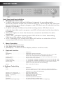
FRONT PANEL
Front Panel and key definition:
1. LED Indicator status area
• [1-8]LED Indicators: indicate 8 different channels for recording status,
(for the 4-channel model: only works for LED[1-4], others will be off). LEDs that
are on indicate recording in progress, and LEDs that are off indicate that the
system is in standby.
• [1-4]HD: indicate 4 different hard disk working status. LEDs that are on
indicate hard disk work in progress, and LED off indicate that the hard disk is
in standby.
• LINK/ACT: Lights on when the internet is connected and blinks for data
transferring.
• 100M/ 10M : indicates internet speed: LED will be on when transmitting
100M bps, LEDs will be off for 10M bps.
• VGA : indicates VGA connection status: LED will be on when the VGA is
connected, LED off when disconnected.
2.
•
•
•
3.
Menu Operation
Up, Down directional keys.
Left, Right directional keys.
[ENTER]Key: Confirm OR Time display while in monitor mode.
Playback function
Key . . . . . . . . . . . . . . . . . . . . . . . . . . . . .Definition
[Playback] . . . . . . . . . . . . . . . . . . . . . .Playback function activate
[Slow] . . . . . . . . . . . . . . . . . . . . . . . . . . .Playback with slow motion with speed at 1/2x, 1/4x, 1/8x,
resume at normal speed with [Playback]pressed
[Pause /Play] . . . . . . . . . . . . . . . . . . . . .Pause video while press once, frame-to-frame at re-press.
[Playback] . . . . . . . . . . . . . . . . . . . . . . .Key for resume to normal
[Fast Forward] . . . . . . . . . . . . . . . . . . . . 2x, 4x Speed available, Playback Key for resume at reg. play
[Fast Backward] . . . . . . . . . . . . . . . . . . 2x, 4x Speed available, Playback Key for resume at reg. play
[Recording] . . . . . . . . . . . . . . . . . . . . . .Available for 4 channels recording, single online monitor
system can play with manual recording.
[Stop] . . . . . . . . . . . . . . . . . . . . . . . . . . .Stop manual recording
4. Platform Control Key
Key . . . . . . . . . . . . . . . . . . . . . . . . . . . . .Definition
[0-9] . . . . . . . . . . . . . . . . . . . . . . . . . . . .Numeric buttons, for number key-in or video swapping.
For non-menu screen, 1, 2, 3 and 4 represent for the video
channel 1, 2, 3 and 4 respectively
[Zoom In +], [Zoom Out -] . . . . . . . . . .Zooming adjustment
[Brightness +], [Brightness -] . . . . . . . . .Brightness adjustment
[Focus +], [Focus -] . . . . . . . . . . . . . . . .Image Sharpness adjustment
[Auto] . . . . . . . . . . . . . . . . . . . . . . . . . . .Auto Mode activate
[Manual] . . . . . . . . . . . . . . . . . . . . . . . .Manual Adjustment Platform
[Default] . . . . . . . . . . . . . . . . . . . . . . . .Use with Default configuration
[Window Wiper/Lighting] . . . . . . . . . . .Control with window rain wiper and lighting
FRONT PANEL
5.
...continued
Other options
Key . . . . . . . . . . . . . . . . . . . . . . . . . . . . .Definition
[Power ON /Power Off] . . . . . . . . . . . .System turn on and off(Stand-by and start)
[Login/Locked]Key . . . . . . . . . . . . . . . .Login to enter to operate mode with require password and
lock current setting activation
[Status] . . . . . . . . . . . . . . . . . . . . . . . . . .Checking with record information store inside of hard drive.
[Display Swap] . . . . . . . . . . . . . . . . . . .Swapping between multi-channel and single channel
monitor system
[Channel Config] . . . . . . . . . . . . . . . . .Channel configuration
[Adjustment] . . . . . . . . . . . . . . . . . . . . .Display with the setting of brightness, colour, contrast,
motion detect sensitivity, adjust with[+], [-]
[Return] . . . . . . . . . . . . . . . . . . . . . . . . .Return back to operating screen from setup menu
[CF Card] . . . . . . . . . . . . . . . . . . . . . . .While CF card inserted, this button can activate for the
CF function, for more details please refer with your CF Card
operation instruction manual
[Language] . . . . . . . . . . . . . . . . . . . . . .English, Simplified Chinese, Tradition Chinese selectable
[Network] . . . . . . . . . . . . . . . . . . . . . . . .Network parameter setting
[Record] . . . . . . . . . . . . . . . . . . . . . . . .For 4 channels monitor system. Can activate 4 manual
records or for single channels the monitor system can activate
1 manual record
[Stop] . . . . . . . . . . . . . . . . . . . . . . . . . . .Stop manual recording
[Setting] . . . . . . . . . . . . . . . . . . . . . . . . .Setting with system configuration and parameters
[F1] . . . . . . . . . . . . . . . . . . . . . . . . . . . . .Time select while in Playback mode
[F2] . . . . . . . . . . . . . . . . . . . . . . . . . . . . .For single channel system, control menu activation while
this key being pressed. While left/right, up/down key pressed,
adjusted with station recorder left/right, up/down direction
movement,press[ENTER]return to original position.
[Zoom In +], [Zoom Out -] . . . . . . . . . .Zooming adjustment
[Brightness +], [Brightness -] . . . . . . . . .Brightness adjustment
[Focus +], [Focus -] . . . . . . . . . . . . . . . .Image Sharpness adjustment
[Auto] . . . . . . . . . . . . . . . . . . . . . . . . . . .Auto Mode activate
[Manual] . . . . . . . . . . . . . . . . . . . . . . . .Manual Adjustment Platform
[Default] . . . . . . . . . . . . . . . . . . . . . . . .Use with Default configuration
[Window Wiper/Lighting] . . . . . . . . . . .Control with window rain wiper and lighting
Control menu quit with re-press[F2]
[F3] . . . . . . . . . . . . . . . . . . . . . . . . . . . . .No specific function set for this key
[can be reserve for other function]
[F4] . . . . . . . . . . . . . . . . . . . . . . . . . . . . .While in monitor system, swap with BNC / VGA output
6.
Connection
CF Card: Compact Flash Card slot for upgrade and backup function;
IR: Infra red receiver
BACK PANEL
...continued
Back Panel and connection outlet:
1
2
3
4
5
6
7
8
9
10
11
Ventilation fan
AC220V power in
Power switch
Alert signal in/out/ RS-485: 4 channels input/ output
Audio input: provide 4 channels audio input
Audio output: 2 channels for audio out, left side for replay output, right side for
the surveillance output
Video output: 2 channels for video signal output, channel 1 for surveillance output,
channel 2 for mixed video output
Video input: Channel 1~4 for video signal input
VGA: output with external computer monitor, only for Playback screen or on time recording screen,
not for surveillance review
Method: Press[F2]in remote control after key in password,
then switch the screen from display output with monitor screen
RS-232: Standard RS-232 connection
Ventilation fan for main unit
MPEG4 Alarm connector pin definition:
Pin definition:
PIN
1
2
3
4
5
6
7
8
9
10
11
12
13
14
15
DEF
FUNCTION
IN0 . . . . . . . .Channel 1
IN1 . . . . . . . .Channel 2
IN2 . . . . . . . .Channel 3
IN3 . . . . . . . .Channel 4
IN4 . . . . . . . .NC
IN5 . . . . . . . .NC
IN6 . . . . . . . .NC
IN7 . . . . . . . .NC
OUT0 . . . . . .Channel 3
OUT1 . . . . . .Channel 4
OUT2
OUT3
3COM . . . . .Channel 1
3NO
3NC
Alarm
Alarm
Alarm
Alarm
input
input
input
input
Alarm output
Alarm output
Alarm output
PIN
DEF
FUNCTION
16 . . . .4COM . . . . . .Channel 2 Alarm output
17 . . . .4NO
18 . . . .4NC
19 . . . .COM
20 . . . .NO
21 . . . .NC . . . . . . . . .Power fault report output
22 . . . .COM
23 . . . .NO
24 . . . .NC . . . . . . . . .Fault report output
25 . . . .485A . . . . . . .485A
26 . . . .485B . . . . . . . .485B
27-38 . .GND . . . . . . . .Ground
39-44 . .+12V . . . . . . .+12V
2, 4 channels alert layout definition
1-2 channels for open socket switch output, no need for additional alarm driver.
3-4 channels for power levels output(OUT for low power out), require additional alarm drive add in here.
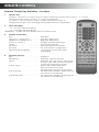
REMOTE CONTROL
Remote Control Key Definition / Function:
1.
Numeric Key
[0-9]Keys : Numeric, for number key-in or video swapping. For non-menu screen, 1, 2, 3 and 4
represent for the video channel 1, 2, 3 and 4 respectively.
[+], [-]Keys : Use for volume control, or while checking can play as
next/pervious page, even changing some parameters for configuration.
2.
Menu Operation
: Up, Down directional keys;
: Left, Right directional keys;
[ENTER]Key: Confirm OR Time display while in monitor mode;
3.
Platform Control Key
Key . . . . . . . . . . . . . . . . . . . . . . . . . . . . .Definition
[Zoom In +], [Zoom Out -] . . . . . . . . . .Zooming adjustment
[Brightness +], [Brightness -] . . . . . . . . .Brightness adjustment
[Focus +], [Focus -] . . . . . . . . . . . . . . . .Image Sharpness adjustment
[Auto] . . . . . . . . . . . . . . . . . . . . . . . . . . .Auto Mode activate
[Manual] . . . . . . . . . . . . . . . . . . . . . . . .Manual Adjustment Platform
[Default] . . . . . . . . . . . . . . . . . . . . . . . .Use with Default configuration
[Window Wiper/Lighting]
Control with window rain wiper
and lighting
4.
Playback function
Key . . . . . . . . . . . . . . . . . . . . . . . . . . . . .Definition
[Playback] . . . . . . . . . . . . . . . . . . . . . . .Playback function activate
[Slow] . . . . . . . . . . . . . . . . . . . . . . . . . . .Playback with slow motion with speed
at 1/2X, 1/4X, 1/8X, resume at normal
speed with [Playback] pressed
[Pause /Play] . . . . . . . . . . . . . . . . . . . . .Pause video while press once,
frame-to-frame at re-press.
[Playback] Key for resume to normal
[Fast Forward] . . . . . . . . . . . . . . . . . . . .X2, X4 Speed available, [Playback] Key
for resume at normal play.
[Fast Backward] . . . . . . . . . . . . . . . . . .X2, X4 Speed available, [Playback] Key
for resume at normal play.
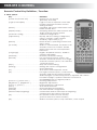
REMOTE CONTROL
Remote Control Key Definition / Function:
5. Other options
Key . . . . . . . . . . . . . . . . . . . . . . . . . . . . .Definition
[Power ON /Power Off] . . . . . . . . . . . .System turn on and off
(Stand-by and start)
[Login /Locked]Key . . . . . . . . . . . . . . .Login to enter to operate mode with
require password and lock current
setting activate
[Status] . . . . . . . . . . . . . . . . . . . . . . . . . .Checking with record information store
inside of hard drive
[Display Swap] . . . . . . . . . . . . . . . . . . .Swapping between multi-channel and
single channel monitor system
[Channel Config] . . . . . . . . . . . . . . . . .Channel configuration
[Adjustment] . . . . . . . . . . . . . . . . . . . . .Display with the setting of brightness,
colour, contrast, motion detect
sensitivity, adjust with [+], [-]
[Return] . . . . . . . . . . . . . . . . . . . . . . . . .Return back to operating screen from
setup menu
[CF Card] . . . . . . . . . . . . . . . . . . . . . . .While CF card inserted, this button can
activate for the CF function, details
please refer with CF Card operation
instruction
[Language] . . . . . . . . . . . . . . . . . . . . . .English, Simplified Chinese, Tradition
Chinese selectable
[Network] . . . . . . . . . . . . . . . . . . . . . . . .Network parameter setting
[Record] . . . . . . . . . . . . . . . . . . . . . . . .For 4 channels monitor system, can
activate 4 manual record, or for single
channels monitor system, can activate
1 manual record
[Stop] . . . . . . . . . . . . . . . . . . . . . . . . . . .Stop manual recording
[Setting] . . . . . . . . . . . . . . . . . . . . . . . . .Setting with system configuration
and parameters
[F1] . . . . . . . . . . . . . . . . . . . . . . . . . . . . .Time select while Playback mode
[F2] . . . . . . . . . . . . . . . . . . . . . . . . . . . . .For single channel system, control menu
activate while this key being pressed
While left/right, up/down key pressed, adjusted with station
recorder left/right, up/down direction movement,
press[ENTER]return to original position
[Zoom In +], [Zoom Out -] . . . . . . . . . .Zooming adjustment
[Brightness +], [Brightness -] . . . . . . . . .Brightness adjustment
[Focus +], [Focus -] . . . . . . . . . . . . . . . .Image Sharpness adjustment
[Auto] . . . . . . . . . . . . . . . . . . . . . . . . . . .Auto Mode activate
[Manual] . . . . . . . . . . . . . . . . . . . . . . . .Manual Adjustment Platform
[Default] . . . . . . . . . . . . . . . . . . . . . . . .Use with Default configuration
[Window Wiper/Lighting] . . . . . . . . . . .Control with window rain wiper and lighting
Control menu quit with re-press [F2]
[F3] . . . . . . . . . . . . . . . . . . . . . . . . . . . . .No specific function set for this key
[can be reserve for other function]
[F4] . . . . . . . . . . . . . . . . . . . . . . . . . . . . .While in monitor system, swap with BNC / VGA output
SYSTEM START-UP/SHUT DOWN
1. System Start up
Plug in your AC power, turn on the main unit, the red light will turn on while the system
boots up.
The system will be in standby mode. Press the [ON/OFF]button in front panel or remote
control, the red light will turn off, then the monitor will be activated to show as
4-channel windows status. There will be channel numbers shown to indicate each input
signal. Also, the top of screen will show the system time, number of hard disk and CF
card status (if applicable) shown in the center of the screen (there would be an alert
warning for no hard-disk installed), all of the information will be shown on the screen for
5~6 seconds. There will be a count down from 100 to 0 seconds (shown in red color
font). The system will be locked up after the count down reaches 0 seconds.
Notice: If the device is being set for timer record function, there is no need for standby
status after the system turns on, the system will go to multi-channel screen.
2. System Login
While the system is in lock-in status, press the [Login/Logoff] button in the front panel or
remote control, then the screen will have pop-up window appear stating
"Unit ID: *****, Unit ID : 000". Select the desired unit ID. "Password required: " then key in
your login password to enter into the system (The DVR will accept User password or
Administrator password).
1. After the user password is keyed in correctly, the message "USER PASSWORD
CORRECT" will be shown. Then the user can enter into restricted functional/feature
level functions with the device. (default password is : 00000000)
2. After the Administrator password is keyed in correctly a message "ADMIN
PASSWORD CORRECT" will appear, then the administrator can enter into all
functional/feature levels with the device. (default password is : 88888888)
Remark: There will be a difference between administrator and user level authorizations:
1. User can only playback all existing files, however, they can not stop the recording,
or access record setup. While the administrator can access all setup features.
2. After the password key in correctly, the count down timing (shown in top right
corner) will change from red to green color, this indicates that the user can access
different operations. There will be a 100 seconds operation time allowance after
each key-in button is pressed before system locked. The user will be required to reenter their password to returnto normal operation level once the "LOCK" indicator
shown in top right corner;
3. The user must key-in unit ID and password to enter into the operation system while in
LOCK status.
3. System Logoff
Press [Login/Logoff] button in the front panel or remote control after the record stop, the
system will go into standby mode.
Remark: Please make sure the system status is in standby mode before powering off. Please
do not power off the machine while it is in recording or playback system setting.
OPERATION INSTRUCTION
A. Menu Setup
While system is powered up, select [General Setting] to alter the system setup. The setup
menu can be seen below, highlight the item for selection and then press [Enter] to confirm.
(while system recording, not allow to change any setting for current channel)
GENERAL SETTINGS
Record Settings
Timer Record
Motion Detection
Alarm Record
Channels
Housings
Network
Language
Exit
A-1 General Parameter Setting:
Highlight and select "General Settings", then press [Enter] for this selection, the sub-menu will
shown (as below), then select the desired area.
GENERAL SETTINGS
Date / Time: 2003-05-08-23:59:00 Saturday
Unit ID:
Location:
HDD Overwrite: Yes
System: PAL NTSC
Admin_pwd_modify
Operate_pwd_modify
HDD Format
Restore Default Setting
Return
Date/ Time: Highlight and press [Enter] to confirm for change for date and time, range will
apply following:
•
•
•
•
•
•
YEAR: from 2000 to 2099, only change the last 2 digits (eg. "03" for Year 2003);
MONTH: Range 01 ~12;
DAY: Range 01~31;
HOUR: Range 00~23;
MINUTE: Range 00~59;
SECOND: Range 00~59;
After the [Return] key is pressed, the settings will be saved while power is on. However,
the settings will not be saved when the system restarts.
Unit ID: Changing the ID from 000 to 999, this ID used for the login identification.
Location: Key in the address for the location of the unit.
HDD Overwrite: Select one of two options: ON and OFF. When ON is selected, this will
allow recording continuously even if the hard disk space fulls up. The video will be
recording into FIFO (First-In-First-Out) format. When OFF is selected, the recording
function will stop once the HDD has filled up.
System: Select one of two options: "PAL" and "NTSC", then press [Enter] to confirm. NTSC is
the standard for North American video systems while PAL is standard for European
recording systems.
Admin_pwd_modify: Allows the you to change the administrator password, press[Enter] to
enter this function. It will require you to key-in the new password twice to confirm the
new password (this option only available with the administrator authorization level).
Operate_pwd_modify: Allows the you to change the operator password, press[Enter] to
enter this function. Require the user to key-in the new password twice to confirm.
HDD Format: This will allow you to format the hard disk drive while non-recording status,
while this option being selected, select with [START] and press [Enter] to confirm this
function.
Restore Default Setting: Restore all the settings to the factory level settings. A confirmation
option will appear to reconfirm system restore. A sample chart is shown on the next
page.
Return: Go back to previous menu.
OPERATION INSTRUCTION
Example: below is the record default setting:
Record Settings
Channel Quality Definition Frame Mode
1
14
CIF
25
CBR
2
02
CIF
25
CBR
3
03
CIF
25
CBR
4
04
CIF
25
CBR
HDD Store Mode
Centralize
Individual Compound
Return
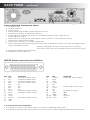
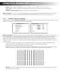
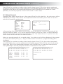
A-2 Record Parameter Setup:
While system operated, select "Record Setting" to changing some setting in here:
GENERAL SETTINGS
Record Settings
Timer Record
Motion Detection
Alarm Record
Channels
Housings
Network
Language
Exit
Record Settings
Channel Quality Definition Frame Mode
1
14
CIF
25
VBR
2
02
D1
12
CBR
3
03
HD1
6
VBR
4
04
D1
3
VBR
HDD Store Mode
Centralize
Individual Compound
Return
Channel (4 Channels): Move the cursor to enable channel recording function. If there is an
"X" to the left of a channel, recording is not allowed. Pressing [Enter] will enable the
channel.
HDD Format: This will allow you to format the hard disk drive while in non-recording status.
Select [START]and press[Enter] to confirm this function.
Image Quality: From 1 to 8 levels, 1 is the best quality. Use the cursor to select and press
[Enter] to confirm this function, with [+]and [-]to move the level.
Definition/Sharpness: From "D1, HD1, CIF" 3 difference levels. Using the cursor to select and
press [Enter] to confirm this function:
D1: DVD picture sharpness quality;
HD1: SVCD picture sharpness quality;
CIF: VCD picture sharpness quality;
Frame Rate: While in PAL video system choose from "25, 12, 06, 03, 01, 0.5" frame rate levels.
While in NTSC video system, choose from "30, 15, 08, 04, 02, 01" 6 difference frame rate
levels. Using the cursor to select and press [Enter] to confirm this function, and with
[+]and [-]to move the level.
PAL video system:
D1: Provided with totally 25 frame/ second in 4 channels;
HD1: Provided with totally 50 frame/ second in 4 channels;
CIF: Provided with totally 100 frame/ second in 4 channels;
NTSC video system:
D1: Provided with totally 30 frame/ second in 4 channels;
HD1: Provided with totally 60 frame/ second in 4 channels;
CIF: Provided with totally 120 frame/ second in 4 channels;
Mode: "VBR, CBR" are the 2 different encoding methods available in here. Using the cursor
to select and press [Enter] to confirm this function:
VBR: Variable Bit Rate encoding method;
CBR: Constant (non-variable) Bit Rate encoding method;
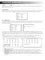
OPERATION INSTRUCTION
continued
Conversion Table for Image Quality and Encoding Rate
Image Quality (Encode Rate Kbit/Second)
Sharpness
Encode Method
CBR
1
2
3
4
5
6
7
8
D1
HD1
Fixed
Fixed
2400
1200
2200
1100
2000
1000
1800
900
1600
800
1200
600
1000
500
800
400
CIF
Fixed
MAX
900
2400
800
2200
700
2000
600
1800
500
1600
400
1200
300
1000
200
800
D1
VBR
MIN
2000
1800
1400
1200
1000
800
600
400
HD1
MAX
MIN
1200
900
1100
800
1000
700
900
600
800
500
600
400
500
300
400
200
CIF
MAX
MIN
900
600
800
600
700
500
600
400
500
300
400
200
300
200
200
100
HDD Store Mode: "Centralize, Individual, Compound" are 3 different hard disk storing modes
available in here. Using the cursor to select and press [Enter] to confirm this function:
• Centralize: All video signal and sound signals are stored into same one hard disk, and
then continuously with the next hard disk after the current one becomes full.
• Individual: Each channel of video signal and sound signals are stored into a different
hard disk, for example channel 1 recording into HDD1, and channel 2 recording into
HDD2.
• Compound: Channel 1 and 2 video and sound signal only record into HDD1 and
HDD2, taking into HDD1 first and then using HDD2 after the HDD1 is full. At the same
meaning that, Channel 3 and 4 video signal and sound signal only recording into
HDD3 and HDD4, taking into HDD3 first and then using HDD4 after HDD3 full.
Return: Using the cursor to select and press [Enter] to confirm back to main menu.
A-3
Timer Record Setting:
Highlight and select "Timer Record", then press [Enter]for this selection, the sub-menu will
shown (as below).
GENERAL SETTINGS
Record Settings
Timer Record
Motion Detection
Alarm Record
Channels
Housings
Network
Language
Exit
Timer Record Settings
Ch
1
2
3
4
Timer
On Off
On Off
On Off
On Off
Motion_Mode
On Off
On Off
On Off
On Off
Timer Record: "On, Off" are the 2 different status settings. Use the cursor to select and press
[Enter] to confirm this function. While timer selected, there will be 16 different setting tasks
for timer setup in each channel (8 different day types, and 2 different period settings available for each type):
Channel 1 Timer Record Settings
Date
Period 1
Period 2
Everyday
08:00-12:00 14:00-18:00
Mon
08:00-12:00 14:00-18:00
Tue
08:00-12:00 14:00-18:00
Wed
08:00-12:00 14:00-18:00
Thurs
08:00-12:00 14:00-18:00
Fri
08:00-12:00 14:00-18:00
Sat
08:00-12:00 14:00-18:00
Peak
08:00-12:00 14:00-18:00
Return
OPERATION INSTRUCTION
continued
• Date: Select either "Everyday", "Sun", "Mon", "Tue", "Wed", "Thu", "Fri", "Sat"
and "Peak", when "Peak" time selected, the device will not use the stand-by
function.
• Period 1 and Period 2: Select start time and end time.
Motion Mode: "On, Off" are the 2 different status settings to enable and disable this function respectively. Using the cursor to select and press [Enter] to confirm this function.
A-4
Motion Detection Setting:
Highlight and select Motion Detection, then press [Enter] for this selection, the sub-menu will
shown (as below), then select the required area.
GENERAL SETTINGS
Record Settings
Timer Record
Motion Detection
Alarm Record
Channels
Housings
Network
Language
Exit
Motion Detection
Channel
Effective
Region
1
2
3
4
Settings
Settings
Settings
Settings
Alarm
On
On
Off
Off
Return
Effective Region: Use the cursor to select Settings and press [Enter] to confirm this function.
Then there will be a region setting screen with full of square grid (as picture shown below),
press [Setting] to get the detect area as full screen (all the grid squares will turn a light
green square as selected) re-press [Setting] to cancel the selected areas (all grid squares
will turn back to clear, and there will be purple flashing cursor right in the centre of screen
for selection).
• Using the directional key to move purple cursor for selection. When the grid block
being selected (press [Enter] to select), the block will turn light green.
• Cancel with re-press [Enter] key in the block.
• When there are objects moving in the selected region, the block will turn yellow and
flashing. (This will activate the recording, if there had been pre-set already).
• Alarm: "On, Off" 2 different status settings. Using the cursor to select and press [Enter]
to confirm this function.
OPERATION INSTRUCTION
A-5
continued
Alarm Record Setting:
Highlight and select Alarm Record, then press [Enter] for this selection, the sub-menu will
shown (as below), then select the required area.
GENERAL SETTINGS
Record Settings
Timer Record
Motion Detection
Alarm Record
Channels
Housings
Network
Language
Exit
Alarm Record Settings
Ch Alarm In_Mode
1
On
Close
2
Off
Open
3
On
Open
4
Off
Open
Return
Alarm_Delay: 005s
Out_Delay: 005s
Keep_Delay: 005s
Multi_Ch_Rec: On
Multi_Ch_Output: On
Alarm: "On, Off" are the 2 different status settings available. Use the cursor to select
and press [Enter] to confirm this function. While "On" is selected, there will be 16
different task settings for timer setup in each channel (8 different day types, and
2 different period settings available for each type):
Channel 1 Alarm Record Settings
Date
Period 1
Period 2
Everyday
08:00-12:00 14:00-18:00
Mon
08:00-12:00 14:00-18:00
Tue
08:00-12:00 14:00-18:00
Wed
08:00-12:00 14:00-18:00
Thurs
08:00-12:00 14:00-18:00
Fri
08:00-12:00 14:00-18:00
Sat
08:00-12:00 14:00-18:00
Peak
08:00-12:00 14:00-18:00
Return
• Date: Select either "Everyday", "Sun", "Mon", "Tue", "Wed", "Thu", "Fri", "Sat" and "Peak".
When "Peak" time is selected, the device does not have the stand-by function.
• Period 1 and Period 2: Available to select the start time and end time.
In_Mode: "Open, Close" are the 2 different input modes for alarm signal input. When the
alarm system is set to the "Close" option, when open signal starts, the alarm signal is
produced. The input mode in here should be set as "Open".
Alarm_Delay: Key in the number key to setup the time delay (range from 0 to 300 seconds)
for alarm recording (default setting as 10 seconds).
Out_Delay: Key in the number key to setup the time delay (range from 0 to 300 seconds)
for alarm output (default setting as 10 seconds).
Keep_Delay: Key in the number key to setup time delay (range from 0 to 300 seconds) for
alarm warning signal (default setting as 10 seconds).
For example: If an alarm is produced at 23:30:50 the device should start the recording
from time 23:30:40 since the system per-recording time was set as 10 seconds. The
system will release the alarm warning signal. Whole recording depends on the alarm
time, per-recording alarm time and alarm warning signal to perform recording
Multi_Ch_Rec: "On, Off" are the 2 different status settings available. Use the cursor to select
and press [Enter] to confirm this function. While "On" is selected, there will be 4 multiple
channels interface display as shown below:
OPERATION INSTRUCTION
continued
Multi_Ch_Rec: "On, Off" are the 2 different status settings available. Use the cursor to select
and press [Enter] to confirm this function. While "On" is selected, there will be 4 multiple
channels interface display as shown below:
Alarm Record Settings
Ch Alarm In_Mode
1
On
Close
2
Off
Open
3
On
Open
4
Off
Open
Return
Multiple Channel Alarm Recording setting
Alarm Channel
1
2
Alarm_Delay: 005s
Out_Delay: 005s
Keep_Delay: 005s
Multi_Ch_Rec: On
Multi_Ch_Output: On
1
*
2
3
3
4
5
6
7
8
*
*
*
4
*
*
5
6
7
8
Return
•
•
•
•
Horizontal Row: Channel "1~8" (for 4 channels device only 4 available)
Vertical Column: Alarm Channel "1~8" (for 4 channels device only 4 available)
"*" : Press [Enter] to select and cancel this;
Example: As seen from above, for the row 1, while alarm channel 1 received signal,
the channel 1 and 2 start recording, channel 3 and 4 not taking any action.
• Example: For the row 2, while alarm channel 2 received signal, only channel 2 start
recording, other channels not taking any action.
Multi_Ch_Output: "On, Off" 2 difference status setting. Using the cursor to select and press
[Enter] to confirm this function. While "On" selected, there will be 4 multiple channels interface display as shown above.
A-6
Channel Setting:
Highlight and select Channels, then press [Enter]for this selection, the sub-menu will shown
(as below), then select the required area.
GENERAL SETTINGS
Record Settings
Timer Record
Motion Detection
Alarm Record
Channels
Housings
Network
Language
Exit
Channel Settings
Channel
1
2
3
4
Title
Warehouse
Cash
Cash 2
Main Desk
Cover
Yes
No
No
No
Time Insert
Yes
No
No
No
Return
• Title: Channel name. Use the cursor to select and press [Enter] to key-in the name
and re-press [Enter] to confirm this function.
• Cover: "On, Off" 2 difference status setting. Using the cursor to select and press [Enter]
to confirm this function. While "On" selected, there will be cover display setting as
shown below:
OPERATION INSTRUCTION
continued
• Use the directional key to move small yellow block selection. When 4 points of yellow
block are produced there will be q region wet up for the coverage setting area.
Time insert: "On, Off" are the 2 different status settings. Use the cursor to select and press
[Enter] to confirm this function. While "On" selected, a system clock will be shown while
recording.
A-7
Housing Setting:
Highlight and select Housings, then press [Enter]for the selection, the sub-menu will shown
(as below), then select the required area.
GENERAL SETTINGS
Record Settings
Timer Record
Motion Detection
Alarm Record
Channels
Housings
Network
Language
Exit
Housing Settings
Channel
1
2
3
4
Protocol
pelco-d
pelco-p
enkel
ccr-20g
BaudRate
1200
2400
4800
9600
No.
01
10
25
63
Return
Protocol: Using the cursor to select and press [Enter]to confirm difference protocol
(pelco-d/p/02-15 etc.);
BaudRate: Using the cursor to select and press [Enter] select difference rate at
1200/2400/4800/9600;
No: Using the cursor to select and press [Enter] select difference housing number at
(01~63).
A-8
Network Setting:
Highlight and select Network, then press [Enter] for this selection, the sub-menu will be
shown (as below), then select the required area.
GENERAL SETTINGS
Record Settings
Timer Record
Motion Detection
Alarm Record
Channels
Housings
Network
Language
Exit
Network Settings
IP Address:
Subnet mask:
Default gateway:
Transport protocol:
029, 010, 001,100
255,255,255,000
029,010,001,254
TCP/IP
Return
• IP Address: Use the cursor to select and press [Enter]to enter the IP address.
• Subnet mask: Use the cursor to select and press [Enter]to enter the subnet mask at
current location.
• Default Gateway: Use the cursor to select and press [Enter] select default gateway
according to current IP address.
• Transport protocol: Use the cursor to select and press [Enter] select.
A-9
Language Setting:
Make sure that English is the default setting.
OPERATION INSTRUCTION
A-10
continued
Exit:
Highlight and select Exit, then press [Enter] to confirm for save the change of setting then
return back to main menu.
B. Info Menu
While system is in use, select [Info Menu] to check the menu content. The info menu can be
seen as shown below, highlight the item for selection and then press [Enter]to confirm.
Info Menu
All
Alarm
Alarm
Operate
Channel
HDD
Machine
Exit
Record
Record
Log
Log
Status
Status
Info
B-1 All Record:
Highlight and select All Record, then press [Enter]for this selection, the sub-menu will shown
(as below), then select the required channel and date, press "Start" to see the record at
specific requirement.
Info Menu
All
Alarm
Alarm
Operate
Channel
HDD
Machine
Exit
Input date and time of all record
Record
Record
Log
Log
Status
Status
Info
Channel:
Time:
Start
Return
01
2003/11/28, 23:30
After pressing enter, there will be a sub-menu shown (as below), and the calendar will display dates 1 to 31 as per selected month, move the cursor to select different dates in order
to check the record and press [Enter] to view. A yellow font represents recording existance
for this.
If no recording exists for certain date, "No exist record" will be displayed. Using page up
("UP") and down ('DO") ("+/-" key) for those more than 1 page recording list.
01
12
23
CASH 1
CASH 2
FRONT
CASH 1
•
•
•
•
•
Channel 1 2003/11/28 Recording Info
02
03
04
05
06
07
08
09
10
11
13
14
15
16
17
18
19
20
21
22
24
25
26
27
28
29
30
31
UP
DO
08:30-09:00
09:30-10:00
11:30-12:00
17:00-18:00
R
M
A
R
CIF
CIF
CIF
CIF
25
25
25
25
01
12
23
Channel 1 2003/11/2 9 Recording Info
02
03
04
05
06
07
08
09
10
11
13
14
15
16
17
18
19
20
21
22
24
25
26
27
28
29
30
31
UP
DO
NO EXIST RECORD
Title: Channel name.
Recording Time: Period for the recording time, the length for each at 60 minutes.
Recording method: "R" for timer record, "M" for manual record, "A" for alarm record.
Sharpness: D1, HD1 and CIF to indicate the level of the recording information.
Frame Rate: While in PAL video system, "25, 12, 06, 03, 01, 0.5" frame rate levels will
available. While in NTSC video system, "30, 15, 08, 04, 02, 01" frame rate levels will be
available.
OPERATION INSTRUCTION
continued
Press [Enter] to see the recording video/audio signal, press [F1]for time select playback,
and press [SLOW] for slow motion playback at a different speed. Press [FF]for fast forward
playback and [FB]for fast backward playback, press [PAUSE] key to pause the video.
[RETURN] to exit the playback window and back to main menu.
B-2 Alarm Record:
Highlight and select Alarm Record, then press [Enter] for this selection, the sub-menu will be
displayed (as below. Then select the required channel and date, press "Start" to see the
record at a specific requirement.
Info Menu
All
Alarm
Alarm
Operate
Channel
HDD
Machine
Exit
Input date and time of alarm record
Record
Record
Log
Log
Status
Status
Info
Channel:
Time:
Start
Return
01
2003/11/28, 23:30
After pressing Start there will be a sub-menu shown (as below), and the calendar will display as well from date 1 to 31 at the selected month. Move the cursor to select different
dates to check the record and press [Enter] to see. The dates shown in a yellow font are
dates where there has been an alarm record.
When no recording exists for a certain date, "No exist record" will be displayed. Using page
up ("UP") and down ('DO") ("+/-" key) for dates when more than 1 page recording list is
available.
Press [Enter] to see the recording video/audio signal. Press [F1] for time select playback,
press [SLOW] for slow motion playback at different speeds. Press [FF] for fast forward playback and [FB] for fast backward playback, with [PAUSE] key to make the frame pause.
Press [RETURN] to exit the playback window and back to main menu.
Channel 1
01 02 03
12 13 14
23 24 25
CASH 1
CASH 2
FRONT
CASH 1
WAREH
RETURN
2003/11/28 Recording Info
04 05 06 07 08 09 10 11
15 16 17 18 19 20 21 22
26 27 28 29 30 31 UP DO
08:30-09:00
09:30-10:00
11:30-12:00
17:00-18:00
20:10-21:10
R
M
A
R
R
CIF
CIF
CIF
CIF
CIF
25
25
25
25
25
Channel 1
01 02 03
12 13 14
23 24 25
2003/11/28 Recording Info
04 05 06 07 08 09 10 11
15 16 17 18 19 20 21 22
26 27 28 29 30 31 UP DO
NO EXIST RECORD
RETURN
OPERATION INSTRUCTION
continued
B-3 Alarm Log:
Highlight and select Alarm Log, then press [Enter] for this selection, the sub-menu will be
shown (as below), this allows you to see the recent alarm status and report.
Info Menu
All
Alarm
Alarm
Operate
Channel
HDD
Machine
Alarm Log
Record
Record
Log
Log
Status
Status
Info
2003/11/28, 23:30 Alarm at :1
Return Page Up
Page Down First Page
Exit
B-4 Operate Log:
Highlight and select Operate Log, then press [Enter] for this selection, the sub-menu will be
shown (as below), this allow to show the recent operate status and report.
Info Menu
All
Alarm
Alarm
Operate
Channel
HDD
Machine
Operate Log
Record
Record
Log
Log
Status
Status
Info
2003/11/28, 23:30 Parameter Change
Return Page Up
Page Down First Page
Exit
B-5 Channel Status:
Highlight and select Channel Status, then press [Enter] for this selection, the sub-menu will
be shown (as below), this allows to show the 4 channel’s status, including image quality,
sharpness, frame rate.
Info Menu
All
Alarm
Alarm
Operate
Channel
HDD
Machine
Channel Status
Record
Record
Log
Log
Status
Status
Info
Exit
Ch
1
2
3
4
Status
Record
Idle
Record
Record
Q
2
2
2
2
Size
D1
D1
D1
D1
Frames
25
25
25
25
Alarm
Alarm
Alarm
Alarm
Alarm
Motion
Detection
Close
Close
Close
Close
Return
B-6 HDD Status:
Highlight and select HDD Status, then press [Enter] for this selection, the sub-menu will be
shown (as below), this allow you to view the hard disk status for 4 channels, including total
hard disk space and available space.
Info Menu
All
Alarm
Alarm
Operate
Channel
HDD
Machine
Exit
HDD Status
Record
Record
Log
Log
Status
Status
Info
HDD
1
2
3
4
Return
Status
Work
None
Work
Record
Capacity
040GB
000GB
000GB
000GB
Free_Space
012,000MB
000,000MB
000,000MB
000,000MB
OPERATION INSTRUCTION
continued
B-7 Machine Info:
Highlight and select Machine Info, then press [Enter] for this selection, the sub-menu will be
shown (as below), this allow to show all the machine ID number and software version.
Info Menu
All
Alarm
Alarm
Operate
Channel
HDD
Machine
Machine Info
Record
Record
Log
Log
Status
Status
Info
Unit ID.: 43743746194619463289573296
Version:
Return
Exit
B-8 Exit:
Highlight and select Exit, then press [Enter] to confirm for save the change of setting then
return back to main menu.
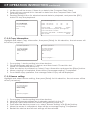
COMPACT FLASH CARD UPGRADE
AND OPERATION INSTRUCTION
C-1 Compact Flash Card Upgrade:
1. Using a PC to make sure your Compact Flash card formated into FAT32 format.
(if not already in the FAT32 format).
2. Insert the Compact Flash card into the DVR CF Slot while the DVR is turned off.
3. Press [ON/OFF] button without release to switch on the power;
4. Within 2~3 seconds the LED light (SYS and POWER) should be flashing and that means
that the upgrading is in progress.
5. Upgrading will take approx. 1 minute and both LEDs will turn off once upgrading has
completed.
6. Turn off the device and then remove the Compact Flash card from the slot.
7. Restart the device and the new software should be installed.
C-2 Compact Flash Card Backup:
In order to copy the data from hard disk into the Compact Flash card, please follow the
following procedures:
1. Insert the Compact Flash card into CF Slot before the DVR’s power is on.
2. Power on the device and stop all recording activity.
3. Press the [CF card] button in remote control or front panel, this will allow the copying
of all required information and data into Compact Flash card.
4. Re-Press the [CF card] button on the remote control or front panel to stop copying.
C-3 Playback Compact Flash Card Content:
In order to playback the data from the Compact Flash card, press [CF card] to enter the
Compact Flash card menu and use the cursor to select operation:
C-3-1 Compact Flash card management:
Highlight and select CF Manage, then press [Enter] for this selection, the sub-menu will be
shown (as seen below), this allows you to view all the information of the current CF card.
CF Card Operation
CF Card Management
CF Card Manage
Copy Information
Renew setting
No Record
Exit
Previous Page
Next Page
Delete
Help: Press Enter to playback, press right key button
then Enter to delete
Disk Space: 000,060MB
Return
Availability: 000,057MB
CF OPERATION INSTRUCTION
continued
1. No Record will be shown if there is no data in the Compact Flash Card.
2. There will be a record list to viewed for data from the Compact Flash Card
(as shown below).
3. Pressing [Enter] button for selected record data to playback, and press the [ESC]
button to stop the playback.
CF Card Operation
CF Card Management
CF Card Manage
Copy Information
Renew setting
XXXX
XXXX
Exit
09:15-09-16
10:10-10:12
M
M
CIF
CIF
25
25
Previous Page
Next Page
Delete
Help: Press Enter to playback, press right key
button then Enter to delete
Disk Space: 000,060MB
SIZE: 7,813KB
Availability: 000,057MB
Return
C-3-2 Copy Information:
Highlight and select Copy Information, then press [Enter] for this selection, the sub-menu will
be shown (as below):
CF Card Operation
CF Card Operation
CF Card Manage
Copy Information
Renew setting
CF Card Manage
Copy Information
Renew setting
Exit
Exit
Copy in progress……..
1. For copying 1 device setting into other devices.
2. Get all necessary settings in 1 device, and then insert CF card into slot
(insert CF card before power on).
3. After the device is powered on, select Copy Information and press the [Enter] button.
4. When copying is completed, there will be a message reading "Completed".
5. For a failed copy operation, the message Failed Copy will be displayed.
C-3-3 Renew setting:
Highlight and select Renew setting, then press [Enter] for this selection, the sub-menu will be
shown (as below):
CF Card Operation
CF Card Manage
Copy Information
Renew setting
Exit
Renew in progress...
1.
2.
3.
4.
5.
6.
For copying 1 device setting into other devices.
When all necessary settings are in already copied into the CF.
Using this card and insert into device slot (before power on).
Then after the device power is on, select "Renew Setting" with [Enter] button.
When the renew is completed, there will be a message saying "Completed".
Restart the device and all new settings will be restored.
RECORDING AND PLAYBACK
INSTRUCTION
D-1
Recording
Manual Recording:
1. Use the [Record] button to start recording, will be a red dot on the top right side
corner of the monitor which indicates the recording is in progress.
2. Press the [Stop] button to stop the recording and the red dot will turn off.
Timer Recording:
Refer to section A-3
Remark: The Channel 1 timer setting has the "Peak" time setting (from number 16 option),
the peak setting is not available for other channel. After the "Peak" had been selected,
the device will not have any stand-by mode while no setting required.
Alarm Recording:
Refer to section A-4
Remark: When the device is in stand-by mode, there would be a 15~20 second time
delay when the alarm recording activates and recording starts.
D-2
Playback
Playback all record:
Refer to section C-1
Playback Alarm record:
Refer to section C-2
Playback the recent record:
Press the [Play] button to playback current channel information;
D-3
Playback with time select
1. Use the [F1] button for current playback channel, to select the time for playback
2. Use the [Stop] button to stop the playback.
D-4
Stop Playback
1. Use the [Stop] button to stop the playback;
D-5
Slow Playback:
1. Use the [Slow] button to slow motion the playback, with speeds at 1/2, 1/4 or 1/8.
2. Use the [Play] button to return to normal speed.
D-6
Pause Playback and Frame by Frame playback
1. Use the [Pause] button to pause the motion.
2. While motion is paused, using [Pause] again to play frame by frame playback.
3. Press the [Play] button to return to normal speed.
D-7
Fast Forward
1. Press the [FF] button to perform fast forward playback, with speeds at X2 or X4.
2. Press the [Play] button to return to normal speed.
D-8
Fast Backward
1. Press the [FB] button to perform fast backward playback, with speed at X2 or X4.
2. Press the [Play] button to return to normal speed.
ADJUSTMENT FOR PICTURE
PARAMETER AND SOUND LEVEL
E-1
Parameter adjustment
1. Use the [Adjust] button to adjust brightness, color, contrast and the motion detect
sensitivity level.
2. Use the [+] or [-] button for adjustment up and down.
3. Returns to menu after 5 seconds idle time without any adjustment.
TECHNICAL SPECIFICATION DATA
E-1
Parameter adjustment
1. Use the [Adjust] button to adjust brightness, color, contrast and the motion detect
sensitivity level.
2. Use the [+] or [-] button for adjus
Item
System
Device Param eter
UI Language
User Interface
Security
Video Input
Video Output
Video
Video Display
Video Standard
System Resource
Audio
Audio Input
Audio Output
Basic output
S/N
Recording Format
Compression
Encoding
Image Format
Video Standard
Audio Standard
Digital
Processing
and Storing
Alarm
Com port
Video Freq.
Audio Freq.
Audio Size Rate
Video Size Rate
Storage
Image Quality
Max Frame Rate
Resolution
Data capture
Motion Detect
Input
Output
Alarm mode
Serial Port
Serial Port
Netw ork port
Specification / Details
English/ Simplified Chinese/ Traditional Chinese
Icon operation interface (OSD menu)
User level passw ord, administer level passw ord
4 independent input w ith 1.0Vp-p, 75Ù BNC
1 PAL/NTSC output w ith 1.0Vp-p, 75Ù BNC, composite video
1 VGA output
1 channel and 4 channels w ith difference display mode
PAL: 25 frames per second CCIR625 lines 50 Hz
NTSC: 30 frames per second CCIR525 lines 60 Hz
Real time recording w ith 1 channel playback and 4 channels monitoring
Online real time monitor
4 channels independent input, L, R Channels 600Ù RCA
1 channel from monitor mode, 1 channel from playback mode 600Ù RCA
1.0—2.2V
?-30dB
Video and sound at same time
PCM
MPEG-4 Variable encode rate \ Fixed encode rate
CIF( 352×288 pixels)
1/2D1( 704×288 pixels)
D1( 704×576 pixels)
ISO14496
PCM
12.5K-112.5Kbyte/s
8Kbyte/s
28.8Mbyte/hour
45M-405Mbyte/hour
4 IDE hard disk, support 200G or
8 Adjustable levels
25 frames/ sec/ channel
Playback 352×288 pixels,
Real time 704×576 pixels,
VGA output 720×576 pixels
Bi-directional
25K-150Kbyte/s
50K-300Kbyte/s
90M-540Mbyte/hour
larger hard disk size
180M-1080Mbyte/hour
12.5 frames/ sec/ channel
Playback 704×288 pixels,
Real time 704×576 pixels,
VGA output 720×576 pixels
6.25 frames/ sec/ channel
Playback 704×576 pixels,
Real time704×576 pixels,
VGA output 720×576 pixels
Independent setting with each channel, with 192 detect regio n fo r each channel and adjustable mo tio n sensitivity
4 independent input channels
4 independent alarm output ( 2 voltage output, 2 open sw itch w ith output at 12VDC, 500MA)
Open / Short
RS485, extendable w ith external modem
RS232, common serial port
RJ-45 10M/100M boardband port
Internet Protocol
Support TCP/IP, UDP/IP
Transfer mode
Brow er
IE brow er
Dial-up, ADSL, ISDN, internet, intranet
TECHNICAL SPECIFICATION DATA
Pow er
Consumption
Working Temperature
Others
AC 220V±20%, 50Hz±2%
15W( excluding w ith hard disk)
0~50
Working Humidity
=80%
Outer Dimension
2U Standard device box 440( W) ×90( H) ×420( D) mm
Weight
Clock
5.5KG( Excluding hard disk)
Build-in system clock and calendar
APPENDIX
I-1
IDE requirement:
1.
2.
3.
4.
5.
There are 2 IDE ports in the main board: 1 is master and 1 is slave.
J4 IDE (the one close with power port) as master IDE port.
J10 IDE as slave IDE port.
Master hard disk must connect first before slave hard disk operate.
Also while 2 hard disks connect with IDE, they must be set with different jumpers
to make this functional.
I-2 Playback DVR Hard disk with PC:
The DVR file information requires the conversion program (STMTOAVI.EXE which comes
with the product) to make it as PC compatible and readable. It simply convert those
*.stm file into *.avi file, which can play with media player from PC.
Here are some steps for STMTOAVI software instruction:
1. Click the STMTOAVI program to start.
2. Open file with select those *.stm file.
3. Start the conversion.
4. Provided with the output file name and output path.
5. After conversion, there will be a new file with *.avi and must used with DIVX
playback software to run the avi file (DIVX version prefer with 5.03 or better).
NOTES