1
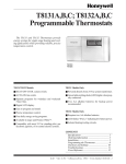
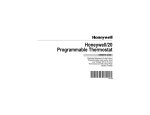
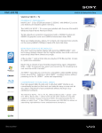
VIDEO
User Manual for Digital Video Recording Computer
Version 1.0
2 July 2007
Theodore G. Cleveland
July 2, 2007
1
Contents
1 Introduction
3
2 Hardware Configuration
3
3 Operating the Video System
3.1 Camera Connections . . . . . . . . .
3.2 Starting the Video Software . . . . .
3.3 Changing Settings – Start Recording
3.4 Viewing captured images – Playback
.
.
.
.
.
.
.
.
.
.
.
.
.
.
.
.
.
.
.
.
.
.
.
.
.
.
.
.
.
.
.
.
.
.
.
.
.
.
.
.
.
.
.
.
.
.
.
.
.
.
.
.
.
.
.
.
.
.
.
.
.
.
.
.
.
.
.
.
.
.
.
.
.
.
.
.
.
.
.
.
.
.
.
.
.
.
.
.
4
4
5
7
10
4 Saving the Image Files
14
5 Editing files for External Media Viewers
14
6 Bibliography
15
List of Figures
1
2
3
4
5
6
7
8
9
10
11
12
13
14
15
16
DVR cards in PCI slots 1-3; Slot 0 is the video monitor. Camera 2 connected
Swann C500 CCD Camera during system maintenance . . . . . . . . . . . .
Desktop after successful login . . . . . . . . . . . . . . . . . . . . . . . . . .
Loading the DVR program – takes some time . . . . . . . . . . . . . . . . .
DVR program loaded and running . . . . . . . . . . . . . . . . . . . . . . .
Selecting the login icon (a padlock) . . . . . . . . . . . . . . . . . . . . . . .
Logging into the DVR system – enter nothing, just choose “OK” . . . . . .
Basic Settings Dialog Box . . . . . . . . . . . . . . . . . . . . . . . . . . . .
Basic Settings – Camera Start . . . . . . . . . . . . . . . . . . . . . . . . . .
Cameras 1-3 recording; only Camera 2 has signal . . . . . . . . . . . . . . .
Playback control window . . . . . . . . . . . . . . . . . . . . . . . . . . . . .
Selecting cameras . . . . . . . . . . . . . . . . . . . . . . . . . . . . . . . . .
Selecting time window to start playback . . . . . . . . . . . . . . . . . . . .
Playback in progress . . . . . . . . . . . . . . . . . . . . . . . . . . . . . . .
Playback halted; ready for frame-by-frame . . . . . . . . . . . . . . . . . . .
Small-flume experiment video, single frame capture . . . . . . . . . . . . . .
4
5
6
6
7
7
8
8
9
10
11
11
12
13
13
14
List of Tables
1
Hardware Configuration . . . . . . . . . . . . . . . . . . . . . . . . . . . . .
2
3
1
Introduction
The video computer was built in 2004 to capture and record images during flume studies.
The images are subsequently analyzed frame-by-frame to generate quantitative measurements using the video time stamp and known distances in the images. The frame-by-frame
analysis is performed by the video operator, and image processing software is not used.
The computer also reads level logger (pressure transducers with on-board datalogging capability) data through the USB port. This combination allows both image capture and
water level data collection in the laboratory using tools that are field portable and field
equivalent.
2
Hardware Configuration
The hardware for the system is comprised of an end-user built PC computer and ancillary
equipment (DVR cards and cameras) with the specifications listed in Table 1.
Table 1: Hardware Configuration
Component Name
Detailed Description
Motherboard
PC Chips M848A
Processor
AMD K7 Sempron 2800 (1.2 GHz)
RAM
512 MB DDR 400
Hard Drive
200GB Seagate Ultra ATA/100 7200
CDROM
NEC CDR 1800A
FD
1.2 MB IDE (Generic)
DVR Input 1
Swann PC DVR-4 TD-3004F6.4
DVR Input 2
Swann PC DVR-4 TD-3004F6.4
DVR Input 3
Swann PC DVR-4 TD-3004F6.4
Video Input
Video Input
Video Input
Swann C500 CCD Color Camera
Swann C500 CCD Color Camera
Swann C500 CCD Color Camera
Power supply
Chassis
Allied AL400-ATX 400W
Antec 8U ATX Tower
Op System
DVR
Levelloggers
Microsoft Windows 2000 SP1
Swann PC-DVR-4-Net V4 (2005 0707)
Solnist Levellogger V3.0
3
3
Operating the Video System
This section explains how to operate the video collection system when it is properly working
– this is not a maintenance manual 1
3.1
Camera Connections
Figure 1 is an image of the back of the computer. The DVR cards are the three cards with
rows of 4 BNC connections. The camera numbering convention is from top to bottom (in
the figure) right to left. The card in PCI Slot 2 with the camera cable connection is Camera
2. The connector immediately above is Camera 1, and immediately below is Camera 3.
The column to the left (from top to bottom) is cameras 4-6, and so-on.
Figure 1: DVR cards in PCI slots 1-3; Slot 0 is the video monitor. Camera 2 connected
Multiple cards are needed because the cards poll cameras if they are connected to the same
card. The cards can aquire 30 frames per second total, thus multiple cameras on a single
card would reduce the image rate per camera at roughly 30
N frames-per-second where N is
the camera count per card.
Using three cards, one camera each the system can acquire 30 fps per camera. The desired
connection for three cameras are one camera per card, in the right-most BNC connector.
In the imaging software, these will be cameras 1-3.
Figure 2 is an image of one of the cameras (it is connected to the computer in figure 1 and
appears in the image background). The camera has three adjustments on the lens system.
1
The video system requires significant maintenance by a system administrator, but careful use should
allow the system to operate for months at a time without maintenance.
4
Figure 2: Swann C500 CCD Camera during system maintenance
An iris adjustment (middle ring), a crude focus, and a wide angle-telephoto adjustment.
The three adjustments are interdependent and obtaining a sharp focus is a tedious trialand-error process. The adjustments are best made using the 24-inch color monitor and
binoculars2 .
3.2
Starting the Video Software
This section assumes the user is logged on to the video computer. The computer is built for
single-user, stand-alone use. The username is uh; the password is irecord. The analyst
should heed to two following warnings: DO NOT CHANGE PASSWORDS and DO
NOT CONNECT THE COMPUTER TO A PUBLIC NETWORK.
Data are stored on the computer and will be moved from the computer to archive either
by an external USB device or via a private network.
To start the software, first log onto the computer as uh. The resulting desktop should look
something like Figure 3
Next select the PCDVR-4-Net program either from the desktop or from the programs
file and launch the program. The program takes awhile to load, during the loading the
desktop will have a splash image telling you to wait as in Figure 4. If the load is successful,
then the DVR system will be displayed – the display uses the entire monitor screen, but
2
Binoculars are needed because the physical distance from the camera to the monitor is on the order of
30 feet; the effort to climb up and down the ladder in the large flume would make such adjustments nearly
impossible in a reasonable amount of time
5
Figure 3: Desktop after successful login
Figure 4: Loading the DVR program – takes some time
has a minimization switch in the upper right hand corner. Figure 5 is a screen capture of
the DVR software with one camera active.
Along the right hand edge are some controls, along the bottom are some other controls. If
there is an active camera there will be an image showing (as in the example). If there is
an active channel, but no camera, there will be no image and the indicator “lights” on the
bottom edge will be blue – indicating that the program is trying to access the indicated
cameras, but there is no signal. If the light is grey (off), either the camera is not recording
or the camera is not active (a program setting).
6
Figure 5: DVR program loaded and running
3.3
Changing Settings – Start Recording
To change settings (a required procedure to start and stop recording) you need to log into
the software. The icon on the right edge that looks like a padlock is how the program is
accessed. Simply click on the icon as in Figure 6, to be able to access the software internal
settings.
Figure 6: Selecting the login icon (a padlock)
The software will prompt you with a username SYSTEM and request a password. The
password is “blank” - do not type anything into the dialog box, simply choose “OK” as in
Figure 7
7
Figure 7: Logging into the DVR system – enter nothing, just choose “OK”
To change settings you click on the icon that looks like a box-wrench (third icon from the
top of the icon column). When it enters the settings system you should get a window that
looks like Figure 8. This image warrants some important description.
Figure 8: Basic Settings Dialog Box
The significant settings are in the category of storage disk. On this system, the storage disk
should be :D. The other two drive partitions on the system are for the operating system
8
and the install system3 . The other parts of the settings can be left alone4 .
The lower portion of the settings deals with the actual camera operations. The research
will use cameras 1-3 exclusively. Generally you will be manually starting and stopping
cameras with this input window. To start a camera, click “Manual Record” associated
with the individual camera. Verify that the record rate is 30 frames-per-second. If you
accidently click the entire row as manual record the frame rate will be much less than 30
frames-per-second. Figure 9 is an example of starting cameras 1-3, inclusive. The return
icon starts the recording.
Figure 9: Basic Settings – Camera Start
When the system is recording, active channels with input are indicated by green lights at
the bottom of the DVR software window, as shown in Figure 10
To stop recording after an experiment, you reverse the process. Go to the settings page
and turn off the various cameras.
3
While user “uh” has access to these two partitions, try not to write to them, they contain the operating
system files and some ancillary disaster recovery files. The drive space in these two partitions is too small
to log very much video before filling up.
4
The values in this manual may be different from values eventually set with regards to resolution,
captioning, etc.
9
Figure 10: Cameras 1-3 recording; only Camera 2 has signal
3.4
Viewing captured images – Playback
Once an experiment is captured, the playback system is used to review the experiment and
perform the frame-by-frame analysis. The computer can playback and continue to record,
there may be some reason to do both simultaneously when tuning experiments, but for most
of the work you will probably record experiments, stop recording then playback.
The playback icon is the second icon from the top, just below the padlock icon, just above
the wrench icon used to login to the software settings system. When the playback is selected
a control window like Figure 11 is displayed. In this window you select cameras to playback,
the start time (using slider at bottom) and playback speed, either real-rate, slow-rate, fastrate, or frame-by-frame. In the research you will generally be viewing a fast-rate to locate
phenomenon, then frame-by-frame to make measurements and computations.
Camera selection is done by choosing a playback scheme - either a single camera, four,
nine, etc. from the grid display below and to the right of the darkened playback screen. In
this manual we select the 4-camera grid, then indicate which cameras to playback5 .
In Figure 12 the four camera grid is chosen and the software then presents which camera
files are eligible, in this example cameras 1-3 are selected for playback. Of note, there is
5
The data are stored on disk, the camera naming scheme really points to directories of image files stored
on disk with their time stamp and camera address (name).
10
Figure 11: Playback control window
only one camera running in the example so two cameras will not be displayed and only
camera 2 will have non-null playback.
Figure 12: Selecting cameras
11
Once the cameras are selected, below the playback screen the slider window indicates which
camera files will be examined6 , and the time stamp range available. Figure 13 displays
the result of camera selection and shows which camera files will be presented. Notice that
only camera 2 has any recorded data indicated by the blue bar extending rightward in
the time axis. The slider can be moved with the mouse to a convenient starting time and
playback started by selecting the right arrow on the playback controls (same row as the
grid select).
Figure 13: Selecting time window to start playback
Notice how the time stamp changes from 00:00:00 to a non-zero time. The time stamps
1
1
are in 10
of a second although each frame in the recording may be only 30
th of a second.
In general in frame-by-frame, one counts frames to obtain elapsed times. The time stamp
2
will always be within 30
th of the correct time. Also of note the time scale can be expanded
and contracted by clocking on the time axis near the slider.
Figure 14 shows a playback in progress (screen capture during playback), the time scale is
incrementing, the image is moving, and the pause button becomes active. As the playback
progresses the analyst can move the slider as needed to examine different parts of the files
to find the phenomenon of interest. This entire process is tedious and requires immense
patience – frequent breaks may be necessary; hence the recommendation not to analyze
during data collection. When an area of interest is located, the playback can be paused
and the analyst can switch to frame-by-frame analysis.
6
The selected cameras are indicated by check marks next to their address
12
Figure 14: Playback in progress
Figure 15 shows a playback window ready for frame-by-frame analysis. Notice the control
Figure 15: Playback halted; ready for frame-by-frame
buttons used for forward and reverse one frame are located to the right-most of the button
13
row. When running frame-by-frame, the author recomends that the analyst write the timestamp at the beginning of the analysis so if the playback button is accidently pressed, the
analyst can get back to the area of interest rapidly.
4
Saving the Image Files
Image files are automatically saved in a directory called DVR Data/VIDEO by camera
name. The file names are in the format YYYYMMDDHHMMSS.avi The files are standard
.avi files with time stamps imbedded. From time to time, the analyst will want to copy
the files to external media for archive. The program automatically overwrites files when
the disk is full so once interesting data are collected they should be copied to external
media.
5
Editing files for External Media Viewers
The video files are directly viewable in Windows Media Viewer. The analyst will have to adjust color and brightness to make short clips of interesting phenomenon. The video files are
also viewable on a Macintosh using QuickTime with the Flip4Mac package installed.
Figure 16: Small-flume experiment video, single frame capture
The free package allows editing, but superimposes a “trial-copy” banner on the movie.
14
Using QuickTime and the Grap utility, individual frames can be selected for viewing and
documentation. Figure 16 shows a single frame capture made using the Grap utility (in
Mac OSX) while running the QuickTime movie.
In practice, quantitative computations will likely be made using the DVR software, while
the special cases will be viewed and edited externally. The external viewers will be of value
when report writing, but otherwise are not terribly meaningful.
6
Using the Level-Loggers
Content to be added in next version.
7
Bibliography
1. PC Chips M848A User’s Guide
2. Swann PC DVR4-Net Security Guardian Monitoring Kit FAQ (www.swannsecurity.com)
3. Swann SuperDVR & TDF Cards User Manual (www.swansecurity.com)
4. http://www.microsoft.com/downloads/ (Location of Flip4Mac and WMV 9.0 for
Mac)
15