1
SUPERSERVER 6015B-3R User's Manual
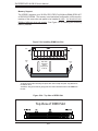
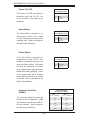
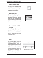
JLAN1/2 (Ethernet Ports)
Two Ethernet ports (designated JLAN1
and JLAN2) are located beside the
VGA port on the I/O backplane. These
ports accept RJ45 type cables.
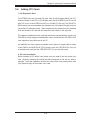
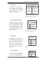
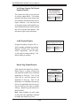
Alarm Reset (JAR)
The system will notify you in the event
Alarm Reset
Pin Definitions (JAR)
of a power supply failure. This feature
assumes that Super Micro redundant
power supply units are installed in the
chassis. Connect a microswitch to the
JAR header to disable the power supply
fail alarm.
Pin#
Definition
2
+5V
1
Ground
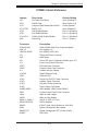
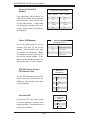
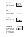
Compact Flash Card PWR
Connector
A Compact Flash Card Power Connector
is located at JWF1. For the Compact
Flash Card to work properly, you will
first need to connect a power cable to
JWF1 and correctly set the Compact
Flash Jumper (JCF1).
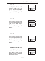
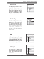
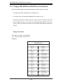
SGPIO
The two headers labeled SGPIO1 and
SGPIO2 are for SGPIO (Serial General
Purpose Input/Output). SGPIO provides a bus between the SAS controller
and the SAS drive backplane to provide
SAS enclosure management functions.
Connect the appropriate cables from
the backplane to the SGPIO1 and
SGPIO2 headers to utilize SAS management functions on your system.
5-18
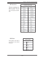
SGPIO Header
Pin Definitions (SGPIO1, SGPIO2)
Pin#
Definition
Pin #
Definition
1
NC
2
NC
3
Ground
4
Data
5
Load
6
Ground
7
NC
8
NC
Note: NC indicates no connection.