1
STIHL SR 32D, 4DD
Instruction Manual
Owner's Manual
'"
iii
Assembling
Safety Precautions
Operating Instructions
Maintenance
.
&RQWHQWV
Controls
Safety Precautions
Assembly of Unit
Fuel
Fueling
Control Handle
Starting
Air Filter
Adjusting the Carburetor
Operating Instructions
Checking Spark Plug
Replacing the Starter Rope
and Rewind Spring
Special Accessories
Metering Unit
Notes on Use of Mistblower
2
4
11
14
15
16
17
19
20
21
22
23
26
27
28
Maintenance Chart
37
Specifications
38
STIHL Incorporated Federal Emission
Control Warranty Statement
39
This Manual contains operating and
safety instructions for all STIHL SR 320,
SR 400 mistblowers.
Pay special attention to the safety
precautions outlined on pages 4 to 10.
Allow only persons who understand this
Manual to operate your mistblower.
To receive maximum performance and
satisfaction from your STIHL mistblower,
it is important that you read and understand the maintenance and safety
precautions before using your mistblower.
Contact your STIHL dealer or the STIHL
distributor for your area if you do not
understand any of the instructions in this
Manual.
:DUQLQJ
Printed on chlorine-free paper
Because a mistblower is a high-speed
tool, some special safety precautions
must be observed as with any other
power tool to reduce the risk of personal
injury. Careless or improper use may
cause serious or even fatal injury.
STIHL’s philosophy is to continually
improve all of its products. As a result,
engineering changes and improvements
are made from time-to-time. If the operating characteristics or the appearance of
your mistblower differ from those
described in this Manual, please contact
your STIHL dealer for information and
assistance.
1999 Andreas Stihl AG & Co., Waiblingen
0458 352 3021. M0,15. G9. PM. Printed in USA
65
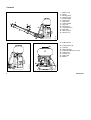
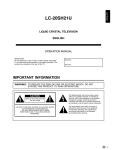
&RQWUROV
1 = Baffle screen
2 = Nozzle
3 = Metering knob
4 = Extension tube
5 = Throttle trigger
6 = Setting lever
7 = Stop switch
8 = Control handle
9 = Stop cock
10 = Pleated hose
11 = Carrying harness
12 = Back plate
13 = Back rest pad
14 = Air filter cover
3
6
7
8
9
5
2
4
11
14
12
10
BA001 KN
1
13
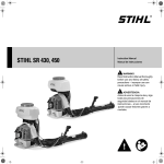
15 = Rubber buffers
16 = Container filler cap
17 = Container
18 = Spark plug boot
19 = Carburator adjustment screws
20 = Choke knob
21 = Fuel filler cap
22 = Starter grip
23 = Muffler
16
17
18
15
19
23
21
22
A003 KN
15
352BA002 KN
20
65
'HILQLWLRQV
%DIIOHVFUHHQ
To vary the direction and shape of
the spray.
1R]]OH
Directs and widens the spray.
0HWHULQJNQRE
For varying the spraying rate.
([WHQVLRQWXEH
Accessory for lengthening the
discharge tube.
&DUULQJKDUQHVV
For carrying the unit.
)XHOILOOHUFDS
For closing the fuel tank.
%DFNSODWH
Helps protect the back of the user.
6WDUWHUJULS
The grip of the pull starter, which is
the device to start the engine.
%DFNUHVWSDG
Increases carrying comfort.
$LUILOWHUFRYHU
Covers the air filter element.
7KURWWOHWULJJHU
Controls the speed of the engine.
5XEEHUEXIIHUV
Elements designed to reduce the
transmission of vibrations created by
the engine to the operators back.
6HWWLQJOHYHU
Sets the throttle to various positions.
&RQWDLQHUILOOHUFDS
For closing the container.
6WRSVZLWFK
Stops engine.
&RQWDLQHU
Contains the material to be sprayed.
&RQWUROKDQGOH
Handle on the flexible hose to hold
and direct the tube in the required
direction.
6SDUNSOXJERRW
Connects the spark plug to the
ignition wire.
6WRSFRFN
Opens and closes spray liquid hose.
3OHDWHGKRVH
For spraying, dusting or spreading
in the desired direction.
65
0XIIOHU
Attenuates exhaust noises and
diverts exhaust gases away from
operator.
&DUEXUDWRUDGMXVWLQJVFUHZV
For tuning carburator.
&KRNHNQRE
Eases engine starting by enriching
mixture.
6DIHW\3UHFDXWLRQV
:DUQLQJ
6DIHXVHRIDPLVWEORZHULQYROYHV
The use of any mistblower
may be dangerous. It is
important that you read, fully
understand and observe the
following safety precautions and
warnings.
Reread the owner‘s manual
and the safety instructions
periodically.
:DUQLQJ
Careless or improper use of the machine may cause serious injury. Have
your STIHL Dealer show you how to
operate your mistblower. Observe all
applicable local safety regulations,
standards and ordinances.
:DUQLQJ
Minors should never be allowed to use a
mistblower: Bystanders, especially children, and animals should not be allowed
in the area where a machine is in use.
Never let the unit run unattended.
Do not lend or rent your machine without
the owner‘s manual. Be sure that
anyone using your unit understands the
information contained in this manual.
Most of these safety precautions and
warnings apply to the use of all STIHL
mistblowers. Different models may have
different parts and controls. See the appropriate section of your owner‘s manual
for a description of the controls and
function of the parts of your machine.
1.
2.
3.
the operator
the mistblower
the use of the mistblower .
7+(23(5$725
3K\VLFDO&RQGLWLRQ
All factors which contribute to whitefinger
disease are not known, but cold weather,
smoking and diseases or physical
conditions that affect blood vessels and
blood transport, as well as high vibration
levels and long periods of exposure to
vibration are mentioned as factors in the
development of whitefinger disease. In
order to reduce the risk of whitefinger
disease and carpal tunnel syndrome,
please note the following:
You must be in good physical condition
and mental health and not under the
influence of any substance (drugs,
alcohol, etc.) which might impair vision,
dexterity or judgment. Do not operate a
mistblower when you are fatigued.
Be alert - if you get tired while operating
your machine, take a break. Tiredness
may result in loss of control. Working
with any mistblower can be strenuous.
If you have any condition that might be
aggravated by strenuous work, check
with your doctor before operating the
machine.
-
:DUQLQJ
-
Prolonged use of a mistblower, (or other
machines) exposing the operator to
vibrations may produce whitefinger
disease (Raynaud‘s phenomenon) or
carpal tunnel syndrome. These conditions reduce the hand‘s ability to feel
and regulate temperature, produce
numbness and burning sensations
and may cause nerve and circulation
damage and tissue necrosis.
-
Most STIHL power tools are available
with an anti-vibration ("AV") system
designed to reduce the transmission
of vibrations created by the engine
to the operator’s hands. An AV
system is recommended for those
persons using power tools on a
regular or sustained basis.
Wear gloves and keep your hands
warm.
Keep the AV system well maintained.
A mistblower with loose components or with damaged or worn AV
buffers will tend to have higher
vibration levels.
Maintain a firm grip at all times, but
do not squeeze the handles with
constant, excessive pressures, take
frequent breaks.
All the above mentioned precautions do
not guarantee that you will not sustain
whitefinger disease or carpal tunnel
syndrome. Therefore continual and
regular users should monitor closely the
condition of their hands and fingers. If
any of the above symptoms appear,
seek medical advice immediately.
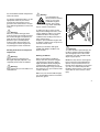
3URSHU&ORWKLQJ
Clothing must be sturdy and snug-fitting,
but allow complete freedom of movement. Avoid loose-fitting jackets, flared
or cuffed pants, scarfs, unconfined long
hair or anything that could be drawn into
the air intake.
Wear overalls or long
pants to protect your legs.
Do not wear shorts.
Use of gloves when
working with the mistblower is recommended.
Good footing is most important. Wear
sturdy shoes with nonslip soles.
:DUQLQJ
To reduce the risk of injury associated
with the inhalation of dust, use a face
filter mask. When using the mistblower,
follow all of the chemical manufacturers
instructions with respect to proper eye,
skin, nose and mouth protection. When
working in greenhouses, make sure they
are well ventilated and, if necessary
wear a respirator.
:DUQLQJ
Proper eye protection is a must. Even
though the discharge is directed away
from the operator, ricochets and
bounce-backs can occur during mistblower operations.
Never operate a mistblower
unless wearing goggles or
properly fitted safety glasses
with adequate top and side
protection which comply with
ANSI Z 87.1 (or your applicable national standard).
7+(0,67%/2:(5
For illustrations and definitions of the
mistblower parts see the chapter on
"Parts and Controls"!
:DUQLQJ
Never modify a mistblower in any way.
Only attachments supplied by STIHL or
expressly approved by STIHL for use
with the specific STIHL mistblower
models are authorized. Although certain
unauthorized attachment are useable for
the STIHL mistblower, their use may be
extremely dangerous.
Fellow workers must also wear eye protection.
Mistblower noise may damage your
hearing. Wear sound barriers (ear plugs
or ear mufflers) to protect your hearing.
Continual and regular users should have
their hearing checked regulary.
Cloth soaped with chemical solutions
has to be changed immediately.
7+(86(2)7+(0,67%/2:(5
7UDQVSRUW
Always turn off the engine before taking
the machine off your back and putting it
down. When transporting your unit in a
vehicle, properly secure it to prevent
turnover, fuel spillage and damage to
the machine.
:DUQLQJ
Before starting work, always inspect the
rubber buffers which connect the engine
to the pack frame. If the buffers are torn
or damaged, they should be replaced by
your STIHL dealer. Failure of one or
more buffers may cause the engine or
fuel tank to hit or rub against other parts,
and may lead to serious injury from increased vibrations or from fire as the
result of fuel leakage.
Adjust carrying harness to suit your size
before starting work.
)XHOLQJ
This STIHL unit uses an oil-gasoline
mixture for fuel (see the chapter on
"Fuel" of your owner‘s manual).
:DUQLQJ
Gasoline is an extremely
flammable fuel. If spilled
or ignited by a spark or
other ignition source,
it can cause fire and
serious burn injury or property damage.
Use extreme caution when handling
gasoline or fuel mix.
Do not smoke or bring any fire or flame
near the fuel.
)XHOLQJLQVWUXFWLRQV
Fuel your machine in well-ventilated
areas, outdoors only. Always shut off the
engine and allow it to cool before
refueling. Relieve fuel tank pressure by
loosening fuel cap slowly. Never remove
fuel filler cap while engine is running.
Select bare ground for fueling and move
at least 10 feet (3 m) from the fueling
spot before starting the engine. Wipe
off any spilled fuel before starting your
mistblower and check for leakage.
Always tighten fuel filler cap securely
after fueling.
:DUQLQJ
To reduce the risk of serious injury from
burns, never attempt to refuel the unit
until it has been completely removed
from the operator.
:DUQLQJ
Check for fuel leakage while refueling
and during operation. If fuel or oil
leakage is found, do not start or run the
engine until leak is fixed and spilled fuel
has been wiped away. Take care not to
get fuel on your clothing. If this happens,
change your clothing immediately.
Always store gasoline in approved
container.
:DUQLQJ
Unit vibrations can cause an improperly
tightened fuel cap to loosen or come off
and spill quantities of fuel.
In order to reduce risk of
fuel spillage and fire,
tighten fuel cap by hand
with as much force as
possible.
6WDUWLQJ
You should always inspect your unit
before starting it. Make sure the controls
and safety devices are working properly.
:DUQLQJ
Your mistblower is a one-person
machine. To reduce the risk of eye or
other injury from thrown objects, insure
that bystanders are at least 50 feet (15m)
away during use.
Stop the engine immediately if you are
approached.
The assistance of another person may
be needed in placing the unit on your
back after starting. In order to reduce the
risk of injury to the assistant from thrown
objects or from contact with fumes, the
engine should be kept at idle speed
during this brief period, and your
assistant should not stand in the area of
the outlet nozzle or exhaust. Otherwise,
For specific starting instructions, see the
appropriate section of your owner‘s
manual. Place the machine on firm
ground or other solid surface in an open
area. Maintain good balance and secure
footing.
:DUQLQJ
When you pull the starter grip, don‘t
wrap the starter rope around your hand.
Do not allow the grip to snap back, but
guide the starter rope slowly back to
permit the rope to rewind properly.
Failure to follow this procedure may
result in injury to hand or fingers and
may damage the starter mechanism.
:RUNLQJLQVWUXFWLRQVDQGLPSRUWDQW
DGMXVWPHQWV
:DUQLQJ
Never operate your machine if it is
damaged, improperly adjusted or not
completely and securely assembled.
:DUQLQJ
Start and operate your unit outdoors in a
ventilated area.
:DUQLQJ
Your mistblower produces poisonous exhaust
fumes as soon as the
combustible engine is
running. These gases
(e.g. carbon monoxide)
may be colorless and odorless.
To reduce the risk of serious or fatal
injury from breathing toxic fumes, never
run the mistblower indoors or in poorly
ventilated locations. Ensure proper
ventilation when working in trenches or
other confined areas.
Keep the space behind the engine clear
at all times to allow for the escape of hot
and toxic exhaust fumes.
Operate your machine under good
visibility and daylight conditions only.
Work carefully.
:RUNLQJ&RQGLWLRQV
When working with the mistblower,
always wear it on your back using the
carrying harness. Wrap your fingers
tightly around the handle, keeping the
control handle cradled between your
thumb and forefinger. Keep your hand in
this position to have your machine under
control at all times.
353BA038 LÄ
the unit should be started and operated
without assistance.
:DUQLQJ
To reduce the risk of personal injury, do
not direct air blast towards bystanders,
since the high pressure of the air flow
could injure eyes and could blow small
objects at great speed.
Mistblowers may also be used in greenhouses which are well ventilated if the
operator can protect himself from any
harmful effects through the use of proper
eye, skin, nose and mouth protection.
Breathing exhaust fumes or toxic chemicals in mist can cause serious or fatal
injury.
Make sure your control handle and grip
is in good condition and free of moisture,
pitch, oil or grease.
:DUQLQJ
Never insert any foreign object into the
air intake of the machine or into the
nozzle of the mistblower. It wil damage
the fan wheel and may cause serious
injury to the operator or bystanders as a
result of the object or broken parts being
thrown out at high speed.
Do not place the mistblower on the
ground when operating at high speed,
because small objects such as sand,
gras, dust, etc. may be pulled into the air
intake and damage the fan wheel.
In the event of the machine catching fire
(for what ever reason) throw it off quickly
by releasing the spring catches on both
sides of the harness.
In an emergency, you may slip out of the
harness and throw off the machine
quickly by first releasing the lap belt on machines that are so equipped and then lifting the tabs of the two sliding
harness adjusters to slacken the shoulder straps. Try this procedure a number
of times before using the machine in
order to become accustomed with it.
Pay attention to the direction of the wind,
i.e., do not work against the wind.
To reduce the risk of stumbling and loss
of control, do not walk backward while
operating the machine.
Pay attention to the direction of the wind,
i.e. do not work against the wind. Do not
direct air blast towards bystanders.
2SHUDWLQJ,QVWUXFWLRQV
The mistblower may be used only for the
operations described in your manual.
8VHRI&KHPLFDOVZLWK0LVWEORZHU
:DUQLQJ
Exercise extreme caution when handling
chemicals. Follow all safety precautions
and instructions laid down by the manufacturer. Avoid contact with chemicals
and chemical solutions. Be sure the mistblower is the proper tool for the job.
:DUQLQJ
Do not spray flammable liquids; such as
gasoline or paint thinner. Such substances create a risk of fire or explosion and
may damage the mistblower. Do not
spray caustic or acid solutions. Contact
with such substances may cause
serious or fatal injury or damage the property, including the mistblower.
:DUQLQJ
When spraying, stand so that the wind
blows the spray away from you and bystanders. Keep children and pets away
from areas that have just been sprayed.
:DUQLQJ
Always empty and clean the liquid container after each use. Residual chemicals
may have undesirable effects during
subsequent spraying with a different
type of chemical (e.g., residual herbicide
may damage or kill plants being sprayed
with a pesticide). It is best to fill the container with clean water and let it drain
out with the tap open. Be cautious where
you drain the liquid during the cleaning
process.
Never store liquid in the container for
more than one day.
8VHRIWKH0LVWEORZHU
The mistblower can be used for spraying
chemicals an liquids to control pests and
weeds in fruit and vegetables gardens,
on trees and bushes, citrus, coffee,
tobacco, cotton and many other areas.
It is also useful in the maintenance of
young trees, controlling the bark beetle
and other plant diseases.
)LOOLQJWKH&RQWDLQHU
To reduce the risk of contaminating the
surrounding environment, be careful not
to overfill the container with chemical
solution.
If you fill the container with a hose
attached to a water pipe be sure the end
of the hose is out of the solution to
reduce the risk of chemicals being
sucked into the water pipe in the case of
a sudden vacuum.
Calculate the correct amount of chemical solution so that it is used up at one
time.
0$,17(1$1&(5(3$,5$1'
6725,1*
0DLQWHQDQFHUHSODFHPHQWRUUHSDLU
RIWKHHPLVVLRQFRQWUROGHYLFHVDQG
V\VWHPVPD\EHSHUIRUPHGE\DQ\
QRQURDGHQJLQHUHSDLUHVWDEOLVKPHQW
RULQGLYLGXDO+RZHYHULI\RXFODLP
ZDUUDQW\IRUDFRPSRQHQWZKLFKKDV
QRWEHHQVHUYLFHGRUPDLQWDLQHGSUR
SHUO\RULIQRQDSSURYHGUHSODFHPHQW
SDUWVZHUHXVHG67,+/PD\GHQ\
ZDUUDQW\
Check fuel filler cap for leaks at regular
intervals. Use the specified spark plug
and make sure it and the ignition lead
are always in good condition.
Use only identical STIHL replacement
parts for maintenance and repair.
Use of parts manufactured by others
may cause serious or fatal injury.
Remember that the risk of forest fires is
greater in hot weather. Use the spark
arresting muffler supplied with the unit.
Never touch a hot muffler or burn will
result.
Follow the maintenance and repair
instructions in the appropriate section of
your owner’s manual. Refer to the
maintenance chart at the end of this
manual.
:DUQLQJ
A worn or damaged muffler is a fire
hazard and may cause loss of hearing.
Check to see that the muffler is in good
condition. The mistblower must not be
operated if the muffler is not functioning
properly or has been removed.
:DUQLQJ
Always stop the engine and make sure
that the fan is stopped before doing any
maintenance or repair work or cleaning
the mistblower. Do not attempt any maintenance or repair work not described in
your owner’s manual. Have such work
performed at your STIHL service shop
only.
:DUQLQJ
In order to reduce the risk of fire, do not
modify or remove any part of the muffler
or spark arrestor.
Tighten all nuts, bolts and screws except
the carburetor adjustment screws after
each use.
Keep spark plug and wire connection
tight and clean. The spark plug electrode
gap should be checked with a feeler
gauge at least every 50 operating hours
and reset if necessary. Fit a new spark
plug if the electrodes are badly pitted.
For any maintenance please refer to the
maintenance chart DQGWRWKHZDUUDQW\
VWDWHPHQW near the end of this manual.
Store mistblower in a dry, high or locked
location place and out of reach of
children.
Before storing for longer than a few
days, always empty the fuel tank.
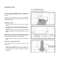
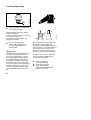
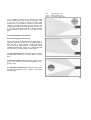
Assembly of Unit
Top:
Ellbow fitted to fan housing
Center: Spraying attachment fitted
Bottom: Stop cock lever in vertical position
The unit is partly disassembled for ease of shipment and
must be completely assembled before it is used for the
first time.
The tools on the underside of the unit (1 combination
wrench and 1 carburetor screwdriver) should be used for
the assembly work.
Mounting the elbow
- Line up the stops on the elbow (1) and fan housing
stub (2).
- Push the elbow (1) into the stub (2) as far as it will go.
- Fit a nut (3) into each of the molded hexagon seats on
the stub.
- Insert a screw (4) into each nut from the other side and
tighten moderately (it must still be possible to turn the
elbow).
Important: The throttle cable with integrated stop switch
wire is already connected to the control handle and the
engine and must not be kinked during assembly.
- Attach throttle cable with the retainer (5) to the pleated
hose.
Mounting the spraying attachment
Insert extension tube (12) into the pleated hose (7) as far
as it will go.
- Rotate the pleated hose (7) to the left
(counterclockwise) as far as the stop and leave it in
that position until you have completed the following
adjustments.
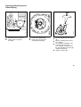
11
- Rotate the control handle (10) to the left (counterclockwise)
until it is horizontal.
- Rotate the extension tube 12 to the left (counterclockwise)
until the metering unit (13) points in the same direction as
the control handle.
- Tighten the clamp screw (11). (Observe instructions in
chapter "Adjusting the control handle")
- Push the free end of the liquid hose (14) over the stub on
the stop cock (15) and secure in position with the hose clip
(16).
- Secure liquid hose to the pleated hose with the retainer (5).
- Close the stop cock (move lever to vertical position).
Fill up with spray mix and check all hose connections for
leaks.
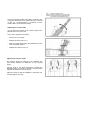
12
Top:
Range of rotation of tube
Center: Range of adjustment of control handle
Bottom: Pulling ends of straps downward (left)
Lifting tabs of strap adjusters (right)
The pivot-mounted pleated hose allows the blower tube
or spraying attachment to be rotated about 90° to the left
or right (i.e. counterclockwise or clockwise) from the
center position (control handle vertical).
Adjusting the control handle
You can adjust the position of the control handle on the
pleated hose to suit your reach.
Carry out the adjustment as follows:
- Put the unit on your back.
- Release the clamp screw (11).
- Slide the control handle along the pleated hose to the
most comfortable position.
- Retighten the clamp screw (11).
Adjusting the harness straps
The harness straps are attached to the backplate and
have sliding adjusters for adjustment to any required
length.
Pull the ends of the straps downward to tighten the
backplate against your back. Lift the tabs of the two sliding
adjusters to slacken the harness straps.
Adjust the straps so that the backplate is held firmly and
securely against your back.
13
)XHO
This engine is certified to operate on
unleaded gasoline and with the
mix ratio 50:1.
We recommend STIHL 50:1 two-stroke
engine oil since it is specially formulated
for use in STIHL engines.
Your two-stroke engine requires a
mixture of brand-name gasoline and
quality two-stroke engine oil with the
classification TC.
Do not use BIA or TCW (two-stroke
water cooled) mix oils!
Use regular branded unleaded gasoline
with a minimum octane rating of
90 RON (U.S.A./Canada: pump octane
min. 89!). If the octane number of the
regular grade gasoline in your area is
lower use premium unleaded fuel.
Fuel with a lower octane rating may
result in preignition (causing "pinging")
which is accompanied by an increase in
engine temperature. This, in turn,
increases the risk of the piston seizure
and damage to the engine.
The chemical composition of the fuel is
also important. Some fuel additives not
only detrimentally affect elastomers
(carburetor diaphragms, oil seals, fuel
lines etc.), but magnesium castings as
well. This could cause running problems
or even damage the engine. For this
reason it is essential that you use only
name branded fuels!
Use only STIHL two-stroke engine oil or
equivalent branded two-stroke aircooled engine oils with the classification
TC for mixing.
Take care when handling gasoline.
Avoid direct contact with the skin and
avoid inhaling fuel vapour.
The canister should be kept tightly
closed in order to avoid any moisture
getting into the mixture.
The fuel tank and the canister in which
fuel mix is stored should be cleaned
from time to time.
)XHOPL[DJHV
Only mix sufficient fuel for a few days
work, not to exceed 3 months of storage.
Store in approved safety fuel-canisters
only. When mixing, pour oil into the
canister first, and then add gasoline.
Gasoline
Oil (STIHL 50:1 or
equivalent branded TC oils)
US gal.
US fl.oz
1
2 1/2
5
2.6
6.4
12.8
Dispose empty mixing-oil canisters only
at authorized disposal locations.
Before fueling, clean the filler cap
and the area around it to ensure that no
dirt falls into the tank.
Always thoroughly shake the mixture in
the canister before fueling your machine.
353BA009
353BA008
)XHOLQJ
Change the fuel pick up body every year.
Before storing your machine for a long
period, drain and clean the fuel tank and
run engine until carburetor is dry.
:DUQLQJ
In order to reduce the risk of burns or
other personal injury from escaping gas
vapor and fumes, remove the fuel filler
cap carefully so as to allow any pressure
build-up in the tank to release slowly.
:DUQLQJ
After fueling, tighten fuel cap
as securely as possible by hand.
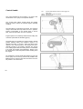
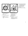
Control Handle
Top:
Control handle with stop switch, throttle trigger and
setting lever
Center: Setting lever in lower end position
Bottom: Stop cock lever
The control handle has two functions. It is used to aim
the airstream or the spray in the required direction.
The controls (stop switch, throttle trigger and setting
lever) are used to select the required engine operating
condition.
The stop switch (1) shuts down the engine. The engine is
ready to start when the stop switch is in the "I" position.
Ignition is interrupted, i.e. the engine stops or will not
start, when the stop switch is in the "0" position.
Engine speed can be infinitely varied between idling and
maximum speed with the throttle trigger (2).
The setting lever (3) enables any engine speed or throttle
position between idling and maximum speed to be
selected and held. To do this, swing the setting lever
upward to the required position. The setting lever automatically remains in the position. selected. The engine
runs at idling speed when the setting lever is moved back
to its lower end position (see illustration). Always move
the setting lever to this end position before shutting down
the engine.
The mistblower's control handle also features a stop cock
for the spray mix. Its lever (4) must be set parallel to the
pleated hose for maximum flow and returned to the vertical position to shut off the flow.
16
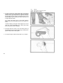
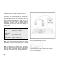
Starting
Top:
Throttle trigger and setting lever in "start" position
Center: Rotary choke knob in "cold start" position
Bottom: Rotary choke knob in "warm start" position
Before starting, place the unit on a clear patch of ground.
Make sure you have a firm foothold, keep a firm grip on
the machine and check that there are no objects which
could be sucked in by the fan (between engine and
backplate).
1.
Starting procedure
1.1 Slide the stop switch (1) to "I". Move the setting lever
(3) to the midway position between the two end
stops. The throttle trigger (2) is now in the "starting
throttle" position.
1.2 If the engine is cold: Turn the rotary choke knob (4)
in the direction of the arrow l (choke).
1.3 If the engine is warm: Turn the rotary choke knob (4)
in the opposite direction to the arrow.
Note: This procedure also applies if the engine has
been running but is still cold.
17
Top:
Starting
Center: Setting lever in Lower end position
Bottom: Stop switch on "STOP"
2. To start, hold the top of the machine with your left hand
and put one foot on the base plate to prevent it slipping.
Pull the starter grip slowly with your right hand until you
feel it engage and then give it a brisk strong pull. Do not
pull the starter rope out more than about 70 cm (27") as
it might otherwise break.
Do no allow the starter rope to snap back. Guide it
slowly back into the housing so that it can rewind correctly.
Continue cranking the engine until it begins to fire. Then
open the choke immediately (turn rotary knob away
from arrow) and continue cranking.
3. Once the engine is running, move the setting lever (3)
immediately to its lower end position (ill.) so that the engine can settle down to idle speed.
4. To stop the engine, slide the stop switch (1) to "STOP".
18
Air Filter
Component parts in correct sequence
Erratic idling behavior; poor acceleration
Idle setting too lean; turn low speed adjusting screw (2)
counterclockwise until engine runs and accelerates
smoothly.
Exhaust smokes at idle speed
Idle speed setting too rich; turn low speed adjusting
screw (2) clockwise until engine speed drops. Then turn
screw back one quarter turn and check that engine still
accelerates smoothly when you open the throttle.
A correction at the low speed adjusting screw usually
necessitates a change in the setting of the idle speed
adjusting screw (3).
Apart from minor adjustments, you should leave all carburetor setting and repair work to your STIHL dealer. STIHL
dealers have trained staff and all the necessary servicing
tools and equipment.
The purpose of an air filter is to prevent any dust and dirt
in the intake air from entering the carburetor and thus
protect the moving parts of the engine from abnormal
wear. Dirty air filters reduce engine power, increase fuel
consumption and make starting more difficult.
The air filter must, therefore, be cleaned or replaced
when there is a noticeable loss of engine power.
Before removing the air filter, close the choke (turn rotary
knob in direction of arrow) to prevent dirt falling into the
carburetor. Remove the screw (1) and take off the filter
cover (2) and the filter (3)
Wash the filter (3) in a fresh, non-inflammable cleaning
solution and allow to dry.
Never refit a damaged filter element, always fit a new one.
19
$GMXVWLQJWKH&DUEXUHWRU
L
0RWRUPDQDJHPHQW
Exaust emissions are controlled by the
design of the fundamental engine parameters and components (e.g. carburation, ignition, timing and valve or part
timing) without the addition of any major
hardware.
The carburetor comes with a standard
setting.
This is the optimum setting to ensure
your machine will operate reliably with
the lowest possible emission under most
operating conditions.
6WDQGDUGVHWWLQJ
If it is necessary to readjust the carburetor from scratch, first carry out the
standard setting.
Turn
+ high speed adjusting screw and
/ low speed adjusting screw
counterclockwise (richer)
or as far as stop.
If you don‘t have a tachometer, do not
set the highspeed adjusting screw any
leaner by turning it beyond the standard
setting.
2SHUDWLRQDWKLJKDOWLWXGH
PRXQWDLQV
Slight correction PD\ be necessary.
Use a WDFKRPHWHU to set the high speed
adjusting screw + to obtain the highest
possible engine speed. From that
position, turn the high speed adjusting
screw + 1/8 counterclockwise (richer)
or as far as stop. Avoid risk of engine
damage which can be caused by lack of
lubrication and overheating Check air filter and clean it if
necessary.
Set idle speed correctly.
Warm up the engine.
Turn the high speed adjusting
screw + and low speed adjusting
screw / clockwise (leaner) at
higher altitudes.
Turn the screws very slowly and
carefully - slight changes have a
noticeable effect on the engine’s
running behavior.
•
•
•
&RUUHFWLRQVWRKLJKVSHHGDGMXVWLQJ
VFUHZ
The high speed adjusting screw +
alters the power output and
maximum off-load engine speed.
If you turn this screw too far clockwise and make the setting too lean,
there is a risk of engine damage.
L
LA
353BA023
H
6HWWLQJLGOHVSHHG
It is usually necessary to change
the setting of the idle speed
adjusting screw /$ after
every correction to the low
speed adjusting screw /.
(QJLQHVWRSVZKLOHLGOLQJ
Turn the idle speed adjusting
screw /$ clockwise until
the engine runs smoothly.
(UUDWLFLGOLQJEHKDYLRUSRRU
DFFHOHUDWLRQ
Idle setting is too lean.
Turn the low speed adjusting screw
/ counterclockwise until engine
runs and accelerates smoothly.
2SHUDWLQJ,QVWUXFWLRQV
6WRULQJWKH0DFKLQH
'XULQJEUHDNLQSHULRG
For periods of about 3 months or longer:
A factory new machine should not be
run at high revs (full throttle off load) for
the first three tank fillings. This avoids
unnecessary high loads during the
break-in period.
As all moving parts have to bed in
during the break-in period, the
frictional resistances in the engine
are greater during this period.
The engine develops its maximum
power after about 5 to 15 tank fillings.
•
•
•
•
•
Drain and clean the container.
Drain and clean the fuel tank.
Run engine until carburetor is dry this helps prevent the carburetor
diaphragms sticking together.
Thoroughly clean the machine pay special attention to the
cylinder fins and air filter.
Store the machine in a dry, high
or locked location - out of the
reach of children and other
unauthorized persons.
'XULQJRSHUDWLRQ
After a long period of full-throttle
operation, allow engine to run for a while
at idle speed so that the heat in the
engine can be dissipated by flow of
cooling air. This protects enginemounted components (ignition,
carburetor) from thermal overload.
$IWHUILQLVKLQJZRUN
Storing for a short period:
Wait for engine to cool down. To avoid
condensation, fill the fuell tank and
keep the unit in a dry place until you
need it again.
Storing for an long period:
see chapter "Storing the Machine".
A
•
000BA039 KN
&KHFNLQJ6SDUN3OXJ
Use only resistor type spark plugs
of the approved range.
1
•
Fit a new spark plug after
approx. 100 operating hours or earlier if the electrodes are
badly eroded.
:DUQLQJ
To reduce the risk of fire and burn injury,
use only spark plugs authorized by
STIHL (see “Specifications”). Always
press spark plug boot snugly onto
spark plug terminal of the proper
size. (Note: If terminal has detachable
SAE adapter nut, it must be attached.)
A loose connection between spark plug
terminal and ignition wire connector in
the boot may create arcing that could
ignite combustible fumes and cause a
fire.
000BA036 TR
Rectify problems which have caused
fouling of spark plug:
Incorrect carburetor setting, too much oil
in fuel mix, dirty air filter,
unfavorable running conditions, e.g.
operating at part load.
Wrong fuel mix (too much engine oil in
the gasoline), a dirty air filter and
unfavorable running conditions (mostly
at part throttle etc.) affect the condition of
the spark plug. These factors cause
deposits to form on the insulator nose
which may result in trouble in operation.
If engine is down on power, difficult to
start or runs poorly at idling speed,
first check the spark plug.
•
•
•
Remove spark plug see chapter “Starting”:
Clean dirty spark plug.
Check electrode gap it should be 0.5mm/0.02" $ readjust if necessary.
5HSODFLQJ6WDUWHU5RSHDQG
5HZLQG6SULQJ
6
1
1
2
7
•
•
Remove the three screws .
Lift the starter cover off
the engine.
353BA041 KN
353BA027
1
•
•
Remove the spring clip .
Remove the rope rotor with
washer and pawl .
•
•
•
•
Ease the cap out of the starter
grip.
Remove remaining rope from the
rotor and grip.
Tie a simple overhand knot in the
end of the new starter rope 1113 195 8200 - and then thread
the rope through the top of the grip
and the rope bush .
Refit the cap in the grip.
5HSODFLQJDEURNHQUHZLQGVSULQJ
353BA036 T
•
•
•
•
Thread the rope through the rotor
and secure it with a simple overhand knot.
•
•
•
•
•
Coat rope rotor bearing bore with
non-resinous oil.
Slide rotor onto starter post turn it back and forth so that anchor
loop of rewind spring engages Refit the pawls in the rotor Fit the washer on the starter post
Use screwdriver or suitable pliers
to install spring clip on starter
post and over the pawl pegs the spring clip must point in
clockwise direction see illustration.
Lubricate the new spring with a few
drops of non-resinous oil Remove the rope rotor see "Replacing Starter Rope" Remove parts of old spring.
•
•
•
•
Fit new spring housing - bottom
plate must face downward.
Engage outer spring loop over the
lug.
Refit the rope rotor.
Go to "Tensioning rewind spring".
If the spring has popped out and
uncoiled:
Refit it in the counterclockwise
direction - start outside and work
inward.
353BA030
353BA029
•
•
•
When starter rope is fully extended
it must be possible to rotate the rotor
at least another half turn. If this is
not the possible, the spring is overtensioned and could break
Take off one turn of the rope.
Fit the fan housing on the
crankcase.
Tighten down the screws firmly.
Set the Master Control lever to 7HQVLRQLQJUHZLQGVSULQJ
Make a loop in the unwound starter
rope and use it to turn the rope
rotor six full revolutions in the
direction of the arrow
Hold the rotor steady straighten the twisted rope Release the rotor Let go of rope slowly so that it winds
onto the rotor.
The starter grip must sit firmly in the
rope guide bush. If the grip droops
to one side: Increase spring tension
by one additional turn.
•
•
•
•
Special accessories
Lap belt
The lap belt is standard on some models and can be
retrofitted to all mistblowers. It ensures that the backplate
is always positioned snugly against the user's back.
Back padding
Additional back padding is available to further enhance
wear comfort. It is attached to the backplate next to the
standard padding.
Dusting and spreading
attachment (SR 320, SR 400)
Equipped with this attachment, sprayers can apply
chemicals and other substances which come in
granulated or powder form (e. g. fertilizers, grass seed
etc.).
Booster pump kit (SR 320, SR 400)
The booster pump constantly agitates the spray mix and
ensures a uniform spray rate, regardless of the position in
which the mistblower tube is held.
ULV rotary nozzle kit (SR 320, SR 400)
Units equipped with the ULV rotary nozzle are capable of
spreading very small quantities of special chemicals. To
guarantee constant spray rates with the ULV rotary
nozzle, the unit has to be additionally equipped with the
booster pump kit.
26
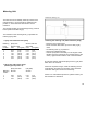
Metering Unit
Nozzle with metering unit
The flow rate can be infinitely varied by means of the
metering knob (1) on the nozzle (2). Metering knob
position "1" is the minimum flow rate and "6" the
maximum.
The required number on the metering knob (1) must be
lined up with the molded lug (3).
The numbers on the metering knob (1) represent the
following spray rates:
Checking the metering unit (without booster pump)
1. Spray rate without booster pump
Metering
knob
position
Spray rate
SR 320, SR 400
without baffle
with baffle
I/min
(US gal/h) I/min
(US gal/h)
1
2
3
4
5
6
0.13
0.61
1.27
1.92
2.49
2.78
(2.0)
(9.5)
(20.2)
(30.5)
(39.2)
(43.9)
0.14
0.71
1.33
2.09
2.67
3.03
(2.3)
(11.1)
(21.0)
(33.2)
(42.4)
(47.5)
- Place the unit on the ground.
- Fill the container with water up to the 10 liter (2 gal)
mark.
- Set metering knob (1) to position 6.
- Start the unit (baffle removed).
- Hold the spray tube horizontally, run the engine at full
throttle, spray the contents of the container down to the
5 liter (1 gal) mark and make a note of the time taken.
The SR 320 and SR 400 should spray 5 liters (1 gal) fluid
within 80 to 100 seconds.
2. Spray rate with booster pump
(metering knob position 6)
Metering
nozzle
1
2
3
Spray rate I/min
SR 320
(US gal/h)
SR 400
0.53
1.42
2.44
0.57
1.54
2.32
(8.3)
(22.5)
(38.8)
(9.1)
(24.5)
(36.8)
If the time required is longer, check the metering unit for
contamination and clean it if necessary. Also check the
carburetor setting and correct it as necessary.
If there is no noticeable improvement, please contact your
STIHL dealer for assistance.
27
Notes on Use of Mistblowers
Comparison of principles of backack mistblowers and
backpack high-pressure sprayers
The methods of operation of low-volume mistblowers and
high-pressure sprayers are fundamentally different.
In the case of the high-pressure sprayer the carrier liquid
in the solution serves as the transport medium for the
active ingredient. The solution is applied at a comparatively high pressure produced by a high-pressure pump and a
small-bore nozzle. The size of the droplets formed in this
process is generally in the order of 300 to 400 um. Owing
to the resultant small number of droplets, which have to
wet the same crop area as in low-volume mistblowing, the
active ingredients can only be applied in highly diluted
form with a lot of carrier liquid.
The only way to produce smaller droplets is to considerably increase pump pressure and use much higher driving
power - both these factors increase the complexity of the
unit. The energy required to accelerate water is relatively
high. For this reason the efficiency of high-pressure spray
ers is generally low. The units themselves are quite heavy
and have a short range of only 30 to 50 cm (measured
from the nozzle).
In the mistblower, air is used as an additional transport
medium for the active ingredient. An engine-powered fan
produces a powerful, concentrated airstream to which the
solution (active ingredient in carrier liquid) is added via a
metering system. The solution is atomized into very fine
droplets and discharged at high velocity by the airstream.
Depending on the design of the atomizer, it is possible to
28
produce droplets with a size of approx. 50 to 250 pm. The
large number of fine droplets and the airstream's excellent
penetration of the crop ensure high efficiency. This means
that the quantity of carrier liquid (normally water) can be
reduced, i. e. a higher concentration of active ingredient
can be used in the solution.
Considerably less energy is required to accelerate air.
Therefore, low-volume mistblowers, are more efficient
(long range with relatively low driving power and low
weight) and can cover a larger area per unit time.
Advantages of low-volume mistblowers over high-pressure
sprayers:
•
•
•
•
•
•
•
High efficiency as a result of large area coverage per unit
time.
Less physical effort - high-performance mistblowers are
relatively compact and lightweight.
High wetting capacity as a result of high kinetic energy of
droplets.
Very fine and uniform distribution of active ingredient for
better biological effectiveness.
Active ingredient is saved by reducing losses due to
solution dripping from crop.
Better adhesive properties and resistance to rain.
No growth inhibition caused by clogging the foliage.
•
•
•
Long horizontal and vertical spraying range.
Working time is saved not only during the actual application, but also during the preparations, i.e. less spray
solution has to be transported to the site and fewer refilling stops are required.
The formation of very fine droplets enables the concentration of active ingredient to be increased and the total
amount of spray solution to be reduced - a water saving of up to 80%.
Choice of spray chemical
In the case of plant protection products preference should
be given to biological products which do not harm useful
insects. Local plant protection services and other experts
provide information on the best type, application and concentration (mix ratio) of products.
Note: Never apply the active ingredient in concentrated form
(undiluted).
Step 2:
Refer to the instructions for use supplied with the active in
gredient to establish the required quantity (usually quoted
for 1 hectare [ha]) and the concentration (mix ratio) of the
solution. Manufacturers normally quote the concentration
required for high-pressure spraying. Low-volume mistblo
wing uses only about one quarter of this quantity. If the in
structions for use do not contain any data for low-volume
mistblowing, reduce the amount of carrier liquid (water)
accordingly to suit the required concentration of active in
gredient. This produces the quantity of solution required
for treating 1 ha.
Step 3:
Multiply the quantity of solution required for 1 ha by the
surface area determined in step 1. The result is the quan
tity of solution needed for the surface area to be treated.
Example:
Determining and mixing required quantity of solution
Step 1:
Determine the surface area to be treated in square meters
2
(m ). In the case of ground crops, simply multiply the
length of the field by its width. The surface area of highgrowing plants is calculated roughly by measuring the
length of the rows and the average height of the foliage.
The result is multiplied by the number of rows and then by
two - if both sides have to be treated.
A field with a length of 120 m and width of 30 m is to be
treated with a pesticide. According to the maker's instruc
tions, 0.6 liters are required per hectare to obtain a con
centration of 0.1 % for high-pressure spraying.
A concentration of 0.1 % represents a mix ratio of
1 part pesticide to 1,000 parts water.
29
In this case 0.6 litres pesticide would have to be mixed
with 600 litres water to make up the spray solution.
However, in low-volume mistblowing only one quarter of
the water quantity is required for the same amount of
pesticide. This means that the concentration used is four
times higher than for high-pressure spraying. The 0.6
litres pesticide therefore have to be mixed with only 150
litres water. That is the quantity of solution required for
mistblowing 1 hectare. Finally, this quantity has to be
multiplied by the area to be treated in our example, i.e.
0.36 ha. The total quantity of solution to be applied to the
field is 54 litres.
Calculation
Area:
Solution/ha:
(acre):
2
120 m • 30 m = 3,600 m
2
2
3,600 m : 10,000 m /ha = 0.36 ha
0.6 l: 0.001 : 4 = 150 l
Required quan
tity of solution: 150 l/ha • 0.36 ha = 54 l
See enclosed graph 0457 352 0100
Note: If the area to be treated is smaller than 1 hectare,
the quantity of solution required is less than the quantity
of solution per hectare (acre).
Note: The increase in the strength of the mixture by a
factor of 4 was assumed for the purposes of this example.
Other mix ratios are possible in practical applications on
the basis of empirical values, special requirements or
explicit instructions.
30
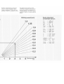
The graph makes it easier to determine the quantity of
solution required. You can use a ruler and pencil to mark
in your own applications.
Preparations for mistblowing
Before starting work it is necessary to determine the following points, which affect the liquid discharge rate per unit
area and thus the distribution of active ingredient in the
crop:
•
•
•
•
Working width
Walking speed
Unit's discharge rate per unit time
Position of spray tube (angle from horizontal)
Among other factors, the working width is dependent on
the crop and is determined by the distance between rows
of trees, shrubs and bushes. In the case of low-growing
crops, the best working width is about 4 m, but can be up
to 5 m if the user adjusts his walking speed accordingly.
The working width should be marked with stakes to avoid
any deviation.
The walking speed can vary greatly from user to user. For
this reason it is advisable to do a trial run with the machine
fueled and the container filled with water, and make a note
of the time taken (stop watch). While walking, the spray
tube should be operated as it will be during the real run
described below.
Rule of thumb: Normal length of stride is 0.7 to 0.9 m, but
can be up to 1.0 m. Measuring the distance is better than
counting the number of steps. Dividing the distance in
meters by the time in minutes produces the walking speed
in meters or yards per minute (m/min)
The discharge rate per unit time liters/min is infinitely
variable on the mistblower's metering unit. The required
discharge rate is determined by the area to be treated, the
quantity of solution, the working width and the walking
speed. It can be calculated with the aid of the following
equation:
Vsol (I) • VW (m/min) • b (m)
2
A (m )
=Vdis (I/min)
Where:
Vsol = Quantity of solution
VW = Walking speed
b
= Working width
A
= Area
Vdis = Discharge rate
This trial run is also used to check the working width, i.e.
the greater the width, the slower the walking speed. Check
the distance walked in one minute.
31
Important:
All values must be inserted in the equation in the units specified. Note that hectares have to be multiplied by 10,000
to obtain square meters. Assuming a working width of 3 m
and a walking speed of 60 m/min, the calculation of the
above example would be as follows:
54 I • 60 m • 3 m
1 min • 3,600 m
2
= 2.7 I/min
The metering unit on the mistblower would therefore have
to be set to 2.7 I/min. It this rate is not marked directly on
the scale, select an intermediate setting. The settings of
the metering unit and the related discharge rates are given
in the mistblower's instruction manual. The following table
can also be used as a rough guide for selecting discharge
rates. If the required quantity of solution is not mentioned,
use the next higher and lower values in the table to work
out the correct proportions for your application. Similarly,
the table shows the quantities of solution required per hec
tare (acre) at different discharge rates and working widths.
They are based on a walking speed of 60 m/min.
32
Discharge
rate (I/min)
0.8
1.6
2.3
2.6
2.9
Solution required at working width
1m
2m
3m
4m
133
267
383
433
483
67
133
192
217
242
44
89
128
144
161
33
67
96
108
121
In our example the quantity of solution per hectare is 150
litres and the working width 3 m. In the "3 m" column, the
value 150 I is between 144 and 161 liters.
The difference between 150 and 161 is about twice as
much as it is between 150 and 144. The metering unit the
refore has to be set somewhere between 2.6 and 2.9. Allo
wing for the proportional difference, the setting should be
2.7, which corresponds to the calculated value.
The mistblower's discharge rate is also affected by the po
sition of the spray tube. The discharge rates quoted
above are averages for the "horizontal" and "30° up" posi
tions. There is a noticeable reduction in discharge rate
when the upward angle of the spray tube is increased, e. g.
mistblowing high trees. STIHL recommends the use of a
pressure pump (special accessory) for applications which
require the spray tube to be held at an upward angle of
more than 30°. It helps maintain a constant discharge rate
in all spray tube positions.
33
Use of mistblower
In mistblowing the solution flows from the container, down
through the open shut-off cock and the metering nozzle to
the spray tube. The jet of solution is injected into the airstream, atomized and discharged. The airstream is permeated more or less uniformly with very fine droplets.
The factors which influence the liquid discharge rate per
unit area are either fixed by the setting (discharge rate per
unit time) or determined by the operator. Walking speed
and working width can vary. These variations can result in
considerable differences in the quantity of active ingredient applied per unit area. In addition, the wetting effect
can be altered by the direction and strength of the wind.
Great care must be taken with active ingredients which
can harm plants and the environment if applied in too high
a dosage. Too low a dosage may fail to achieve the desired
effect.
To limit these variations, always run the mistblower at full
throttle with the shut-off cock fully open. Accelerate the
engine up to full throttle first and then open the shut-off
cock. Note that the discharge rate is controlled by the me
tering unit, not the shut-off cock.
The normal walking speed for low-growing crops is 1 m/s.
It may be necessary to walk slower when mistblowing
higher crops.
To achieve greater working widths or treat open and high
growing crops, the spray tube must be moved quickly
back and forth or up and down. In order to extend the
mistblower's vertical reach (tall trees), the spray tube must
34
be held steady or moved only very slowly to ensure that
the spray mist is properly formed and stable.
Influence of walking speed and working width on
discharge rate and amount of solution needed
Practical experience has shown that walking speed can
vary by 5 to 6 m/min. A slower walking speed means that
it is necessary to reduce the discharge rate or amount of
solution and vice versa. Walking 6 m/min slower than the
specified 60 m/min means a reduction of 10%.
In our example the setting of the metering unit would also
have to be reduced by 10%, from 2.7 to 2.43 I/min. If this
is not done, the quantity of solution required would in
crease 10%, from 54 liters to 59.4 liters.
The variation in working width can be considerable, espe
cially if the field has not be marked with stakes. A reduc
tion of the working width at a given walking speed means
that the discharge rate would have to be' reduced or the
amount of solution increased and vice versa. Reducing the
width by 0.5 m, after having assumed a working width of
3 meters, represents a reduction of 17%.
Top:
Center:
Bottom:
Tapered baffle screen
Deflector baffle screen
Dual defector baffle screen
In our example the setting of the metering unit would
have to be reduced by 17%, from 2.7 to 2.24 I/min. If this
is not done, the quantity of solution required would
increase 17%, from 54 liters to 63.2 liters. If both these
variations occurred at the same time, the setting of the
metering unit would have to be reduced by 27%, from 2.7
to 1.97 I/min, because the quantity of solution required
would otherwise increase 27%, from 54 liters to 68.6
liters.
Use of standard/special accessories
Pressure pump (special accessory)
The pressure pump is recommended for applications in
which the spray tube to be held at an upward angle of
more than 30°. It helps maintain a constant discharge
rate in all spray tube positions. Furthermore, active
ingredients which tend to settle in the container are held
in suspension by constant agitation of the solution.
The tapered baffle screen causes the solution to be discharged finely atomized in a broad, dense and short
cloud.
The deflector baffle screen diverts the spray jet at an
angle. It can be used for under-leaf treatment of lowgrowing crops.
The dual deflector baffle screen splits the spray jet into
two and thus allows two rows of plants to be treated
simultaneously.
35
Detachable nozzle and baffle screens (accessory)
Some important conversion factors
It may be necessary to change the pattern and direction of
the spray jet for certain crops and applications. A detachable nozzle and various baffle screens are available
for this purpose.
1m
1m
1 yd
1 yd
1 ft
1 m/s
1 ft/s
=
=
=
=
=
=
=
1,094
39,370
0,914
3
12
3,28
0,305
yd
in
m
ft
in
ft/s
m/s
1 ha
1 acre
1 ar
1 acre
1l
1I
1I
=
=
=
=
=
=
=
2,470
0,405
0,025
4840
0,264
2,11
33,81
acre
ha
acre
yd
US gal
US pt
fl.oz
1 US gal
1 US gal
1 US gal
= 3,785
= 8
= 128
l
US pt
fl.oz
11/min
1 GPM
= 0,264
= 3,785
GPM
I/min
The detachable nozzle (for older machines) without baffle
screen produces a fine mist with a long range.
ULV rotary nozzle (special accessory)
The STIHL ULV nozzle produces droplets with a size of
about 50 gym. It enables highly concentrated substances
to be applied with very little carrier liquid.
36
Complete machine
Control handle
Air filter
Filter in fuel tank
Fuel tank
Carburetor
Spark plug
Cylinder fins
Spark arresting screen
All accessible screws and nuts
(not adjusting screws)
Container with line
Metering unit
Rubber vibration buffers
The user of this unit should carry out
only the maintenance operations
described in this manual. Other repair
work may be performed only by an
authorized STIHL Service dealer.
Visual inspection (condition, leaks)
Clean
Check operation
Clean
Replace
Check
Replace felt and strainer
Clean
Check idle adjustment
Idle setting
Readjust electrode gap
Clean
Inspect
Clean or replace
Retighten
Visual inspection
Check
Visual inspection
To be replaced only by STIHL dealer
:DUUDQW\FODLPVIROORZLQJUHSDLUV
FDQEHDFFHSWHGRQO\LIWKHUHSDLU
KDVEHHQSHUIRUPHGE\DQDXWKRUL]HG
67,+/6HUYLFHGHDOHUXVLQJRULJLQDO
67,+/VSDUHSDUWV
x
see page:
as required
if damaged
if faulty
monthly
weekly
after each
refueling stop
after finishiing
work or daily
Please note that the following maintenance intervals apply for normal operating
conditions only. If your daily working time is longer than normal or operating
conditions are difficult (very dusty work area) shorten the specified intervals
accordingly.
before
starting work
0DLQWHQDQFH&KDUW
x
x
x
x
x
x
x
x
x
x
x
x
x
13
19
19
15
15
15
20
20
22
x
x
x
x
x
x
27
x
x
x
Original STIHL parts can be identified
by the STlHL part number, the
T logo and the STIHL parts
symbol The symbol may appear
alone on small parts.
Specifications
Engine
STIHL single cylinder two-stroke engine
SR 320
Displacement:
44.9 cm³
(2.74 cu.in)
Bore:
41 mm (1.61 in)
Stroke:
34 mm (1.34 in)
Engine power:
2,0 kW
For US only:
320 L
Bystander noise per ANSI
B 175.2 -1990
70 dB (A)
SR 400
56.5 cm³
(3.45 cu.in)
46 mm (1.81 in)
34 mm (1.34 in)
2,5 kW
Ignition System
Type:
Electronic magneto ignition
(breakerless)
Spark plug (suppressed): NGK BPMR 7 A or
Bosch WSR 6 F
Heat range 200
Electrode gap 0.5 mm (0.02 in)
Spark plug thread:
M 14x1.25;
9.5 mm (0.37 in) long
Fuel System
Carburetor:
Air filter:
Fuel tank capacity:
Fuel mixture:
Spraying and Spreading Attachment
Model
Airflow
Air
Engine
rate/hour
velocity
speed
SR 320
SR 400
3
655 m /h
(385 cfm)
3
715 m
(420 cfm)
Container capacity:
Size of filler
strainer mesh (SR):
Rate of liquid
discharge (SR)
without screen:
with screen:
Quantity remaining
in container (SR):
Spraying range
All position diaphragm carburetor with integral fuel pump
Foam filter
1.5 I (3.2 US pt)
see chapter "Fuel"
Horizontal
Vertical
92 m/s
(302 ft/s)
101 m/s
(330 ft/s)
6,900 rpm
7,500 rpm
13 L (3.5 US gal)
1 mm (3/64")
0.13 - 2.78 L/min (0.27 - 5.8 pt/min)
0.14 - 3.03 L/min (0.29 - 6.4 pt/min)
(infinitely variable)
0.1 L (3 1/2 fl. oz) (design related)
SR 320
10.0 m (33 ft)
9.5 m (31 ft)
SR 400
12.0 m (40 ft)
11.5 m (38 ft)
Dimensions
Height:
Width:
Depth:
SR 320, SR 400
625 mm (24.6 in)
480 mm (18.9 in)
280 mm (11.0 in)
Special Accessories
Pressure pump mounting kit, Mistblower conversion kit
Vacuum attachment, Spreading attachment
Back padding, Lap belt
Weights (dry)
SR 320/400:
38
10.9 kg (24.0 lb)
67,+/,QFRUSRUDWHG)HGHUDO(PLVVLRQ&RQWURO:DUUDQW\6WDWHPHQW
<RXU:DUUDQW\5LJKWV
DQG2EOLJDWLRQV
The U.S. Environmental Protection
Agency (EPA) and STIHL Incorporated
are pleased to explain the Emission
Control System Warranty on your equipment type engine. In the U.S. new 1997
and later model year small off-road
equipment engines must be designed,
built and equipped, at the time of sale, to
meet the U.S. EPA regulations for small
non road engines. The equipment engine
must be free from defects in materials
and workmanship which cause it to fail
to conform with U.S. EPA standards for
the first two years of engine use from the
date of sale to the ultimate purchaser.
STIHL Incorporated must warrant the
emission control system on your small
off-road engine for the period of time
listed below provided there has been no
abuse, neglect or improper maintenance
of your small off-road equipment engine.
Your emission control system includes
parts such as the carburetor and the
ignition system. Also included may be
hoses, and connectors and other
emission related assemblies.
Where a warrantable condition exists,
STIHL Incorporated will repair your small
off-road equipment engine at no cost to
you, including diagnosis (if the
diagnostic work is performed at an
authorized dealer), parts, and labor.
0DQXIDFWXUHU¶V:DUUDQW\&RYHUDJH
In the U.S., 1997 and later model year
small off-road equipment engines are
warranted for two years. If any emissionrelated part on your engine is defective,
the part will be repaired or replaced by
STIHL Incorporated free of charge.
2ZQHU¶V:DUUDQW\5HVSRQVLELOLWLHV
As the small off-road equipment engine
owner, you are responsible for the
performance of the required maintenance listed in your owner’s manual.
STIHL Incorporated recommends that
you retain all receipts covering maintenance on your small off-road equipment
engine, but STIHL Incorporated cannot
deny warranty solely for the lack of
receipts or for your failure to ensure the
performance of all scheduled maintenance.
Any replacement part or service that is
equivalent in performance and durability
may be used in non-warranty maintenance or repairs, and shall not reduce
the warranty obligations of the engine
manufacturer.
As the small off-road equipment engine
owner, you should be aware, however,
that STIHL Incorporated may deny you
warranty coverage if your small off-road
equipment engine or a part has failed
due to abuse, neglect, improper maintenance or unapproved modifications.
You are responsible for presenting your
small off-road equipment engine to a
STIHL service center as soon as a
problem exists. The warranty repairs will
be completed in a reasonable amount of
time, not to exceed 30 days.
If you have any questions regarding
your warranty rights and responsibilities,
please contact a STIHL customer
service representative at 1-800-4678445 or you can write to
STIHL Inc.,
536 Viking Drive, P.O. Box 2015,
Virginia Beach, VA 23450-2015.
&RYHUDJHE\67,+/,QFRUSRUDWHG
STIHL Incorporated warrants to the
ultimate purchaser and each subsequent purchaser that your small off-road
equipment engine will be designed, built
and equipped, at the time of sale, to
meet all applicable regulations. STIHL
Incorporated also warrants to the initial
purchaser and each subsequent
purchaser that your engine is free from
defects in materials and workmanship
which cause the engine to fail to conform
with applicable regulations for a period
of two years.
Mechanical diagnostic work will be
performed at an authorized STIHL
servicing dealer. Emission test may be
performed either at STIHL Incorporated
or at any independent test laboratory.
:DUUDQW\3HULRG
The warranty period will begin on the
date the utility equipment engine is
purchased by the initial purchaser and
you have signed and sent back the
warranty card to STIHL. If any emission
related part on your engine is defective,
the part will be replaced by STIHL
Incorporated at no cost to the owner.
Any warranted part which is not
scheduled for replacement as required
maintenance, or which is scheduled only
for regular inspection to the effect of
"repair or replace as necessary" will be
warranted for the warranty period. Any
warranted part which is scheduled for
replacement as required maintenance
will be warranted for the period of time
up to the first scheduled replacement
point for that part.
:DUUDQW\:RUN
STIHL Incorporated shall remedy
warranty defects at any authorized
STIHL servicing dealer or warranty
station. Any such work shall be free of
charge to the owner if it is determined
that a warranted part is defective. Any
manufacturer-approved or equivalent
replacement part may be used for any
warranty maintenance or repairs on
emission-related parts and must be
provided without charge to the owner.
STIHL Incorporated is liable for damages
to other engine components caused by
the failure of a warranted part still under
warranty.
'LDJQRVLV
You, as the owner, shall not be charged
for diagnostic labor which leads to the
determination that a warranted part is
defective. However, if you claim warranty
for a component and the machine is
tested as non-defective, STIHL
Incorporated will charge you for the cost
of the emission test.
The following list specifically defines the
emission-related warranted parts:
Carburetor
Choke (Cold start enrichment system)
Intake manifold
Air filter
Spark plug
Magneto or electronic ignition system
(ignition module)
Catalytic converter (if applicable)
Fasteners
:KHUHWRPDNHDFODLPIRU:DUUDQW\
6HUYLFH
Bring the product to any authorized
STIHL servicing dealer and present the
signed warranty card.
0DLQWHQDQFH5HTXLUHPHQWV
The maintenance instructions in this
manual are based on the application of
the recommended 2-stroke fuel-oil
mixture (see also instruction "Fuel").
Deviations from this recommendation
regarding quality and mixing ratio of fuel
and oil may require shorter maintenance
intervals.
/LPLWDWLRQV
This Emission Control Systems Warranty
shall not cover any of the following:
- repair or replacement required
because of misuse, neglect or lack of
required maintenance,
- repairs improperly performed or
replacements not conforming to
STIHL Incorporated specifications that
adversely affect performance and/or
durability, and alterations or
modifications not recommended or
approved in writing by STIHL
Incorporated,
and
- replacement of parts and other
services and adjustments necessary
for required maintenance at and after
the first scheduled replacement point.
-
&. WARNING!
The engine exhaust from this product
contains
chemicals known to the State
of California to cause cancer, birth
defects or other reproductive harm.
0458 352 3021
englisch/englisch
USA/CARB/EPA