1
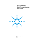
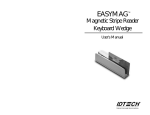
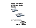
Sun™ StorEdge™ FC-100
Long Wave Gigabit Interface
Converter Guide
Caution – LW GBIC performance depends upon the correct
implementation of a 10 km Single Mode Optical Fiber Cable Plant which
complies with the specifications provided in Section A.3 “Single Mode
Cable Plant”.
A Sun sales representative must complete and submit a pre-sales
agreement which certifies that your installation meets the above
specifications before the sales order will be approved.
Sun Microsystems, Inc.
901 San Antonio Road
Palo Alto, CA 94303-4900 USA
650 960-1300
Fax 650 969-9131
Part No. 805-6965-10
September 1998, Revision A
Send comments about this document to: [email protected]
Copyright 1998 Sun Microsystems, Inc., 901 San Antonio Road • Palo Alto, CA 94303 USA. All rights reserved.
This product or document is protected by copyright and distributed under licenses restricting its use, copying, distribution, and
decompilation. No part of this product or document may be reproduced in any form by any means without prior written authorization
of Sun and its licensors, if any. Third-party software, including font technology, is copyrighted and licensed from Sun suppliers.
Parts of the product may be derived from Berkeley BSD systems, licensed from the University of California. UNIX is a registered trademark in
the U.S. and other countries, exclusively licensed through X/Open Company, Ltd.
Sun, Sun Microsystems, the Sun logo, Sun StorEdge, Sun Enterprise, docs.sun.com, AnswerBook, Java, the Java Coffee Cup logo, and Solaris are
trademarks, registered trademarks, or service marks of Sun Microsystems, Inc. in the U.S. and other countries. All SPARC trademarks are used
under license and are trademarks or registered trademarks of SPARC International, Inc. in the U.S. and other countries. Products bearing
SPARC trademarks are based upon an architecture developed by Sun Microsystems, Inc.
The OPEN LOOK and Sun™ Graphical User Interface was developed by Sun Microsystems, Inc. for its users and licensees. Sun acknowledges
the pioneering efforts of Xerox in researching and developing the concept of visual or graphical user interfaces for the computer industry. Sun
holds a non-exclusive license from Xerox to the Xerox Graphical User Interface, which license also covers Sun’s licensees who implement OPEN
LOOK GUIs and otherwise comply with Sun’s written license agreements.
RESTRICTED RIGHTS: Use, duplication, or disclosure by the U.S. Government is subject to restrictions of FAR 52.227-14(g)(2)(6/87) and
FAR 52.227-19(6/87), or DFAR 252.227-7015(b)(6/95) and DFAR 227.7202-3(a).
DOCUMENTATION IS PROVIDED “AS IS” AND ALL EXPRESS OR IMPLIED CONDITIONS, REPRESENTATIONS AND WARRANTIES,
INCLUDING ANY IMPLIED WARRANTY OF MERCHANTABILITY, FITNESS FOR A PARTICULAR PURPOSE OR NONINFRINGEMENT, ARE DISCLAIMED, EXCEPT TO THE EXTENT THAT SUCH DISCLAIMERS ARE HELD TO BE LEGALLY INVALID.
Copyright 1998 Sun Microsystems, Inc., 901 San Antonio Road • Palo Alto, CA 94303 Etats-Unis. Tous droits réservés.
Ce produit ou document est protégé par un copyright et distribué avec des licences qui en restreignent l’utilisation, la copie, la distribution, et la
décompilation. Aucune partie de ce produit ou document ne peut être reproduite sous aucune forme, par quelque moyen que ce soit, sans
l’autorisation préalable et écrite de Sun et de ses bailleurs de licence, s’il y en a. Le logiciel détenu par des tiers, et qui comprend la technologie
relative aux polices de caractères, est protégé par un copyright et licencié par des fournisseurs de Sun.
Des parties de ce produit pourront être dérivées des systèmes Berkeley BSD licenciés par l’Université de Californie. UNIX est une marque
déposée aux Etats-Unis et dans d’autres pays et licenciée exclusivement par X/Open Company, Ltd.
Sun, Sun Microsystems, le logo Sun, Sun StorEdge, Sun Enterprise, docs.sun.com, AnswerBook, Java, le logo Jave Coffee Cup, et Solaris sont des
marques de fabrique ou des marques déposées, ou marques de service, de Sun Microsystems, Inc. aux Etats-Unis et dans d’autres pays. Toutes
les marques SPARC sont utilisées sous licence et sont des marques de fabrique ou des marques déposées de SPARC International, Inc. aux EtatsUnis et dans d’autres pays. Les produits portant les marques SPARC sont basés sur une architecture développée par Sun Microsystems, Inc.
L’interface d’utilisation graphique OPEN LOOK et Sun™ a été développée par Sun Microsystems, Inc. pour ses utilisateurs et licenciés. Sun
reconnaît les efforts de pionniers de Xerox pour la recherche et le développement du concept des interfaces d’utilisation visuelle ou graphique
pour l’industrie de l’informatique. Sun détient une licence non exclusive de Xerox sur l’interface d’utilisation graphique Xerox, cette licence
couvrant également les licenciés de Sun qui mettent en place l’interface d’utilisation graphique OPEN LOOK et qui en outre se conforment aux
licences écrites de Sun.
CETTE PUBLICATION EST FOURNIE "EN L’ETAT" ET AUCUNE GARANTIE, EXPRESSE OU IMPLICITE, N’EST ACCORDEE, Y
COMPRIS DES GARANTIES CONCERNANT LA VALEUR MARCHANDE, L’APTITUDE DE LA PUBLICATION A REPONDRE A UNE
UTILISATION PARTICULIERE, OU LE FAIT QU’ELLE NE SOIT PAS CONTREFAISANTE DE PRODUIT DE TIERS. CE DENI DE
GARANTIE NE S’APPLIQUERAIT PAS, DANS LA MESURE OU IL SERAIT TENU JURIDIQUEMENT NUL ET NON AVENU.
Please
Recycle
Contents
Preface
1.
v
LW GBIC Installation and Removal
1.1
Planning the Configuration
1.2
Installing the LW GBIC
1.3
Removing the LW GBIC
1.4
Maintaining Fiber Optic Cables
A. Specifications
A.1
A.2
A.3
1-1
1-1
1-4
1-6
1-7
A-1
LW GBIC
A-2
A.1.1
Laser Safety
A-2
A.1.2
Optical Characteristics
A.1.3
Mechanical Specifications
A.1.4
Center Wavelength Versus Spectral Width
A-3
A-4
Single Mode Cable With Duplex SC Connectors
A.2.1
Environmental and Safety Specifications
A.2.2
Optical and Mechanical Characteristics
A.2.3
Single Mode Optical Fiber Specifications
Single Mode Cable Plant
A-4
A-5
A-5
A-6
A-6
A-7
A.3.1
Connector Specification
A-7
A.3.2
Single Mode Optical Fiber Specifications
A-7
Contents
iii
iv
Sun StorEdge FC-100 Long Wave Gigabit Interface Converter Guide • September 1998
Preface
The Sun StorEdge FC-100 Long Wave Gigabit Interface Converter Guide explains how to
install Sun™ StorEdge™ FC-100 Long Wave Gigabit Interface Converters
(LW GBICs) into Sun disk arrays and hubs.
Using UNIX Commands
This document does not contain information on basic UNIX® commands and
procedures such as shutting down the system, booting the system, and configuring
devices.
See one or more of the following for this information:
■
Solaris Handbook for Sun Peripherals
■
AnswerBook™ online documentation for the Solaris™ software environment
■
Other software documentation that you received with your system
v
Typographic Conventions
TABLE P-1
Typographic Conventions
Typeface
Meaning
Examples
AaBbCc123
The names of commands, files,
and directories; on-screen
computer output
Edit your .login file.
Use ls -a to list all files.
% You have mail.
AaBbCc123
What you type, when
contrasted with on-screen
computer output
% su
Password:
AaBbCc123
Book titles, new words or
terms, words to be emphasized
Read Chapter 6 in the User’s Guide.
These are called class options.
You must be superuser to do this.
Command-line variable;
replace with a real name or
value
To delete a file, type rm filename.
Shell Prompts
TABLE P-2
vi
Shell Prompts
Shell
Prompt
C shell
machine_name%
C shell superuser
machine_name#
Bourne shell and Korn shell
$
Bourne shell and Korn shell superuser
#
Sun StorEdge FC-100 Long Wave Gigabit Interface Converter Guide • September 1998
Related Documentation
See the Sun StorEdge A5000 Installation Tasks and Documentation Guide, part number
805-1903-xx, for the list of related documentation.
Sun Documentation on the Web
The docs.sun.comsm web site enables you to access Sun technical documentation
on the Web. You can browse the docs.sun.com archive or search for a specific book
title or subject at:
http://docs.sun.com
Sun Welcomes Your Comments
We are interested in improving our documentation and welcome your comments
and suggestions. You can email your comments to us at:
[email protected]
Please include the part number of your document in the subject line of your email.
vii
viii
Sun StorEdge FC-100 Long Wave Gigabit Interface Converter Guide • September 1998
CHAPTER
1
LW GBIC Installation and Removal
This chapter explains how to plan LW GBIC configurations and how to install and
remove LW GBICs.
1.1
Planning the Configuration
This section shows the supported LW GBIC cabling guidelines in Sun StorEdge
device configurations.
FIGURE 1-1 and FIGURE 1-2 show the supported configurations between initiators and
the Sun StorEdge A5000 Disk Array and StorEdge FC-100 Hubs. Use these
illustrations in conjunction with the information in the Sun StorEdge A5000 Disk
Array Hardware Configuration Guide, part number 805-0264-xx, to plan your
configuration.
The LW GBIC can be inserted into host adapter cards or Sun™ Enterprise™ SBus+
I/O Boards.
Note – LW GBICs must be connected in pairs.
Additional configurations may become available in the future. For an updated list of
supported configurations, go to the “Storage & Peripherals” section of the
docs.sun.com web site and read the Sun StorEdge A5000 Installation Supplement:
http://docs.sun.com
1-1
Remote host
LW1 LW2 LW3
1-2
LW4
LW5
LW6
LW7
FIGURE 1-1
LW GBIC Configuration Between Initiators and a Single Disk Array
TABLE 1-1
Index to FIGURE 1-1
Number
Component
LW1
LW GBIC
LW2
15m single-mode fiber optic cable
LW3
Wall or socket connection
LW4
Up to 10K single-mode fiber optic cable
LW5
Wall or socket connection
LW6
15m single-mode fiber optic cable
LW7
LW GBIC
Sun StorEdge FC-100 Long Wave Gigabit Interface Converter Guide • September 1998
1 2 3 4 5 6 7
LW1
LW2 LW3
LW4
LW5 LW6
LW7
Remote host
Local host
SW1
SW2
SW3
FIGURE 1-2
LW GBIC Configuration Between Initiators and StorEdge FC-100 Hub
TABLE 1-2
Index to FIGURE 1-2
Number
Component
LW1
LW GBIC
LW2
15m single-mode fiber optic cable
LW3
Wall or socket connection
LW4
Up to 10K single-mode fiber optic cable
LW5
Wall or socket connection
LW6
15m single-mode fiber optic cable
LW7
LW GBIC
SW1
SW GBIC1
SW2
Fiber optic cable
SW3
SW GBIC
1. SW GBIC refers to the multi mode 500m default GBIC used in Sun StorEdge A5000 Disk
Array factory configurations.
Chapter 1
LW GBIC Installation and Removal
1-3
1.2
Installing the LW GBIC
Caution – Forcing a LW GBIC into a port can damage the LW GBIC and/or the
port. Use minimal pressure when inserting the LW GBIC.
1. Unwrap the LW GBIC and pull out the dust covers.
2. With the bail in the unlock position, insert the LW GBIC into the port. The unlock
position is with the bail near the top of the LW GBIC (FIGURE 1-3).
LW GBICs are keyed to prevent improper insertion; they can be installed only as
shown below.
Top
Bail
Key
Blue connector
FIGURE 1-3
1-4
Installing the LW GBIC
Sun StorEdge FC-100 Long Wave Gigabit Interface Converter Guide • September 1998
3. Move the bail down into the locked position (FIGURE 1-4).
FIGURE 1-4
Moving the Tab Into the Locked Position
4. Pull lightly on the bail to ensure that it is properly locked into place.
5. Connect a fiber optic cable to the LW GBIC (FIGURE 1-5).
Fiber optic cables are keyed to prevent improper insertion; they can be installed only
as shown below.
Notches
Tabs
(not visible)
FIGURE 1-5
Connecting the Fiber Optic Cable
Chapter 1
LW GBIC Installation and Removal
1-5
1.3
Removing the LW GBIC
1. Disconnect the fiber optic cable connector from the LW GBIC.
Caution – You must remove the fiber optic cable from the LW GBIC before
removing the LW GBIC.
2. Move the bail to the unlocked position (FIGURE 1-6).
Plastic
tab
FIGURE 1-6
Moving the Bail to the Unlocked Position
3. Pull on the bail’s plastic tab to remove the LW GBIC.
1-6
Sun StorEdge FC-100 Long Wave Gigabit Interface Converter Guide • September 1998
1.4
Maintaining Fiber Optic Cables
Caution – Follow these guidelines to avoid causing damage to fiber optic cables.
The minimum bend radius for fiber optic cables is 1.2 inches (3 cm).
Make sure to grasp the connector when disconnecting a fiber optic cable. Never
disconnect a fiber optic cable by pulling on the cable.
To avoid damage due to contamination or abrasion, always put dust covers on the
fiber optic cable connectors when the cable is disconnected.
Dirty fiber optic cable connectors can impeded data transfer.
Before replacing a fiber optic cable, make sure that the connectors on the cable and
LW GBIC are clean.
1. Disconnect the fiber optic cable.
2. Lightly dip a cotton swab in a solution of pharmaceutical-grade isopropyl alcohol.
3. Use the swab and clean the inside of both connectors, as well as the insides of the
LW GBICs and other connectors.
4. Reconnect the connectors.
If the fiber optic cable still registers as being faulty, replace the fiber optic cable.
Chapter 1
LW GBIC Installation and Removal
1-7
1-8
Sun StorEdge FC-100 Long Wave Gigabit Interface Converter Guide • September 1998
APPENDIX
A
Specifications
This appendix contains specifications for the following components:
■
LW GBIC—page A-2
■
Single Mode Cable With Duplex SC Connectors—page A-5
■
Single Mode Cable Plant—page A-7
A-1
A.1
LW GBIC
This section contains specifications for the LW GBIC. The LW GBIC meets or exceeds
the Fibre Channel Standard 100-SM-LC-L specification.
A.1.1
Laser Safety
The LW GBIC is Class I Laser safe under single fault conditions for the when used
with Sun-approved power sources at the operating temperatures specified in
Section A.1.2 “Optical Characteristics” on page A-3.
TABLE A-1
Laser Safety Standards
Parameter
References
International Standards
IEC825-1 and IEC 825-2
FDA Standard
CDRH 21 CFR Ch1. Sub J Part 1040.10
Class 1 Laser Product
Luokan 1 Laserlaite
Klasse 1 Laser Apparat
Laser Klasse 1
FIGURE A-1
A-2
Laser Compliance Label
Sun StorEdge FC-100 Long Wave Gigabit Interface Converter Guide • September 1998
A.1.2
Optical Characteristics
TABLE A-2
Link
Parameter
Min
Nominal bit rate (B)
1062.5±200 PPM Mb/s
Operating range (L)
2m
Loss budget
10.5 dB
Typical fiber core diameter (MFD)
8.5
9.8
Parameter
Min
Max
Spectral center frequency (l)
1285 nm RMS
1345 nm RMS
Spectral width (∆l)
0.5 nm RMS
3 nm RMS
Launched power (P)
-8 dBm
-3 dBm
TABLE A-3
Max
10 Km
Transmitter
Relative intensity noise (RIN)
-120 dB/Hz
Extinction ratio (Ex)
9 dB
0.20 UI1 (pk-pk)
Deterministic jitter (DJ)
Total jitter (TJ)
0.43 UI (pk-pk))
Optical rise and fall time
2
320 ps
1. 1 UI=941 pico-seconds
2. The optical rise and fall time is 20%-80% unfiltered. If a 4th order Bessel Thompson filter is used, the
unfiltered rise and fall time would be:
TRise/Fall = √ ((Trise/fall measured)2 - (Trise/fall filter)2)
TABLE A-4
Receiver
Parameter
Min
Max
Received power
-20 dBm
-3 dBm
Operating wavelength
1270 nm
1350 nm
Optical power penalty
4.2 dB
Return loss of receiver (RL)
12 dB
1
OE deterministic jitter added (DJ)
OE total jitter added (TJ)
1
0.17 UI (pk-pk)
0.15 UI (pk-pk)
1. Amount of jitter added by the converter only.
Appendix A
Specifications
A-3
A.1.3
Mechanical Specifications
TABLE 1-3
Mechanical Specifications
Parameter
Specification
Optical Connector Insertion
250 times1
LW GBIC Insertion
100 times2
1. The number of times SC Duplex connector can be inserted/removed into the LW GBIC.
2. The number of times a LW GBIC unit can be inserted/removed in to the mating assembly.
Center Wavelength Versus Spectral Width
Spectral Width Max (nm)
A.1.4
Sun Specifications
Center Wavelength (µm)
FIGURE A-2
Wavelength Versus Spectral Width
FC = FC Specification for 9.5 dB Power Budget
A-4
Sun StorEdge FC-100 Long Wave Gigabit Interface Converter Guide • September 1998
A.2
Single Mode Cable With Duplex SC
Connectors
Cable assemblies comply with the EIA/TIA 492BAAA specification. The cable color
is be yellow, and the connectors are be blue in compliance with Fibre Channel
adapted color coding.
A.2.1
Environmental and Safety Specifications
TABLE A-5
Environmental and Safety Specifications
Parameter
Min
Max
Storage temperature (at 5% to 95% RH)
-40 ˚ C
80 ˚ C
Operating temperature (at 10% to 90% RH)
-10 ˚ C
70 ˚ C
Flame retardance (OFNR)
1
Cable material minimum rating (UL-94)
1666
V-1
1. UL specification for cable flame retardation.
Appendix A
Specifications
A-5
A.2.2
Optical and Mechanical Characteristics
TABLE A-6
Optical and Mechanical Characteristics
Parameter
Min
1
Mean optical connector loss
Optical connector loss + 3s
0.25 dB
1
0.5 dB
Connector optical return loss (RL)2
Fiber tensile proof test
Cable bend radius
-30 dB
100 Kpsi
3
30 mm
Ferrule end radius
10 mm
Connector apex offset
25 mm
50 mm
4
Connector axial retention
90 N
Insertion/withdrawal force
Off axial rotational pull
Max
4
80 N
20 N
Cable/connector pull strength
90 N
Mating durability/insertion
500
.1 Verified with OFSTP-7 method.
2. Verified with FOTP-107 method.
3. Excess loss is less than 0.5 dB if the fiber is wrapped around a 30-mm radius Mandrel once.
4. Maximum optical loss variation is less than 0.5 dB.
A.2.3
Single Mode Optical Fiber Specifications
TABLE A-7
Single Mode Optical Fiber Specifications
Parameter
Min
Fiber attenuation at 1310
nm1
0.4 dB/Km
1
0.05 dB/Km
Excess attenuation
Zero dispersion wavelength (λ0)
1301.5 dB/Km
Zero dispersion slope (S0)
1. For a temperature range of -10˚ C to 85˚ C and 4% to 98% RH.
A-6
Max
Sun StorEdge FC-100 Long Wave Gigabit Interface Converter Guide • September 1998
1321 dB/Km
0.092 ps/(nm2•Km)
A.3
Single Mode Cable Plant
All cable plants must meet or exceed the requirements of EIA/TIA 492BAAA and
use approved single mode optical fibers such as Corning SMF-28 or Lucent
equivalent.
A.3.1
Connector Specification
TABLE A-8
Connector Specification
Parameter
Max
Mean optical connector loss1
Optical connector loss + 3s
0.25 dB
1
0.5 dB
2
Connector optical return loss (RL)
-30 dB
1. Verified with OFSTP-7 method.
2. Verified with FOTP-107 method.
A.3.2
Single Mode Optical Fiber Specifications
TABLE A-9
Single Mode Optical Fiber Specifications
Parameter
Min
Max
Mode field diameter (MFD)
8.8 µm
9.8 µm
Cladding diameter
124 µm
126 µm
Cladding non-circularity
1%
Cable cutoff wavelength
Fiber attenuation at 1310 nm
1260 nm
1
0.4 dB/Km
1
0.05 dB/Km
Excess attenuation
Zero dispersion wavelength (λ0)
1301.5 dB/Km
Zero dispersion slope (S0)
1321.5 dB/Km
0.092 ps/(nm2•Km)
1. For temperature range of -10˚ C to 85˚ C and 4% to 98% RH.
Appendix A
Specifications
A-7
A-8
Sun StorEdge FC-100 Long Wave Gigabit Interface Converter Guide • September 1998