1
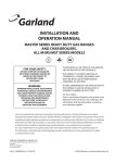
INSTALLATION AND OPERATING
INSTRUCTIONS
FOR THE SUNFIRE
X SERIES GAS RESTAURANT RANGES
FOR YOUR SAFETY
DO NOT STORE OR USE GASOLINE OR OTHER
FLAMMABLE VAPORS OR LIQUIDS IN THE
VICINITY OF THIS OR ANY OTHER APPLIANCE.
WARNING:
IMPROPER INSTALLATION, ADJUSTMENT,
ALTERATION, SERVICE OR MAINTENANCE CAN
CAUSE PROPERTY DAMAGE, INJURY OR DEATH.
READ THE INSTALLATION, OPERATION AND
MAINTENANCE INSTRUCTIONS THOROUGHLY
BEFORE INSTALLING OR SERVICING
THIS EQUIPMENT.
PLEASE READ ALL SECTIONS OF THIS MANUAL AND RETAIN FOR FUTURE REFERENCE.
THIS PRODUCT HAS BEEN CERTIFIED AS COMMERCIAL COOKING EQUIPMENT AND MUST BE INSTALLED
BY PROFESSIONAL PERSONNEL AS SPECIFIED.
For Your Safety:
Post in a prominent location, instructions to be followed in the event the user smells gas. This information shall be
obtained by consulting your local gas supplier.
Users are cautioned that maintenance and repairs must be performed by a Garland authorized service agent using genuine
Garland replacement parts. Garland will have no obligation with respect to any product that has been improperly installed,
adjusted, operated or not maintained in accordance with national and local codes or installation instructions provided
with the product, or any product that has its serial number defaced, obliterated or removed, or which has been modified
or repaired using unauthorized parts or by unauthorized service agents. For a list of authorized service agents, please refer
to the Garland web site at http://www.garland-group.com. The information contained herein, (including design and parts
specifications), may be superseded and is subject to change without notice.
Continuous product improvement is a Garland policy, therefore design and specifications are subject to change without notice.
GARLAND COMMERCIAL INDUSTRIES
185 East South Street
Freeland, Pennsylvania 18224
Phone: (570) 636-1000
Fax: (570) 636-3903
Part
Part##XXXXXXX
XXXXXXX(02/07)
(02/07)
GARLAND COMMERCIAL RANGES,
LTD.
1177 Kamato Road, Mississauga, Ontario L4W 1X4
CANADA
Phone: 905-624-0260
Fax: 905-624-5669
Enodis UK LTD.
Swallowfield Way, Hayes, Middlesex UB3 1DQ ENGLAND
Telephone: 081-561-0433
Fax: 081-848-0041
© 2007 Garland Commercial Industries,Page
Inc.
IMPORTANT INFORMATION
WARNING:
This product contains chemicals known to the State of California to cause cancer and/or birth defects or other
reproductive harm. Installation and servicing of this product could expose you to airborne particles of glass wool/
ceramic fibers. Inhalation of airborne particles of glass wool/ceramic fibers is known to the State of California to
causes cancer. Operation of this product could expose you to carbon monoxide if not adjusted properly. Inhalation
of carbon monoxide is known to the State of California to cause birth defects or other reproductive harm.
Keep appliance area free and clear from combustibles
Page Part # XXXXXXX (02/07)
TABLE OF CONTENTS
Important Information . . . . . . . . . . . . . . . . 2
Operation . . . . . . . . . . . . . . . . . . . . . . . . . . 9
Dimensions And Specifications . . . . . . . . . . 4
Open Top burners . . . . . . . . . . . . . . . . . . . . . . . . 9
Gas Pressures . . . . . . . . . . . . . . . . . . . . . . . . . . . . 4
Individual Burner Input Rates . . . . . . . . . . . . . . . 4
Base Model Designations & Total Input Rates. . . 4
Clearances . . . . . . . . . . . . . . . . . . . . . . . . . . . . . . 4
Introduction . . . . . . . . . . . . . . . . . . . . . . . . 5
Rating Plate . . . . . . . . . . . . . . . . . . . . . . . . . . . . . 5
Installation . . . . . . . . . . . . . . . . . . . . . . . . . 5
Siting . . . . . . . . . . . . . . . . . . . . . . . . . . . . . . . . . . 5
Appliances Equipped With Casters. . . . . . . . . . . . 5
Appliances Equipped With Legs. . . . . . . . . . . . . . 6
Installing Shelf To Backguard. . . . . . . . . . . . . . . . 6
Backguard With High Shelves, Salamander
Or Cheesemelters Mounting Instructions. . . . . . . 6
Ventilation Air. . . . . . . . . . . . . . . . . . . . . . . . . . . 6
Statutory Regulations. . . . . . . . . . . . . . . . . . . . . . 7
Ovens (Standard). . . . . . . . . . . . . . . . . . . . . . . . . 9
“RC” Convection Ovens. . . . . . . . . . . . . . . . . . . . 9
Hot Top Sections. . . . . . . . . . . . . . . . . . . . . . . . 10
Valve Controlled Griddles. . . . . . . . . . . . . . . . . . 10
Range Shut down. . . . . . . . . . . . . . . . . . . . . . . . 10
Product Application Information . . . . . . . 11
General. . . . . . . . . . . . . . . . . . . . . . . . . . . . . . . . 11
Open Burners. . . . . . . . . . . . . . . . . . . . . . . . . . . 11
Maintenance And Cleaning . . . . . . . . . . . 12
Seasoning. . . . . . . . . . . . . . . . . . . . . . . . . . . . . . 12
Griddle . . . . . . . . . . . . . . . . . . . . . . . . . . . . 12
Cast Iron top Grates . . . . . . . . . . . . . . . . . . 12
Stainless Steel. . . . . . . . . . . . . . . . . . . . . . . . . . . 12
Oven Interior (Porcelain Enamel)
Convection Oven Base. . . . . . . . . . . . . . . . . . . . 13
Gas Connection. . . . . . . . . . . . . . . . . . . . . . . . . . 7
Interior Cleaning of Standard
Aluminized Steel Interior Surfaces . . . . . . . . . . . 13
Electrical Connections (Where Applicable). . . . . . 7
Open Top Burners . . . . . . . . . . . . . . . . . . . . . . . 13
Installation Notes. . . . . . . . . . . . . . . . . . . . . . . . . 7
Cast Iron Top & Ring Grates. . . . . . . . . . . . . . . 13
Testing And Adjustment . . . . . . . . . . . . . . . 8
Hot Tops . . . . . . . . . . . . . . . . . . . . . . . . . . . . . . 14
Testing. . . . . . . . . . . . . . . . . . . . . . . . . . . . . . . . . 8
Griddle. . . . . . . . . . . . . . . . . . . . . . . . . . . . . . . . 14
Part # XXXXXXX (02/07)
Page DIMENSIONS AND SPECIFICATIONS
Gas Pressures
Gas
Minimum Supply
Pressure
Manifold Operating
Pressure
Natural
7” WC (17.5 mbar)
4.5” WC (11.25 mbar)
Propane
11” WC (28 mbar)
10” WC (25 mbar)
Individual Burner Input Rates
Input BTU/HR
Burner
Natural
Gas
Propane
Gas
Open Top
30,000
30,000
Hot Top Burner (In lieu of 2 open top burners)
20,000
19,000
Griddle Burner (In lieu of 2 open top burners)
20,000
19,000
Oven Burner Standard or Convection
33.000
30,000
Base Model Designations & Total Input Rates
Model #
Input BTU/Hr
Description
Natural Gas
Propane Gas
X36-6S
36” (914mm) unit, 6 open burners, storage base
180,000
180,000
X36-6R
36” (914mm) unit, 6 open burners, standard oven
213,000
213,000
X36-6C
36” (914mm) unit, 6 open burners, convection oven
213,000
213,000
X60-10SS
60” (1524mm) unit, 10 open burners, storage base
300,000
300,000
X60-10RS
60” (1524mm) unit, 10 open burners, standard oven
333,000
333.000
X60-10CS
60” (1524mm) unit, 10 open burners, convection oven
333,000
333,000
X60-10CR
60” (1524mm) unit, 10 open burners, standard oven, convection oven
366,000
366,000
X60-10RR
60” (1524mm) unit, 10 open burners, 2 standard ovens
366,000
366,000
X60-10CC
60” (1524mm) unit, 10 open burners, 2 convection ovens
366,000
366,000
Clearances
Clearances Applicable For All Models
Page Surface
Sides
Rear
Combustible Wall Minimum
12” (305mm)
6” (152mm)
Non-Combustible Wall Minimum
0”
0”
Part # XXXXXXX (02/07)
INTRODUCTION
1. Check crate for possible damage sustained during
transit. Carefully remove unit from crate and again
check for damage. Any damage to the appliance
must be reported to the carrier immediately.
4. The type of gas and supply pressure that the
equipment was set-up for at the factory is noted on
the rating plate and on the packaging. This type of
gas supply must be used.
2. The wires for retaining packing material must
be removed from units. Any protective material
covering stainless steel parts must also be removed.
5. Do not remove permanently affixed labels, warnings
or rating plates from the appliance, for this may
invalidate the manufacturer’s warranty
3. All equipment is shipped from the factory with legs
fitted, unless otherwise specified. Where the range
is to be mounted on a dais or cove base, it is shipped
without legs. Legs must be fitted to the oven when
it is installed on a combustible floor.
Rating Plate
All burner input rates are shown on the rating plate,
which is located behind the lower front drop down panel
under the oven door.
INSTALLATION
This product has been certified as commercial cooking
equipment and must be installed by professional
personal as specified. THIS APPLIANCE IS
NOT RECOMMENDED FOR RESIDENTIAL
INSTALLATION.
We suggest installation, maintenance and repairs
should be preformed by your local Garland/US Range
authorized service agency.
Siting
The floor on which the appliance is to be sited must
be capable of adequately supporting the weight of the
appliance and any ancillary equipment. Units with ovens
must be fitted with legs if installed on a combustible
floor. Adequate clearance must be provided for servicing
and proper operation.
Part # XXXXXXX (02/07)
Appliances Equipped With Casters
1. The installation shall be made with a connector
that complies with the Standard for Connectors for
Moveable Gas Appliances, ANSI Z21.69, (or latest
edition), addenda Z21.69a-1989, or Connectors
for Moveable Gas Appliances, CAN/CGA-6-16 or
latest edition, and a quick-disconnect device that
complies with the Standard for Quick Disconnects
for Use with Gas Fuel, ANSI Z21.41 or latest
edition, or Quick Disconnect Devices for Use with
Gas Fuel, CAN1-6.9 or latest edition.
2. The front casters of the appliance are equipped
with brakes to limit the movement of the appliance
without placing any strain on the connector or
quick disconnect device or its associated piping.
3. Please be aware; required restraint is attached to a
bracket, (which is located on the rear of the caster
closest to the gas connection), and if disconnection
of the restraint is necessary, be sure to reconnect the
device after the appliance has been returned to its
original position.
Page INSTALLATION Continued
Appliances Equipped With Legs
1. Raise the front of the appliance and block. Do not
lay the appliance on its back.
2. Legs are threaded to be easily threaded into the
holes provided on the bottom of the range.
3. Once legs have been attached and secured they can
be adjusted up level the appliance to compensate for
uneven flooring.
Installing Shelf To Backguard
Backguard With High Shelves, Salamander
Or Cheesemelters Mounting Instructions
1. Rear of the range must be easily accessible
2. Place the backguard, high shelf, salamander, or
cheesmelter on the rear of the range, slipping the
support brackets into the openings in the burner
box sides.
3. Securely fasten the support brackets to the burner
box sides with (4) #14 x 5/8” Hex washer head, type
B tapping screws. (Hardware package is supplied).
Note: Shelf may be installed before or after installing
the backguard to the range.
Upright
1. Loosen 4 bolts on the front of the backguard
approximately 1/4” (6mm).
2. Align the 4 holes on the back of the shelf with the
4 bolts on the backguard.
Burner Box
Side
3. Slide the shelf downward until the 4 bolts are
engaged in the slotted portion of the keyhole.
1/4" x 3/4"
Type "B"
Washer Hex
Head SMS
4 Req'd
4. Tighten the 4 bolts to secure shelf.
5. On 60” units only, install a sheet metal screw
though the hole in the underside of the shelf into
the backguard and tighten.
Ventilation Air
MOUNTING
BOLTS
SHELF
SHEETMETAL
SCREW
BACKGUARD
The following notes are intended to give general guidance.
For detailed recommendations, refer to the applicable
code(s) in the country of destination.
Proper ventilation is highly essential for optimum
performance. The ideal method of ventilating open-top
equipment is the use of a properly designed canopy that
should extend six inches (152 mm), beyond all sides of
the appliance(s) and six feet, six inches (1981mm) above
the floor.
A strong exhaust will create a vacuum in the room. For
an exhaust vent to work properly, replacement air must
equal to the amount exhausted.
Page Part # XXXXXXX (02/07)
INSTALLATION Continued
All gas burners and pilots need sufficient air to operate.
Large objects should not be placed in front of the
appliance(s) that would obstruct the flow of air into
the front
Statutory Regulations
The installation of this appliance must be carried out by
a competent person and in accordance with the relevant
regulations, codes of practice and the related publications
of the country and destination.
The installation must conform to the National Fuel Gas
Code ANSI Z223.1, or latest edition, NFRA No.54
- latest edition/or local code to assure safe and efficient
operation. In Canada, the installation must comply with
CSA B149.1 and local codes.
Gas Connection
The local gas authority should be consulted at the
installation planning stage in order to establish the
availability of an adequate supply of gas and to ensure
that the meter is adequate for the required flow rate. The
pipe work from the meter to the appliances must be of
an appropriate size.
All fixed (non-mobile) appliances MUST be fitted with
a manual gas-cock upstream of the appliance to provide
a means of isolation for servicing or cleaning purposes.
A union or similar means of disconnection must be
provided between the gas-cock and the appliance.
A manually operable valve must be fitted to the gas
supply to the kitchen to enable it to be isolated in an
emergency. Wherever practical, this shall be located
either outside the kitchen or near to an exit in a readily
accessible position.
Where it is not practical to do this, an automatic isolation
valve system shall be fitted which can be operated from
a readily accessible position near to the exit.
At locations where the manual isolation valve is fitted
or the automatic system can be reset a notice MUST
be posted stating:
“ALL DOWNSTREAM BURNER AND PILOT
VALVES MUST BE TURNED OFF PRIOR TO
ATTEMPTING TO RESTORE THE SUPPLY.
AFTER EXTENDED SHUT OFF, PURGE BEFORE
RESTORING GAS.”
Electrical Connections (Where Applicable)
IMPORTANT- This appliance must be electrically
grounded in accordance with local codes, with the
National Electrical Code.
220/240 Volt Convection Oven Models
When the appliance is ordered and equipped for 220/240
volt operation, the supply line must be connected to the
wiring terminations located inside the terminal box at
the rear of the appliance.
For ease of attaching the supply line, there is a removable
cover on the terminal box.
Permanent connection to the electrical service must
comply with local codes, or in the absence of local codes,
with the national electrical code.
Installation Notes
Before assembly and connection check gas supply.
A. The type of gas for which the unit is equipped is
stamped on the data plate located behind the lower
front panel. Connect a unit stamped “NAT” only
to natural gas; connect one stamped “PRO” only to
propane gas.
B. If it is a new installation have the gas authorities
check meter size and piping to assure that the unit
is supplied with necessary amount of gas pressure
required to operate the unit.
C. If it is additional or replacement equipment have the
gas authorities check pressure to make certain that
existing meter and piping will supply fuel to the
unit with no more than 0.15 Kpa pressure drop.
Part # XXXXXXX (02/07)
Page INSTALLATION Continued
D. Make certain new piping and connections have
been made in a clean manner and have been purged
so that piping compound, chips, etc. will not clog
pilots, valves or burners. Use pipe joint compound
approved for natural and liquefied petroleum
gases.
NOTE: Gas pressure should be checked when the unit
is installed and all other equipment on the same line
is on. The operating gas pressure must be the same as
that specified on the rating plate. If necessary, pressure
adjustment may be made at the pressure regulator
supplied with the appliance.
The appliance and its individual shut-off valve must be
disconnected from the gas supply piping system during
any pressure testing of that system pressures in excess
of 1/2 PSIG (3.45kPa.)
TESTING AND ADJUSTMENT
Testing
4. Light the oven pilot.
All fittings and pipe connections must be tested for
leaks. Use approved gas leak detectors, soap solution
or equivalent, checking over and around all the fittings
and pipe connections. DO NOT USE A FLAME!
Accessibility to all gas lines and fittings require that
valve panel(s) lower front panel(s), and/or oven rack(s)
be removed. It may be necessary to remove, or at least
raise and securely prop griddle(s), hot top(s), and/or top
grate(s). All parts removed, (including fasteners), should
be stored safely for re-installation.
5. In either case, now set the oven thermostat to
maximum. Leak test all valves and fittings as
described at the beginning of this section. Correct
any leaks as required and recheck.
1. Be sure that all valves and thermostats are in the
“OFF” position.
2. Turn on the main gas supply valve. Light all top
section pilots.
3. Leak test all valves and fittings as described at the
beginning of this section. Correct any leaks as
required and recheck.
Page 6. Shut off all valves and set thermostat dials to
“OFF” or lowest position. All units are tested and
adjusted at the factory, however, burners and pilots
should be checked upon installation and adjusted if
necessary.
CAUTION: Gas will flow to the top section burners
even if top section pilots are not lit. Gas will not be
interrupted. It is the responsibility of the operator
to confirm the proper ignition of each burner as it
is turned on. Should ignition fail to occur 5 seconds
after turning a burner on, turn the burner off, wait 5
minutes, and try again.
Part # XXXXXXX (02/07)
OPERATION
Open Top burners
Lighting:
1. Light pilots are adjacent to each burner.
2. Turn valve completely on. Burner flame should be
1/2-inch, (13mm), stable blue flame, and should
impinge on the bottom of a pot placed on the ring
great.
CAUTION: Should burner ignition fail within 4
seconds, turn the burner valve off and repeat steps 1
through 2. If ignition continues to fail, consult your
factory authorized service agency.
CAUTION: Gas will flow to the top section burners
even if top section pilots are not lit. Gas will not be
interrupted. It is the responsibility of the operator
to confirm the proper ignition of each burner as it
is turned on. Should ignition fail to occur 5 seconds
after turning a burner on, turn the burner off, wait 5
minutes, and try again.
Ovens (Standard)
Lighting
1. Push in the valve knob, and turn it counterclockwise to the ignition position.
2. While holding the valve knob fully in, press the
ignitor button and observe that the pilot lights. If
it does not, repeatedly depress the ignition button
until it does.
3. When the pilot is lit, continue to hold the valve
knob fully in for 10 seconds, then release it. If the
pilot goes out, wait for five (5), minutes, then repeat
step 1.
6. To shut the burner and pilot completely off turn the
dial to the off symbol position. The safety device
will disengage within 60 seconds.
Convection Ovens
The forced air range oven consists of a food preparation
chamber completely sealed from the combustion area.
This eliminates the possibility of contamination from flue
products and permits an efficient method of circulating
the heated air within the cooking chamber.
During the cooking process in a conventional oven, a
vapor barrier and a layer of “cool” air covers the exposed
area of the product. In a forced air oven, the fan pushes
the heated air over and around the product, sweeping
away the vapor barrier and cool air, permitting faster
heat penetration. This action permits the use of lower
temperatures and shorter cooking times.
The rule of thumb for determining the cooking
temperature is to reduce the set temperature by
approximately 80°F, (28°C), from that which you
would set in a conventional oven, and that the product
be checked at a point midway in the time required in a
conventional oven.
Lighting
Refer to the section titled “OVENS (STANDARD)”
above for detailed instructions.
Start Up
1. Set the power switch to the “COOK” position.
2. Turn the oven valve knob to the “flame” symbol.
3. Turn the thermostat to the desired setting.
Cool down
4. When the pilot has been established, turn the knob
counter-clockwise to oven flame position, then set
the thermostat to the desired temperature.
1. Turn the oven valve knob to the circular “OFF”.
5. To keep the main burner flame closed and but the
pilot flame lit turn the control knob to the pilot
position. Do not push into knob.
3. Open the oven door.
Part # XXXXXXX (02/07)
2. Turn the thermostat to its lower setting.
4. Set the power switch to the “COOL DOWN”
position.
Page OPERATION continued
Shut Down
Hot Top Sections
1. Turn the oven valve knob to the circular “OFF”
symbol.
1. Raise or remove hot top sections. Each burner
has one pilot located at the front right side of the
burner.
2. Turn the thermostat to its lowest setting.
3. Set the power switch to the “OFF” position.
Operating Suggestions
The motor on your range convection oven is maintenance
free since it is constructed with self-lubricating sealed ball
bearings. It is designed to proved durable service when
treated with ordinary care. We have a few suggestions
to follow on the care of your motor.
A. When the motor is operating, it cools itself internally
by air entering the rear of the motor case, provided
proper clearance has been allowed.
B. Since the blower wheel is in the oven cavity it is at
the same temperature as the oven. If the motor is
stopped while the oven is hot, the heat from the
blower wheel is conducted down the shaft and
into the armature of the motor. This action could
shorten motor life.
C. We recommend, at the end of the bake or roasting
period, when the oven will be idle for any period
of time or before shutting down completely, that
the doors be left open, and by use of the cool-down
position on the fan switch, the fan continues to run
for at least 20 minutes. The “FAN” should never be
turned “OFF” when the oven is “HOT”.
Page 10
2. Light pilots. The pilot burner should be adjusted to
provide for rapid ignition of the burner.
3. Turn the burner valve on. A sharp blue flame should
be approximately 1/4-inch, (6mm), high.
4. Replace hot top sections.
Valve Controlled Griddles
See griddle seasoning before use.
1. Raise griddle at front and securely block.
2. Light pilots located at the front right side of each
burner.
3. Turn burner valves completely on. Burners should
have 1/2-inch to 5/8-inch, (13mm to 16mm), stable
blue flame.
4. Lower griddle carefully into position.
Range Shut down
1. Turn all valves to the “OFF” position.
2. If the unit is to be shut down for an extended period
of time, close the in-line gas valve.
Part # XXXXXXX (02/07)
PRODUCT APPLICATION INFORMATION
General
The range is the workhorse of the kitchen because of its
versatility. Most frequently used in small applications,
such as cafes, schools, church kitchens, firehouses, and
small nursing homes where demands are less taxing. As
a general rule of thumb, one four to six burner range
with a hot top will be adequate for a restaurant seating
30 to 35.
The top of the range is designed for flexibility and the
preparation of numerous different types of products. It
may be equipped with two, or even three different types
of tops and burners, depending on the menu needs. An
operation that cooks to order, or uses the range primarily
as back-up will find that open burners will suit most of
their needs.
Preparation of soups, stocks, or sauces is done on a hot
top where slow, even cooking in desirable.
Heating larger quantities of food can be done more
efficiently than heating small quantities. Pots and pans
should be covered whenever possible to reduce energy
consumption.
Part # XXXXXXX (02/07)
High acid sauces, such as tomato should be cooked in
stainless steel rather than aluminum to avoid chemical
reaction. Light colored sauces such as Alfredo may be
discolored by the use of aluminum, especially if stirred
with a metal spoon or whip. Saltwater shellfish may
pit aluminum pots if they are frequently used for this
purpose.
NOTE: Many parts of the commercial range are raw
steel. Hot tops, griddles, springs, door hooks etc., can
react with the moisture forming rust. This occurrence
is normal and not considered a defect. Clean with a
stainless steel or fiber pad. A light coating of cooking
oil may be applied.
Open Burners
The mist traditional uses of open burners are sautéing,
pan frying, and small stock pot work. Short-term cooking
is the most efficient use for the open burner. Pans should
cover as much of the grate as possible to minimize heat
loss. The maximum stop pot size to be used on an open
burner is 11 inches, (279mm), diameter. Open burners
should be turned off when not in use to conserve energy.
Leaving a flame burning is of no advantage since the
heat is instantaneous.
Page 11
MAINTENANCE AND CLEANING
Seasoning
Griddle
A. Remove all factory applied protective material by
washing with hot water, mild detergent or soap
solution.
B. Apply a thin coat of cooking oil to the griddle
surface, about one ounce per square foot of griddle
surface. Spread over the entire griddle surface with
a cloth to create a thin film. Wipe off any excess oil
with a cloth.
C. Light all burners, set a lowest possible setting. Some
discoloration will occur when heat is applied to
steel.
D. Heat the griddle slowly for 15 to 20 minutes. Then
wipe away oil. Repeat the procedure 2 to 3 times
until the griddle has a slick, mirror like finish. Do
this until you have reached the desired cooking
temperature.
IMPORTANT: Do not attain high (on valve control)
during “break-in” period
NOTE: Steel griddle surface will tone (blue discoloration)
from heat. This toning will not diminish function or
operation is not a defect.
The griddle will not require reseasoning if it is used
properly. If the griddle is over heated and product begins
to stick to the surface it may be necessary to repeat the
seasoning process again. If the griddle is cleaned with
soap and water it will be necessary to reseason the griddle
surface.
Cast Iron top Grates
First, remove the cast iron top grates from the range.
Wash the cast iron top grates thoroughly with a mild soap
and warm water. Dry the cast-iron top grates thoroughly
with a clean cloth. Immediately after drying, season the
top grates lightly with a non-toxic oil, (Liquid vegetable
oil or Pam spray oil) WARNING; DO NOT SEASON
THE TOP GRATES WHILE ON THE RANGE TOP!
Page 12
Seasoning grates on the range top over an open flame
could cause a flash fire. After seasoning, replace the top
grates onto the range. Turn all the range top sections “ON
LOW”. Allow the top sections to burn in this manner for
at least 20 minutes before using pots or pans on the top
grates. SEASONING OF THE TOP GRATES WILL
BE REQUIRED WHENEVER THEY HAVE BEEN
CLEANED. FAILURE TO SEASON GRATES WILL
CAUSE RUSTING.
Stainless Steel
For routine cleaning just wash with a hot water and
detergent solution. Wash just a small area at a time or
the water will evaporate leaving the chemicals behind
causing streaking.
Rinse the washed area with a clean sponge dipped in a
sanitizing solution and wipe dry with a soft clean cloth
before it can dry.
Use a paste (of water and a mild scouring powder) if you
have to, but never rub against the grain. All stainless steel
has been polished in one direction. Rub with the polish
lines to preserve the original finish. Then thoroughly
rinse as before.
To prevent fingerprints there are several stainless steel
polishes on the market that leave an oily or waxy film. Do
not use on surfaces that will be in contact with food.
Stainless steel may discolor if overheated. These stains can
usually be removed by vigorous rubbing with a scouring
powder paste.
Use only stainless steel, wood or plastic tools if necessary
to scrape off heavy deposits of grease and oil. Do not
use ordinary steel scrapers or knives, as particles of the
iron may become imbedded and rust. STEEL WOOL
SHOULD NEVER BE USED.
Either a typical bleach solution or hot water can be used
to sanitize stainless steel
Part # XXXXXXX (02/07)
MAINTENANCE AND CLEANING Continued
Oven Interior (Porcelain Enamel)
Convection Oven Base
NOTE: Disconnect line cord (if applicable from power
supply before cleaning or servicing.
1. Before cleaning oven interior, remove all oven racks
and guides. Oven racks and guides can be cleaned
with a mild soap and warm water or run through
dish washer.
2. The porcelain interior can be cleaned with oven
cleaners such as “Easy Off, or “Dow Oven
Cleaner”.
Follow product manufacturer’s instructions for proper
use
Interior Cleaning of Standard Aluminized
Steel Interior Surfaces
The oven sides and top linings are formed of heavy
gauge steel with an aluminum fused into its surface to
provide for the reflectance of heat back to the food being
prepared and to virtually eliminate the possibility of rust
formation. Establish a regular cleaning schedule or wipe
off on the same day when spillovers occur.
1. Cool down oven.
2. Remove oven racks.
3. Lift rack guides on either side of oven off of holders,
pull the top away from the cavity wall, when it’s
cleared the clips push down and remove. Racks and
guides may be run through dishwasher while oven
cavity is being cleaned.
4. Use a concentrated detergent on a plastic pad to
remove burned on soil. Do Not Use Steel Wool,
Oven Cleaner Or Abrasive Powders. These will
remove the aluminum. Rinse with warm water on a
soft cloth. Be sure to remove all traces of detergent.
Any discoloration, which may remain after the
soil build-up has been removed, will not affect the
performance of the oven.
Part # XXXXXXX (02/07)
5. To reinstall reverse procedure. Place the bottom of
the rack guide against the cavity wall. Keeping the
top pulled away from the wall lift up. Push the top
of the rack guide against the wall and push down
locking it into place.
Open Top Burners
Cleaning of the range top burner is a simple procedure,
and, if done at regular intervals will prolong the life of
the range and ensure good flame characteristics.
1. The most common problem with open burner
ranges is spillage. Once the burner ports are
partially plugged with food, the air-to-gas mixture
is disturbed and results in an inefficient burner.
2. Wipe any spills as they occur.
3. Grids and trays should be removed daily, washed,
rinsed and dried thoroughly.
4. Use a wire brush to clean the ports of the burners.
Ignite and check for clogged holes.
5. If any clogged holes are apparent, the burner should
be lifted out and brushed inside and out with a
small venture brush. Each port on the burner itself
should be cleaned with a properly sized wire or
thumb drill. Wash with soap and hot water if grease
is observed on the burners. Dry thoroughly.
6. Reinstall and check the flame pattern. Readjust the
air shutter if necessary.
7. If a yellow flame appears around the edges instead
of being uniformly blue, it is usually a sign of grease
and dirt in the throat of the burner. Remove and
clean the burner and readjust the air shutter
Cast Iron Top & Ring Grates
Cast iron top and ring rate(s) can be cleaned with mild
soap and warm water. For baked on material, a wire
brush can be used. Dry thoroughly. Lightly coat with
vegetable oil to help prevent rust from forming.
Page 13
MAINTENANCE AND CLEANING Continued
Hot Tops
While the surface is still slightly warm, wipe down with
a clean burlap cloth. Burnt on spillage should be scraped
off. If necessary, remove the plate and wash in a sink with
soap and hot water. Dry thoroughly. In damp climates,
wipe down with a light coating of oil to prevent rusting.
Avoid excessive use of water at this could damage the
surface and the controls below.
NOTE: Steel griddle and hot top surface will “tone”
(blue/brown discoloration) from heat. This toning
will not diminish function or operation and is not a
defect.
Griddle
To produce evenly cooked, browned griddle products,
keep griddle free from carbonized grease. Carbonized
grease on the surface hinders the transfer of heat from the
griddle surface to food product. This results in uneven
browning and loss of cooking efficiency, and worst of
all, carbonized grease tends to cling to grilled foods,
giving them a highly unsatisfactory and unappetizing
appearance. To keep the griddle clean and operating at
peak performance, follow these simple instructions:
A. AFTER EACH USE clean griddle thoroughly with
a grill scraper or spatula. Wipe off any excess debris
left from cooking process.
Page 14
B. ONCE A DAY clean griddle surface with a grill
brick and grill pad. Remove grease container and
clean thoroughly, in same manner as any ordinary
cooking utensil.
C. ONCE A WEEK clean griddle surface thoroughly.
If necessary, use a grill stone or grill pad over the
griddle surface. Rub with grain of the metal while
still warm. A detergent may be used on the plate
surface to help clean it, but care must be taken to
be sure it is thoroughly removed. After removal of
detergent, the surface of the plate should be covered
with a thin film of oil to prevent rusting. To remove
discolorations, use a non-abrasive cleaner. Before
re-using, the griddle must be reseasoned. Keep
griddle drain tube to grease container clear at all
times on those models without grease container.
CAUTION This griddle plate is steel, but the surface
is relatively soft and can be scored or dented by careless
use of spatula.
Be careful not to dent, scratch, or gouge the plate surface.
This will cause food to stick in those areas. Also, note,
since this is a steel griddle if a light coating of oil is
not always present rust will develop on exposed and
uncoated areas.
Part # XXXXXXX (02/07)
NOTES
Part # XXXXXXX (02/07)
Page 15