1
■
■
I/O controller 0
I/O controller 1
When mapping the I/O device tree entry to a physical component in the server, you
must consider up to five nodes in the device tree:
■
■
■
■
■
Node identifier (ID)
I/O controller agent ID (AID)
Bus offset
PCI+ slot
Device instance
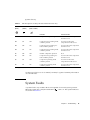
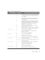
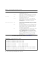
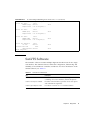
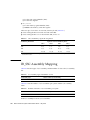
TABLE D-4 lists the AIDs for the two I/O controllers in each I/O assembly.
TABLE D-4
I/O Controller Agent ID Assignments
Slot Number
I/O Assembly Name
6
IB6
Even I/O controller AID
24
(18)*
Odd I/O Controller AID
25 (19)
* The first number in the column is a decimal number. The number (or a number and letter combination) in parentheses is
in hexadecimal notation.
The I/O controller has two bus sides – A and B.
■
■
Bus A, which is 66 MHz, is referenced by offset 600000.
Bus B, which is 33 MHz, is referenced by offset 700000.
The board slots located in the I/O assembly are referenced by the device number.
This section describes the PCI+ I/O assembly slot assignments and provides an
example of the device path.
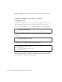
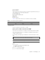
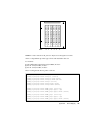
The following code example gives a breakdown of a device tree entry for a SCSI
disk:
/ssm@0,0/pci@19,700000/pci@3/SUNW,isptwo@4/sd@5,0
Note – The numbers in the device path are hexadecimal.
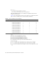
where:
■
in 19,700000
■
■
19 is the I/O controller agent identifier (AID).
700000 is the bus offset.
■
in pci@3, 3 is the device number.
■
isptwo is the SCSI host adapter.
Appendix D
Device Mapping
121