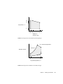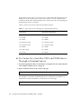
1
Sun Fire™ V210 and V240 Servers
Installation Guide
Sun Microsystems, Inc.
4150 Network Circle
Santa Clara, CA 95054 U.S.A.
650-960-1300
Part No. 816-4825-11
April 2003, Revision A
Send comments about this document to: [email protected]
Copyright 2002 Sun Microsystems, Inc., 4150 Network Circle, Santa Clara, California 95054, U.S.A. All rights reserved.
Sun Microsystems, Inc. has intellectual property rights relating to technology embodied in the product that is described in this document. In
particular, and without limitation, these intellectual property rights may include one or more of the U.S. patents listed at
http://www.sun.com/patents and one or more additional patents or pending patent applications in the U.S. and in other countries.
This document and the product to which it pertains are distributed under licenses restricting their use, copying, distribution, and
decompilation. No part of the product or of this document may be reproduced in any form by any means without prior written authorization of
Sun and its licensors, if any.
Third-party software, including font technology, is copyrighted and licensed from Sun suppliers.
Parts of the product may be derived from Berkeley BSD systems, licensed from the University of California. UNIX is a registered trademark in
the U.S. and in other countries, exclusively licensed through X/Open Company, Ltd.
Sun, Sun Microsystems, the Sun logo, AnswerBook2, docs.sun.com, Sun Fire, and Solaris are trademarks or registered trademarks of Sun
Microsystems, Inc. in the U.S. and in other countries.
All SPARC trademarks are used under license and are trademarks or registered trademarks of SPARC International, Inc. in the U.S. and in other
countries. Products bearing SPARC trademarks are based upon an architecture developed by Sun Microsystems, Inc. The Energy Star logo is a
registered trademark of EPA.
The OPEN LOOK and Sun™ Graphical User Interface was developed by Sun Microsystems, Inc. for its users and licensees. Sun acknowledges
the pioneering efforts of Xerox in researching and developing the concept of visual or graphical user interfaces for the computer industry. Sun
holds a non-exclusive license from Xerox to the Xerox Graphical User Interface, which license also covers Sun’s licensees who implement OPEN
LOOK GUIs and otherwise comply with Sun’s written license agreements.
Use, duplication, or disclosure by the U.S. Government is subject to restrictions set forth in the Sun Microsystems, Inc. license agreements and as
provided in DFARS 227.7202-1(a) and 227.7202-3(a) (1995), DFARS 252.227-7013(c)(1)(ii) (Oct. 1998), FAR 12.212(a) (1995), FAR 52.227-19, or
FAR 52.227-14 (ALT III), as applicable.
DOCUMENTATION IS PROVIDED "AS IS" AND ALL EXPRESS OR IMPLIED CONDITIONS, REPRESENTATIONS AND WARRANTIES,
INCLUDING ANY IMPLIED WARRANTY OF MERCHANTABILITY, FITNESS FOR A PARTICULAR PURPOSE OR NON-INFRINGEMENT,
ARE DISCLAIMED, EXCEPT TO THE EXTENT THAT SUCH DISCLAIMERS ARE HELD TO BE LEGALLY INVALID.
Copyright 2002 Sun Microsystems, Inc., 4150 Network Circle, Santa Clara, California 95054, Etats-Unis. Tous droits réservés.
Sun Microsystems, Inc. a les droits de propriété intellectuels relatants à la technologie incorporée dans le produit qui est décrit dans ce
document. En particulier, et sans la limitation, ces droits de propriété intellectuels peuvent inclure un ou plus des brevets américains énumérés
à http://www.sun.com/patents et un ou les brevets plus supplémentaires ou les applications de brevet en attente dans les Etats-Unis et dans
les autres pays.
Ce produit ou document est protégé par un copyright et distribué avec des licences qui en restreignent l’utilisation, la copie, la distribution, et la
décompilation. Aucune partie de ce produit ou document ne peut être reproduite sous aucune forme, parquelque moyen que ce soit, sans
l’autorisation préalable et écrite de Sun et de ses bailleurs de licence, s’il y ena.
Le logiciel détenu par des tiers, et qui comprend la technologie relative aux polices de caractères, est protégé par un copyright et licencié par des
fournisseurs de Sun.
Des parties de ce produit pourront être dérivées des systèmes Berkeley BSD licenciés par l’Université de Californie. UNIX est une marque
déposée aux Etats-Unis et dans d’autres pays et licenciée exclusivement par X/Open Company, Ltd.
Sun, Sun Microsystems, le logo Sun, AnswerBook2, docs.sun.com, Sun Fire, et Solaris sont des marques de fabrique ou des marques déposées
de Sun Microsystems, Inc. aux Etats-Unis et dans d’autres pays.
Toutes les marques SPARC sont utilisées sous licence et sont des marques de fabrique ou des marques déposées de SPARC International, Inc.
aux Etats-Unis et dans d’autres pays. Les produits protant les marques SPARC sont basés sur une architecture développée par Sun
Microsystems, Inc.
L’interface d’utilisation graphique OPEN LOOK et Sun™ a été développée par Sun Microsystems, Inc. pour ses utilisateurs et licenciés. Sun
reconnaît les efforts de pionniers de Xerox pour la recherche et le développment du concept des interfaces d’utilisation visuelle ou graphique
pour l’industrie de l’informatique. Sun détient une license non exclusive do Xerox sur l’interface d’utilisation graphique Xerox, cette licence
couvrant également les licenciées de Sun qui mettent en place l’interface d ’utilisation graphique OPEN LOOK et qui en outre se conforment
aux licences écrites de Sun.
LA DOCUMENTATION EST FOURNIE "EN L’ÉTAT" ET TOUTES AUTRES CONDITIONS, DECLARATIONS ET GARANTIES EXPRESSES
OU TACITES SONT FORMELLEMENT EXCLUES, DANS LA MESURE AUTORISEE PAR LA LOI APPLICABLE, Y COMPRIS NOTAMMENT
TOUTE GARANTIE IMPLICITE RELATIVE A LA QUALITE MARCHANDE, A L’APTITUDE A UNE UTILISATION PARTICULIERE OU A
L’ABSENCE DE CONTREFAÇON.
Please
Recycle
Contents
Contents
Figures
Tables
Preface
1.
iii
vii
ix
xi
Introduction to the Sun Fire V210 and V240 Servers
Overview of the Sun Fire V210 and V240 Servers
Features
1
2
3
Differentiating Features
4
Sun Advanced Lights-Out Manager
Contents of the Ship Kit
Installation Overview
4
5
6
Using the Sun Fire V210 and V240 Servers Documentation
▼
2.
To View Documentation on CD
Installing the Hardware
Rackmounting the Server
7
9
10
Rackmounting Overview
Compatible Racks
7
10
11
Contents
iii
▼
To Rackmount the Server
Connecting the Cables
Power
11
21
22
Ethernet Ports
Serial Ports
23
23
RJ-45 to DB-9 Adapter Crossovers
25
RJ-45 to DB-25 Adapter Crossovers
USB Ports
25
External SCSI Port
Status Indicators
26
26
Physical Specifications
28
Environmental Requirements
28
Recommended Operating Environment
Ambient Temperature
Airflow Considerations
Acoustic Noise Generated
30
30
Ambient Relative Humidity
30
31
31
Operating Power Limits and Ranges
32
Calculating Power Consumption
32
Calculating Heat Dissipation
3.
25
Communicating With The Server
33
35
Setting Up a Console Connection to the Server
36
▼
To Connect to the Server Using a Sun Workstation
36
▼
To Connect to the Server Using an ASCII Terminal
36
Connecting to the Server Using a System Running Microsoft Windows
▼
To Connect to the Server
37
Using the Sun Fire V210 and V240 Server With a Terminal Server
iv
Sun Fire V210 and V240 Servers Installation Guide • April 2003
39
37
▼
4.
To Connect to a Sun Fire V210 and V240 Server Through a Terminal
Server 40
Powering On and Configuring the Server
Powering On The Server
41
42
Keyswitch (Sun Fire V240 only)
42
▼
To Power On From The Keyboard
▼
To Power On Using the On/Standby Switch
▼
To Power Off The System Using The On/Standby Switch
Configuring The Server
42
43
43
44
▼
To Configure With the Server’s Details Registered at a Name Server
▼
To Configure Without the Server’s Details Registered at a Name
Server 45
▼
To Configure a Standalone Server for the First Time
Clearing Your Configuration
46
47
To Clear the Configuration and Start Again
47
Accessing Advanced Lights-Out Manager (ALOM)
47
▼
45
▼
To Display The ALOM Prompt
48
▼
To Display the Console Prompt
48
▼
To Take Console Write Capability Away From Another User
49
Contents
v
vi
Sun Fire V210 and V240 Servers Installation Guide • April 2003
Figures
FIGURE 1-1
The Sun Fire V210 Server 2
FIGURE 1-2
The Sun Fire V240 Server 3
FIGURE 2-1
Removing the Inner Glide from the Slide Assembly 11
FIGURE 2-2
Attaching the Inner Glides to the Server 12
FIGURE 2-3
Attaching the Slide Assemblies to the Rack
FIGURE 2-4
Spacer Tool Placement (Plan View)
FIGURE 2-5
Using the Spacer Tool
FIGURE 2-6
Slide Assembly Vertical Alignment
FIGURE 2-7
Tightening the Front Screws
FIGURE 2-8
Using the Spacer Tool at the Back of the Rack 17
FIGURE 2-9
Slide Assembly Parallel Alignment
FIGURE 2-10
Using Spacer Tool at the Back of the Rack
FIGURE 2-11
Location of Slider Release Catch
FIGURE 2-12
Release Catch Operation 19
FIGURE 2-13
Attaching the Cable Management Arm
FIGURE 2-14
Attaching Cables to the Cable Management Arm
FIGURE 2-15
Sun Fire V210 Server Back Panel
22
FIGURE 2-16
Sun Fire V240 Server Back Panel
22
FIGURE 2-17
Temperature and Altitude Operating Ranges 29
FIGURE 2-18
Temperature and Relative Humidity Ranges
13
14
14
15
16
17
18
19
20
21
29
Figures
vii
FIGURE 3-1
viii
Patch Panel Connection Between a Terminal Server And A Sun Fire V240
Sun Fire V210 and V240 Servers Installation Guide • April 2003
39
Tables
TABLE 1-1
Differences Between the Sun Fire V210 and V240 Servers 4
TABLE 1-2
What ALOM Monitors 5
TABLE 1-3
Contents of the Sun Fire V210 and V240 Servers Ship Kit 5
TABLE 2-1
Ethernet Connection Transfer Rates 23
TABLE 2-2
Default Serial Connection Settings 23
TABLE 2-3
RJ-45 to DB-9 Adapter Crossovers 25
TABLE 2-4
RJ-45 to DB-25 Adapter Crossovers
TABLE 2-5
Server Status Indicators
TABLE 2-6
Hard Disk Drive Indicators
TABLE 2-7
Network Link Indicators
TABLE 2-8
Network Speed Indicators 27
TABLE 2-9
Sun Fire V210 and V240 Servers: Physical Specifications 28
TABLE 2-10
Operating and Storage Specifications
TABLE 2-11
Acoustic Noise Generated 31
TABLE 2-12
Operating Power Limits and Ranges for the Sun Fire V210 and V240 Servers 32
TABLE 2-13
Power Consumption
TABLE 3-1
Pin Crossovers for Connecting to a Typical Terminal Server
25
26
26
27
28
32
40
Tables
ix
x
Sun Fire V210 and V240 Servers Installation Guide • April 2003
Preface
This document provides you with a detailed guide through the unpacking,
rackmounting, and initial set up procedures for the Sun Fire V210 and V240 servers.
Using UNIX Commands
This document does not contain information on basic UNIX® commands and
procedures such as shutting down the system, booting the system, and configuring
devices.
See one or more of the following for this information:
■
■
Solaris Handbook for Sun Peripherals
Other software documentation that you received with your system
xi
Typographic Conventions
Typeface
Meaning
Examples
AaBbCc123
The names of commands, files,
and directories; on-screen
computer output
Edit your.login file.
Use ls -a to list all files.
% You have mail.
AaBbCc123
What you type, when contrasted
with on-screen computer output
% su
Password:
AaBbCc123
Book titles, new words or terms,
words to be emphasized.
Replace command-line variables
with real names or values.
Read Chapter 6 in the User’s Guide.
These are called class options.
You must be superuser to do this.
To delete a file, type rm filename.
Shell Prompts
xii
Shell
Prompt
C shell
machine-name%
C shell superuser
machine-name#
Bourne shell and Korn shell
$
Bourne shell and Korn shell superuser
#
ALOM shell
sc>
OpenBoot PROM shell
ok
Sun Fire V210 and V240 Servers Installation Guide • April 2003
Related Documentation
Application
Title
Part Number
Latest information
Sun Fire V210 and V240 Servers
Product Notes
816-4828-xx
Compliance and safety
Sun Fire V210 and V240 Servers
Compliance and Safety Guide
816-4827-xx
Unpacking
Sun Fire V210 and V240 Servers
Quick Start Guide
816-4824-xx
Administration
Sun Fire V210 and V240 Servers
Administration Guide
816-4826-xx
Lights-Out Management
Advanced Lights-Out Manager Online
Help
817-0076-xx
Servicing
Sun Fire V210 and V240 Servers Parts
Replacement Manual
817-0743-xx
Read the Sun Fire V210 and V240 Servers Compliance and Safety Guide before
performing any of the procedures documented in this manual.
Accessing Sun Documentation Online
You can view, print, or purchase a broad selection of Sun documentation, including
localized versions, at:
http://www.sun.com/documentation
Sun Welcomes Your Comments
Sun is interested in improving its documentation and welcomes your comments and
suggestions. You can email your comments to Sun at:
[email protected]
Preface
xiii
Please include the part number (816-4825-10) of your document in the subject line of
your email.
xiv
Sun Fire V210 and V240 Servers Installation Guide • April 2003
CHAPTER
1
Introduction to the Sun Fire V210
and V240 Servers
This chapter provides a description of the Sun Fire V210 and V240 servers and gives
an overview of the installation process. The chapter contains the following sections:
■
“Overview of the Sun Fire V210 and V240 Servers” on page 2
■
“Sun Advanced Lights-Out Manager” on page 4
■
“Contents of the Ship Kit” on page 5
■
“Installation Overview” on page 6
■
“Using the Sun Fire V210 and V240 Servers Documentation” on page 7
1
Overview of the Sun Fire V210 and V240
Servers
The Sun Fire V210 and V240 servers are 1 rack unit (RU) or 2 RU servers with one or
two processors.
FIGURE 1-1
2
The Sun Fire V210 Server
Sun Fire V210 and V240 Servers Installation Guide • April 2003
FIGURE 1-2
The Sun Fire V240 Server
Features
The Sun Fire V210 and V240 servers share these features:
■
■
■
■
■
■
■
■
■
■
■
■
■
■
UltraSPARC IIIi processor
Four DDR DIMM slots per processor
Four 10/100/1000Base-T Ethernet ports
One Ultra160 SCSI port
One RJ-45 serial port for server management
One DB-9 general purpose serial port
Two USB ports
One 10Base-T management port
PCI expansion
Optional DVD-ROM drive
Up to four SCSI hard disk drives
System configuration card
Front and back service indicators
Advanced Lights-Out Manager
Chapter 1
Introduction to the Sun Fire V210 and V240 Servers
3
Differentiating Features
TABLE 1-1
Differences Between the Sun Fire V210 and V240 Servers
Sun Fire V210
Sun Fire V240
Height
1 RU
2 RU
PCI expansion
1x64-bit, 33/66-MHz, 3.3V
PCI slot
1x64-bit, 33/66-MHz, 3.3V PCI
slot
2x64-bit, 33 MHz, 5V PCI slots
Hard disk drive bays
2 Ultra160 SCSI
4 Ultra160 SCSI
Power supply units
Single AC
Dual redundant AC
Keyswitch
None
Behind front bezel
For detailed information about the features of the server, see the Sun Fire V210 and
V240 Servers Administration Guide.
Sun Advanced Lights-Out Manager
The Sun Fire V210 and V240 servers are shipped with the Sun™ Advanced Lights
Out Manager (ALOM) software installed. The system console is directed to ALOM
by default and is configured to show server console information on startup.
ALOM enables you to monitor and control your server over either a serial
connection (using the SERIAL MGT port), or Ethernet connection (using the NET
MGT port). For information about configuring an Ethernet connection, refer to the
ALOM Online Help.
Note – The ALOM serial port, labelled SERIAL MGT, is for server management
only. If you need a general purpose serial port, use the serial port labeled 10101.
ALOM can be configured to send email notification of hardware failures and other
events related to the server or to ALOM.
The ALOM circuitry uses standby power from the server. This means that:
4
■
ALOM is active as soon as the server is connected to a power source, and remains
active until power is removed by unplugging the power cable.
■
ALOM continues to be effective even when the operating system is offline and
when the server is in Standby mode.
Sun Fire V210 and V240 Servers Installation Guide • April 2003
TABLE 1-2 lists the components monitored by ALOM and describes the information
provided for each component.
TABLE 1-2
What ALOM Monitors
Component
Status
Hard disk drives
Presence and status
System and CPU fans
Speed and status
CPUs
Presence, temperature and any thermal warning or failure
conditions
Power supplies
Presence and status
System temperature
Ambient temperature and any thermal warning or failure
conditions
Server front panel
Keyswitch position and LED status
Voltages
Status and thresholds
SCSI and USB circuit breakers
Status
Contents of the Ship Kit
The server is supplied with the components listed in TABLE 1-3. Make sure that all the
parts are present in the ship kit. If any components are missing, contact your Sun
sales representative.
TABLE 1-3
Contents of the Sun Fire V210 and V240 Servers Ship Kit
Description
Quantity
Part Number
Rackmount kit
1
370-5707-xx
System key
(For use with Sun Fire V240 server only)
1
250-1317-xx
Antistatic wrist strap
1
250-1691-xx
RJ-45 to DB-9 adapter
1
530-3100-xx
RJ-45 to DB-25 adapter
1
530-2889-xx
Cat5 RJ-45 cable
1
530-2961-xx
Sun Fire V210 and V240 Server Quick Start Guide
1
816-4824-xx
Chapter 1
Introduction to the Sun Fire V210 and V240 Servers
5
TABLE 1-3
Contents of the Sun Fire V210 and V240 Servers Ship Kit
Description
Quantity
Part Number
Sun Fire V210 and V240 Server Compliance and Safety
Guide
1
817-1462-xx
Sun Fire V210 and V240 Server Installation Guide
1
816-4825-xx
Sun Fire V210 and V240 Server Documentation CD
1
818-0325-xx
Installation Overview
Each step in this procedure refers you to the relevant section of the documentation
for more information. Complete each step in the order listed.
1. Verify that you have received all of the components that ship with your server.
● See TABLE 1-3.
2. Install the server into a rack or cabinet.
● See “Rackmounting the Server” on page 10.
3. Install any optional components shipped with your system.
Note – See the installation procedures for these components in the Sun Fire V210 and
V240 Servers Administration Guide, which is included on the Sun Fire V210 and V240
Servers Documentation CD.
4. Set up a terminal or console for installing your server.
You can either establish a tip connection from another server or use an ASCII
terminal connected to the SERIAL MGT port.
● See “Setting Up a Console Connection to the Server” on page 36.
5. Power on and configure the server.
The Solaris operating environment is preinstalled on the server. When you power
on, you will automatically be taken through the Solaris operating environment
configuration procedure.
● See “Powering On The Server” on page 42.
6. Set any desired OpenBoot PROM configuration options (optional).
You can control several aspects of system behavior through OpenBoot™ PROM
commands and configuration variables.
6
Sun Fire V210 and V240 Servers Installation Guide • April 2003
● See the Sun Fire V210 and V240 Servers Administration Guide.
7. Load additional software from the Solaris media kit (optional).
The Solaris media kit (sold separately) includes several CDs containing software to
help you operate, configure, and administer your server. See the documentation
provided with the Solaris media kit for a complete listing of included software and
detailed installation instructions.
8. Load online documentation from the Sun Fire V210 and V240 Documentation CD.
● See the installation instructions that accompany the Sun Fire V210 and V240
Documentation CD for more information.
Using the Sun Fire V210 and V240
Servers Documentation
The following documents are shipped in hardcopy:
■
■
■
■
Sun
Sun
Sun
Sun
Fire
Fire
Fire
Fire
V210
V210
V210
V210
and
and
and
and
V240
V240
V240
V240
Servers
Servers
Servers
Servers
Quick Start Guide
Installation Guide
Compliance and Safety Manual
Product Notes
The following documents are shipped in PDF format on the documentation CDROM:
■
■
▼
Sun Fire V210 and V240 Servers Administration Guide
Adavanced Lights-Out Manager Version 1.0 Online Help
To View Documentation on CD
1. Load the documentation CD into the CD tray.
2. Navigate to the CD directory.
3. Open the file named HOME.PDF
Chapter 1
Introduction to the Sun Fire V210 and V240 Servers
7
8
Sun Fire V210 and V240 Servers Installation Guide • April 2003
CHAPTER
2
Installing the Hardware
This chapter describes how to mount the Sun Fire V210 and V240 servers into a rack
and attach the cables, and provides environmental and operating information. It
includes the following sections:
■
“Rackmounting the Server” on page 10
■
“Connecting the Cables” on page 21
■
“Status Indicators” on page 26
■
“Physical Specifications” on page 28
■
“Environmental Requirements” on page 28
■
“Acoustic Noise Generated” on page 31
■
“Operating Power Limits and Ranges” on page 32
9
Rackmounting the Server
The rackmount kit consists of:
■
■
■
■
slide assemblies
spacer tool
cable management arm
screw kit
Screw kit
Slide assembly
Cable management arm
Inner glide
Spacer tool
Rackmounting Overview
10
■
The inner glides come out of the slide assemblies and attach to the server.
■
The slide assembly outers attach to the rack (use the spacer tool for correct
alignment).
■
The server slides into the mounted slide assemblies.
■
The cable management arm clips into the slide assemblies (without screws).
■
Velcro straps hold cables in place along the length of the cable management arm.
Sun Fire V210 and V240 Servers Installation Guide • April 2003
Compatible Racks
Use the slide rail kit to mount the server into the rack types listed below:
▼
■
Sun Microsystems Sun Rack 900
■
Sun Microsystems Sun Fire Expansion Cabinet
To Rackmount the Server
1. Remove the inner glides from the slide assemblies. See FIGURE 2-1.
a. Press the release tabs on the catch at the end of the inner glide.
b. Run the glide out to the first stop.
c. Release the inner glide from the locked position by pulling the trigger on the
inside of the inner glide. See FIGURE 2-1.
a
c
FIGURE 2-1
Removing the Inner Glide from the Slide Assembly
Caution – When you operate the triggers to slide the server into and out of the
rack, move your fingers away from the trigger area once the server is released. There
is a pinch risk if you do not.
Chapter 2
Installing the Hardware
11
d. Remove the inner glides from the slide assemblies.
2. Attach the inner glides to the sides of the server using the screws provided.
The inner glides are marked F and R for Front and Rear. The catches should be at the
front of the server (see FIGURE 2-2).
FIGURE 2-2
12
Attaching the Inner Glides to the Server
Sun Fire V210 and V240 Servers Installation Guide • April 2003
3. Screw the slide assemblies to the rack. Do not tighten the screws fully, leave them
loose enough to allow movement.
Screws on the inside of the slide assemblies allow for adjustment to fit different rack
depths. See FIGURE 2-3.
Location of depth adjustment screws
FIGURE 2-3
Attaching the Slide Assemblies to the Rack
Chapter 2
Installing the Hardware
13
4. If you adjusted the depth of the slide assemblies, make sure that the adjustment
screws have been re-tightened.
5. At the front of the rack, use the spacer tool to make sure that the assemblies are
mounted centrally in the rack and are vertical.
Place the wider cutouts in the spacer tool over the square catches at the front of the
slide assemblies. See FIGURE 2-4.
Spacer tool
Wider cutout
FIGURE 2-4
Spacer Tool Placement (Plan View)
a. Place the spacer tool at the top of the catches, and tighten the screws enough to
allow precise placement of the slide assemblies.
Align spacer tool with this
section of catch
FIGURE 2-5
Using the Spacer Tool
b. Move the spacer tool to the bottom of the catches.
14
Sun Fire V210 and V240 Servers Installation Guide • April 2003
6. Ensure the slide assemblies are aligned vertically as shown in FIGURE 2-6.
Equal distance
Rack
Spacer tool
90˚
Slide assembly
Equal distance
FIGURE 2-6
Slide Assembly Vertical Alignment
Chapter 2
Installing the Hardware
15
7. With the spacer tool still in place and the slide assemblies vertical, fully tighten
the screws at the front of the rack.
FIGURE 2-7
Tightening the Front Screws
8. Remove the spacer tool.
9. Extend both slide assemblies to reveal the slot towards the back of each.
16
Sun Fire V210 and V240 Servers Installation Guide • April 2003
10. At the back of the rack, insert the narrow cutouts in the spacer tool into the slots
in the slide assemblies.
See FIGURE 2-8 for slot location.
Use this cutout to align the
backs of the slide assemblies
FIGURE 2-8
Using the Spacer Tool at the Back of the Rack
11. Fully extend the spacer tool.
This ensures that the slide assemblies are parallel. See FIGURE 2-9.
Back of rack
Front of rack
FIGURE 2-9
Slide Assembly Parallel Alignment
Chapter 2
Installing the Hardware
17
12. Ensure that the brackets on the back of the slide assemblies are mounted centrally
in the rack and are vertical.
Brackets must be
vertical
FIGURE 2-10
Using Spacer Tool at the Back of the Rack
13. With the spacer tool in place, fully tighten the screws at the back of the rack.
14. Remove the spacer tool.
15. At the front of the rack, ensure that the slide assemblies are not extended.
Lift the release catch to close the slide assemblies. You can use the spacer tool to lift
the catches. For latch location, see FIGURE 2-11.
18
Sun Fire V210 and V240 Servers Installation Guide • April 2003
Release catch
FIGURE 2-11
Location of Slider Release Catch
Lift catch to release slider
FIGURE 2-12
Release Catch Operation
16. Run the server into the slide assembly.
When the server comes to its stop point, pull the green trigger on the outside of the
inner glides to allow the server to slide fully into the rack.
Chapter 2
Installing the Hardware
19
Caution – When you operate the triggers to slide the server into and out of the
rack, move your fingers away from the trigger area once the server is released. There
is a pinch risk if you do not.
17. Clip the cable management arm to the slide assembly.
There are clips at each end of the cable management arm which attach to the slide
assemblies. See FIGURE 2-13.
FIGURE 2-13
Attaching the Cable Management Arm
18. Thread the velcro straps through the holes in the cable management arm.
19. Secure the cables along the length of the cable management arm using the velcro
straps.
20
Sun Fire V210 and V240 Servers Installation Guide • April 2003
Caution – Leave enough slack in the cable to allow for articulation of the cable
management arm and extension of the slide assemblies.
Attach cable using straps
provided
Leave enough slack cable to
allow for arm movement
FIGURE 2-14
Attaching Cables to the Cable Management Arm
20. Use the screw at the end of the cable management arm to adjust the angle of the
arm when it is fixed in the rack.
Connecting the Cables
This section shows the location of the I/O ports on the back of the servers.
Chapter 2
Installing the Hardware
21
Power inlet
10101
NET MGT
FIGURE 2-15
Ethernet
USB
SCSI
Sun Fire V210 Server Back Panel
10101
Power inlets
NET MGT
FIGURE 2-16
SERIAL
MGT
SERIAL
MGT
Ethernet
USB
SCSI
Sun Fire V240 Server Back Panel
Power
The Sun Fire V210 server has a single AC inlet on the back of the server. The Sun
Fire V240 server has two inlets, one for each power supply unit. The operating range
is shown in TABLE 2-10. As long as the server is connected to a power source, the
server is in Standby power mode. The only way to turn the server fully off is to
remove the server from the power source by unplugging the power cable.
22
Sun Fire V210 and V240 Servers Installation Guide • April 2003
Ethernet Ports
The Sun Fire V210 and V240 servers each have four autonegotiating
10/100/1000Base-T Ethernet system domain ports. All the Ethernet ports use a
standard RJ-45 connector, the transfer rates for which are given in TABLE 2-1.
TABLE 2-1
Ethernet Connection Transfer Rates
Connection Type
IEEE Terminology
Transfer Rate
Ethernet
10Base-T
10 Mbit/s
Fast Ethernet
100Base-TX
100 Mbits/s
Gigabit Ethernet
1000Base-T
1000 Mbit/s
In addition, each server has one 10Base-T Ethernet management domain interface,
labelled NET MGT. For information on configuring this port for managing the server
with ALOM, see the ALOM Online Help which is included on the Sun Fire V210 and
V240 Server Documentation CD.
Serial Ports
The server has two serial ports, labelled SERIAL MGT and 10101.
The SERIAL MGT port accepts an RJ-45 connector. Use this port only for server
management.
The port labelled 10101 accepts a DB-9 connector. Use this port for general purpose
serial data transfer.
The default serial connection settings are listed in TABLE 2-2.
TABLE 2-2
Default Serial Connection Settings
Parameter
Setting
Connector
SERIAL MGT or 10101
Rate
9600 baud
Parity
None
Stop bits
1
Data bits
8
Chapter 2
Installing the Hardware
23
If you need to connect to the SERIAL MGT port using either a DB-9 or a DB-25
connector, use an adapter to perform the crossovers given for each in TABLE 2-3 and
TABLE 2-4.
24
Sun Fire V210 and V240 Servers Installation Guide • April 2003
RJ-45 to DB-9 Adapter Crossovers
TABLE 2-3
RJ-45 to DB-9 Adapter Crossovers
Serial Port (RJ-45 Connector) Pin
Adapter (DB-9) Pin
1 (RTS)
8 (CTS)
2 (DTR)
6 (DSR)
3 (TXD)
2 (RXD)
4 (Signal Ground)
5 (Signal Ground)
5 (Signal Ground)
5 (Signal Ground)
6 (RXD)
3 (TXD)
7 (DSR)
4 (DTR)
8 (CTS)
7 (RTS)
RJ-45 to DB-25 Adapter Crossovers
TABLE 2-4
RJ-45 to DB-25 Adapter Crossovers
Serial Port (RJ-45 Connector) Pin
Adapter (DB-25) Pin
1 (RTS)
5 (CTS)
2 (DTR)
6 (DSR)
3 (TXD)
3 (RXD)
4 (Signal Ground)
7 (Signal Ground)
5 (Signal Ground)
7 (Signal Ground)
6 (RXD)
2 (TXD)
7 (DSR)
20 (DTR)
8 (CTS)
4 (RTS)
USB Ports
The server has two USB ports for attaching supported devices.
Chapter 2
Installing the Hardware
25
External SCSI Port
The SCSI port is a mulitmode Ultra 160SCSI interface. To operate at Ultra 160SCSI
speeds, it must be in LVD mode. If a single-ended device is connected to the server,
it automatically switches to single-ended mode.
Status Indicators
The servers have LED indicators associated with the server itself and with various
components. The server status indicators are located on the bezel and repeated on
the back panel. The components with LED indicators to convey status are power
supply units, Ethernet ports and hard disk drives.
The tables below explain the indicators.
TABLE 2-5
Indicator
LED Colour
LED State
Meaning
Activity
Green
On
The server is powered up and running the
Solaris operating environment.
Off
Either power is not present, or Solaris is not
running.
On
The server has detected a problem and
requires the attention of service personnel.
Off
The server has no detected faults.
On
Identifies the server from others in a rack.
Service
Required
Locator
TABLE 2-6
Yellow
White
Hard Disk Drive Indicators
Indicator
LED Colour
LED State
Component Status
Activity
Green
Flashing
Active SCSI transactions
Off
No activity
On
Ready to remove
Off
Not ready to remove
Ready to
remove
26
Server Status Indicators
Blue
Sun Fire V210 and V240 Servers Installation Guide • April 2003
TABLE 2-7
Network Link Indicators
LED Colour
LED State
Network Link Status
Green
On
Link is established.
Blinking
Link is transferring data.
Off
Link is not established.
TABLE 2-8
Network Speed Indicators
LED Colour
LED State
Network Speed Status
Green
On
The network link is established and running at
its maximum supported speed.
Off
• If the network link indicator is on, the
network link is established but not running
at its maximum supported speed.
• If the network link indicator is also off,
network link is not established.
Chapter 2
Installing the Hardware
27
Physical Specifications
TABLE 2-9
Sun Fire V210 and V240 Servers: Physical Specifications
Sun Fire V210 server
Sun Fire V240 server
Dimension
Metric
Height
43.2mm
Width
425mm excluding rackmounts
Depth
635mm
Weight
15 kg including rackmounts
Height
87.6mm
Width
425mm excluding rackmounts
Depth
635mm
Weight
22 kg including rackmounts
Environmental Requirements
You can operate and store the system safely in the conditions detailed in TABLE 2-10,
FIGURE 2-17 and FIGURE 2-18.
TABLE 2-10
28
Operating and Storage Specifications
Specification
Operating
Storage
Ambient temperature
5˚C to 40˚C
maximum ambient
temperature is derated by 1˚C
per 500m altitude above 500m
-40˚C to 65˚C
Relative humidity
10% to 90% RH noncondensing, 27˚C max wet
bulb
up to 93% RH noncondensing, 38˚C max wet
bulb
Altitude
-400m up to 3000m
-400m up to 12000m
Sun Fire V210 and V240 Servers Installation Guide • April 2003
40
35
Temperature, ˚C
5
-400 500
106 95
3000
70
Altitude, m
Pressure, kPa
FIGURE 2-17
Temperature and Altitude Operating Ranges
27˚C wet bulb temperature
90% RH
Moisture content
10% RH
5
40
Dry bulb temperature, ˚C
FIGURE 2-18
Temperature and Relative Humidity Ranges
Chapter 2
Installing the Hardware
29
Recommended Operating Environment
Your environmental control system must provide intake air for the server which
complies with the limits specified in “Environmental Requirements” on page 28.
To avoid overheating, do not direct warmed air:
■ towards the front of the cabinet or rack
■ towards the server access panels
Note – When you receive your system, leave it in the shipping crate at its final
destination for 24 hours in the environment in which you will install it. This is to
prevent thermal shock and condensation.
The operating environmental limits in TABLE 2-10 reflect what the systems have been
tested to, in order to meet all functional requirements. Operating computer
equipment in extremes of temperature or humidity increases the failure rate of
hardware components. To minimize the chance of component failure, use the server
within the optimal temperature and humidity ranges.
Ambient Temperature
An ambient temperature range of 21˚C to 23˚C is optimal for system reliability. At
22˚C it is easy to maintain safe relative humidity levels. Operating in this
temperature range provides a buffer in the event of the environmental support
systems failing.
Ambient Relative Humidity
Ambient relative humidity levels between 45% and 50% are the most suitable for
data processing operations in order to:
■
■
■
prevent corrosion
provide an operating time buffer in the event of environmental control system
failure
help avoid failures caused by the intermittent interference from static discharges
that occur when relative humidity is too low.
Electrostatic discharge (ESD) is easily generated and less easily dissipated in areas
where the relative humidity is below 35%, and becomes critical when levels drop
below 30%.
30
Sun Fire V210 and V240 Servers Installation Guide • April 2003
Airflow Considerations
The Sun Fire V210 and V240 servers self-cool when operated in still air.
■
Ensure unobstructed airflow through the chassis.
■
■
The Sun Fire V210 server uses internal fans that can achieve a total airflow of
30cfm in normal operating conditions.
The Sun Fire V240 server uses internal fans that can achieve a total airflow of
60cfm in normal operating conditions.
■
Inlet air enters at the front of the server and exits from the back.
■
Ventilation openings for both the inlet and exhaust of the system should provide:
■
■
■
Sun Fire V210 server: a minimum open area of 85 cm2 (13 in2) each
Sun Fire V240 server: a minimum open area of 170 cm2 (26 in2) each
Allow a minimum of 88.9mm (3.5inches) clearance at the front and rear of the
server when mounted, unless an unobstructed airflow can be ensured.
Acoustic Noise Generated
TABLE 2-11
Acoustic Noise Generated
Server
Noise generated
Sun Fire V210 Server
less than 6.7B sound power in ambient temperature of up
to 27˚C, measured on a standalone system to ISO 9296
requirements
Sun Fire V240 Server
less than 7.1B sound power in ambient temperature of up
to 27˚C, measured on a standalone system to ISO 9296
requirements
Chapter 2
Installing the Hardware
31
Operating Power Limits and Ranges
The table below gives operating power for the Sun Fire V210 and V240 servers.
TABLE 2-12
Operating Power Limits and Ranges for the Sun Fire V210 and V240 Servers
Description
Sun Fire V210 Server
Sun Fire V240 Server
Operating Input Voltage Range
90 - 264 Volts
90 - 264 Volts
Operating Frequency Range
47 - 63 Hz
47 - 63 Hz
Maximum Operating Current
3.58 Amps @ 90 VAC
4.17 Amps @ 90 VAC
Maximum Operating Power
322 Watts
375 Watts
Worst Case Power Factor
0.94
0.96
Note – The figures for the maximum operating current are provided to help you
specify the fusing and cabling you need to deliver power to your equipment.
However, these figures represent “worst-case” scenarios. Such occurrences are
unlikely in a real installation.
Calculating Power Consumption
TABLE 2-13 shows the estimated power consumed in a fully powered system.
TABLE 2-13
32
Power Consumption
Server Model
Configuration
Average Power (Watts)
Instantaneous Power (VA)
Sun Fire V210
1x1064 MHz CPU
512 MB DIMM
1xHDD
141
144
Sun Fire V210
1x1064MHz CPU
1G MB DIMM
2xHDD
160
163
Sun Fire V210
2x1064MHz CPU
2G DIMM
2xHDD
228
232
Sun Fire V210 and V240 Servers Installation Guide • April 2003
TABLE 2-13
Power Consumption
Server Model
Configuration
Average Power (Watts)
Instantaneous Power (VA)
Sun Fire V210
2x1064MHz CPU
4G DIMM
2xHDD
232
236
Sun Fire V240
1x1064MHz CPU
512M DIMM
1xHDD
137
138
Sun Fire V240
2x1064MHz CPU
2G DIMM
2xHDD
220
223
Sun Fire V240
2x1280MHz CPU
2G DIMM
2xHDD
233
235
Sun Fire V240
2x1280MHz CPU
4G DIMM
2xHDD
247
250
Note – Power consumption figures refer to the power drawn from the AC feed. No
correction is required for PSU efficiency.
Calculating Heat Dissipation
To calculate the heat generated by a server so that you can estimate the heat your
cooling system must dissipate, convert the figure for the system’s power
requirement from watts to BTU/hr. A general formula for doing this is to multiply
the power requirement figure in watts by 3.412.
Chapter 2
Installing the Hardware
33
34
Sun Fire V210 and V240 Servers Installation Guide • April 2003
CHAPTER
3
Communicating With The Server
This chapter provides information on connecting a console device to the server.
The chapter contains the following section.
■
“Setting Up a Console Connection to the Server” on page 36
■
“Connecting to the Server Using a System Running Microsoft Windows” on
page 37
■
“Using the Sun Fire V210 and V240 Server With a Terminal Server” on page 39
35
Setting Up a Console Connection to the
Server
In order to communicate with the server you must connect a console to it.
Whichever type of device you use as a console, make the physical connection to the
server by connecting to the appropriate port on the console and to the SERIAL MGT
port on the back of the server.
▼
To Connect to the Server Using a Sun
Workstation
1. Connect to the server using an RJ-45 patch cable.
2. From a terminal session, type:
# tip /dev/term/a -9600
The tip command above is for a workstation that is using its ttya serial port to
connect to the server. If you later configure your workstation to use ttyb, type the
following to set up a tip session:
# tip /dev/term/b -9600
Note – The commands given here will change if the serial connection settings have
been reconfigured.
▼
To Connect to the Server Using an ASCII
Terminal
1. Set up a connection between the terminal and the Sun Fire V210 and V240 server.
2. For the General terminal settings, refer to the terminal’s operating manual.
36
Sun Fire V210 and V240 Servers Installation Guide • April 2003
3. Make the setting changes shown below.
Property
Setting
Duplex
Full
Bit Rate
9600
Parity
No
Data Bits
8
Stop Bit
1
Flow Control
None
VT100 Emulation
On (if applicable)
For information about how to power on and configure the server, go to “Powering
On The Server” on page 42.
Connecting to the Server Using a System
Running Microsoft Windows
If you want to configure and operate a Sun Fire V210 or V240 server from a PC or
laptop running Microsoft Windows, you can do so using the Windows
Hyperterminal.
Note – The following procedure relates to Windows 98. Other variants of Microsoft
Windows may differ slightly.
Note – If you use a Palm Pilot or similar device, make sure that Hot Sync Manager
is closed. If it is not, you will not be able to communicate with the server from your
PC or laptop.
▼
To Connect to the Server
1. Connect the RJ-45 patch cable to the port labeled SERIAL MGT on the rear of the
server.
Chapter 3
Communicating With The Server
37
2. Connect the other end of the patch cable to the DB-9 adapter.
3. Connect the DB-9 serial adapter to the COM1 serial port on your PC or laptop.
4. Open a Windows Hyperterminal:
a. Choose Start > Programs > Accessories > Communications > Hyperterminal
b. Run Hyperttrm.exe
5. In the Set Up New Session window:
a. Name the session.
b. Choose an icon.
c. Click OK.
6. In the Connect To window:
a. Click Edit.
b. Click Connect Using.
c. In the drop-down menu, click Direct to COM1.
Note – If you connected the DB-9 adaptor to a port other than COM1 on your PC or
laptop, choose the appropriate option from the list in the drop-down menu.
d. Click OK.
7. In the COM1 Properties window:
a. Change the Bits Per Second value to 9600.
b. Set Flow Control to Xon/Xoff.
The correct values for all settings in this window are as shown below.
38
Property
Setting
Bits Per Second
9600
Data Bits
8
Parity
None
Stop Bits
1
Flow Control
Xon/Xoff
Sun Fire V210 and V240 Servers Installation Guide • April 2003
c. Click OK.
The sc> prompt appears in the Windows Hyperterminal.
Using the Sun Fire V210 and V240 Server
With a Terminal Server
The serial ports on the Sun Fire V210 and V240 server are DTE ports. If you connect
these to other DTE ports, then the cabling between them must perform a crossover
(also known as a roll-over).
If the pinouts for the server’s serial ports correspond with the pinouts for the RJ-45
ports on the terminal server, you have two connection options:
■
Connect a serial interface breakout cable directly to the Sun Fire V210 and V240
server.
■
Connect a serial interface breakout cable to a patch panel and use the straightthrough patch cable (supplied by Sun) to connect the patch panel to the server.
Terminal
server
1
2
3
4
5
6
7
8
9
10
11
12
13
14
15
Straight-through cable
Patch panel
1
2
3
4
5
6
7
8
9 10 11 12 13 14 15
Patch cable
Sun Fire V240
FIGURE 3-1
Patch Panel Connection Between a Terminal Server And A Sun Fire V240
Chapter 3
Communicating With The Server
39
If the pinouts for the server’s serial ports do not correspond with the pinouts for the
RJ-45 ports on the terminal server, you need to make a crossover cable that takes
each pin on the Sun Fire V210 and V240 server’s serial port to the corresponding pin
in the terminal server’s serial port.
TABLE 3-1 shows the crossovers that the cable must perform.
TABLE 3-1
▼
Pin Crossovers for Connecting to a Typical Terminal Server
Sun Fire V210 and V240 Serial Port (RJ-45
Connector) Pin
Terminal Server Serial Port Pin
Pin 1 (RTS)
Pin 1 (CTS)
Pin 2 (DTR)
Pin 2 (DSR)
Pin 3 (TXD)
Pin 3 (RXD)
Pin 4 (Signal Ground)
Pin 4 (Signal Ground)
Pin 5 (Signal Ground)
Pin 5 (Signal Ground)
Pin 6 (RXD)
Pin 6 (TXD)
Pin 7 (DSR /DCD)
Pin 7 (DTR)
Pin 8 (CTS)
Pin 8 (RTS)
To Connect to a Sun Fire V210 and V240 Server
Through a Terminal Server
1. Attach the appropriate cables as described in “Using the Sun Fire V210 and V240
Server With a Terminal Server” on page 39.
2. Open a terminal session on the console, and type:
# telnet IP-address-of-terminal-server port-number
For example, for a Sun Fire V210 and V240 server connected to port 10000 on a
terminal server whose IP address is 192.20.30.10, you would type:
# telnet 192.20.30.10 10000
40
Sun Fire V210 and V240 Servers Installation Guide • April 2003
CHAPTER
4
Powering On and Configuring the
Server
This chapter tells you how to power on and configure the server to suit your
application. It contains the sections:
■
“Powering On The Server” on page 42
■
“Configuring The Server” on page 44
■
“Accessing Advanced Lights-Out Manager (ALOM)” on page 47
41
Powering On The Server
To power on the server, you can use either the On/Standby switch located behind
the front bezel, or you can use the keyboard. Powering on from the keyboard is
better because you can see system output as the server powers on.
Keyswitch (Sun Fire V240 only)
Before you begin the procedures in this section, make sure that the keyswitch is in
the normal position. This position allows the On/Standby switch to control the
power state of the server. For more information on the operation of the keyswitch,
see the Sun Fire V210 and V240 Server Administration Guide.
The Sun Fire V210 server does not have a keyswitch.
▼
To Power On From The Keyboard
1. Connect the server to the power supply.
The server automatically goes into Standby power mode when it is connected to a
power source.
2. Set up a connection to the SERIAL MGT port.
For details, see “Setting Up a Console Connection to the Server” on page 36.
When you switch to the ALOM prompt after initial poweron, you will be logged in
as the admin user and prompted to set a password. You must set this password in
order to execute certain commands.
3. If you are prompted to do so, set a password for the admin user.
The password must:
■
■
■
contain at least two alphabetic characters
contain at least one numeric or one special character
be at least six characters long
Once the password is set, the admin user has full permissions and can execute all
ALOM CLI commands.
4. Turn on power to any peripherals and external storage devices you have connected
to the server.
Read the documentation supplied with the device for specific instructions.
42
Sun Fire V210 and V240 Servers Installation Guide • April 2003
5. At the console sc> prompt, type the following command to power on the server:
sc> poweron
▼
To Power On Using the On/Standby Switch
Caution – Never move the system when the system power is on. Movement can
cause catastrophic disk drive failure. Always power off the system before moving it.
1. Connect the server to the power supply.
The server automatically goes into Standby power mode when it is connected to a
power source.
2. Turn on power to any peripherals and external storage devices you have connected
to the server.
Read the documentation supplied with the device for specific instructions.
3. Open the front bezel.
4. Sun Fire V240 only: insert the system key into the keyswitch and set it to the
Normal or Diagnostics position.
5. Press the On/Standby switch.
6. Sun Fire V240 only:
a. Turn the key switch to the Locked position.
This prevents anyone from accidentally powering off the system.
b. Remove the system key from the keyswitch and store it in a secure place.
7. Close the front bezel.
▼
To Power Off The System Using The
On/Standby Switch
Note – Applications running on the Solaris operating environment can be adversely
affected by a poorly executed system shutdown. Make sure you have gracefully shut
down any applications before powering off the system.
Chapter 4
Powering On and Configuring the Server
43
1. Notify users that the system will be powered down.
2. Back up the system files and data, if necessary.
3. Sun Fire V240 only: ensure that the keyswitch is in the Normal or Diagnostics
position.
4. Press and release the On/Standby switch behind the front bezel.
The system begins an orderly software system shutdown.
Note – Pressing and releasing the On/Standby switch initiates an orderly software
shutdown. Pressing and holding the switch for four seconds causes an immediate
hardware shutdown. Whenever possible, you should initiate an orderly shutdown.
Forcing an immediate hardware shutdown can corrupt the disk drive and cause loss
of data.
5. Wait for the front panel green LED to go out.
6. Sun Fire V240 only: remove the system key from the keyswitch and store it in a
secure place.
Configuring The Server
The Sun Fire V210 and V240 server comes preinstalled with the Solaris 8 operating
environment. When you power on the server for the first time, you will
automatically be taken through a configuration procedure. This procedure consists
of a number of questions. The answers you give determine how the server is
configured.
Choose the configuration that best suits your requirements from the list below, and
follow the instructions in the appropriate section to power on and configure your
server.
44
■
“To Configure With the Server’s Details Registered at a Name Server” on page 45
■
“To Configure Without the Server’s Details Registered at a Name Server” on
page 45
■
“To Configure a Standalone Server for the First Time” on page 46
■
“To Clear the Configuration and Start Again” on page 47
Sun Fire V210 and V240 Servers Installation Guide • April 2003
▼
To Configure With the Server’s Details
Registered at a Name Server
Note – Follow the instructions in this section only if you have a name server
installed on your network. For instructions on using a name server to automate the
process of configuring the Solaris operating environment on multiple servers, refer
to the Solaris Advanced Installation Guide that accompanies the Solaris operating
environment CDs.
During booting you will be prompted for certain information. The information you
provide determines the configuration of the server.
1. Specify the type of terminal with which you are communicating with the server.
2. Specify whether you need IPv6 enabled, and then follow the instructions on the
screen.
3. Specify whether you want to enable the Kerberos Security mechanism, and then
follow the instructions on the screen.
4. When prompted, give a password (if any) for users logging in as root.
▼
To Configure Without the Server’s Details
Registered at a Name Server
Follow the instructions in this section if you do not have a Name Server configured
on your network.
Tip – Read these instructions through before you follow them, to see what
information the system will prompt you for when you start it for the first time.
During booting you will be prompted for certain information. The information you
provide determines the configuration of the server.
1. Specify the type of terminal with which you are communicating with the server.
2. When asked if you want the server to be networked, answer Yes.
If manually, specify an IP address when prompted.
3. Specify whether the IP address is to be configured by DHCP.
4. Specify which of the Ethernet ports you intend to use as the primary Ethernet
connection.
Chapter 4
Powering On and Configuring the Server
45
5. Specify a host name for the server.
6. If prompted, specify the IP address for the system.
The system prompts you for this address if you declined to use DHCP in Step 3. It
also asks you whether the server is to be part of a subnet, and if you answer Yes it
prompts you to provide the netmask of the subnet.
7. Specify whether you need IPv6 enabled, and then follow the instructions on the
screen.
8. Specify whether you want to enable the Kerberos Security mechanism, and then
follow the instructions on the screen.
9. Specify the name service you want the server to use.
10. Specify the name of the domain of which the server will be a part.
11. Specify whether you want the system to search the network for a name server or
whether you want it to use a particular name server.
12. If you chose to use a particular name server, specify the host name and IP address
of the name server.
13. At the name server, create entries in the network administration files for the
system you are setting up.
14. At the system you are setting up, follow the prompts to provide time and date
information.
15. When prompted, give a password (if any) for users logging in as root.
▼
To Configure a Standalone Server for the First
Time
1. Specify the type of terminal you are using to communicate with the server.
2. When prompted to indicate whether you want the server to be networked, specify
No.
3. Specify a Host Name for the server.
4. Confirm the information you have given.
5. Specify the date and time information.
6. When prompted, give a password (if any) for users logging in as root.
46
Sun Fire V210 and V240 Servers Installation Guide • April 2003
Clearing Your Configuration
If you want to start the power on process again, as if from a previously unused
server, you must clear the configuration of the server.
▼
To Clear the Configuration and Start Again
1. At the Solaris prompt, type:
# sys-unconfig
2. When prompted to confirm that you want to create a “blank” server, type y.
3. When the OBP prompt appears, type:
ok> boot
4. Follow the instructions in one of the following sections:
■
“To Configure With the Server’s Details Registered at a Name Server” on page 45
or
■
“To Configure Without the Server’s Details Registered at a Name Server” on
page 45
■
“To Configure a Standalone Server for the First Time” on page 46
Accessing Advanced Lights-Out
Manager (ALOM)
For a brief introduction, see “Sun Advanced Lights-Out Manager” on page 4. For
detailed ALOM instructions, and configuration information, refer to the ALOM
Online Help which is included on the Sun Fire V210 and V240 Server Documentation
CD.
The ALOM software is preinstalled on the server and is ready to run as soon as
power is applied to the server. However, you need to perform some basic
configuration steps to customize the ALOM software to suit your application.
Chapter 4
Powering On and Configuring the Server
47
▼
To Display The ALOM Prompt
1. Type the default keystroke sequence:
# #.
Note – When you switch to the ALOM prompt after initial poweron, you will be
logged in as the admin user and prompted to set a password. You must set this
password in order to execute certain commands.
● If you are prompted to do so, set a password for the admin user.
The password must:
■
■
■
contain at least two alphabetic characters
contain at least one numeric or one special character
be at least six characters long
Once the password is set, the admin user has full permissions and can execute all
ALOM CLI commands.
▼
To Display the Console Prompt
1. Type:
sc> console
More than one ALOM user can be connected to the server console stream at a time,
but only one user is permitted to type input characters to the console.
If another user is logged on and has write capability, you will see the message below
after issuing the console command:
sc> Console session already in use. [view mode]
48
Sun Fire V210 and V240 Servers Installation Guide • April 2003
▼
To Take Console Write Capability Away From
Another User
1. Type:
sc> console -f
Chapter 4
Powering On and Configuring the Server
49
50
Sun Fire V210 and V240 Servers Installation Guide • April 2003
E
environmental specifications, 28
F
Index
features
differentiating, 4
shared features, 3
H
heat dissipation, 33
host name, 46
A
acoustic noise, 31
Advanced Lights-Out Manager (ALOM)
accessing, 47
ALOM prompt, 48
components monitored, 5
console prompt, 48
overview, 4
ports, 4
airflow, 31
I
I/O ports location, 21
installation overview, 6
K
keyswitch, 42
C
L
cables
connecting, 21
configuring, 44
console connection
ASCII terminal, 36
setting up, 36
Sun workstation, 36
cooling (heat dissipation), 33
LEDs, 26
lights-out management, 4
M
moving the system, precautions, 43
N
D
disk drive
caution, 43
documentation, 7
domain name, 46
Name Server, 46
O
on/standby switch, 42
Index
51
P
password, admin user, 42
physical specifications, 28
ports
Ethernet, 23
power, 22
SCSI, 26
serial, 23
USB, 25
power
consumption, 32
requirements, 32
power on, 42
R
rackmounting
compatible racks, 10
overview, 10
rackmount kit, 10
S
SERIAL MGT port, 42
server media kit, contents of, 7
ship kit contents, 5
standby power, 32
status indicators, 26
system control switch
Diagnostics position, 43
Locked position, 43
Normal position, 43
T
terminal server, 39
W
Windows Hyperterminal, 37
Index
52
Index
53
Index
54
Index
55
56
Sun Fire V210, V240 and Netra 240 Installation Guide • April 2003