1
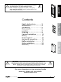
SRS–210W-C Cabinet SRS–210W-B Baffle SRS–210W-G Grille Installation Instructions Important Safety Instructions 1. Read Instructions 2. Keep these Instructions 3. Heed all Warnings. 4. Follow all Instructions 5. Do not use this apparatus near water. 6. Clean only with dry cloth. 7. Do not install near any heat sources such as radiators, heat registers, stoves, or other apparatus (including amplifiers) that produce heat. 8. Unplug this apparatus during lightning storms or when unused for long periods of time. 9. Refer all servicing to qualified service personnel. Servicing is required when the apparatus has been damaged in any way, such as a power-supply cord or plug is damaged, liquid has been spilled or objects have fallen into the apparatus, the apparatus has been exposed to rain or moisture, does not operate normally, or has been dropped. 10. Ventilation — The apparatus should be situated so that its location or position does not interfere with its proper ventilation. For example, the apparatus should not be situated on a bed, sofa, rug, or similar surface that may block any ventilation openings; or placed in a built-in installation such as a bookcase, cabinet, or closed equipment rack that may impede the flow of air through ventilation openings. 11. Power Sources — The apparatus should be connected to a power supply only of the type described in these operation instructions or as marked on the apparatus. 12. Power Cord Protection — Power-supply cords should be routed so that they are not likely to be walked upon or pinched by items placed upon or against them, paying particular attention to cords at plugs, convenience receptacles, and the point where they exit the apparatus. 13. Non-use Periods—The power cord of the apparatus should be unplugged from the outlet when unused for a long period of time. 14. Object and Liquid Entry — Care should be taken so that objects do not fall into and liquids are not spilled into the inside of the apparatus. 15. Servicing — The user should not attempt to service the apparatus beyond those means described in this operating manual. All other servicing should be referred to qualified service personnel. 16. To Prevent Electric Shock, do not use this polarized plug with an extension cord, receptacle or other outlet unless the blades can be fully inserted to prevent blade exposure. Pour préevenir les chocs électriques ne pas utiliser cette fiche polariseé avec un prolongateur, un prise de courant ou une autre sortie de courant, sauf si les lames peuvent être insérées à fond sans laisser aucune pariie à découvert. 17. Grounding or Polarization — Precautions should be taken so that the grounding or polarization means of the Component is not defeated. This apparatus does not exceed the Class A/Class B (whichever is applicable) limits for radio noise emissions from digital apparatus as set out in the radio interference regulations of the Canadian Department of Communications. ATTENTION — Le présent appareil numérique n'émet pas de bruits radioélectriques dépassant las limites applicables aux appareils numériques de class A/de class B (selon le cas) prescrites dans le règlement sur le brouillage radioélectrique édicté par les ministere des communications du Canada. User's Manual Cabinet The SubRosa subwoofer is a finely tuned system and should only be used with the Sunfire SRA-2700EQ companion amplifier. Using any other amplifier will offer inferior performance and may void your warranty. Contents Baffle Install Safety Instructions............. 2 Introduction....................... 4 Unpacking......................... 5 Dimensions....................... 6 Location............................. 7 Framing............................. 9 Cabinet installation............ 10 Wiring................................ 11 Final rough-in.................... 12 Horizontal mounting.......... 15 Baffle installation............... 17 Grille installation................ 20 Warranty............................ 23 Grille Install WARNING:THIS SUBWOOFER SYSTEM IS CAPABLE OF PRODUCING VERY HIGH SOUND PRESSURE LEVELS. YOU MUST TAKE EVERY PRECAUTION TO PROTECT YOUR HEARING FROM PERMANENT DAMAGE. For more information on this and other Sunfire products, please visit our website: www.sunfire.com User's Manual Introduction Introduction Thank you for purchasing this Sunfire XT Series SubRosa™ Subwoofer. We hope you enjoy it and the music it makes as much as we have enjoyed creating it for you. System components The required components for a functioning SubRosa in-wall system are: • SRS-210W-C In-wall cabinet and hardware. • SRS-210W-B Front baffle containing two woofers, the I-BEAM™ anti-shake device, and a crossover network. • SRS-210W-G Grille assembly • SRA-2700EQ Amplifier and its room equalization measurement microphone The breakthrough features of the subwoofer include: • I-BEAM™ anti-shake mechanism to reduce wall vibration • Dual ten-inch, High Back-emf woofers with neodymium magnets for low-profile •2700W Tracking Downconverter™ companion amplifier • Fully automatic room equalization The SubRosa subwoofer is a finely tuned system and should only be used with the Sunfire SRA-2700EQ companion amplifier. Using any other amplifier will offer inferior performance and may void your warranty. About this installation guide This guide contains instructions for installing the SubRosa in-wall cabinet into various locations, and installing the front baffle assembly, and the grille assembly. For information regarding the operation of the system, please refer to the user's guide that comes with the companion SRA-2700EQ amplifier. Tools and experience required The cabinet should only be installed by qualified and experienced professional installers. General construction tools are required for framing wood studs, gluing and screwing the cabinet in place, and applying sheetrock. User's Manual The cabinet may be mounted vertically between wall studs. The width is ideal for fitting between vertical 2x4 studs, spaced 16 inches apart. It may also be fitted horizontally. A cardboard debris shield is supplied to fill the front aperture and prevent any dust, paint, or debris from entering during installation and sheetrock finishing. Strips of foam material are supplied to fit between the cabinet and the studs and sheetrock. Contents of each package SRS–210W-C cabinet • Cabinet assembly Dimensions 44.50" x 14.25" x 3.5" 1,130.3 mm x 362 mm x 88.9 mm Weight 23.30 lb (10.6 kg) • • • • • Debris shield 12 foam strips 1" x 5" 8 foam strips 1" x 8" Plastic rivets for debris shield 12 wood screws SRS–210W-B baffle assembly • Baffle assembly Dimensions 26.75" x 11.75" x 3.25" 679.5 mm x 298.5 mm x 82.6 mm Weight 29 lb (13.2 kg) • 14 Allen head screws and washers (8-32 x 1.25") The cabinet should be firmly and permanently joined to the studwork and sheetrock using woodscrews and glue. The woofer baffle assembly is screwed to the front of the cabinet once the sheetrock is in place. A grille frame and grille are added to finish the installation. A paint shield is supplied so that you can easily paint the grille at the same time as the walls are painted. Unpacking Two people are required to gently lift out the cabinet and the baffle assembly from their shipping boxes. Remove all the packing material. Your Sunfire subwoofer should reach you in perfect condition. If you do notice any shipping damage, please contact Sunfire immediately. Make sure that you keep your sales receipt. It is the only way to establish the duration of your Limited Warranty and it may come in useful for insurance purposes. The serial number for the SubRosa subwoofer is printed on the front label of the woofer assembly. User's Manual SRS–210W-G grill assembly • Grille frame Dimensions 28.80" x 13.8" x 0.7" 731.5 mm x 350.5 mm x 17.78 mm (includes drywall spacer) Weight 2.00 lb (0.9 kg) • Grille Dimensions 26.5" x 11.5" x 0.75" 673.1 mm x 292.1 mm 19.1 mm Weight 0.6 lb (0.27 kg) • • Paint shield 12 Allen head screws SRA–2700EQ amplifier • SubRosa amplifier Dimensions 1.75" (1U) x 17" x 15" 44.5 mm x 431.8 mm x 381 mm Weight 18.4 lb. (8.35 kg) • Room measurement microphone with stand and cord • AC power cord •2 rack-mount brackets Introduction Installation overview Dimensions Front View Side View Back View 44.500 in/ 1,130.3 mm 35.590 in/ 904 mm 8.830 in/ 224.3 mm 26.76 in/ 679.7 mm 10.717 in/ 272.2 mm 13.045 in/ 331.343 mm 14.250 in/ 362 mm 3.533 in/ 89.7 mm 0 1.261 in/ 32.1 mm 0 3.500 in 88.9 mm Front Cutout required in wall to fit woofer assembly 11.784 in/ 299.3 mm User's Manual Location The suggestions below will typically result in outstanding performance. However, although low frequencies are non-directional, factors such as room reflections, standing waves, resonance and absorption will strongly affect your subwoofer’s performance. Since your SubRosa subwoofer is designed to be professionally installed into your wall, engineering services from your authorized Sunfire dealer and/or outside acoustical resources should be considered to ensure optimum performance. The SubRosa SRA-2700EQ amplifier’s Auto EQ feature will tailor the sound to the room for optimum performance in the location you choose. Keep the subwoofer at least two or three feet away from any TV screen, computer, VCR or magnetic tapes and discs. This will reduce the chance of the magnetic fields upsetting the TV screen or erasing your magnetic media. Corner installation Installing the subwoofer on the front wall, towards the corner will reinforce the low frequencies. This is best suited for: • Rooms larger than 200 square feet where a single subwoofer will be used • For dedicated home theaters • For listeners who enjoy “heavy” bass. User's Manual Corner location Center location Installing the subwoofer closer to the center of the front wall will still provide adequate bass, but will tend to be less “heavy” and somewhat tighter. This is ideally suited for: • For rooms smaller than 200 square feet • Dedicated music listening rooms. Central location Using Two Subwoofers If you wish to use two subwoofers, the sound output will double. Locating the subwoofers on the front wall, with one towards each corner will provide more flexibility in crossover points, without causing localization that can happen with subwoofers located on side and rear walls. Sunfire preamplifiers and receivers feature multiple subwoofer outputs for these applications. If your preamplifier has a single sub/LFE output, use a Y cable to split it into two outputs. Corner location for two subwoofers User's Manual Framing Vertical mounting Due to residential construction methods, vertical mounting of the cabinet is recommended. The subwoofer cabinet will fit between 2 x 4 inch studs on 16 inch centers. Horizontal mounting is also possible, but needs additional framing steps. See page 15 for horizontal mounting details. Notes: • Use the illustrations as a guide, but follow all local building codes regarding the actual framing methods. • The insulation stuffed inside the cabinet is required for proper operation. Do not remove the insulation during the cabinet installation. 1. It is recommended that you add a horizontal brace below the cabinet to raise it above the height of the finished floor and baseboard molding. This will prevent accidental nail punctures in the cabinet. 2. Add a horizontal brace above the subwoofer cabinet, leaving enough room to make your speaker wire connections to the push-terminals. 3. Add further horizontal braces at either side of the cabinet, but make sure that they are at different heights to randomize wall resonances. 4. Attach self-adhesive foam strips to the cabinet wherever there will be contact with the studs or sheetrock. Use longer strips for the sides, and shorter strips for the front face and the shorter side resting against the lower horizontal brace. 2 3 3 1 4 Typical vertical framing User's Manual Cabinet Installation 1. With the help of an assistant to lift the cabinet, check the fit of the cabinet into the framing. Use wood shims if there is any gap between the cabinet sides and the vertical studs. 2. If it makes it easier, you can connect the wiring to the cabinet before you secure it in place. See the next page for details. 3. When you are happy with the fit of the cabinet, apply wood glue, such as Liquid Nails™ along the cabinet sides. Fit the cabinet into the framing until its front face is flush with the front face of the framing. 4. Use a level to check that the cabinet is vertical. 5. Use six woodscrews (supplied) or more on each side to secure the cabinet in place. Do not screw into any of the joints of the cabinet. The cabinet walls are 3/4 inch thick, so make sure the screws do not pass all the way through. (The supplied screws will not pass through, if used with standard 2x4 studs.) Gluing and screwing the cabinet in place 10 User's Manual Wiring 1. Install the speaker wires following all local codes for electrical wiring installation. Use class 2 wiring, and 12 gauge is recommended, 16 gauge is the minimum. 2. Follow common low voltage practices like avoiding high voltage electrical wiring, or crossing them perpendicularly. This will reduce the chance of picking up hum or other interference. 3. Make the speaker wire connections to the subwoofer terminal cup, observing the correct polarity. The terminals are spring-loaded. 4. Secure the wire to the studs with electrical staples to prevent rattles and movement in operation. 5. Do an electrical continuity test to make sure the connections are good from the amplifier-end of the speaker wire to the ends of the two pre-installed wires coming out from the inside of the subwoofer. Temporarily remove the cardboard debris shield to reach the wires. 6. Use caulk to seal the nearest cable holes to the cabinet. This will prevent air movement and secure the cables in place. Due to the nature of subwoofers, it is a good idea to secure the wiring from vibration as much as possible. Do not have the weight of the cables hanging on the terminals. caulk Close-up of the spring-loaded connections Connecting speaker wire to the subwoofer User's Manual 11 Final Rough-in 1. Make sure the debris shield is fitted into the cabinet opening using the plastic push rivets supplied. This will prevent dust and sheetrock debris from entering the cabinet. Debris shield 12 User's Manual Sheetrock installation 1. Apply glue to the framing surrounding the cabinet. Also apply glue to the front surface of the cabinet, wherever it will be in contact with the sheetrock. glue glue Applying glue for sheetrocking continued.. User's Manual 13 3. Fit the sheetrock in place with sheetrock screws spaced 4 inches apart. 4. Carefully cut away the sheetrock to reveal the cabinet's aperture. Now that you can see the location better, add screws to secure the sheetrock to the front face of the subwoofer cabinet. Make sure that no screws pass close to the speaker wires or the terminal cup. 6. Leave the cardboard debris shield in place until you are ready to install the woofer baffle assembly. It can be removed by cutting it and carefully pulling out the rivets holding it in place. 7. See page 17 for details regarding the installation of the woofer baffle assembly and grille frame assembly. 5. With the cardboard debris shield in place, the walls can be painted and finished as required. Sheetrock over the subwoofer installation 14 User's Manual Horizontal mounting In this position, the subwoofer's longest side is horizontal. This may be required for some installations, although it requires more framing work. The procedure for mounting is basically the same as the vertical mounting. 2. Attach the self-adhesive foam strips (supplied) to the cabinet wherever there will be contact with the studs or sheetrock. Use longer strips for the sides, and shorter strips for the front face and the shorter vertical side. 1. The cabinet should be mounted off the floor as shown, to prevent nails from puncturing the cabinet during baseboard installation. 2 2 Typical horizontal framing User's Manual 15 3. With the help of an assistant to lift the cabinet, check the fit into the framing, and use shims if required. 4. Wiring the subwoofer is the same as described previously, except that there is not much room to make the connections to the binding posts. 5. Use wood glue, such as Liquid Nails™ along the cabinet top and side. Fit the cabinet into the framing until its front face is flush with the front face of the framing. 6. Use a level to make sure the cabinet is horizontal. 7. Use six woodscrews or more along the top, and a few into the side to secure the cabinet in place. If pos- sible, add a few screws to secure the bottom face of the cabinet. You may have to angle them in, but do not screw in to any of the cabinet joints. The cabinet walls are 3/4 inch thick, so make sure the screws do not pass all the way through. 8. Do an electrical continuity test to make sure the connections are good from the amplifier-end of the speaker wire to the ends of the two pre-installed wires coming out from the inside of the subwoofer. 9. Finishing with sheetrock is the same as described for vertical mounting. Fit the debris shield before starting the sheetrock installation. 10. See the next page for details regarding the installation of the woofer baffle assembly and grille frame assembly. Screwing and gluing the subwoofer in place 16 User's Manual Woofer baffle installation With the cabinet installed, and all the sheetrock, finishing and decorating done, the woofer baffle can be installed. The woofer baffle assembly consists of the following components already installed: • The baffle, upon which all the components are assembled • Two subwoofer drivers • I-BEAM™ anti-shake device • Crossover board Subwoofer driver I-BEAM™ anti-shake device Subwoofer driver crossover board Baffle Exploded view of the woofer baffle assembly (it is supplied all assembled and wired) User's Manual 17 Baffle installation procedure 1. Remove the debris shield from the front of the in-wall cabinet. You can do this by cutting the cardboard with a sharp knife and pulling out the cardboard pieces and the plastic rivets holding it in place. Do not cut the two wires inside the cabinet, and do not remove any soundproofing material. 2. With the help of an assistant, hold the baffle assembly close to the in-wall cabinet. 3. Connect the two wires from the inside of the cabinet to the two push-terminals on the crossover board, following this diagram: Red Wire (Positive +) Black Wire (Negative –) Attaching the cabinet wires to the crossover board fixed to the woofer baffle assembly (I-BEAM omitted for clarity) Removing the debris shield 18 User's Manual 4. Secure the woofer baffle assembly to the in-wall cabinet using 14 Allen-head screws and washers supplied. Make sure the two wires do not get pinched. 5. Before putting the grille frame and grille on, test the subwoofer to verify that all the connections are made correctly. See the user's guide that comes with your SubRosa amplifier. It contains information regarding the use of the subwoofer and the equalization procedure. The woofer baffle assembly in place Installing the woofer baffle assembly User's Manual 19 Grille installation With the woofer baffle installed, and the subwoofer tested, the grille can now be installed. Painting The grille assembly consists of the following components: • The grille frame. This screws to the woofer baffle and holds the grille in place. It forms a nice frame around the subwoofer opening in the wall, hiding the sheetrock edges. • The grille. This pushes into the grille frame, covering the woofer baffle assembly and the grille frame screws from view. • A paint shield is supplied to cover the woofer baffle when painting. This allows you to paint the frame and grille at the same time the walls are painted. The frame and grille can be painted to match the decor before they are installed. They come already powder coated, and can accept a wide range of finishes. Clean them first, then take them to a well-ventilated area and paint with care to achieve a good finish. If you prefer to paint the frame and grille when they are in place on the walls, the details are shown on the next page. Top view Grille 20 Grille frame Paint shield User's Manual Installing the grille assembly 1. Secure the grille frame to the woofer baffle using 12 screws supplied in the grille package. Location of the grille frame screws 6. Carefully press the grille into the frame, and make sure it is fully pressed home on all sides. The grille installed into the frame 2. If you have already painted the frame and grille, please jump to step 6. 3. Fit the supplied cardboard paint shield into the frame to cover the woofers and baffle. Press the grille in place temporarily. 4. Paint the frame and grille to match the wall and decor. 5. When the paint is dry, carefully remove the grille and discard the paint shield. (It is important to remember this step!) User's Manual 21 Conclusion This completes the SubRosa in-wall subwoofer installation. For details regarding the operation of the subwoofer and the automatic equalization procedure, please refer to the user's guide that comes with the Sunfire SubRosa SRA-2700EQ amplifier. © 2007 Sunfire Corporation. All rights reserved. Sunfire Corporation reserves the right to improve its products at any time. Therefore, specifications and installation details are subject to change without notice. Manual 913-142-00 Rev A 22 User's Manual Limited Warranty Sunfire Corporation is proud of its products which have been built with care using advanced technology and premium component parts. Your unit has been crafted to perform properly for many years. Sunfire Corporation offers the following Warranty to you, the owner of a new Sunfire product: The Sunfire Corporation Warranty for the SubRosa Subwoofer is in effect for FIVE years from the date of original retail purchase. The Sunfire Corporation Warranty covers defects in materials and workmanship. The following, however, are excluded: Some states do not allow limitations on how long an implied warranty lasts and/or do not allow the exclusion or limitation of incidental or consequential damages, so the above limitations or exclusions may not apply to you. This Warranty gives you specific legal rights, and you may also have other rights which vary from state to state. We suggest that you attach your purchase receipt to this Warranty and keep these in a safe place. Thank you for your choice of a Sunfire Corporation product. Service Assistance a) Damage caused during shipment. We suggest that you read the Limited Warranty completely to fully understand your Warranty/Service coverage. b) Damage caused by accident, misuse, abuse of operation contrary to the instructions specified in the Sunfire Corporation user’s manual If your Sunfire Corporation product ever requires service, write to us, or call: Sunfire Corporation Technical Services Department P.O. Box 1589 Snohomish, WA 98290 Tel (425) 335-4748 Fax (425) 335-4746 www.sunfire.com c) Units where the serial number has been defaced, modified or removed, d) Damage resulting from modification or attempted repair by any person not authorized in writing by Sunfire Corporation. e) Units purchased from unauthorized dealers. You will be directed to an authorized Sunfire Corporation Service Station or receive instructions to ship the unit to the factory. Please save the original shipping carton and packing materials in case shipping is required. Always use the original packaging materials and method, or the finish may be damaged. Please do not ship Parcel Post. The Sunfire Corporation Warranty extends to the original owner or subsequent owner(s) during the five year warranty period so long as the original dated purchase receipt is presented whenever warranty service is required. All implied warranties, including warranties or merchantability and fitness for particular purposes, are limited in duration to the five year length of this Warranty, unless otherwise provided by state law. Sunfire Corporation’s liability is limited to the repair or replacement, at our option, of any defective product and shall not in any event include property or any other incidental or consequential damages which may result from the failure of this product. User's Manual NOTE: Before sending in your unit for repair, you must call Sunfire for return authorization. Include a complete description of the problem, indicating how you have it connected, the associated equipment in your system and a copy of your purchase receipt. Initial shipping costs are not paid by Sunfire Corporation; return ground shipping costs will be prepaid if repairs were covered by the scope of this Warranty. 23 SRS–210W-C Cabinet SRS–210W-B Baffle SRS–210W-G Grille Manual 913-142-00 Rev A