1
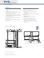
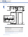
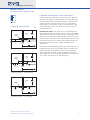
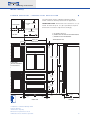
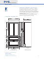
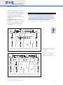
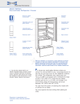
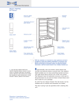
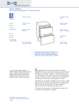
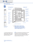
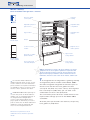
Planning Information
Model 736TC(I)
Over-and-Under Refrigerator | Freezer
Model 736TC
Electronic digital
control panel
Seamless
molding
Adjustable spill-proof
glass shelves
Adjustable dairy
compartment
Egg container
Adjustable door
shelves
Crisper
Location of serial
number
Magnetic door /
drawer gaskets
Automatic ice maker
(Model 736TCI)
Upper freezer
storage drawer
Front venting with
removable kickplate
Lower freezer
storage drawer
Model 736TCI
with Ice Maker
With the installation of a harness kit, these appliances are Star-K
compliant to meet strict religious regulations in conjunction with
specific instructions found on star-k.org. You may purchase this
harness kit through your Sub-Zero dealer. To obtain local dealer
information, visit the Locator section of our website, subzero.com.
The Sub-Zero Model 736TC and
736TCI integrated design accepts custom
wood or stainless steel door and drawer
panels. Stainless steel panels and handles
are available as sales accessories in three
finishes—classic, platinum and carbon.
IMPORTANT NOTE: When planning for
custom door panels for Model 736TC or
736TCI, refer to "Integrating Cabinetry" in
the Integrated General Applications
section of this Planning Guide. These
pages explain in detail areas you need to
plan for. Panel sizes for Model 736TC and
736TCI are exactly 9" (229) wider that
those for other Integrated tall units.
Dimensions in parentheses are in
millimeters unless otherwise specified.
10/05
The Integrated line of refrigeration is growing—literally
and figuratively. We’ve introduced the Model 700BC
that takes integrated refrigerator and freezer space to
the base unit and now we have grown the same
concept to 36" (914). Yes, that’s correct, the Integrated
line is not only 27" (686) wide, you can order a tall
combination unit that is 36" (914) wide.
This unit will be perfect for those smaller kitchens that
required more storage space than the Model 700TC
could offer.
All of the panel specifications are identical, except they
have grown 9" (229) wider.
1
Planning Information
Model 736TC(I)
F E AT U R E S
Tall 36" (914) wide combination unit with
upper cabinet refrigerator and freezer storage
drawers
Model 736TCI has automatic ice maker
Integrated design for "point-of-use" refrigeration anywhere in the home
Dual refrigeration system with two distinct
temperature zones ensures the freshest food
and energy efficiency
Electronic digital controls are up front and
easy to use
Flat to the ceiling bright lighting in cabinet
and drawers
Door alarm will let you know with an audible
beeping if a door or drawer is left open
Adjustable spill-proof glass shelves
Refrigerator deli drawer for storage of
smaller items
The exclusive dual action hinge has a built-in
90˚ door stop
Meets strict Department of Energy
requirements
UL approved for US and Canada
Two, five and twelve year residential
warranty – exclusions apply; warranty
information can be found on our website,
subzero.com
OVERALL DIMENSIONS
36"
24"
(914)
(UNIT DIMENSION)
(610)
(UNIT DIMENSION)
TOP OF
ROUGH
OPENING
14"(356)
15/16"
(33)
24"
DOOR MOUNTING
DETAIL
(610)
DOOR / DRAWER
CLOSED
DOOR / DRAWER
CLOSED
80"*
(2032)
90˚
3/8"
7713/16"*
(10)
(1976)
191/2"*
341/2"* (495)
(876)
105˚
347/8" (886)
131/4"
1/2" (337)
(13)
DRAWER MOUNTING
DETAIL
90˚ DOOR OPENING
341/2"*
101/4"
MAXIMUM DOOR OPENING
7"*
(178)
TOP VIEW
*DOOR / DRAWER PANEL THICKNESS NOT INCLUDED – DIMENSION WILL VARY WITH INSTALLATION
(876)
(260)
203/8"
93/4"
(518)
(248)
4"
FRONT VIEW
(102)
SIDE VIEW
*1/2" (13) +_ ADJUSTMENT IN LEVELING LEGS
Dimensions may vary by ± 1/8" (3).
Dimensions in parentheses are in
millimeters unless otherwise specified.
2
Planning Information
Model 736TC(I)
S P E C I F I C AT I O N S
Model 736TC(I)
Over-and-Under Refrigerator /Freezer
Overall Width
36" (914)
Overall Height
80" (2032)
Overall Depth
24" (610)
MODEL OPTIONS
Refrigerator Capacity
Over-and-Under
Refrigerator/Freezer
Over-and-Under
Refrigerator/Freezer
with Automatic Ice Maker
736TC
13.5 cu ft (383 L)
Freezer Capacity
6.9 cu ft (195 L)
Minimum Height (levelers in)
736TCI
Door Clearance
34 1/2" (876)
Drawer Clearance
19 1/2" (495)
Electrical Requirements
PA N E L O P T I O N S
Plumbing Requirements
Integrated (custom panels)
Classic Stainless Steel Finish
/S
Water Supply
Platinum Stainless Steel Finish
/P
Annual Energy Usage
Carbon Stainless Steel Finish
/B
Shipping Weight
Stainless steel door and drawer front
panels are ordered and shipped as sales
accessories and include tubular handles.
79 1/2" (2019)
Special Note
115 V AC, 60 Hz, 15 amp circuit
1/ 4"
copper line
20–100 psi
569 kWh / $ 48
480 lbs (218 kg)
Door and drawer panels and handles are
available in three stainless steel finishes
Specifications are subject to change without notice.
ACCESSORIES
Tubular handles in classic,
platinum and carbon stainless
steel
Shelf and deli drawer assembly
Dozen egg container with lid
Dual installation heater kit
(TTDUAL or BBDUAL)
Accessories are available through your
Sub-Zero dealer. To obtain local dealer
information, visit the Locator section of
our website, subzero.com.
Dimensions in parentheses are in
millimeters unless otherwise specified.
3
Planning Information
Model 736TC(I)
I N S TA L L AT I O N S P E C I F I C AT I O N S
TOP VIEW
11/2"
(38)
25"
(635)
TOP VIEW
6"
ANTI-TIP
BRACKET
(152)
18" (457)
CL
20" (508)
27"
13 1/2"
ANTI-TIP
BRACKET
18" (457)
(686)
27"
CL
(686)
WATER LINE
SIDE ENTRY
LOCATIONS
(343)
WATER LINE
BOTTOM ENTRY
LOCATION
11/2"
11/2"
(38)
(38)
36"
25"
(914)
(635)
LOCATE ELECTRICAL WITHIN
SHADED AREA – ORIENT GROUND
PRONG TO RIGHT AS SHOWN
LOCATE WATER LINE
(REAR ENTRY) WITHIN
SHADED AREA
ANTI-TIP
BRACKET
80"
(2032)
4 1/2"
3"
(114)
(76)
1/4"
(6)
17 1/2" (445)
13 1/2"
(343)
2 1/2" (64)
3/4"
(19)
20" (508)
NOTE: ANTI-TIP BRACKET MUST BE INSTALLED TO
PREVENT UNIT FROM TIPPING FORWARD
ANTI-TIP
BRACKET
FRONT VIEW
WATER LINE
SIDE ENTRY
LOCATION
SIDE VIEW
Dimensions may vary by ± 1/8" (3).
DIMENSIONS
Finished Rough Opening Width
36" (914)
Finished Rough Opening Height
80" (2032)
Finished Rough Opening Depth
25" (635)*
Location of Electrical
Within shaded area
Location of Plumbing (Model 736TCI only)
Within shaded area
* The depth of the Model 736TC(I) is 24" (610) from the front of the unit to its back. Your design
may necessitate moving the unit back, or cabinets forward to achieve a flush fit. This will require
a minimum rough opening depth of 25" (635).
See Installation Instructions shipped with unit for detailed specifications.
Dimensions in parentheses are in
millimeters unless otherwise specified.
4
Planning Information
Model 736TC(I)
I N S TA L L AT I O N N OT E S
Refer to the illustrations and specifications
for overall dimensions, finished rough opening
dimensions and installation specifics.
The depth of Model 736TC (I) is 24" (610)
from the front of the unit to its back. Your
design may necessitate moving the unit back,
or cabinets forward to achieve a flush fit. This
will require a minimum rough opening depth of
25" (635). Refer to the installation illustration.
The anti-tip bracket must be installed to
prevent the unit from tipping forward.
Integrated units are compatible with virtually
any style of cabinetry. They can be used with
framed as well as frameless cabinets.
Refer to the full-scale illustrations at the end
of this section for specifics on panels and door
openings.
Door panels can grow beyond the 80" (2032)
height to accommodate any size of door as long
as you stay below the recommended door panel
weight limit of 53 lbs (24 kg). Door panels must
be a minimum of 5/8" (16) thick.
The weight of each drawer panel cannot
exceed 16 lbs (7 kg). Drawer panels must be a
minimum of 5/8" (16) thick.
For the bottom drawer, the maximum panel
height is 16 11/16" (424). You must keep a
minimum space of 4" (102) clear below the
bottom edge of the lower drawer panel, so the
unit can be properly vented. In addition, any
decorative base molding must be removable for
possible servicing and cleaning of the
condenser.
We recommend using D-style handles, which
should be located on the opposite side from the
hinge, centered on the cabinet door and the top,
center area of the drawer panel.
Two Integrated units may be installed next to
one another. Refer to page 11 for additional
information.
For Integrated models with an automatic ice
maker, rough in the water supply line. Connect a
1/4" OD copper line to the house supply, being
sure to use an easily accessible shut-off valve
between the supply and the unit. This shut-off
valve should not be installed behind the unit.
Dimensions in parentheses are in
millimeters unless otherwise specified.
Do not use self-piercing valves. A saddle
valve kit (4200880) is available from your
Sub-Zero dealer. To obtain local dealer information, visit the Locator section of our website,
subzero.com.
A line filter is required when water conditions have a high sediment content. The ice
maker operates on water pressure of 20 psi
(1.4 bar) to 100 psi (6.9 bar). In some cases a
reverse osmosis water filter system may not be
able to maintain the minimum water pressure
consistently.
When routing the water through the side
walls, you must place the water line within 1/2"
(13) of the floor and as close as possible to the
back wall. The line must be routed around the
anti-tip bracket so it clears the bracket and
leveling feet of the unit. Refer to the installation
illustration for placement of the water line.
Do not route water supply line in front of the
compressor tray. The tray must be slid forward
for service.
Regardless of the routing, allow for 27"
(686) of excess copper tubing to remain outside
the wall or floor for easy connection to the unit,
as shown in the installation illustration.
A 115 volt, 6OHz, 15 amp circuit breaker and
electrical supply are required. A separate circuit,
servicing only this appliance is necessary.
All Integrated models are equipped with a
power supply cord with a 3-prong grounding
plug, which must be plugged into a mating
3-prong grounding type wall receptacle. The
electrical outlet must be placed so the grounding prong is to the right of the thinner blades.
The outlet must be flush with the back wall.
Locate electrical within the shaded area shown
in the installation illustration.
Do not use an extension cord or two prong
adapter. Electrical ground is required.
You must follow all National Electrical Code
regulations. In addition, be aware of local codes
and ordinances when installing your service.
The Integrated Installation Guide packed with
the appliance will give you step-by-step procedures for making sure the unit is installed
properly.
5
Planning Information
Model 736TC(I)
I N T E G R AT I N G C A B I N E T RY
C A B I N E T RY A P P L I C AT I O N S
Integrated refrigeration is compatible with virtually any
style and look of cabinetry. The models can be used with
framed as well as frameless cabinets. Because of the
precise application and the look you may want to achieve,
there are important questions you need to answer before
ordering panels for the doors and/or drawers. As you look
at styles of cabinets, keep some important facts in mind:
Weight Limitations – The door panel cannot exceed
53 lbs (24 kg) and each drawer panel must not exceed
16 lbs (7 kg).
Panel Thickness – Door and drawer panels must be a
minimum of 5/8" (16) thick.
The height of the door panel can grow beyond 45 3/8"
(1153) and exceed the 80" (2032) overall height as long as
you stay below the recommended door panel weight limit.
The toe kick clearance can vary with the height of the
lower drawer panel; the maximum panel height is 16 11/16"
(424). You must keep a minimum space of 4" (102) clear
below the bottom edge of the lower drawer panel so the
unit can be properly vented.
We recommend using D-style handles. For the cabinet
door, handles must be located near the edge of the panel
opposite the hinge, centered top to bottom. Locate
handles in the top center area of the drawer panels.
IMPORTANT NOTE: The depth of each Integrated unit is
24" (610) from the front of the unit to its back. You must
allow for the thickness of the panel you are applying when
planning for the finished rough opening depth if you want
the front panel to be flush with surrounding cabinetry. You
may have to move the unit back into drywall or bring the
cabinets forward to achieve a flush fit.
As the reveal between cabinets and the Integrated unit
decreases, the potential exists for severe finger
pinching or crushing if a hand or fingers are placed in
the opening when the door is closing.
Dimensions in parentheses are in
millimeters unless otherwise specified.
6
Planning Information
Model 736TC(I)
I N T E G R AT I N G C A B I N E T RY
F R A M E D C A B I N E T RY A P P L I C AT I O N S
Framed cabinetry applications present you with different
questions to address. The illustrations on this page show
common applications of framed cabinetry. These are not
meant to be the only alternatives, but are suggestions
from designers around the country. Also refer to the fullscale illustrations at the end of this section for specifics
on door openings.
FRAMED CABINETRY
SUB-ZERO
UNIT
CABINET
FRAME
CABINET
DOOR
24
(610)
TO WALL
PANEL
1/8" (3)
REVEAL
IMPORTANT NOTE: The depth of each Integrated unit is
24" (610) from the front of the unit to its back. You must
allow for the thickness of the panel you are applying when
planning for the finished rough opening depth if you want
the front panel to be flush with surrounding cabinetry. You
may have to move the unit back into drywall or bring the
cabinets forward to achieve a flush fit. Refer to the
illustrations.
36
(914)
1
Traditional Frame – full overlay.
3
T
SUB-ZERO
UNIT
CABINET
FRAME
24
Illustrations on the following pages give dimensions for an
Integrated base or tall unit installed within a framed cabinetry beaded inset application. Review the illustrations,
giving particular attention to the overall panel specifications. Also refer to the full-scale illustrations at the end of
this section for specifics on door openings.
(610)
TO WALL
1
CABINET
DOOR
PANEL
1/8" (3)
REVEAL
3
36
(914)
Traditional Frame – standard overlay.
S
T
SUB-ZERO
UNIT
24
(610)
TO WALL
CABINET
FRAME
1
CABINET
DOOR
1/8" (3)
REVEAL
PANEL
3
36
(914)
Traditional Frame – 3/8" (10) offset.
Dimensions in parentheses are in
millimeters unless otherwise specified.
7
Planning Information
Model 736TC(I)
F R A M E D C A B I N E T RY – B E A D E D I N S E T A P P L I C AT I O N
24"
The illustration shows a Model 736TC(I) installed
within a framed cabinetry beaded inset application.
(610)
SUB-ZERO
UNIT
CABINET DOOR
TO WALL
IMPORTANT NOTE: Dimensions are based on a 1/8" (3)
reveal. A reveal of up to 1/4" (6) is possible, but panel
dimensions need to be adjusted accordingly.
DOOR PANEL
A
A
A) ALL REVEALS ARE 1/8" (3)
B) DRAWER RAILS ARE ATTACHED TO DRAWER FRONTS
C) BOTTOM RAIL MUST BE REMOVABLE
36"
TOP VIEW
(914)
*DIMENSIONS MAY VARY
35 3/4" (908)
PANEL WIDTH
11/2"
(38)
47 7/8"
84"
(1216)
(2624)
SHADED AREA
INDICATES STATIONARY
STYLES AND RAILS
80"*
(2032)
A
B
13 9/16"
(345)
A
B
341/2"
(876)*
15 1/16"
11/2"
(38)
(383)
A
C
4"*
36"
(914)
11/2"
(38)
11/2"
(38)
FRONT VIEW
(102)
4" (102)
24"
(610)
SIDE VIEW
Installation of a Model 736TC(I) within
framed cabinetry.
*Dimensions may vary.
Dimensions in parentheses are in
millimeters unless otherwise specified.
8
Planning Information
Model 736TC(I)
F R A M E L E S S C A B I N E T RY A P P L I C AT I O N S
The illustration below shows a hypothetical installation
of a Model 736TC(I) within frameless cabinetry. Review
the illustration, giving particular attention to the overall
panel specifications. Also refer to the full-scale illustrations
at the end of this section for specifics on door openings.
IMPORTANT NOTE: Dimensions are based on a 1/8" (3)
reveal. A reveal of up to 1/4" (6) is possible, but panel
dimensions need to be adjusted accordingly.
FRAMELESS CABINETRY
35 3/4"* (908)
24"
PANEL WIDTH
(610)
A
45 3/8"
(1153)
80"*
(2032)
79 7/8"*
(2029)
A
13 9/16"
(345)
A
341/2"
(876)*
16 11/16"*
(424)
4"*
(102)
36"
(914)
TOE KICK
SIDE VIEW
FINISHED OPENING
A) ALL REVEALS ARE 1/8" (3)
*DIMENSIONS MAY VARY
Installation of a Model 736TC(I) within
frameless cabinetry.
*Dimensions may vary.
Dimensions in parentheses are in
millimeters unless otherwise specified.
9
Planning Information
Model 736TC(I)
PA N E L C O N S I D E R AT I O N S
The illustrations below provide panel
width dimensions for installation of a
single Model 736TC(I) and for
installing two Model 736TC(I) units
side by side.
When 5/8" (16) or thicker panels are used and a reveal
less than 1/4" (6) is maintained, the door panels may
cause damage to the Sub-Zero unit when the door is
open at the maximum 105˚ door stop. You should use
the built-in 90˚ door stop to prevent damage.
IMPORTANT NOTE: Dimensions are
based on a 1/8" (3) reveal. A reveal of
up to 1/4" (6) is possible, but panel
dimensions need to be adjusted
accordingly.
36
(914)
* 1 (3) min
8
REVEAL
* 1 (3) min
8
REVEAL
35 43 (908)
3
4 (19) PANEL
34 87 (886)
25
(635)
CABINETRY
OR SIDE
PANEL
24
(610)
25
(635)
APPLIANCE
DOOR WIDTH
CABINETRY
OR SIDE
PANEL
TO BACK
OF UNIT
SUB-ZERO
UNIT
*SUBTRACT PANEL WIDTH FROM CABINETRY OPENING TO DETERMINE ACTUAL WIDTH OF REVEAL
*
72 (1829)
* 1 (3) min
8
REVEAL
13
(910)
35 16
13
(910)
35 16
* 1 (3) min
8
REVEAL
* 1 (3) min
8
REVEAL
3
4 (19) PANEL
25
25
C (635)
CABINETRY
OR SIDE
PANEL
24
(610)
Panel width dimensions for
installation of two Model
736TC(I) units side by side.
3
4 (19) PANEL
(635)
CABINETRY
OR SIDE
PANEL
Panel width dimensions for
installation of a single Model
736TC(I).
DOOR
DOOR
SUB-ZERO
UNIT
SUB-ZERO
UNIT
TO BACK
OF UNIT
*SUBTRACT PANEL WIDTH FROM CABINETRY OPENING TO DETERMINE ACTUAL WIDTH OF REVEAL
Dimensions in parentheses are in
millimeters unless otherwise specified.
10
Planning Information
Model 736TC(I)
CABINETS
25
(635)
I N S TA L L AT I O N O P T I O N S
36
(914)
TOP VIEW
3
Installation without side
panels.
C
The illustrations on this page show some typical
installations and their dimension considerations.
The depth dimension in the illustrations may vary
depending on cabinet styles, treatment of countertops or other design options.
IMPORTANT NOTE: The depth of each Integrated
unit is 24" (610) from the front of the unit to its
back. Your design may necessitate moving the unit
back, or cabinets forward to achieve a flush fit. This
will require a minimum rough opening depth of 25"
(635). Refer to the illustrations.
CABINETS
25
(635)
3
36
(914)
MINIMUM 5/8" (16) SIDE PANELS
D UA L I N S TA L L AT I O N S
Installation with side panels.
CABINETS
25
(635)
T
If two or more Integrated models are installed side
by side where there is 2" (51) or less of space
between the units, a heater kit is recommended—
TTDUAL for a Model 736TC(I) installed with another
tall unit or two Model 736TC(I) units installed side
by side and BBDUAL for a base unit and a Model
736TC(I) unit installed side by side. These optional
components are available through your Sub-Zero
dealer. To obtain local dealer information, visit the
Locator section of our website, subzero.com.
72
(1829)
TOP VIEW
Installation of two units side by side.
C
CABINETS
25
(635)
3
M
36
(914)
MINIMUM
5/8"
(16) SIDE PANELS
Installation at end of run.
Dimensions in parentheses are in
millimeters unless otherwise specified.
11
Planning Information
Model 736TC(I)
D O O R PA N E L H E I G H T
The height of the door panel can grow beyond 45 3/8"
(1153) and exceed the 80" (2032) overall height, as long as
you stay below the recommended door panel weight limit
of 40 lbs (18 kg) for 27" (868) wide units and 53 lbs
(24 kg) for the Model 736TC(I).
The illustration below shows how the panel may grow and
what you need to consider doing to finish the area in back
of the door panel.
IMPORTANT NOTE: The valance you use to finish the area
behind the door panel must stay behind the front plane of
the finished molding as shown in the illustration.
IMPORTANT NOTE: The depth of each Integrated unit is
24" (610) from the front of the unit to its back. Your
design may necessitate moving the unit back, or cabinets
forward to achieve a flush fit. This will require a minimum
rough opening depth of 25" (635). Refer to the illustration.
U P P E R VA L E N C E D E TA I L
25
(635)
TO WALL
1 21 (38)
DECORATIVE VALANCE
CANNOT EXTEND BEYOND
THE FRONT OF THIS PLANE
DECORATIVE VALANCE
1
4
(6)
REMOVABLE MOLDING
BY SUB-ZERO
45 83
(1153)
TO
BOTTOM
OF
DOOR
PANEL
TOP HINGE
80*
(2032)
TO
FLOOR
*FINISHED HEIGHT OF 80" (2032) IS TO TOP OF SUB-ZERO MOLDING
Dimensions in parentheses are in
millimeters unless otherwise specified.
12
Planning Information
Model 736TC(I)
TOE KICK CLEARANCE
The toe kick clearance can vary with the height of the
lower drawer panel; the maximum panel height is 16 11/16"
(424).
IMPORTANT NOTE: You must keep a minimum space of
4" (102) clear below the bottom edge of the lower drawer
panel so the unit can be properly vented. In addition, any
decorative base molding must be removable for possible
servicing and cleaning of the condenser.
The illustration below shows the area below the lower
drawer where the operating mechanical equipment of the
Integrated unit is housed.
IMPORTANT NOTE: The depth of each Integrated unit is
24" (610) from the front of the unit to its back. Your
design may necessitate moving the unit back, or cabinets
forward to achieve a flush fit. This will require a minimum
rough opening depth of 25" (635). Refer to the illustration.
TO E K I C K A R E A D E TA I L
9
1016
(268)
PANEL
1
2
(13)
11
1616
(424)
PANEL
11
9 16
(246)
10
(254)
OPTIONAL
BASE MOLDING MUST
BE REMOVABLE
4
24
(102)
(610) TO WALL
2 85 TO 4
(67)
(102)
Dimensions in parentheses are in
millimeters unless otherwise specified.
FLOOR
13
Planning Information
Model 736TC(I)
SUB-ZERO
DOOR
F U L L - S C A L E T E M P L AT E
FRAMED CABINETRY
IMPORTANT NOTE: The depth of each Integrated
unit is 24" (610) from the front of the unit to its
back. Your design may necessitate moving the unit
back, or cabinets forward to achieve a flush fit.
24
T
(610)
TO BACK
OF UNIT
LINE OF INTERFERENCE*
105˚ maximum door opening – 1/4 scale (top view)
LINE OF INTERFERENCE*
AT MAXIMUM DOOR OPENING
MOUNTING BRACKET SCREW
1 (3)
MIN.
8
REVEAL
PANEL
3
4 (19)
34 87 (886)
APPLIANCE DOOR WIDTH
SUB-ZERO DOOR
24
(610)
TO BACK
OF UNIT
LINE OF INTERFERENCE*
SIDE MOLDING AND
INSTALLATION HARDWARE
PROVIDED BY SUB-ZERO
FLUSH
FURNITURE
FINISH
Door closed – full scale (top view)
Dimensions in parentheses are in
millimeters unless otherwise specified.
*If the panel is thicker than 3/4" (19), it is recommended that you
utilize the built-in 90˚ door stop to prevent damage to the panel
and face frame.
14
Planning Information
SUB-ZERO DOOR
Model 736TC(I)
3/4" (19) DOOR
F U L L - S C A L E T E M P L AT E
COUNTERTOP
PANEL
SIDE PANEL
FRAMELESS CABINETRY
IMPORTANT NOTE: The depth of each Integrated
unit is 24" (610) from the front of the unit to its
back. Your design may necessitate moving the unit
back, or cabinets forward to achieve a flush fit.
24
(610)
TO
WALL
LINE OF INTERFERENCE*
105˚ maximum door opening – 1/4 scale (top view)
Adjacent side panel and countertop application
1 (3)
MIN.
8
LINE OF INTERFERENCE*
AT MAXIMUM DOOR OPENING
REVEAL
MOUNTING BRACKET SCREW
3
4 (19)
PANEL
34 87 (886)
APPLIANCE DOOR WIDTH
SUB-ZERO DOOR
24
(610)
TO BACK
OF UNIT
LINE OF INTERFERENCE*
SIDE MOLDING AND
INSTALLATION HARDWARE
PROVIDED BY SUB-ZERO
Door closed – full scale (top view)
Dimensions in parentheses are in
millimeters unless otherwise specified.
*If the panel is thicker than 3/4" (19), it is recommended that you
utilize the built-in 90˚ door stop to prevent damage to the panel
and face frame.
15