1
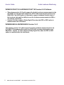
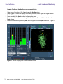
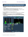
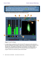
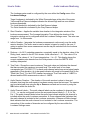
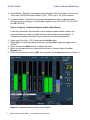
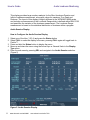
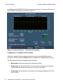
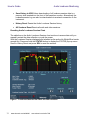
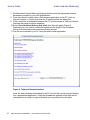
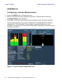
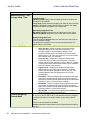
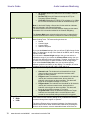
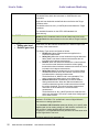
How to Guide Audio Loudness Monitoring WFM6120/7020/7120 & WVR6020/7020/7120 Version 6.0.2 Software WFM8300/8200 & WVR8300/8200 Version 1.6.3 Software How to Guide Audio Loudness Monitoring WFM6120/7020/7120 & WVR6020/7020/7120 Version 6.0.2 Software This release version 6.0.2 adds support for Audio Loudness measurements to the ITU-R BS.1770 standard with support for ATSC A/85 recommended practice and EBU R128. The ALOG option is required to support Loudness Session chart of the loudness data and the ability to save the loudness measurements to USB or via network connection. Version 6.0.2 also supports Dolby Digital Plus when the DPE or DDP option is installed within the instrument. WFM8300/8200 & WVR8300/8200 Version 1.6.3 This release version 1.6.3 adds support for Audio Loudness measurements to the ITU-R BS.1770 standard with support for ATSC A/85 recommended practice and EBU R128. Version 1.6.3 also supports Dolby Digital Plus when the DPE or DDP option is installed within the instrument. 2 www.tektronix.com\wfm8000 www.tektronix.com\wfm7100 How to Guide Audio Loudness Monitoring How to Configure the Audio Loudness monitoring 1. Select one of the tiles (1,2,3,4) and press the Audio button 2. Select FULL to make the display full screen, pressing FULL again will toggle back to FlexVu™. 3. Press and hold the Audio button to display the menu. 4. Move up and down the menu using the Arrow Keys or General Knob to the Loudness Meter menu. 5. Enter the sub menu by pressing SEL and navigate to the Program selection. (Figure 1) Figure 1. Audio Display with Audio Loudness Meter 3 www.tektronix.com\wfm8000 www.tektronix.com\wfm7100 How to Guide Audio Loudness Monitoring Note:- The Audio Loudness meter is available for Analog, AES, Embedded and Dolby inputs. The Loudness meter is not available in Embedded 16-Ch mode. How to Quickly Configure the Loudness Measurements Presets for ATSC or EBU Standards. Within the Config menu of the instrument there are a variety of settings for the Loudness measurements within the Loudness Settings menu. To simplify the operation of the instrument Loudness Presets are available to quickly configure the unit to the appropriate standard recommendations. 1. Press the Config button to enter the configuration menu. 2. Move up and down the menu using the Arrow Keys or General Knob to the Loudness Settings menu 3. Press SEL to enter the sub menu and navigate to the Loudness Preset menu. 4. Depending on the user requirements you can select ATSC A/85, EBU R128 (draft), EBU R128 (wide) or IEC 61672. Navigate to the appropriate selection and press SEL to enable this preset. Figure 2. Loudness Preset Configuration menu. 4 www.tektronix.com\wfm8000 www.tektronix.com\wfm7100 How to Guide Audio Loudness Monitoring Note:- When the Loudness preset is selected within the Loudness Settings menu. Settings that are changed within the Loudness Settings menu by the loading of the Loudness preset will be shown in yellow text. Information regarding the settings of the Loudness presets can be obtained by pressing the HELP button on the front of the instrument. Elements of Audio Display with Loudness Measurements. Figure 3. Audio Tile Display. 1. Loudness Meter is enabled from within the Audio Tile menu and can be selected to show the Loudness for the program, a channel pair or disabled and not displayed within the audio tile. The Program Loudness (Pl) is a summation of a number of audio channels. The channels that are included in the summation are indicated within the audio display by green channel labels. The channels that are not included in the program loudness are indicated by white channel labels. 5 www.tektronix.com\wfm8000 www.tektronix.com\wfm7100 How to Guide Audio Loudness Monitoring The Loudness meter scale is configured by the user within the Config menu of the Loudness Settings. Target Loudness is indicated by the White Diamond shape at the side of the meter. Yellow and Blue Diamond shapes indicates the allowed high and low user defined loudness thresholds. Too Loud threshold is indicated by the Red Diamond shape. Too Quiet threshold is indicated by the Grey Diamond shape. 2. Short Duration – Applies the variable time duration to the integration window of the loudness measurement. The Average Integration Time defines the duration of the integration window and is configured within the Loudness Settings menu. The value can range from 1 to 60 seconds. 3. Infinite Duration - Integrates the loudness measurement continuously over the audio session duration. The audio session can be started, stopped or reset by the user. If gating is applied then some measurement results may be excluded from the loudness measurements. 4. Dialnorm – An AC-3 metadata parameter, numerically equal to the absolute value of the Dialog Level, carried in the AC-3 bit stream. Valid values are 1 – 31. The value of 0 is reserved. The values of 1 to 31 are interpreted as –1 to –31. This display shows the current metadata value decode from the Dolby stream or from the SMPTE 2020 ancillary data packet. 5. True Peak – Shows the current maximum True peak value and indicates the channel that has recorded the maximum true peak level. The audio level is four times oversampled per ITU-R BS 1771 for each audio channel and shows actual signal peaks regardless of their duration. An in-bar peak indicator will persist at the peak level for the "Peak Hold Time". For the ATSC standard a maximum True Peak value of -2dBFS is allowed and the EBU recommends a value of -1dBFS. 6. Audio Session Duration – The duration of the audio session is show in time and indicates how long the audio session has been running since the last reset. The session can be started and stop using the Up or Down arrows and can be reset by using the SEL button within the audio tile. 7. Audio Channel Labels – The audio channel labels can be numbered in channel pairs (1,2,3…) or can be configured to show the surround channel labels (L, C, R, Ls, Rs, Lfe..). The audio channel labels below the audio bars indicate whether this channel is included within the audio Loudness summation. A Green channel label indicates that the audio channel is included in the Loudness summation. Whereas a White channel label indicates that the audio channel is not included in the Loudness summation. The summation of the number of channels can be configured by the user within the Loudness Settings menu. 6 www.tektronix.com\wfm8000 www.tektronix.com\wfm7100 How to Guide Audio Loudness Monitoring 8. Audio Ballistic - Specifies the response characteristics of the level meters. Choices are True Peak, PPM (Peak Program Meter) Type 1, PPM Type 2, VU, and Loudness. 9. Loudness Ballistic - Specifies the response characteristics of the Loudness meters. Choices are Short Average, Long Average, Ungated Long, IEC 61672 F, IEC 61672 S and EBU R128 M. How to Configure Loudness Readouts within Audio Display A user may specifically be interested in the Loudness measurements made by the instruments and to be able to quickly read the values within the audio display. To configure this display as shown in Figure 4 perform the following operations. 1. Select one of the tiles (1,2,3,4) and press the Audio button 2. Select FULL to make the display full screen, pressing FULL again will toggle back to FlexVu™. 3. Press and hold the Audio button to display the menu. 4. Move up and down the menu using the Arrow Keys or General Knob to the Aux Display menu. 5. Enter the sub menu by pressing SEL and navigate to the Loudness selection (Figure 4) Figure 4. Loudness Readouts within Audio Display. 7 www.tektronix.com\wfm8000 www.tektronix.com\wfm7100 How to Guide Audio Loudness Monitoring This display provides large number readouts for the Short Loudness Duration and Infinite Loudness measurement, along with values for maximum True Peak and Dialnorm. The layout of this display is slightly different in the WFM/WVR 8000 series and includes a measurement of the Loudness Range which is defined within EBU R128 and quantifies the variation of the loudness measurement. The Loudness Range measurement is based on the statistical distribution of loudness within a program. Audio Session Display How to Configure the Audio Session Display 1. Select one of the tiles (1,2,3,4) and press the Status button 2. Select FULL to make the display full screen, pressing FULL again will toggle back to FlexVu™. 3. Press and hold the Status button to display the menu. 4. Move up and down the menu using the Arrow Keys or General Knob to the Display Type menu. 5. Enter the sub menu by pressing SEL and navigate to the Audio Session selection. (Figure 5) Figure 5. Audio Session Display 8 www.tektronix.com\wfm8000 www.tektronix.com\wfm7100 How to Guide Audio Loudness Monitoring The audio session display contains a variety of summary information on each channel of the audio signal for the number of clips, mute, over and silence events that have occurred during the audio session Run Time. Additionally the maximum Peak and High audio level for each channel are also displayed. Note:- The Peak value in the audio session display is the True Peak audio level measurement and the High audio level value is based on the ballistic used for the audio level. The True Peak measurement is based on a four times oversampling of the audio signal as specified in ITU-R BS.1771. For audio loudness measurements a calculation for each channel and channel pairs is shown in the audio session display, along with the Program Loudness for the short and infinite duration. The Program Loudness measurement is based on a summation of a number of the audio channels and the duration of the measurement. The information on the number of channels summed together is provided within the Chans: display and the Short PD: label indicates the duration of the short period used for the Short term Loudness measurement. The infinite duration of the Loudness measurement is based on the Run Time of the audio session and can be stopped, started or reset by the user. Note:- To stop or start the audio session press the up or down arrows in either the audio tile or audio session display. Press SEL to reset the Run Time of the audio session in either the audio or audio session display. Loudness Session The ALOG option is required for the Loudness Session that displays a trend chart of the loudness measurements and the ability to save the data to USB or download to a PC via a network connection. How to Configure the Loudness Session Display 1. Select one of the tiles (1,2,3,4) and press the Status button 2. Select FULL to make the display full screen, pressing FULL again will toggle back to FlexVu™. 3. Press and hold the Status button to display the menu. 4. Move up and down the menu using the Arrow Keys or General Knob to the Display Type menu. 5. Enter the sub menu by pressing SEL and navigate to the Loudness Session selection. (Figure 5). There are two types of charts available within the instrument. A trend chart (Figure 6) that shows a graph of the loudness measurements for the last 90 or 180 seconds and a bar chart that shows the maximum and minimum loudness value during each bar period and can show the loudness variations from nine minutes to a six hour duration within 9 www.tektronix.com\wfm8000 www.tektronix.com\wfm7100 How to Guide Audio Loudness Monitoring the WFM and WVR 6000/7000 Series instruments and from 7.5 minutes to 30 hours on the WFM/WVR 8000 Series instruments (Figure 7). Figure 6. Loudness Session – Trend Chart 90 Seconds. Configuration of Loudness Session Display. With the Loudness Session display selected as the active tile (Bright Blue border around tile). Push and hold the Status button to display the Loudness Session menu. The following selections are available within this menu. 10 Mute Alarms Alarm reporting can be temporarily muted. Graph Scale The horizontal scale of the chart can be changed from 0-90 and 180 seconds trend chart to nine minute to a six hour bar chart. Graph Gain The vertical gain of the chart can be changed between 0-60, 8-40 and 12-36dB. www.tektronix.com\wfm8000 www.tektronix.com\wfm7100 How to Guide Audio Loudness Monitoring Save History to USB Allows downloading of all loudness session data to a memory stick inserted into the front of the waveform monitor. Alternatively the loudness session log can also be downloaded via a network connection to the instrument. History Reset Resets the Audio Loudness Session history. All Sessions Reset Resets all audio and video sessions. Resetting Audio Loudness Session Chart The statistics on the Audio Loudness Session chart continue to accumulate until you manually restart the data collection or cycle the power. With the Loudness Session displayed and selected as the active tile (Bright Blue border around tile). Press and hold the STATUS button to display the STATUS pop-up menu. Scroll to History Reset and press SEL to reset the session. Figure 7. Loudness Session Bar Chart six hour duration. 11 www.tektronix.com\wfm8000 www.tektronix.com\wfm7100 How to Guide Audio Loudness Monitoring Elements of Loudness Session Display. 1. Loudness History: Shows a graphical display of Loudness measurements over time. A trend chart is available for durations of 90 or 180 seconds and a bar chart between nine minutes to a six hour duration within the WFM and WVR 6000/7000 Series instruments and from 7.5 minutes to 30 hours on the WFM/WVR 8000 Series instruments. 2. Scale: Indicates the time interval over which the loudness measurements are made. This can be configured within the Loudness Session menu. When a Bar chart is selected the top left of the chart shows the duration of each bar and an update icon shows when the next bar will be added to the chart (Figure 7). 3. LKFS short Loudness measurement based on duration of short period. 4. LKFS inf. Infinite Loudness measurement based on duration of audio session. 5. Dialnorm is the metadata value that is present either within the Dolby data stream or carried as an Ancillary data packet per SMPTE2020. 6. True Peak is the maximum true peak value recorded by the audio meters. More detailed information on the true peak level of each channel is displayed within the audio session. 7. Max Value The maximum Loudness value recorded within the loudness session. 8. Min Value The minimum Loudness value recorded within the loudness session. 9. Loudness Session Avg. The Loudness session average that is a summed average of all the values recorded in the session. 10. Channel Summation Shows the summation of audio channels currently used to compute the Loudness average. 11. Short Period Displays the current duration of the short period Loudness average. 12. Target Value Displays the current user defined Target Loudness level. 13. Loudness Session Time Displays the current duration of the Loudness Session since last reset. 12 www.tektronix.com\wfm8000 www.tektronix.com\wfm7100 How to Guide Audio Loudness Monitoring Saving the Loudness Measurements Session Data. If you are using a WFM waveform monitor then you can save the Loudness measurement data to a USB stick in the following way. 1. Insert a memory stick into the front of the waveform monitor. You may have to wait a moment for the memory stick to be mounted within the instrument. To check the status of the USB device press the MAIN button and verify that the USB stick is mounted. If the USB stick is mounted then the menu will show USB Unmount that indicates the next action will unmounts the drive. If the USB device is not installed and indicates USB Mount then press SEL to mount the device or check the status of the drive. You may have to try a different device if the USB stick is not recognized by the unit. 2. Select the Loudness Session as the active tile (Bright Blue border around tile). Press and hold the STATUS button to display the STATUS pop-up menu. 3. Navigate to Save History to USB using the arrow keys or general knob. 4. Press SEL to automatically save the Loudness session data to the USB memory device. A progress bar will be shown in the status menu to indicate the transfer of the file. 5. The Loudness Session data will be automatically stored in a folder using the Instrument name InstrumentName LoudnessHist. Within this folder a file will be created of the Loudness History using the Instrument Name, Date and Time of the instrument as the file name. 6. Once the data is saved to the memory stick please remember to Unmount the device which can be done under the Main button menu. In order to prevent loss of data on the USB device. You can also download the Loudness Session data use a PC and a network connection to the instrument. 1. Connect the instrument to a PC through an ethernet hub or a direct connection with a crossover cable to back of the instrument. 2. To allow network access to the instrument, you need to set the IP address. Network addresses can be assigned either automatically (DHCP) or manually. If your network does not use DHCP, you will have to manually enter the address for the instrument. Your LAN administrator will be required to provide a manual fixed IP address for you to use on a company network. 3. Press the CONFIG button to display the configuration menu and navigate to Network Settings. Press SEL to enter the submenu. 4. Navigate to Web Enable using the arrow keys or general knob and ensure On is selected. 5. Set the IP Config Mode to Manual or DHCP depending on your network setup. If using DHCP you can skip steps six and seven. 6. Select IP Address if entering an address manually and then use the dialog box to enter the values required using the arrow keys to navigate and SEL to set between each value. 13 www.tektronix.com\wfm8000 www.tektronix.com\wfm7100 How to Guide Audio Loudness Monitoring 7. Similarly select Subnet Mask and Gateway Address with the appropriate network parameters provided by your LAN Administrator. 8. Once the network is setup open a Web browser application on the PC (such as Internet Explorer or Firefox) and enter the IP address within the dialog box. 9. If the connection is established between the PC and instrument a Tektronix Remote Interface web page should be displayed. 10. Select View Loudness History (text, html) from this web page (Figure 8). Depending on your network connection speed and the length of the Loudness History this download process can take several minutes. 11. The file can be saved to your PC using the web browser application. Figure 8. Tektronix Remote Interface. Once the data has been downloaded to the PC the html file can be imported directly into a spreadsheet application. Using the spreadsheet application the data can be manipulated in a variety of ways and charts can be produced from the data. 14 www.tektronix.com\wfm8000 www.tektronix.com\wfm7100 How to Guide Audio Loudness Monitoring APPENDIX A1 Configuring Loudness Measurements 1. Press the CONFIG button to display the menu. 2. Move up and down the menu using the Arrow Keys or General Knob to select the Loudness Settings menu (Figure 9). 3. Press SEL to enter sub menus and scroll up and down to select the desired function. The following information is provided on each function available within the Loudness Settings menu. This information is also available by pressing Help button on the instrument or browsing the On-line documentation when connected to the instrument via a network connection. Figure 9. Loudness Setting Configuration menu. 15 www.tektronix.com\wfm8000 www.tektronix.com\wfm7100 How to Guide Function Loudness Preset Audio Loudness Monitoring Description Loudness presets allow you to quickly configure the instrument's loudness measurement to comply with specific standards bodies. Press SEL to load the selected loudness preset. The configuration that changes as a result of the loading of the preset will be showing in yellow with the Loudness settings configuration menu. The follow are the available Loudness Preset selections: ATSC A/85 EBU R/128 (draft) EBU R/128 (wide) IEC 61672 These loudness preset reconfigure the settings of the loudness measurements in the following way: ATSC A/85 This preset loads a configuration in compliance with ATSC A/85 and configures the following settings: Loudness Filter/ Measure - LKFS (BS.1770) Momentary Integration Time - IEC 62672 (125ms) Average Integration Time - 10 seconds Channel Weighting - ITU-R BS.1770 Custom Mask - Press SEL Target Loudness -24LKFS Target Loudness High 2LU Target Loudness Low 2LU Gating Type - Disabled Safety Gating Level -99LKFS Relative Gate level 0LU Loud A-D Conversion -20dBFS EBU R/128 (draft) This preset loads a configuration in compliance with EBU R/128 and configures the following settings: Loudness Filter/ Measure - LKFS (BS.1770) Momentary Integration Time - EBU R/128(draft) (400ms) Average Integration Time - 3 seconds Channel Weighting - ITU-R BS.1770 Custom Mask - Press SEL Target Loudness -23LKFS Target Loudness High 1LU Target Loudness Low 1LU Gating Type - Relative Safety Gating Level -99LKFS Relative Gate level -8LU Loud A-D Conversion -18dBFS EBU R/128 (wide) This preset loads a configuration in compliance with EBU R/128 and configures the following settings: Loudness Filter/ Measure - LKFS (BS.1770) Momentary Integration Time - EBU R/128(draft) (400ms) Average Integration Time - 3 seconds 16 www.tektronix.com\wfm8000 www.tektronix.com\wfm7100 How to Guide Audio Loudness Monitoring Channel Weighting - ITU-R BS.1770 Custom Mask - Press SEL Target Loudness -21LKFS Target Loudness High 1LU Target Loudness Low 1LU Gating Type - Relative Safety Gating Level -99LKFS Relative Gate level -8LU IEC 61672 This preset loads a configuration in compliance with EBU R/128 and configures the following settings: Loudness Filter/ Measure - Leq(A) Momentary Integration Time - IEC 62672 (125ms) Average Integration Time - 10 seconds Channel Weighting - Custom Custom Mask - Press SEL Target Loudness -24dBFS Target Loudness High 2dB Target Loudness Low 2dB Gating Type - Disabled Safety Gating Level -99dBFS Relative Gate level -0dB Loud A-D Conversion -20dBFS Loudness Filter/Measure The Loudness Filter and Measurement selection controls which of the three weighting filters are applied to the audio loudness measurement, and is used by the loudness algorithm to calculate the audio loudness. Selections for this parameter are: LKFS (ITU-R BS.1770) - LKFS measurements using the Kweighting filter as specified by ITU-R BS.1770. This filter is preferred for surround sound programs, and is specified by ATSC and EBU recommendations for monitoring program loudness. Leq (Linear) - Leq measurements using a weighting filter with a flat response. Leq(A) - Leq measurements using the A-weighting filter, which more closely matches the frequency response of the human ear. The filter selection applies to several areas: The Surround Sound display The Bar displays when displaying the loudness ballistic The Program or Channel Pair audio loudness bar displays Loudness measurements and readings in the Audio Display, Audio Session Display, Audio Loudness Display, and Dolby Status Displays. The Audio Loudness Session display The currently selected filter is shown within the Audio Display above 17 www.tektronix.com\wfm8000 www.tektronix.com\wfm7100 How to Guide Momentary Integ. Time Average Integ. Time Audio Loudness Monitoring the Loudness Bar or within the Surround Sound display. The Loudness Filter & Measure menu has the following selections. Loudness Filter: LKFS (ITU-R BS.1770) Loudness weighting filter that complies with ITU-R BS.1770 standard. Leq (Linear) Linear Loudness weighting filter that has a flat response. Leq(A) A-Weighted Loudness filter that has a response that closely matches the frequency response of the human ear. Momentary Integration Time: IEC 62672 (125ms) Integration time of audio bars is set to 125ms EBU R/128 (400ms) Integration time of audio bars is set to 400ms Loudness Ballistic Channel Weighting Custom Mask Average Integration Time: This value sets the Short duration over which the time interval is set for the Loudness Average. The range for this setting is from one second to 60 seconds. The default value is 10 seconds. The user can select a variety of Ballistics for the Loudness Meter Short Average - Applies a variable time duration to the integration window of the loudness measurement. The Average Integration Time defines the duration of the integration window and is configured within the Loudness Settings menu. The value can range from one to 60 seconds with a default value of 10 seconds. Long Average - Integrates the loudness measurement continuously over the audio session duration. The audio session can be started, stopped or reset by the user. If gating is applied then some measurement results may be excluded from the loudness measurements. Ungated Long - Integrates the loudness measurement continuously over the audio session duration. The audio session can be started, stopped or reset by the user. This Loudness ballistic does not apply gating to the overall measurement. IEC 62672F- This time-weighted function applies to the audio level meters and affects how quickly the bars rise when the signal level increases and fall when the signal level decreases. Loudness F has a 0.125 second time constant. IEC62672S - This time-weighted function applies to the audio level meters and affects how slowly the bars rise when the signal level increases and fall when the signal level decreases. Loudness S has a 1 second time constant. EBU R/128M - This measurement applies the M ballistic per EBU R/128 with a 400ms integration time. The Channel Weighting allows you to select a number of channels (L, R, C, Lfe, Ls, Rs, Lb, Rb, S, M, Le, Re) that are used in the Program Loudness calculation in the Audio Session screen and Loudness meter. There are several selections available: Custom Selects the channel based on the Custom Mask selected by the user. 18 www.tektronix.com\wfm8000 www.tektronix.com\wfm7100 How to Guide Audio Loudness Monitoring All Channel Selects All Channels to be included in Channel Weighting. Exclude LFE Select All Channels except the LFE (Low Frequency Effects Channel). ITU-R BS.1770 Applies ITU-R BS.1770 weighting of +1.5dB to the surround channels and includes all channels except LFE. Note: In the Audio Display a Green label for the audio bar indicates that it is included in the Channel Weighting. The Audio Session and the Loudness Session display provide status information of the channels included in the Channel Weighting. Meter Scaling Alarm Thresholds The Custom Mask menu selection allows the user to customize the included channels when Custom is selected for Channel Weighting. You can change the range and limits of the Audio bar display in the Meter Scaling menu. The meter scaling choices are: Normal Custom Height Custom Offset Graticule Step Size If you use the Normal settings, then you will see 70 dB of range for the bars. For digital input, the top of the scale will be DBFS, and for analog inputs it will be dBu. If you chose the Custom Height settings, then you can reduce or expand the range. If you choose the Custom Offset setting, then you can shift the displayed levels up and down. Together, these allow you to zoom in on one region or shrink the bars to cover a large range. If you select Graticule Step Size, then you can select spacing between graticules and labels on the display. For example, at a value of 6 there will be a label at 0dB, -6dB, -12dB, and so on. Audio Loudness configurable Alarm Thresholds are: Target Loudness High Low Channel Loud: The loudness level threshold for a single channel, audio source, above which the loudness value triggers an alarm condition. Program Loud: The loudness level threshold for all channels used by the Loudness measurement, above which the loudness value triggers an alarm condition. This alarm will trigger an in-bar audio message of Too Loud. Program Quiet: The loudness level threshold for all channels used by the Loudness measurement, below which the loudness value triggers an alarm condition. This alarm will trigger an in-bar audio message of Too Quiet. Target/DN Delta: When the difference between the Target loudness level threshold and the current Dialnorm value exceed the user defined setting an alarm will be triggered. The Target Loudness of an audio program is defined as the specified value for the Anchor Element (Dialog Level), established to facilitate content exchange from supplier to operator. The Anchor Element is the perceptual loudness of a reference point element around which other elements are balanced in producing the final mix of the content, or that a reasonable viewer would focus on 19 www.tektronix.com\wfm8000 www.tektronix.com\wfm7100 How to Guide Audio Loudness Monitoring when setting the volume control, as defined in ATSC standard A/85. The default value within the instrument is -24LKFS and is user selectable. High and Low thresholds are defined above and below the Target Loudness value. The default values are 2LU (+/-2LKFS) above and below the Target Loudness. Set 0LU Mark to Gating Type Safety gate level Relative gate level Loud A-D Conversion For detailed information on the ATSC A/85 standard visit www.atsc.org. The Loudness meter can have the 0LU configured to either the Full Scale top of the Loudness meter or the 0LU mark can be set to the Target Loud value that is based on the user defined Target Loudness value. Loudness Gating refers to the practice of excluding moments of low level audio from the loudness measurement, in order to improve the accuracy of the measurement. The Gating Type can be configured as follows: Disabled No Gating measurements are applied to the Loudness measurement. Safety Only When the current loudness level goes below the Safety Gate Level these loudness measurements are not included in the loudness measurement. Relative. When the difference between the current loudness level and the overall loudness exceed the relative gating threshold then these loudness measurement values will not be included in the loudness measurement. Safety Gate Level The loudness level set for Safety Gating measurements below which the loudness values will not be included within the loudness measurement. The default limits is -99LKFS and is user selectable. This value is used when Gating type is set to Safety Only. Relative Gate Level The loudness level set for Relative Gating measurements. When the difference between the current measurement and the overall measurement exceed the relative threshold. Then these loudness measurement values will not be included in the overall loudness measurement. The default limits is -8LU (-8LKFS) below the loudness level and is user selectable. This value is used when Gating type is set to Relative mode. Some loudness measurements, such as the LKFS measurement defined in ITU-R BS.1770, are defined in terms of digital fullscale rather than on analog signal levels. The Loudness A-D Conversion parameter allows you to specify what digital signal level an analog voltage of 0 dBu shall be converted to for the purpose of making digitally-defined measurements. In general, it is recommended that this parameter have the same value as the Digital Audio Test Level. Common values for this parameter are: 20 www.tektronix.com\wfm8000 www.tektronix.com\wfm7100 How to Guide Audio Loudness Monitoring In North America, -20 dBFS In Europe, -18 dBFS This parameter only affects digital loudness measurements such as LKFS. It does not affect audio bar readouts. References WFM6000/7000 Series Waveform Monitors WVR6000/7000 Series Waveform Monitors Data Sheets, Fact Sheets and additional product materials can be found www.tektronix.com/video_test/signal_monitors.html 21 www.tektronix.com\wfm8000 www.tektronix.com\wfm7100 How to Guide Audio Loudness Monitoring ASEAN / Australasia (65) 6356 3900 Austria 00800 2255 4835* Balkans, Israel and other ISE Countries +41 52 675 3777 Belgium 00800 2255 4835* Brazil + 55 (11) 3759 7600 Canada 1-800-833-9200 Central East Europe, Ukraine and the Baltics +41 52 675 3777 Central Europe & Greece +41 52 675 3777 Denmark +45 80 88 1401 Finland +41 52 675 3777 France 00800 2255 4835* Germany 00800 2255 4835* Hong Kong 400-820-5835 India 000-800-650-1835 Italy 00800 2255 4835* Japan 81 (3) 6714-3010 Luxembourg +41 52 675 3777 Mexico, Central/South America & Caribbean (52) 56 04 50 90 Middle East and Africa +41 52 675 3777 The Netherlands 00800 2255 4835* Norway 800 16098 People’s Republic of China 400-820-5835 Poland +41 52 675 3777 Portugal 80 08 12370 Republic of Korea 001- 800-8255-2835 Russia & CIS +7 (495) 7484900 South Africa +41 52 675 3777 Spain 00800 2255 4835* Sweden 00800 2255 4835* Switzerland 00800 2255 4835* Taiwan 886 (2) 2722-9622 United Kingdom & Ireland 00800 2255 4835* USA 1-800-833-9200 * European toll-free number. If not accessible, call: +41 52 675 3777 For Further Information Tektronix maintains a comprehensive, constantly expanding collection of application notes, technical briefs and other resources to help engineers working on the cutting edge of technology. Please visit www.tektronix.com Copyright © 2010, Tektronix. All rights reserved. Tektronix products are covered by U.S. and foreign patents, issued and pending. Information in this publication supersedes that in all previously published material. Specification and price change privileges reserved. TEKTRONIX and TEK are registered trademarks of Tektronix, Inc. All other trade names referenced are the service marks, trademarks or registered trademarks of their respective companies. Int/WWW 22 www.tektronix.com\wfm8000 www.tektronix.com\wfm7100 9/10 2PW-25721-1