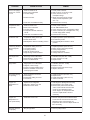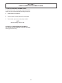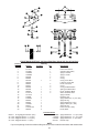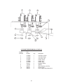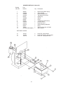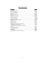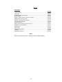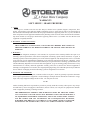
1
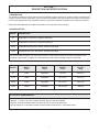
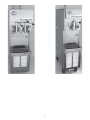
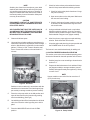
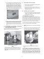
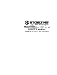
DQ - CHALLENGER SERIES
SOFT SERVE & SHAKE MACHINE
OWNER'S MANUAL
Manual No. 513561
June 03, Rev. 3
Need Parts or Service?
We stock the parts you need.
Our Technicians are factory
trained and are certified in the
Stoelting Technicare program.
CALL
Distributor: _________________________
Phone No.:
_________________________
(fill in or affix label)
Model No.: _______________________
Serial No.: _______________________
Purchase Date: ____________________
Start-Up Date:____________________
OWNER'S MANUAL
STOELTING CHALLENGER SERIES
SOFT SERVE & SHAKE FREEZERS
This manual provides basic information about the freezer and its components. Instructions and
suggestions are given covering its basic operation and care.
The illustrations and specifications are not binding in detail. We reserve the right to make changes
at any time without notice, to the freezer and its components, without incurring any obligation to equip
same on freezer components built prior to date of change.
DO NOT ATTEMPT to operate the freezer until instructions and safety precautions in this manual are
read completely and are thoroughly understood. The freezer should be operated only by qualified
personnel. If problems develop or questions arise in connection with installation, operation or
servicing of the freezer, contact your local Stoelting Distributor.
STOELTING, LLC
502 Hwy 67
Kiel, WI 53042-1600
Tele: 920-894-2293
Fax: 920-894-7029
TABLE OF CONTENTS
SECTION 1 - DESCRIPTION AND SPECIFICATIONS
1.1 Description ...................................................................................................................... 1
1.2 Specifications .................................................................................................................. 1
SECTION 2 - INSTALLATION
2.1 Shipment and Transit ........................................................................................................ 3
2.2 Installation ........................................................................................................................ 3
2.3 Remote Condenser .......................................................................................................... 5
2.4 Mix Pump Installation and Checkout (Remote Models) ...................................................... 7
SECTION 3 - OPERATING INSTRUCTIONS
3.1 Safety Information ............................................................................................................. 9
3.2 Safety Precautions ........................................................................................................... 10
3.3 Operating Controls ........................................................................................................... 11
3.4 Spigot Switch ................................................................................................................... 11
3.5 Drive Motor Overload ....................................................................................................... 11
3.6 Main Drive (CLEAN-OFF-SERVE) ................................................................................... 11
3.7 Freezing Switch ................................................................................................................ 11
3.8 Door Interlock Switch ........................................................................................................ 11
3.9 Remote Pump Switch ....................................................................................................... 11
3.10 Dispense Rate Adjuster ................................................................................................. 11
3.11 High Pressure Cut Out .................................................................................................... 11
3.12 Sanitizing Procedures .................................................................................................... 11
3.13 Initial Freeze Down and Operation .................................................................................. 12
3.14 Removing Mix From the Freezer ..................................................................................... 13
3.15 Disassembly and Assembly of Front Door (Model 217 and 237R) .................................. 14
3.16 Disassembly and Assembly of Auger ............................................................................. 16
3.17 Disassembly and Assembly of Mix Line Adaptor (Remote Models) ................................ 17
3.18 O-Ring Removal and Care ............................................................................................. 17
3.19 Cleaning of Freezer and Freezer Parts ........................................................................... 17
3.20 Sanitize Freezer Parts .................................................................................................... 18
SECTION 4 - MAINTENANCE INSTRUCTIONS
4.1 Freezer Adjustments ........................................................................................................ 19
4.2 Product Temperature Adjustment ...................................................................................... 19
4.3 Drive Belt Tension Adjustment .......................................................................................... 19
4.4 Condenser Cleaning (Air-Cooled Freezers) ..................................................................... 19
4.5 Preventative Maintenance ................................................................................................ 20
4.6 Extended Storage ............................................................................................................ 20
4.7 Troubleshooting ................................................................................................................ 20
SECTION 5 - HOW TO ORDER REPLACEMENT PARTS
5.1 How To Order Replacement Parts .................................................................................... 23
5.2 Parts List and Reference Drawings .................................................................................. 23
LIST OF ILLUSTRATIONS
Figure
Title
Page
1
Caster Options ......................................................................................................
3
2
Water Connections ................................................................................................
4
3
Electrical Connections ...........................................................................................
4
4
Auger Shaft Rotation .............................................................................................
5
5
Remote Condenser ...............................................................................................
6
6
Mix Transfer Line & Pump Installation ....................................................................
8
7
Warning Label Locations .......................................................................................
10
8
Operating Controls ................................................................................................
11
9
Air Bleed ...............................................................................................................
12
10 Pump Switch .........................................................................................................
12
11 Front Door Disassembly ........................................................................................
14
12 Spinner Assembly .................................................................................................
15
13 Auger with Rubber Rear Seal ................................................................................
16
14 Auger Disassembly ...............................................................................................
16
15 Plastic Parts ..........................................................................................................
16
16 Auger Assembly ....................................................................................................
16
17 Auger Flight Spring ...............................................................................................
17
18 Mix Line Adapter ...................................................................................................
17
19 Removing O-rings .................................................................................................
17
20 Potentiometer ........................................................................................................
19
21 Belt Adjustment .....................................................................................................
19
SECTION 1
DESCRIPTION AND SPECIFICATIONS
1.1 DESCRIPTION
The Stoelting Challenger pressurized freezers are available in water cooled or air cooled versions (completely selfcontained or with remote condensers). Some models are available with built-in hoppers or remote mix pump feed.
Freezers are equipped with fully automatic controls to provide for consistent temperature and uniformity of product.
Refer to Mix Pump Manual for complete information on the operation of the mix pump.
1.2 SPECIFICATIONS
MODEL
DESCRIPTION
217
Single Barrel - Soft Serve - Hopper Pump Style
217R
Single Barrel - Soft Serve - Remote Pump Style
225R
Single Barrel with Spinner - Shake - Remote Pump Style
237R
Twin Barrel with Twist - Soft Serve - Remote Pump Style
The above models include a 2 HP drive motor, with a 2.5 HP soft serve and 2.0 HP shake compressor. Selfcontained freezers have 6.5 gallon (24.7 liter) hopper per side, with a Stoelting model 219 mix pump.
MODEL
WIDTH
in/cm
D E P TH
in/cm
HEIGHT
in/cm
NET WT.
lb/kg
217
15/38
39.25/99.5
63.4/161
405/183.7
217R
15/38
39.25/99.5
55.7/141.4
375/170.1
225R
15/38
39.25/99.5
55.7/141.4
385/174.5
237R
16/40.6
39.25/99.7
60.75/154.3
560/254
ELECTRICAL REQUIREMENTS:
Domestic - 1 Phase, 230 volt or 3 phase, 208/230 volts, 60 hertz are available.
- Refer to electrical nameplate at the rear of the freezer for specific requirements.
- Wiring diagram is in information packet located behind left side panel, or front header panel.
1
2
SECTION 2
INSTALLATION
2.1 SHIPMENT AND TRANSIT
The freezer has been assembled, operated, and inspected
at the factory. For shipment, the freezer is placed on skids,
with small parts placed separately in boxes. Upon arrival
at the final destination, the freezer must be checked for
any damage which may have occurred during final transit.
WARNING
FREEZER MUST NOT BE ALLOWED TO TIP
MORE THAN 10°. FAILURE TO HEED THIS WARNING COULD RESULT IN THE FREEZER FALLING
ON IT’S SIDE CAUSING SERIOUS DAMAGE OR
INJURY.
C.
With the sturdy packaging used, the equipment should
arrive in satisfactory condition. THE CARRIER IS
RESPONISIBLE FOR ALL DAMAGE IN TRANSIT,
WHETHER VISIBLE OR CONCELAED. Do not pay the
freight bill until you have checked the equipment. Have
the carrier note any visible damage on the freight bill. If
concealed damage and or shortage is found later advise
the carrier within ten days and request inspection. The
customer must place claim for damage and/or shortages
in shipment with the carrier. Stoelting, Inc. cannot make
any claims against the carrier.
NOTE
Leveling is necessary for correct freezer drainage.
2.2 INSTALLATION
Installation of the freezer involves moving the freezer close
to its permanent location, removing all protective packaging, setting in place and cleaning.
A.
B.
To level turn the top part of the caster or the bottom
part of the leg in or out. Then level by placing a level
on top of the freezer at each corner.
Remove all protective packaging. Remove the hold
down bolts from the wooden pallet, and walk freezer
off the pallet.
D.
For all freezers allow a minimum of 6 inches of space
at the front and rear for air circulation. For efficient
operation, the room temperature should not be be
low 60° F (16° C) or above 90° F (32° C).
E.
For water cooled freezers, install a minimum of 1/2
inch pipe or 5/8 inch inside diameter copper water
line to the freezer. The water line must be connected
in a manner that will comply with local codes and
allow adequate room for servicing.
NOTE
All external plumbing is to be supplied by the customer.
Water lines connect to fittings at the rear of the freezer.
(See Fig.2) Connect the clean, potable, water inlet to water
source using flexible high water pressure line. Ordinary
garden hose is not recommended. Connect the water outlet to flexible plastic tubing. The outlet can be secured to
floor drain, as the outlet is clean, warm water.
The freezer is shipped without legs. To install legs,
lift freezer and screw caster, extension, or leg into
the bottom of frame at each corner. Refer to caster
and leg options in Figure 1.
Option A - Casters
Option B - Casters & Extensions
Figure 1. Caster Options
For Models DQ217, 217R, 225R, 237R
3
Water In
Water Out
Figure 2
Water Connections
Access Holes
Figure 3
Electrical Connections
4
G.
CAUTION
FLUSH ALL WATER LINES BEFORE INSTALLATION. IN NEW STORES WITH SEDIMENT IN
WATER, ADD SUITABLE FILTER OR STRAINER
TO WATER INLET. FAILURE TO FLUSH ALL
WATER LINES MAY RESULT IN EQUIPMENT
FAILURE AND EQUIPMENT DAMAGE.
F.
Check the auger shaft rotation by placing the MAIN
DRIVE switch in the CLEAN position. Auger shaft
rotation is clockwise as viewed through the clear plastic front door. If the rotation is not clockwise, turn
main electrical power OFF. Then reverse any two
electrical power lines in the junction box (three phase
only). Recheck auger shaft rotation. (Fig.4)
NOTE
Three phase freezers in areas of unbalanced electrical loads require special attention when connecting input electrical power. The unbalanced leg of
power (called wild or high) must be connected to L2
in the junction box.
Refer to nameplate at the side of the freezer for
specific electrical requirements. Connect electrical
power to the junction box at the rear of the freezer.
Bring wires into junction box through access hole in
bottom rear of freezer. (Fig.3).
ATTENTION
The 24V AC pilot circuit is wired for a 240V supply.
If this freezer is installed in a location with a 208V
supply the transformer must be rewired. Remove
the left and right side panel to access.
H.
CAUTION
ELECTRICAL TECHNICIANS MUST BE CONTINUOUSLY ALERT TO THE PRACTICE OF ALL NECESSARY SAFETY RULES AND PRECAUTIONS
WHEN SERVICING THIS EQUIPMENT AS VOLTAGES ARE PRESENT WHICH CAN CAUSE SERIOUS OR FATAL INJURY.
Remote fed freezers require an approved 1/2 inch
(12.7 mm) I.D. refrigerated mix transfer tube from
mix pump in walk in cooler to mix inlet at top of
freezer. Clamp both ends of tubing. Support to
prevent sagging and to promote total drainage when
not in use.
NOTE
Refer to the mix pump manual for complete information on the operation of the mix pump.
2.3 REMOTE CONDENSER
The remote condenser can be installed either indoors or
outdoors without additional protection required. Horizontal installation requires the liquid line connection to be
made at the bottom of the coil. There should be no obstructions to the fan within five feet of the discharge.
ELECTRICAL WIRING MATERIALS, ARRANGEMENT AND GROUNDING MUST CONFORM WITH
NATIONAL AND OTHER APPLICABLE ELECTRICAL CODES.
NOTE
There must be an adequate supply of ambient air
below 120° F (49° C). Operating above this temperature will result in loss of capacity. Guard against
recirculation due to discharge into an overhang roof
or the side of the building.
A.
Connect 230VAC, 60HZ, 1-PH to run the 1/6 HP,
2.8 AMP fan motor.
B.
Connect refrigerant lines. Use 3/8 inch (9.52 cm)O.D.
copper line only. Trap hot gas line as shown (Fig.5).
Do not trap liquid line at all. If condenser is below
the freezer, no traps are required. (Fig.5)
NOTE
Maximum line length is 50 feet (15.24 meters).
Figure 4
Auger Shaft Rotation
5
Figure 5
Remote Condenser
6
2.4 U3 MIX PUMP INSTALLATION AND CHECKOUT
(REMOTE MODELS)
A.
Follow the steps below to install the mix pump in an
upright position on the wall (allow clearance for a
mix container under pump). See Fig.6.
1. Mount by locating four (4) hole centers on cooler
wall using mounting bracket as template.
CAUTION
KNOW THE COOLER’S WALL DESIGN BEFORE
DRILLING TO PREVENT PERSONAL INJURY OR
PROPERTY DAMAGE.
2. Drill four (4) 1/2" diameter holes into cooler wall
3/4" deep.
3. Insert well-nut to flange and apply silicone sealant around outside diameter of flange and cooler
wall.
4. Repeat steps 2&3 for other located hole centers.
5. Mount bracket to cooler wall with supplied wing
screws. Hand tighten until secure.
6. Mount pump to bracket with wing nuts.
B.
Connect 1/2" (1.27cm) I.D. plastic food grade tubing
to the mix container. Secure with hose clamps. (5/
8" tubing is used with the 219 pump)
C.
Connect 1/2" (1.27 cm) I.D. plastic food grade
tubing between the large port of air/mix tee and
refrigerated mix transfer line. Secure with large hose
clamp or equivalent.
D.
Plug mix pump into a 115 volt grounded receptacle.
National sanitation foundation compliance requirements (Remote Pump)
In order to comply with the “National Sanitation Testing
Laboratory, Inc.” (NSF)code #6:
A.
This unit (remote pump) must be installed with a “NSF”
listed refrigerated mix transfer line. The mix transfer
line must be pitched to the cooler with no sags or
low points, to allow complete drainage.(Fig.6).
B.
The product at the mix pump and in transfer line must
be maintained below 41° F (5.0° C).
7
Figure 6
Mix Transfer Line
and Pump Installation
8
SECTION 3
OPERATING INSTRUCTIONS
3.1 Safety Information
WARNING Read and understand the entire manual before operating or maintaining Stoelting equipment.
This Owner’s Manual provides the operator with information for the safe operation and maintenance of Stoelting
equipment. As with any machine, there are hazards associated with their operation. For this reason safety is
emphasized throughout the manual. To highlight specific safety information, the following safety definitions are
provided to assist the reader.
The purpose of safety symbols is to attract your attention to possible dangers. The safety symbols, and their
explanations, deserve your careful attention and understanding. The safety warnings do not by themselves eliminate
any danger. The instructions or warnings they give are not substitutes for proper accident prevention measures.
SAFETY ALERT SYMBOL Indicates danger, warning or caution. Attention is
required in order to avoid serious personal injury. The message that follows the
symbol contains important information about safety.
DANGER
DANGER indicates an imminently hazardous situation, which, if not avoided, will
result in death or serious injury and equipment/property damage.
WARNING
WARNING indicates a potentially hazardous situation, which, if not avoided, may
result in death or serious injury and equipment/property damage.
CAUTION
CAUTION indicates a potentially hazardous situation, which, if not avoided, may
result in minor or moderate injury and equipment/property damage.
CAUTION
NOTICE
CAUTION indicates a potentially hazardous situation, which, if not avoided, may
result in equipment/property damage.
NOTICE indicates information or procedures that relate directly or indirectly to
the safety or personnel or equipment/property.
Safety Labels
Take notice of all warning labels on the freezer (refer to Figure 7). The labels have been put there to help you
maintain a safe working environment. The labels have been designed to withstand washing and cleaning. All labels
must remain legible for the life of the freezer. Labels should be checked periodically to be sure they have not been
damaged or removed and that they can be recognized as warning labels.
If you are in need of replacement labels, contact the authorized Stoelting distributor in your area.
9
3.2 SAFETY PRECAUTIONS
Do not attempt to operate the freezer until the safety precautions and operating instructions in the manual are read
completely and are thoroughly understood.
SAFE OPERATION IS NO ACCIDENT; observe these
rules:
A.
Know the freezer. Read and understand the operating instructions.
B.
Notice all warning labels on the freezer.
C.
Wear proper clothing. Avoid loose fitting garments,
and remove watches, rings or jewelry which could
cause a serious accident.
D.
Maintain a clean work area. Avoid accidents by
cleaning the area and keeping it clean.
E.
Stay alert at all times. Know which switch, push
button or control you are about to use and what
effect it is going to have.
Disconnect electrical power for maintenance.
Never attempt to repair or perform maintenance on
the freezer until the main electrical power has been
disconnected.
F.
G.
Do not operate under unsafe operating conditions. Never operate this freezer if unusual or excessive noise or vibration occurs.
Figure 7
Warning Label Locations
10
3.3 OPERATING CONTROLS
It is required that the operator know the function of each
control or component on the freezer before operating. Refer
to Fig.8 for the location of the operating controls.
3.10 DISPENSE RATE ADJUSTER
The dispense rate adjuster limits the opening of the spigot.
To adjust product dispense rate, turn the adjusting knob
clockwise for slower flow and counter-clockwise for faster
flow.
3.4 SPIGOT SWITCH
The SPIGOT SWITCH will automatically activate the auger drive and refrigeration system when the spigot switch
is opened to draw product.
3.11 HIGH PRESSURE CUT OUT
If the head pressure exceeds 405 PSIG the high head
pressure cut out will trip. The reset button can be accessed from the lower front of the freezer.
3.5 DRIVE MOTOR OVERLOAD
The internal DRIVE MOTOR OVERLOAD will trip if the
drive motor is overloaded. It will reset after approximately
10-12 minutes. If the drive motor continues to trip, refer to
troubleshooting.
3.12 SANITIZING PROCEDURES
For sanitizing to be effective, it must be performed after
the mix pump and freezer parts have been cleaned, and
just prior to filling the hopper or storage container with
mix. Sanitizing the night before is not effective.
3.6 POWER SWITCH (Clean-Off-Serve)
The POWER switch is a three-position toggle switch used
to control the operation of the refrigeration system and
auger. When the switch is placed in the CLEAN position,
the refrigeration system will be off and the auger will rotate for cleaning.
When sanitizing the freezer, refer to local sanitary regulations for applicable codes and recommended sanitizing
products and procedures. The frequency of sanitizing must
comply with local health regulations. Mix sanitizer according to manufacturer’s instructions to provide a 100
parts per million strength solution. Mix sanitizer in quantities of no less than 2 gallons (7.5 liters) of 120° F water.
Allow sanitizer to contact the surfaces to be sanitized for
5 minutes. Any sanitizer must be used only in accordance
with the manufacturer’s instructions.
When the switch is placed in the OFF position, the refrigeration system and the auger are inoperative. When the
switch is placed in the SERVE position, the refrigeration
system and auger will be controlled automatically. The
switch must be placed in the SERVE position for normal
operation.
3.7 FREEZING SWITCH
The FREEZING switch is a two-position toggle switch used
to control the operation of the auger drive and refrigeration
system. When the switch is placed in the MAXIMUM position, the freezer will continue to run for a minimum of 30
seconds after the spigot is closed. This time cycle provides make-up cooling periods of heavy dispensing. Heavy
dispensing is drawing more than 18 ounces (.53 liters) in
one minute.
Pump Switch
When the switch is placed in the NORMAL position, the
freezer will continue to run for a minimum of 5 seconds
after the spigot is closed. This time cycle is to be used
during periods of normal dispensing. Normal dispensing
is drawing less than 18 ounce (.53 liters) in one minute.
NOTE
Do not leave the switch in the MAXIMUM position
during slow or moderate dispensing as the product
temperature will become too cold.
Dispenser Rate Adjusters
3.8 DOOR INTERLOCK SWITCH
When the door is securely fastened the freezer will operate normally. When the door is removed the drive and
compressor will not run.
3.9 REMOTE PUMP SWITCH
The OFF-ON REMOTE PUMP SWITCH is a two-position
switch. When wired in series with the model 219 or U3
REMOTE PUMP OFF, pump operation can be controlled
from the front of the freezer. With the 219 or U3 REMOTE
PUMP OFF-ON SWITCH in the ON position, place the
OFF-ON pump switch in the ON position and the pump
will start. Place the OFF-ON switch in the OFF position
and the pump will stop.
Figure 8. Operating Controls
11
F.
NOTE
Stoelting has found that stera-sheen green label
sanitizer and cleaner does an effective job of properly sanitizing and cleaning soft serve freezers. A
sample is included with each new freezer. Read directions on packet, for more information. Other products may be as effective.
1. Check for leaks at the plastic front door O-rings
may not be sealing.
2. Open access door on the side panel. Make sure
the rear seal is not leaking.
CAUTION
PROLONGED CONTACT OF SANITIZER WITH
FREEZER MAY CAUSE CORROSION OF STAINLESS STEEL PARTS.
3. Check in the hopper (hopper models) to see that
no bubbles are around the discharge end of the
mix transfer tube.
ANY DISINFECTANT MUST BE USED ONLY IN
ACCORDANCE WITH THE MANUFACTURER’S
INSTRUCTIONS. IN GENERAL, SANITIZING MAY
BE CONDUCTED AS FOLLOWS:
A.
Clean and lubricate parts.
B.
Use a sanitizer mixed according to manufacturer’s
instructions to provide a 100 parts per million strength
solution. Mix sanitizer in quantities of no less than 2
gallons (7.5 liters) of 120° F water. Allow the sanitizer to contact the surfaces to be sanitized for 5
minutes.
Check for leaks at three points when the freezer
barrel is first pressurized with sanitizing solution.
G.
Using a sanitized soft bristle brush or equivalent,
dipped in sanitizing solution, clean mix container
(remote models) or sides of hopper, exterior of pump,
and underside of hopper cover (hopper models).
H.
After five minutes, open spigot to expel sanitizing
solution. Drain all solution from freezer.
I.
Close the spigot and place the mix pump switch and
the POWER switch in the OFF position.
The freezer is now sanitized and ready for adding mix.
3.13 INITIAL FREEZE DOWN AND OPERATION
This section covers the recommended operating procedures to be followed for the safe operation of the freezer.
A.
Sanitize just prior to use according to instructions in
section 3.11.
B.
Prepare the desired amount of mix and then fill hopper (hopper models) or storage container (remote
models) with approximately three gallons (11 liters)
or more of mix.
NOTE
Hopper models must not be filled to more than 2"
(5 cm) from the top.
Air
Bleed
Pump Switch
Figure 9. Air Bleed
Sanitizer must be used only in accordance with the
manufacturer’s instructions. Pour into hopper (hopper models) or storage container (remote models).
C.
Place the mix pump switch in the ON position and
open air bleed valve on the front door by pushing
valve in and holding. (See Fig.9)
D.
Let sanitizing solution fill the freezer barrel to air bleed
valve, then close the valve by pulling out to lock in
place.
E.
Place the MAIN DRIVE switch in the CLEAN
position.
Figure 10. Pump Switch
12
C.
H.
Place the mix pump switch, located on the mix pump,
in the ON position. Immediately open the spigot and
let approximately 8 ounces (.2 liters) of liquid mix
with sanitizing solution, drain out of the spigot.
NOTE
Model 237R freezers have pump switches located
on the side of the upper front panel. (See Fig.10)
D.
Close the spigot and open the air bleed valve on the
front door by pushing the valve in and holding. Allow
the barrel to fill until the mix level is 1/2 inch (12.7
mm) below air bleed valve, then release valve and
pull closed to lock in place.
E.
Start the compressor and drive motor by placing the
main drive switch in the SERVE position.
F.
The product will be ready to serve after the compressor has cycled on and off repeatedly or in approximately 12 minutes for soft serve and 30 minutes for
shake.
G.
Soft serve refrigeration (217 and 237R) is automatically actuated when the spigot is opened. For normal dispensing, open the spigot no more than 90°.
(This is when the handle knob is pointing directly
away from the front door.) This position provides
excellent control over the product and aids in
making desired shaped portions. Close the spigot
completely after dispensing.
Shake refrigeration (Model 225R) is automatically
actuated when the spigot is opened. To start the
spinner rotating, you must depress the foot pedal
(some models). When dispensing a product, open
the spigot fully, quickly and completely, filling the
cup in one operation. Slow dispensing, or progressively filling the cup in several steps, may
result in undesirable redution in product
temperature. After dispensing a product, the freezer
will run for 5-20 seconds to freeze new product that
has entered the barrel.
1. The shake freezer is designed to dispense the
product at a constant draw rate of one pint (.47
liters) every 19 seconds. This rate assumes the
mix is supplied to the freezing cylinder at 41° F
(5.0° C) or less and the product is dispensed at
27° F (-3.3° C) or higher, with a nominal overrun
of 50-55%. A higher mix supply temperature, a
lower product temperature, or a lower overrun will
result in a reduced draw rate.
2. It is possible to overdraw, if rate is exceeded for
extended periods. If the freezer is overdrawn,
the result will be a soft product and an air
"popping" sound heard at the freezing cylin
der. During normal operation it is not necessary to be overly concerned about capacity.
But if there is an order for six shakes at one time,
each using 9 ounces (.26 liters) of product, it
should be considered as 54 ounces (1.60 liters)
of product. Experienced operators will notice when
the freezer is beginning to fall behind, and will
slow down the rate of draw so as not to exceed
the capacity.
1. The soft serve freezer is designed to dispense
the product at the constant draw rate of one pint
(.47 liters) every 37 seconds. This rate assumes
the mix is supplied to the freezing cylinder at
41° F (5.0° C) or less and the product is dispensed
at 17° F (-8.3° C) or higher, with a nominal over
run of 40%. A higher mix supply temperature, a
lower product temperature, or a lower overrun will
result in a reduced draw rate. Also, some mixes
with a high water content will result in reduced
draw rates.
2. It is possible to overdraw, if the dispense rate
exceeds the freezer's designed freezing capac
ity for extended periods. If the freezer is
over drawn, the result will be a soft product
and an air "popping" sound heard at the
freezing cylinder. During normal operation it
is not necessary to be overly concerned about
capacity. But if there is an order for six shakes
at one time, each using 9 ounces (.26 liters) of
product, it should be considered as 54 ounces
(1.60 liters) of product. Approximately two
minutes must be allowed for a drawing of this
volume. Experienced operators will notice
when the freezer is beginning to fall behind, and
will slow down the rate of draw so as not to
exceed the capacity.
I.
Air-cooled, self-contained shake and soft serve freezers are designed to operate in 90° F (32° C) maximum ambient air temperature. Higher temperatures
will result in reduced capacity.
J.
On hopper models, when the float in the liquid level
indicator is all the way down, there is approximately
two gallons (7.57 liters) of mix left in the hopper. If
mix runs out, excessive overrun will result in air pops
and unsalable product. Keep the hopper full at night
to aid in proper cooling.
3.14 REMOVING MIX FROM THE FREEZER
This cleaning procedure must be followed each time the
freezer is to be shut off for an extended period such as
overnight or on non-business days.
13
A.
Place the mix pump in the OFF position. Pull pickup
hose from mix source.
B.
Draw desired frozen mix from freezer. Close spigot.
C.
Place POWER switch in CLEAN position. (20 minutes maximum)
Allow the mix to agitate in freezer barrel until the mix has
become a liquid.
D.
E.
Place the mix pump in the ON position. Open spigot
and pump liquid mix through the freezer. When empty,
place main drive switch and the mix pump switches
in the OFF position.
Close spigot and fill hopper (hopper models) with
approximately two gallons of cold tap water.
K.
Open spigot to expel water. When the hopper or pail
is empty, place the mix pump switch and main drive
switch in the OFF position. Allow freezer barrel to
drain completely.
L.
Repeat steps E-K using mild detergent solution.
M.
Repeat steps E-K using 120 to 130° F (49-54° C) hot
rinse water.
3.15 DISASSEMBLY AND ASSEMBLY OF FRONT DOOR
(MODEL 217 AND 237R)
NOTE
On remote models, place mix pump suction tube
into the pail of cold tap water.
To aid in the disassembly of the front door, refer to
Figure 11 and the following steps:
CAUTION
TURN FREEZER OFF AT MAIN DRIVE SWITCH
BEFORE DISASSEMBLING FOR CLEANING OR
SERVICING.
F.
Open air bleed valve on the front door by pushing
valve in and holding.
G.
Place the mix pump switch in the ON position.
H.
Let the cold water fill freezer to air bleed valve, then
close the valve by pulling out to lock in place.
I.
Place the main drive switch in the CLEAN position.
J.
Allow water to agitate until the inside surface of front
door has rinsed clean.
Model 237R
Front Door
A.
Disassembly of front door.
1. Remove the front door by unscrewing the black
knobs.
CAUTION
HAZARDOUS ROTATING BLADES-DO NOT OPERATE UNIT WITH FRONT DOOR OR SPIGOT
REMOVED.
Model 217/225
Front Door
"O" Ring placed INSIDE spigot
extension CASTLE TYPE ONLY
È
Figure 11
Front Door Disassembly
14
2. Remove the air bleed valve by unscrewing the knob
while holding the valve stem from behind. Remove
the compression spring and push air bleed valve
through the rear of the front door.
5. Insert the air bleed valves from the back of the
front door. Install compression springs onto air
bleed valves, then screw on knobs finger tight.
6. Apply a thin film of sanitary lubricant to the door
seal O-rings, and fit into the grooves on the rear
of the front door.
3. Pull lock pin out of spigot handle, then remove
spigot handle (217/225). Remove the spigot from
the bottom of the front door.
7. Before installing front door onto freezer, turn
spigots to open position. This step will eliminate
any interference between the lock pins (on door)
and spigot switch levers (217/225 only).
4. Remove the door seal O-ring, air bleed valve oring, and spigot O-rings. Section 3.15 describes
the correct procedure for O-ring removal, identification, and care.
B.
8. Place the front door assembly on the mounting
studs and push front door against the freezer carefully.
Assembly of front door
NOTE
Petrol-gel sanitary lubricant or equivalent must be
used when lubrication of parts is specified.
NOTE
Position the front door support on auger so legs do
not interfere with the pin on the back of the front
door assembly. Front door must push auger in
slightly when it is being tightened to prevent the rear
seal from leaking.
1. Assemble O-rings onto the spigot and extension
dry (without lubrication). Then apply a thin film of
sanitary lubricant to the outside of the O-rings
and spigot bodies.
9. Secure front door assembly by placing the knobs
on the studs and alternately tightening opposite
corners until finger tight only. Do not overtighten.
Proper O-ring seal can be observed through the
transparent front door.
2. Install the spigots through the bottom of the front
door. Groove in center spigot must line up with
stainless steel pin (237R).
3. Install the spigot handles onto the spigots. Be
sure red dots on spigots and dots on spigot handles
are lined up before installing lock pins (217/225).
10.Move the spigot handles to the closed position.
(217/225)
4. Assemble the air bleed valve O-ring onto the air
bleed valves. Position the O-ring in the groove
close to the wide part. Apply a thin film of sanitary lubricant to the O-rings.
11.On the model 225, you must first remove the spinner guard assembly (Model 225R) by removing
the two black knobs and pulling the spinner guard
off the freezer. Remove the spinner by removing
and pulling spinner down. (Fig.12)
Figure 12. Spinner Assembly
15
Figure 13. Auger with Rubber Rear Seal
3.16 DISASSEMBLY AND ASSEMBLY OF
AUGER
To aid in the disassembly and assembly of the auger,
refer to Figure 13 in the following steps:
6. Remove the rear seal assembly.
7. After proper cleaning, inspect plastic parts and
rear seal parts for wear and damage. (See Fig.
15)
CAUTION
TURN FREEZER OFF AT MAIN DRIVE SWITCH
BEFORE DISASSEMBLING FOR CLEANING AND
SERVICING.
Auger Flight
A. Diassembly of auger
1. Remove the front auger support by pulling it
straight out of the freezer barrel.
2. Remove the plastic bearing from the front auger
support.
Front Auger Bearing
3. Remove the auger by pulling slowly and rotating
out of the freezer barrel. As the auger is with
drawn, remove each plastic flight and spring from
the auger. (Fig.14)
Figure 15. Plastic Parts
B.
Assembly of Auger
NOTE
Petro-Gel sanitary lubricant or equivalent must be
used when lubrication of parts is specified.
NOTE
Be careful not to scratch inside of the freezer barrel
when removing flights or augers.
1. Install O-ring onto auger shaft dry (without lubrica
tion).
2. Lubricate the O-ring and the inside of the rear
seal adapter with a thin film of sanitary lubricant.
3. Install the rear seal adapter and seal in order as
shown in Figure 16.
Figure 16. Auger Assembly
Figure 14. Auger Disassembly
4. Lubricate the hex drive end of auger with a small
amount of white spline lubricant.
4. Keep the rear of the auger tipped up once it is
clear of the freezer barrel. This prevents the
auger seal from falling off.
NOTE
A small container of socket lubricant is shipped with
the freezer.
5. Wipe spline lubricant off hex end rear of auger
with a paper towel.
16
5. Turn springs into the plastic flights (See Fig.17).
Install first flight to bottom of auger, rotate, add
successive flights from bottom as the auger is
pushed slowly into the freezer barrel. Carefully
engage auger with drive socket in speed reducer
by rotating auger slowly and pushing on end of
auger. The front door will push auger into its final
position when the door is tightened down.
A.
Disassembly of Mix Line Adaptor
1. Remove the mix line adaptor by pulling clip and
lifting adaptor straight out.
2. Remove the O-rings for cleaning. Section 3.15
describes the correct procedure for O-ring removal,
identification and care.
Spring
B.
Assembly of Mix Line Adaptor
1. On remote pump freezers, assemble O-rings and
install mix line adaptor. Apply sanitary lubricant
to the outside of O-rings.
3.18 O-RING REMOVAL AND CARE
Worn or damaged o-ring seals must be replaced to insure
proper operation. To prevent undue damage to these seals,
be sure to apply lubricant where required and avoid twisting O-rings during assembly. Worn or damaged O-rings
or twisted O-rings will cause air and/or mix leakage.
Figure 17. Auger Flight Spring
6. Apply a thin film of sanitary lubricant to the inside
and outside of the front auger support bearing,
then place on the front of the auger. Assemble
the front support on the auger over the front bearing.
To remove O-rings from parts for cleaning or servicing,
refer to Fig. 19 and follow the following steps:
3.17 DISASSEMBLY AND ASSEMBLY OF MIX LINE
ADAPTER (REMOTE MODELS)
To aid in the disassembly and assembly of the mix line
adaptor, refer to Figure 18 in the following steps:
A.
Remove all lubricant from O-ring using a clean paper
towel.
B.
Remove O-ring by squeezing upward with a dry cloth
as shown in Fig. 19. When a loop is formed, use
your other hand and roll the O-ring out of the groove.
Figure 19. Removing O-rings
Figure 18. Mix Line Adapter
NOTE
Do not use any type of sharp object to remove
O-ring.
NOTE
Relieve pressure before disassembly. Place mix
pump OFF and main drive switch in the CLEAN position. Open spigot and operate until mix does not
dispense.
3.19CLEANING OF FREEZER AND FREEZER PARTS
A high quality grade of stainless steel has been used on
the freezer to ease clean-up. To remove spilled or dried mix
from the exterior, simply wash in warm, soapy water and
wipe dry. The use of soft water is recommended. Do not
use highly abrasive materials as they will mar the finish.
17
A.
To clean the freezer parts, disassemble all parts.
(Refer to Sec. 3.11 - 3.17 for the disassembly of
freezer parts.)
B.
Place all parts in warm, mild detergent water and
wash thoroughly. Rinse all parts with clean, hot
water. The use of soft water is recommended, along
with dishwashing detergents such as Joy, Dawn, or
equivalent.
NOTE
Take care not to damage parts by dropping or rough
handling.
C.
Wash hopper (hopper models), feed tube (remote
models), and freezer barrel with warm detergent
water and brushes provided. Rinse with clean, hot
water.
NOTE
On remote models, feed tube must be cleaned from
top and from the inside of the barrel, using the 1-1/
2" x 30" brush provided.
D.
Clean the rear seal surface from the inside of the
freezer barrel.
E.
Remove the rear drip tray by opening access door on
side panel. Clean and replace drip tray.
3.20 SANITIZE FREEZER PARTS
A.
Use a sanitizer mixed according to manufacturer's
instructions to provide a 100 parts per million strength
solution. Mix sanitizer in quantities of no less than 2
gallons (7.5 liters) of 120°F water. Allow the sanitizer
to contact the surfaces to be sanitized for 5 minutes.
Any sanitizer must be used only in accordance with
the manufacturer's instructions.
B.
Place all parts in the sanitizing solution, then remove
and let air dry.
C.
Assembly freezer parts. (Refer to Sections 3.12B 3.13B for the assembly of freezer parts.)
NOTE
Any cleaning procedure must always be followed
by sanitizing the assembled freezer before filling with
mix.
18
SECTION 4
MAINTENANCE INSTRUCTIONS
4.1 FREEZER ADJUSTMENT
This section is intended to provide maintenance personnel
with a general understanding of the freezer adjustments. It
is recommended that any adjustments in this section be
made by a qualified person.
4.2 PRODUCT TEMPERATURE ADJUSTMENT
A potentiometer is used to control the product temperature. To change the temperature of the product, follow the
steps below:
A.
Remove the two screws under each corner of the
header display sign, then pull sign out and down.
NOTE
Removal of inside electrical box cover (if present) is not
necessary when making temperature adjustments.
Figure 21. Belt Adjustment (Model 237 Shown)
D.
B.
Use a screw driver to make desired adjustment. A
label near the potentiometer will give complete instructions. (See Fig. 20)
Å
Potentiometer
If an adjustment is necessary, loosen jam nut on
motor adjustment plate. Then tighten or loosen adjusting nut for proper tension and tighten jam nut. On
Model 237R you must loosen the four motor plate
retaining nuts.
NOTE
Belt life will be increased if new drive belts are tightened after two or three weeks of operation.
4.4 CONDENSER CLEANING AIR-COOLED
FREEZERS)
CAUTION
Hearing Protection Required!
This procedure emits a loud noise. Wear proper hearing
protection. Failure to wear proper hearing protection
may result in permanent hearing loss.
The condenser requires periodic cleaning. To clean the
condenser, refer to the following steps:
Figure 20. Potentiometer
4.3 DRIVE BELT TENSION ADJUSTMENT
To check belt tension, refer to Figure 21 and follow the
steps below:
WARNING
Disconnect all electric power before servicing. Follow
proper lockout/tagout procedures to ensure the power
cannot be inadvertently energized. Failure to disconnect
power before servicing could result in death or serious
injury.
NOTE
Some freezers have a condenser filter. To clean,
remove and wash in warm soapy water. Rinse in
clean water and shake dry, taking care not to damage filter in any way.
WARNING
Moving belts and pulleys can crush and dismember. Do
not operate machine with cabinet panels removed.
A.
Remove either side panel.
B.
Press firmly on one belt. (See Figure 21)
C.
When the tension is properly adjusted, the outside of
the depressed belt should be approximately in line
with the inside of the other belt.
19
A.
Visually inspect the condenser for dirt. (Remove front
panel on self-contained freezers.)
B.
If the condenser is dirty, place a wet towel over the
front of the condenser.
C.
Using compressed air or CO2 tank, blow out the dirt
from the back of the condenser. Most of the dirt will
cling to the wet towel.
D.
An alternative method is to clean with a condenser
brush and vacuum.
NOTE
If the condenser is not kept clean, loss of refrigeration efficiency will result.
4.6 EXTENDED STORAGE
Refer to the following steps for winterizing the freezer or for
storing the freezer over any long period of shutdown time.
A.
4.5 PREVENTATIVE MAINTENANCE
It is recommended that a preventative maintenance schedule be followed to keep the freezer clean and operating
properly. The following steps are suggested as a preventative maintenance guide.
NOTE
Do not let cleaning solution stand in freezer barrel,
hopper pan, or mix pump during the shutdown period.
WARNING
High voltage will shock, burn or cause death. Turn off
and lock out main power disconnect before servicing.
Do not operate machine with cabinet panels removed.
B.
Remove, disassembly, and clean the front door,
auger shaft, and mix pump. Leave disassembled
during the shutdown period.
C.
Place plastic auger flights in a plastic bag with a
moist paper towel. This will prevent flights from
becoming brittle if exposed to dry air over an extedned
period of time (over 30 days).
The United States Department of Agriculture and the Food
and Drug Administration require that lubricants used in
food zones be certified for this use. Use lubricants only in
accordance with the manufacturer's instructions.
A.
B.
Clean thoroughly with warm detergent all parts that
come in contact with mix. Rinse in clear water and dry
all parts. Do not sanitize.
Check for any unusual noise or condition and repair
immediately.
CAUTION
Hearing Protection Required!
This procedure emits a loud noise. Wear proper hearing
protection. Failure to wear proper hearing protection
may result in permanent hearing loss.
Month Checks
D.
For water-cooled freezers that are left in unheated
buildings, or buildings subject to freezing, the water
must be shut off and disconnected. Disconnect
fittings at water valve inlet and water outlet lines at
frame. The fittings are located at the rear of the
freezer. Run the compressor for 2 - 3 minutes to open
water valve. Blow out all water, first through water
inlet, then through water outlet lines with air or carbon
dioxide. Also drain water supply line to the freezer.
E.
Place the mix pump ON-OFF switch, and the POWER
switch in the OFF position.
F.
Disconnect from the source of input of electrical
supply in the building.
Daily Checks
WARNING
Moving belts and pulleys can crush and dismember.
Do not operate machine with cabinet panels removed.
1. Check drive belts for wear and tighten belts if
necessary. (Refer to Section 4.3)
2. Check the condenser for dirt. (Refer to Section
4.4)
WARNING
Hazardous Voltage
Disconnect all electric power before servicing. Follow
proper lockout/tagout procedures to ensure the power
cannot be inadvertently energized. Failure to disconnect
power before servicing could result in death or serious
injury.
4.7 TROUBLESHOOTING
The Troubleshooting Table lists the common problems
that can occur to the freezer.
20
PROBLEM
Drive motor (auger)
"kicks-out", or does
not run.
POSSIBLE CAUSE
REMEDY
1. Power to freezer is off.
2. Drive motor overloaded.
3. Low line voltage.
5. Front door not installed securely.
1. Check power to freezer.
2. Wait 15-20 min. for motor to reset.
3. Check, must be +\-10% of
nameplate voltage.
4. Raise overrun (see pump manual)
and/or product temperature. (See
Sec. 4.2)
5. Install front door securely.
Compressor does
not operate.
1. Power to freezer if off.
2. Drive motor overloaded.
3. Low line voltage.
4. Compressor internal overload is
cut-out.
5. Front door not installed securely.
1. Check power to freezer.
2. Push DRIVE RESET lever.
3. Check, must be +/-10% of nameplate voltage.
4. Check condenser (air cooled)(See Sec. 4.4),
or water suppy (water cooled).
5. Install front door securely.
Product too soft.
1. Temperature setting is too high.
2. Product break down.
3. Standby/Serve Switch in Standby position.
1. Adjust temperature. (See Section 4.2)
2. Fill with fresh product.
3. Place Standby/Serve Switch in Serve
position.
Freeze-up. (Product
will not dispense
easily.)
1. Temperature setting is too low.
2. Low overrun setting.
3. Low pump pressure.
4. Large air pocket in barrel.
5. Auger turning counter-clockwise.
1. Adjust temperature. (See Sec.4.2)
2. Raise overrun. (See pump manual)
3. Check pump pressure.
4. Purge air from barrel.
5. Change rotation to clockwise.
Rear auger seal
leaks.
1. Rear auger seal not lubricated.
2. Seal missing or installed wrong.
3. Worn or scratched shaft.
1. Lubricate seal. (See Sec. 3.14B)
2. Check. (See Sec. 3.14B)
3. Replace shaft.
Spigot leaks.
1. Spigot parts are not lubricated.
2. Chipped or worn o-rings.
3. O-rings on spigot installed wrong.
4. Nicks or scratched on front door
where spigot is located.
1. Lubricate. (See Sec. 3.12B)
2. Replace o-rings.
3. Remove spigot and check o-rings.
4. Replace front door.
Drive belts slipping
or squealing.
1. Drive belt tension not correct.
2. Worn belt(s).
3. Temperature setting is too low.
4. Low overrun.
1. Adjust belt tension. (See Sec. 4.3)
2. Replace belts.
3. Adjust temperature. (See Sec. 4.2)
4. Check for air leak.
Hopper mix
temperature too
warm.
1. System low on refrigerant.
2. Mix level in hopper is too low.
3. EPR valve set too warm.
1. Add refrigerant. (Refrigeration Service)
2. Keep hopper 1/3 to 1/2 full of mix.
3. Remove side panel and locate EPR
valve. Loosen locknut and turn screw
CCW 1/4 turn. Retighten locknut.
Check hopper mix temperature after
one hour. Adjust another 1/4 turn if
necessary.
Hopper mix
temperature too
cold. (sides frozen)
1. EPR valve set too cold.
1. Remove side panel and locate EPR valve.
Loosen locknut and turn screw CW1/4 turn.
Retighten locknut. Check hopper mix
temperature after one hour. Adjust another 1/4
turn if necessary.
Mix pump does not
run properly.
1. Mix pump problem.
1. See mix pump manual.
4. Product too hard.
21
22
SECTION 5
HOW TO ORDER REPLACEMENT PARTS
5.1 HOW TO ORDER REPLACEMENT PARTS
To assure the receipt of the proper replacement parts,
supply your serviceperson with the following information:
A.
Model number of equipment.
B.
Serial number of model (stamped on nameplate).
C.
Part number, part name, and quantity needed.
NOTE
Minimum billing is $50.00 Net.
5.2 PARTS LIST AND REFERENCE DRAWINGS
The following lists and drawings will aid the user when
ordering parts or servicing.
23
2
FRONT DOOR PARTS 217, 225 (Ser. #7806 Plus), Model 237 (Ser. #7124 Plus)
Drawing
Index No.
1
2
3
4
5
6
7
8
9
10
11
12
13
14
15
16
17
18
19
20
21
22
23
624677
2177072
2177073
2177074
Part No.
2177427
1158091
3159696
3158086
624598
624664
625133
508135
482019
624614
624520
694200
482004
2110116
1107123
570998
2146293
624655
624645
3152581
624677
1143021-02
482035
O-ring,Spigot Extension (237)
Spigot Extension - 1.5" (237)
Spigot Extension - 2.5" (237)
Spigot Extension - 3" (237)
Quantity
217/225
1
1
1
1
1
1
1
1
1
1
1
2
1
2
237
1
1
2
1
4
1
2
4
2
2
2
2
2
Parts Not Shown
2157892
2146293
2143024
232732
Description
Front Door w/Pins
Actuator, Door Safety
Spigot, Outside
Spigot, Center
O-ring
O-ring
O-ring, Front Door
Lubricant, Petro-Gel
Knob, Front Door
O-ring
O-ring, Air Bleed Valve
Spring, Air Bleed Valve
Knob, Air Bleed, Black
Stem, Air Bleed Valve
Spigot Handle
Retaining Pin
Spigot Extension, 2" (217,225)
Spigot O-ring
Spigot Extension O-ring
Spigot, White (217, 225)
Spigot O-ring
Front Door (217,225)
Knob, Black
Spigot Extension - 1.5" (217,225)
Spigot Extension - 2.1" (217,225)
Spigot Extension - 3" (217,225)
Rosette Cap
NOTE
If you are replacing a front door without side grooves you must order the extensions and rosettes also.
24
3
1
2
11
7
10
8
4
5
9
6
10
237 SPIGOT BREAKDOWN (Ser. #7124 Plus)
Drawing
Index No.
Part
Number
Qty.
Description
1
2
3
4
5
6
7
8
9
10
11
3156992
3157854
3157855
2156997
2156999
2157850
221619
1154703
625440
482039
482004
1
1
1
1
1
1
3
3
3
3
3
Cam Assy. Center
Cam Assy. Right
Cam Assy. Left
Handle, Center
Handle, Left
Handle, Right
Bushing, Spacer
Washer
Ring, Retaining 1.00" Dia.
Knob, Handle
Knob, Spigot Body Adjustment
25
AUGER PARTS
Drawing
Index No.
1
2
3
4
5
6
7
8
Part
Number
Qty.
Description
2104552
149003
381804
694255
4151178
624678
1151859
667868
1
1
2
2
1
1
1
1
Front Auger Support
Front Auger Support Bushing
Auger Flight
Spring
Auger Shaft
Rear Seal O-ring
Rear Seal Adaptor
Rear Auger Seal
26
SPINNER PARTS (225 - Shake 227)
Drawing
Index No.
1
2
3
4
5
6
7
8
9
10
11
12
13
14
Part
Number
Qty.
Description
482039
3120092
2120090
2132222
696146
3143866
624535
653035
2143042
2143041
2119118
599102
150914
(See Motor Nameplate)
2
1
1
1
1
1
1
1
1
1
1
1
1
1
Black Knob (Shake Guard)
Spinner Guard
Spinner Swing Shield
Top Splash Cover Insert
Spring Clip
Spinner
O-ring
Thumb Screw (Belt Guard)
Left Belt Guard
Right Belt Guard
Spinner Bearing w/Bracket
Pulley
Spinner V-Belt (Ser. # 0-7805)
Spinner Motor
2
2
1
Hinge Pin - Swing Shield
Hinge Pin Retainer - Swing Shield
Delrin Pin - Top Splash Cover
PARTS NOT SHOWN
15
16
17
1110127
1113185
1130236
12
13
11
14
5
9
7
10
8
4
6
2
8
1
3
1
27
MISCELLANEOUS PARTS
Description
Part No.
Haynes Spray (12 oz.) ............................................................................... 508017
Petro-Gel Tube (4 oz.) ............................................................................... 508135
Spline Lubricant (2 oz.) .............................................................................. 508048
Brush (4" x 8" x 16") .................................................................................. 208135
Brush (2.5" x 4" x 12") ............................................................................... 208146
Brush (.25" x 4" x 14") ............................................................................... 208380
Brush (1" x 3.5" x 18") ............................................................................... 208465
Liquid Level Indicator .................................................................................. 2119012
Access Door w/o Hole ............................................................................... 1134884-01
Access Door w/Hole .................................................................................. 2170739
Adaptor-mix Line (Remote Feed) ............................................................... 1177366
Adaptor O-ring ........................................................................................... 624607
Adaptor Lock Clip ...................................................................................... 696130
Hopper Front Cover .................................................................................... 314425
Hopper Rear Cover (217-221-222-225-227) ................................................. 314426
Electrical Box Cover (217-225) ................................................................... 2134890
(Header Decals Purchased By Description)
Drip Tray .................................................................................................... 744273
Drip Pan (Rear) w/o Hole ........................................................................... 558081
Drip Pan (Rear) w/Hole .............................................................................. 558083
Pump Guard .............................................................................................. 3147873
Drip Tray Grid ............................................................................................ 417006
Leg Assembly (217,225 Ser.#7027 Plus) ................................................... 1156592
28
DECALS
Description
Incoming Wires ..........................................................................................
Water Inlet .................................................................................................
Normal Operation Instructions ...................................................................
Rotating Shaft ............................................................................................
Danger - Shock Hazard - Disconnect Power ..............................................
Applicable Electrical Codes .......................................................................
Caution, Hazardous Moving Parts ..............................................................
Turn Off Before Cleaning ............................................................................
Proper Grounding .......................................................................................
Elect. Shock Hazard (to power source) .....................................................
Hazardous Rotating Blades .......................................................................
Clean-Off-On ..............................................................................................
Drive Reset ................................................................................................
Freezing Refrigeration ................................................................................
Cleaning .....................................................................................................
Adequate Ventilation ..................................................................................
NOTE
When ordering safety decals, the $50.00 minimum does not apply.
29
Part No.
324015
324065
324083
324103
324105
324106
324107
324108
324113
324125
324141
324163
324164
324796
324509
324548
30
WARRANTY
SOFT SERVE / SHAKE FREEZERS
1. Scope:
Stoelting, LLC warrants to the first user (the “Buyer”) that the freezer cylinders, hoppers, compressors, drive
motors, speed reducers, auger and auger flights of Stoelting soft serve / shake freezers will be free from defects in
materials and workmanship under normal use and proper maintenance appearing within five (5) years, and that all
other components of such equipment manufactured by Stoelting will be free from defects in material and workmanship under normal use and proper maintenance appearing within twelve (12) months after the date that such
equipment is originally installed.
2. Disclaimer of Other Warranties:
THIS WARRANTY IS EXCLUSIVE; AND STOELTING HEREBY DISCLAIMS ANY
IMPLIED WARRANTY OF MERCHANTABILITY OR FITNESS FOR PARTICULAR
PURPOSE.
3. Remedies:
Stoelting’s sole obligations, and Buyer’s sole remedies, for any breach of this warranty shall be the repair or (at
Stoelting’s option) replacement of the affected component at Stoelting’s plant in Kiel, Wisconsin, or (again, at
Stoelting’s option) refund of the purchase price of the affected equipment, and, during the first twelve (12) months
of the warranty period, deinstallation/reinstallation of the affected component from/into the equipment. Those
obligations/remedies are subject to the conditions that Buyer (a) signs and returns to Stoelting, upon installation, the
Checklist/Warranty Registration Card for the affected equipment, (b) gives Stoelting prompt written notice of any
claimed breach of warranty within the applicable warranty period, and (c) delivers the affected equipment to
Stoelting or its designated service location, in its original packaging/crating, also within that period. Buyer shall bear
the cost and risk of shipping to and from Stoelting’s plant or designated service location.
4. Exclusions and Limitations:
This warranty does not extend to parts, sometimes called “wear parts”, which are generally expected to deteriorate
and to require replacement as equipment is used, including as examples but not intended to be limited to o-rings,
auger seals, auger support bushings and drive belts. All such parts are sold
AS IS.
Further, Stoelting shall not be responsible to provide any remedy under this warranty with respect to any component that fails by reason of negligence, abnormal use, misuse or abuse, use with parts or equipment not manufactured or supplied by Stoelting, or damage in transit.
THE REMEDIES SET FORTH IN THIS WARRANTY SHALL BE THE SOLE LIABILITY STOELTING AND THE EXCLUSIVE REMEDY OF BUYER WITH RESPECT
TO EQUIPMENT SUPPLIED BY STOELTING; AND IN NO EVENT SHALL STOELTING BE LIABLE FOR ANY INCIDENTAL OR CONSEQUENTIAL DAMAGES,
WHETHER FOR BREACH OF WARRANTY OR OTHER CONTRACT BREACH,
NEGLIGENCE OR OTHER TORT, OR ON ANY STRICT LIABILITY THEORY.