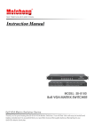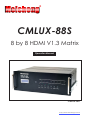
1
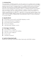
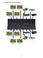
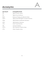
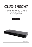
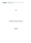
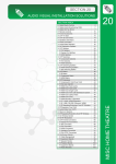
Meicheng R CMLUX-88S 8 by 8 HDMI V1.3 Matrix Operation Manual CMLUX-88S http://www.meicheng.com.tw Disclaimers The information in this manual has been carefully checked and is believed to be accurate. Meicheng assumes no responsibility for any infringements of patents or other rights of third parties which may result from its use. Meicheng assumes no responsibility for any inaccuracies that may be contained in this document. Meicheng also makes no commitment to update or to keep current the information contained in this document. Meicheng reserves the right to make improvements to this document and/or product at any time and without notice. Copyright Notice No part of this document may be reproduced, transmitted, transcribed, stored in a retrieval system, or any of its part translated into any language or computer file, in any form or by any means - electronic, mechanical, magnetic, optical, chemical, manual, or otherwise - without express written permission and consent from Meicheng. © Copyright 2010 by Meicheng. All Rights Reserved. Version 1.0 March 2010 Trademark Acknowledgments All products or service names mentioned in this document may be trademarks of the companies with which they are associated. Safety Precautions Please read all instructions before attempting to unpack or install or operate this equipment, and before connecting the power supply. Please keep the following in mind as you unpack and install this equipment: Always follow basic safety precautions to reduce the risk of fire, electrical shock and injury to persons. To prevent fire or shock hazard, do not expose the unit to rain, moisture or install this product near water. Never spill liquid of any kind on or into this product. Never push an object of any kind into this product through module openings or empty slots, as you may damage parts. Do not attach the power supply cabling to building surfaces. Do not allow anything to rest on the power cabling or allow it to be abused by persons walking on it. To protect the equipment from overheating, do not block the slots and openings in the module housing that provide ventilation. Table of Contents 1. Introduction ……………………..……………………...…........….……. 1 2. Applications …………………..………………….……...................….. 1 3. Package Contents ………………………...........……….................… 1 4. System Requirements ……………..……….........………............……. 1 5. Features …………………………………………......……........…...…… 2 6. Specifications ………………………………...……..........………....…. 3 7. Operation Controls and Functions ……………...……..............…… 7.1 Front Panel .............................................................................. 4 7.2 Rear Panel .…………………………………..…….......…...….… 6 Remote Control .......................…......……………..........…..…....…... 7 8.1 IR Costom Code.................…......……………..........…..…....…. 7 8.2 Discrete IR codes for 8x8 HDMI matrix (IR3).........…..…....…... 7 IR Pin Assignment ............................................................................. 8 9.1 IR Receiver ............................................................................... 8 RS-232 Protocols ……………...……........……................................… 10.1 Pin Assignment ...................................................................... 8 10.2 Commands ………...……………….………….........……....… 9 11. Connection and Installation ….………………….........…..…..…...... 11 12. Acronyms …...................................................................................... 12 8. 9. 10. 4 8 1. Introduction The popularity of HDMI products over the years is now widely seen in today’s commercial and residential environments. People usually have several HDMI displays and sources in a single place. As multiple HDMI inputs and outputs increase, the need for a HDMI matrix that will inter-connect these HDMI devices is becoming more eminent. HDMI V1.3 Matrix provides this excellent and convenient solution. It also features a variety of choices on where to play the images with an existing remote controller. Further, the HDMI V1.3 Matrix supports HDMI 1.3, HDCP 1.1 and DVI 1.0, and can transfer Deep Color video and bit stream digital audio with maximum performance. Last but not least, the input EDID is independent allowing each input to switch between TV or built-in EDID. 2. Applications Multi-HDMI sources with multi-HDMI displays control Event entertainment integration Multi-task project presentation Showroom display Advertisement display control 3. Package Contents 8 by 8 HDMI V1.3 Matrix Remote Control CR33 with battery 24V DC power adaptor Power cord Operation Manual 4. System Requirements HDMI input device(s) and HDMI output device(s) with HDMI cables. 1 5. Features HDMI 1.3, HDCP 1.1 and DVI 1.0 compliant Supports digital video formats in Deep Color 10 bits and new lossless compressed (Dolby TrueHD, Dolby Digital Plus and DTS HD Master Audio) digital audio The HDMI input is compensated, clock / phase adjusted and jitter eliminated so the output is brand new standard HDMI signal Supports recall, memory and key lock function Compatible with all HDMI sources and displays Supports a wide range of PC and HDTV resolutions from VGA to UXGA and 480i to 1080p Supports RS-232 control and firmware upgrading through USB port Supports IR remote control and IR extender Dolby Digital, DTS digital audio transmission (32-192KHz Fs sample rate) Supports LPCM 7.1 channels output from each independent HDMI ports HDMI cable distance test with 1080p/8 bits & 10bits resolution, the Input/ Output can run up to 10/15 & 10/10 meters Independent switchable EDID function for choosing the native resolution to display High performance HDMI 1.3 Matrix with 8 (eight) inputs and 8 (eight) outputs with remote control for link up HDMI devices to enjoying movies, music or games at once. Supports 38KHz IR extender 4U's rack design for easy installation Useful hot keys for quick set up Slide track with handles for easy store Firm housing structure with intensify placement allowing heat dispensing profoundly 2 6. Specifications Input Ports 8 x HDMI Output Ports 8 x HDMI IR Frequency 20~60KHz Power Supply 24VDC/6.25A (US/EU standards, CE/FCC/UL certified) ESD Protection Human body model: ± 10kV (air-gap discharge) ± 6kV (contact discharge) Dimensions (mm) 482(W) x385(D) x 176(H) Weight(g) 9500 Chassis Material Aluminum Silkscreen Color Metal Black Power Consumption 100W Operating Temperature 0˚C ~ 40˚C / 32˚F ~ 104˚F Storage Temperature -20˚C ~ 60˚C / -4˚F ~ 140˚F Relative Humidity 20~90% RH (no condensation) 3 7. Operation Controls and Functions The following sections describe the hardware components of the unit. 7.1 Front Panel ① ② ③ ④ ⑤ ⑥ ⑦ ⑧ ⑨ ⑩ ① LCM monitor: This monitor displays your setting information with each output and input selection. ② IR sensor. ③ POWER: Press this button to turn on the system. When system is ON the LED will illuminate in GREEN. Press it again to enter into STANDBY mode, the LED will illuminate in RED. ④ EDID: Press this button to select the EDID function from the LCM. There will be two selection available shown in LCM; 1. TV Mode and 2. Standard Mode, press the number key to select the desire input first then press 1 or 2 to select the EDID mode. The LED will illuminate while setting the EDID. After the selection is made, press enter key to confirm. Standard mode means the device will use internal built-in EDID and TV mode means the device will use TV/display’s EDID. When EDID switched to TV, leave as it is if the displays are properly. Factory default setting is on TV mode. Notes: 1. When EDID switch to TV the device will detect the first HDMI output source’sEDID from A~D and record in t he unit regardless of the HDMI output source from E~H. If the first detected output source is DVI it will pass to next source,until the first HDMI is detected. The detection priority is HDMI v1.3 > HDMI v1.2 > DVI. Therefore, to ensure all output displayable outpt E~H must obtain lower standard than output A~D. 2. When EDID is on STD, the device will use the built-in EDID Video Supports < 1080p 10 bits (max) Audio Supports = PCM2 4 ⑤ LOCK: Press this button to lock all functions and press it again to release the lock function. When LED illuminate in GREED, lock function is activate. If the LED is not illuminate, the key lock is released. ⑥ ENTER: Press this button after each and every selection to confirm the setting. If this button is not pressed after 20 second of the selection, the selection will be avoid. ⑦ ALL: Press this button to set all the outputs to display with the same input. After press this All button press an input number and press enter to confirm the selection. ⑧ MEMORY: Press this button to set your desire setting total of 6 sets. Press the desire setting number first. When all the input/output are being set, press MEMORY to record into the system and there are 6 settings can record into the system. Factory default setting is 1.12345678, 2.87654321, 3.11223344, 4.55667788, 5.11221122, 6.33443344. ⑨ RECALL: Press this button to recall the previous setting from memory total of 6 sets, and select from 1~6 for the desire setting. Press enter button to confirm the selection. ⑩ OUT A~H & IN 1~8: Press the output sources selection to correspond the input ports. Press first your output selection from A~H and wait for 2 sec. and press again the input selection from 1~8 then press the enter button to confirm your setting. Each output selection only allows a single input setting each time. 5 7.2 Rear Panel ① ② ③ ④ ⑤ ⑥ ⑦ ① HDMI OUTPUT A~H: These slots are where you connect to the HDMI displays. ② SERVICE: This slot is where you connect with a D-Sub 9 pin male connector cable to your host side for firmware upgrading. ③ RS-232: This slot is where you connect with a D-Sub 9 pin female connector cable to your host side for controlling 8 by 8 HDMI Matrix. ④ USB SERVICE: This slot is where you connect with a USB B type connector cable to your host side for ISP (System Program) firmware burning CS8957 total of 4. ⑤ IR IN: This slot is where you can extend your IR receiver with IR extender cable that accepts only 38KHz. ⑥ HDMI INPUT 1~8: These slots are where you connect the HDMI or DVI output of your source equipments such as DVD player or set-top-box. ⑦ DC 24V: Plug the 24V DC power supply into the unit and connect the adaptor to AC wall outlet. 6 8. Remote Control This remote control can be set with multiple format according to the dipswitch setting. There are total of four dipswitches with mainly two kinds of settings. When dipswitches are all set to ON/↑ the remote control is able to control all outputs and all inputs. For example, when output A wish to select input 5. Press 1 first and wait for a second then press 5, the output display A will display input source 5’s image instantly. Other settings referring to below section 8.2 section 8.2 are output based to control input selections. For example, when all dipswitches are set to OFF/↓ this setting is base on output A and therefore, it can only control inputs selection. Hence, when output A wish to selelct input 3 press 3 only will switch output display A to display input source 3’s contents. Further setting please refers to section 8.2. 1 2 3 4 5 6 8 9 7 0 CR-71 8.1 IR Costom Code NO. 1 2 3 4 5 6 7 8 9 0 DATA 88 89 8A 8C 8D 8E 90 91 92 95 8.2 Discrete IR codes for 8x8 HDMI matrix (IR3) Select / Dipswitch output A ↓↓↓↓ input 1 0cx88 input 2 0x89 input 3 0x8A input 4 0x8C input 5 0x8D input 6 0x8E input 7 0x90 input 8 0x91 output B ↑↓↓↓ 0x88 0x89 0x8A 0x8C 0x8D 0x8E 0x90 0x91 output C ↓↑↓↓ 0x88 0x89 0x8A 0x8C 0x8D 0x8E 0x90 0x91 output D ↑↑↓↓ 0x88 0x89 0x8A 0x8C 0x8D 0x8E 0x90 0x91 output E ↓↓↑↓ 0x88 0x89 0x8A 0x8C 0x8D 0x8E 0x90 0x91 output F ↑↓↑↓ 0x88 0x89 0x8A 0x8C 0x8D 0x8E 0x90 0x91 output G ↓↑↑↓ 0x88 0x89 0x8A 0x8C 0x8D 0x8E 0x90 0x91 output H ↑↑↑↓ 0x88 0x89 0x8A 0x8C 0x8D 0x8E 0x90 0x91 7 9. IR Pin Assignment 9.1 IR Receiver ① IR signal ② Power 5V ③ Grounding ① ②③ 10. RS-232 Protocols 10.1 Pin Assignment CMLUX-88S Remote Control Console PIN Assignment PIN Assignment 1 NC 1 NC 2 Tx 2 Rx 3 Rx 3 Tx 4 NC 4 NC 5 GND 5 GND 6 NC 6 NC 7 NC 7 NC 8 NC 8 NC 9 NC 9 NC Baud Rate: 19200bps Data bit: 8 bits Parity: None Flow Control: None 8 10.2 Commands COMMAND ACTION POWER 00 Power Off (standby) POWER 01 Power On PORT 11 Output A select Input1 PORT 12 Output A select Input2 PORT 13 Output A select Input3 PORT 14 Output A select Input4 PORT 15 Output A select Input5 PORT 16 Output A select Input6 PORT 17 Output A select Input7 PORT 18 Output A select Input8 PORT 21 Output B select Input1 PORT 22 Output B select Input2 PORT 23 Output B select Input3 PORT 24 Output B select Input4 PORT 25 Output B select Input5 PORT 26 Output B select Input6 PORT 27 Output B select Input7 PORT 28 Output B select Input8 PORT 31 Output C select Input1 PORT 32 Output C select Input2 PORT 33 Output C select Input3 PORT 34 Output C select Input4 PORT 35 Output C select Input5 PORT 36 Output C select Input6 PORT 37 Output C select Input7 PORT 38 Output C select Input8 PORT 41 Output D select Input1 PORT 42 Output D select Input2 PORT 43 Output D select Input3 PORT 44 Output D select Input4 PORT 45 Output D select Input5 PORT 46 Output D select Input6 9 PORT 47 Output D select Input7 PORT 48 Output D select Input8 PORT 51 Output E select Input1 PORT 52 Output E select Input2 PORT 53 Output E select Input3 PORT 54 Output E select Input4 PORT 55 Output E select Input5 PORT 56 Output E select Input6 PORT 57 Output E select Input7 PORT 58 Output E select Input8 PORT 61 Output F select Input1 PORT 62 Output F select Input2 PORT 63 Output F select Input3 PORT 64 Output F select Input4 PORT 65 Output F select Input5 PORT 66 Output F select Input6 PORT 67 Output F select Input7 PORT 68 Output F select Input8 PORT 71 Output G select Input1 PORT 72 Output G select Input2 PORT 73 Output G select Input3 PORT 74 Output G select Input4 PORT 75 Output G select Input5 PORT 76 Output G select Input6 PORT 77 Output G select Input7 PORT 78 Output G select Input8 PORT 81 Output H select Input1 PORT 82 Output H select Input2 PORT 83 Output H select Input3 PORT 84 Output H select Input4 PORT 85 Output H select Input5 PORT 86 Output H select Input6 PORT 87 Output H select Input7 PORT 88 Output H select Input8 10 11. Connection and Installation HD TV HD TV STB HD TV DVD Blu-ray HD TV PS3 Blu-ray HD TV PS3 HD TV STB HD TV HD TV 11 DVD A Acronyms Acronym Complete Term DTS Digital Theater System DVI Digital Visual Interface EDID Extedned Display Identification Data HDCP High-bandwidth Digital Content Protection HDMI High-Definition Multimedia Interface HDTV High-Definition Television LCM Liquid Crystal Monitor USB Universal Serial Bus UXGA Ultra Extended Graphics Array VGA Video Graphics Array 12 Meicheng R MEI CHENG AUDIO VIDEO CO., LTD Address:13F, No. 2, Jian 8th Rd., Jhonghe City, Taipei County 23511, TAIWAN Te l : + 8 8 6 ( 2 ) 8 2 2 8 0 3 1 1 , Fax : + 886(2) 8228 0319 Website : www.meicheng.com.tw Email : [email protected]