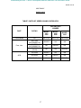
1
efesotomasyon.com - Control Techniques,emerson,saftronics -ac drive-servo motor
Series 2230 MKII
Single-Phase
Adjustable-Speed
Regenerative
DC Motor Controllers
(1/6 – 5 HP)
Control Techniques
3750 East Market Street
York, PA 17402-2798
717-751-4200, FAX 717-751-4263
www.fincor.net
BOOK 0960-B
efesotomasyon.com - Control Techniques,emerson,saftronics -ac drive-servo motor
efesotomasyon.com - Control Techniques,emerson,saftronics -ac drive-servo motor
BOOK 0960-B
SERIES 2230 MKII
SINGLE-PHASE
ADJUSTABLE-SPEED
REGENERATIVE
DC MOTOR CONTROLLERS
(1/6 - 5 HP)
Control Techniques
York Drive Center
3750 E Market Street
York, PA 17402-2798
USA
Tel 717.751.4200
Fax 717.751.4263
www.fincor.net
efesotomasyon.com - Control Techniques,emerson,saftronics -ac drive-servo motor
BOOK 0960-B
efesotomasyon.com - Control Techniques,emerson,saftronics -ac drive-servo motor
BOOK 0960-B
TABLE OF CONTENTS
SECTION
TITLE
PAGE
I .......................................... GENERAL INFORMATION ...................................................................1
Introduction ...............................................................................................1
General Description...................................................................................1
Motor Selection .........................................................................................1
Description of Operation ...........................................................................1
Model Types..............................................................................................2
II.......................................... INSTALLATION......................................................................................3
Installation Guidelines...............................................................................3
Installing the Controller ............................................................................5
Initial Startup...........................................................................................16
III ......................................... OPERATION ..........................................................................................17
Power On/Off ..........................................................................................17
Run ..........................................................................................................17
Stop .........................................................................................................17
Controlled Stop .......................................................................................17
Zero Speed Detection ..............................................................................17
Speed Control..........................................................................................18
Torque Control ........................................................................................18
Jog ...........................................................................................................19
Reverse ....................................................................................................19
Armature Voltage and Current Outputs ..................................................19
Load Monitor (Motor Timed Overload)..................................................20
Direction Output......................................................................................20
Speed Regulator Input.............................................................................20
Inoperative Motor....................................................................................20
IV ......................................... MAINTENANCE AND REPAIR...........................................................21
General ....................................................................................................21
Adjustment Instructions ..........................................................................21
Troubleshooting Instructions...................................................................23
V.......................................... PARTS LIST ...........................................................................................27
VI ......................................... RATINGS AND SPECIFICATIONS .....................................................29
Ratings.....................................................................................................29
Operating Conditions ..............................................................................30
Performance Characteristics....................................................................31
Adjustments.............................................................................................31
Specifications ..........................................................................................31
VII ........................................ DRAWINGS ...........................................................................................33
INDEX ....................................................................................................36
iii
efesotomasyon.com - Control Techniques,emerson,saftronics -ac drive-servo motor
BOOK 0960-B
LIST OF TABLES
TABLE
TITLE
PAGE
1................... Series 2230 MKII Model Matrix...........................................................................................2
2................... Jumper J4 Position........................................................................................................................5
3.................... Dip Switch (SW3) ........................................................................................................................6
4.................... Initial Potentiometer Settings .....................................................................................................16
5.................... Dynamic Braking Characteristics ..............................................................................................18
6.................... Troubleshooting.................................................................................................................... 23-26
7.................... Parts List, Series 2230 MKII Controllers ..................................................................................27
8.................... Typical Application Data ...........................................................................................................29
9.................... Operating Voltages and Signals.................................................................................................30
10................... Controller Weights .....................................................................................................................30
11................... Speed Regulation Characteristics...............................................................................................31
12................... Shunt Field Data .........................................................................................................................32
13................... Tachometer Feedback Voltage Selection ..................................................................................22
LIST OF ILLUSTRATIONS
FIGURE
TITLE
PAGE
1................... Controller Mounting Configurations .....................................................................................7
2................... Controller Mounting Dimensions ................................................................................................8
3.................... Logic Connection Diagram, Run-Stop-Jog Switch.....................................................................9
4.................... Logic Connection Diagram, Forward-Reverse Switch and Run-Stop-Jog Switch ....................9
5.................... Logic Connection Diagram, Run-Stop-Controlled Stop Pushbuttons and Run-Jog Switch....10
6.................... Logic Connection Diagram, Run-Stop-Controlled Stop Pushbuttons and Forward /
Reverse Switch . .........................................................................................................................10
7.................... Logic Connection Diagram, Optional Contactor Using Run-Stop-Jog Switch........................11
8.................... Logic Connection Diagram, Optional Contactor Using Run-Stop Pushbuttons and ...............11
Run-Jog Switch
9.................... Logic Connection Diagram, Line Starting With Motor Speed Potentiometer .........................12
10................... Signal Connection Diagram, Motor Speed Potentiometer, Unidirectional ..............................12
11................... Signal Connection Diagram, Motor Speed Potentiometer, Bidirectional.................................13
12................... Signal Connection Diagram, Tachometer Feedback.................................................................13
13................... Signal Connection Diagram, External Current (Torque) Reference Potentiometer.................13
14................... Signal Connection Diagram, External Current Limit Potentiometers ......................................14
15................... Signal Connection Diagram, Line Starting Without a Motor Speed Potentiometer ................14
16................... Signal Connection Diagram, External PID Controller with Auto/Manual Switch ..................14
17................... Signal Connection Diagram, 4-20mA Outputs – Armature Amps and Volts..........................15
18................... Signal Connection Diagram, 0-±10Vdc Outputs – Armature Amps and Volts .......................15
19................... Functional Schematic, Series 2230 MKII..................................................................................34
20................... Series 2230 MKII Control Board, 1/6 – 3HP ............................................................................35
21................... 2233 MKII Connection Terminals - 5HP..................................................................................36
iv
efesotomasyon.com - Control Techniques,emerson,saftronics -ac drive-servo motor
BOOK 0960-B
Blank Page
v
efesotomasyon.com - Control Techniques,emerson,saftronics -ac drive-servo motor
BOOK 0960-B
WARNING
The following must be strictly adhered to at all times.
1. YOU AS THE OWNER OR OPERATOR OF FINCOR EQUIPMENT HAVE THE RESPONSIBILITY
TO HAVE THE USERS OF THIS EQUIPMENT TRAINED IN ITS OPERATIONS AND WARNED OF ANY
POTENTIAL HAZARDS OF SERIOUS INJURY.
2. THE DRIVE EQUIPMENT SHOULD BE INSTALLED, OPERATED, ADJUSTED, AND SERVICED
ONLY BY QUALIFIED PERSONNEL FAMILIAR WITH THE CONSTRUCTION AND OPERATION
OF THE EQUIPMENT AND THE HAZARDS INVOLVED INCLUDING THOSE DESCRIBED
BELOW. FAILURE TO OBSERVE THIS WARNING CAN RESULT IN PERSONAL INJURY, LOSS OF LIFE,
AND PROPERTY DAMAGE.
3. THE NATIONAL ELECTRICAL CODE REQUIRES THAT AN AC LINE FUSED DISCONNECT OR
CIRCUIT BREAKER BE PROVIDED IN THE AC INPUT POWER LINES TO THE CONTROLLER. THIS
DISCONNECT MUST BE LOCATED WITHIN SIGHT OF THE CONTROLLER. DO NOT OPERATE
THE CONTROLLER UNTIL THIS CODE REQUIREMENT HAS BEEN MET.
4. THE DRIVE EQUIPMENT IS AT AC LINE VOLTAGE WHENEVER AC POWER IS CONNECTED TO
THE DRIVE EQUIPMENT. CONTACT WITH AN ELECTRICAL CONDUCTOR INSIDE THE DRIVE
EQUIPMENT OR AC LINE DISCONNECT CAN CAUSE ELECTRIC SHOCK RESULTING IN
PERSONAL INJURY OR LOSS OF LIFE.
5. BE SURE ALL AC POWER IS DISCONNECTED FROM THE DRIVE EQUIPMENT BEFORE
TOUCHING ANY COMPONENT, WIRING, TERMINAL, OR ELECTRICAL CONNECTION IN THE
DRIVE EQUIPMENT.
6. ALWAYS WEAR SAFETY GLASSES WHEN WORKING ON THE DRIVE EQUIPMENT.
7. DO NOT REMOVE OR INSERT CIRCUIT BOARDS, WIRES, OR CABLES WHILE AC POWER IS
APPLIED TO THE DRIVE EQUIPMENT. FAILURE TO OBSERVE THIS WARNING CAN CAUSE
DRIVE DAMAGE AND / OR PERSONAL INJURY.
8. ALL DRIVE EQUIPMENT ENCLOSURES, MOTOR FRAMES, AND REMOTE OPERATOR
STATIONS MUST BE CONNECTED TO AN UNBROKEN COMMON GROUND CONDUCTOR. AN
UNBROKEN GROUNDING CONDUCTOR MUST BE RUN FROM THE COMMON GROUND
CONDUCTOR TO A GROUNDING ELECTRODE BURIED IN THE EARTH OR ATTACHED TO A
PLANT GROUND. REFER TO THE NATIONAL ELECTRICAL CODE AND LOCAL CODES FOR
GROUNDING REQUIREMENTS.
9. THE ATMOSPHERE SURROUNDING THE DRIVE EQUIPMENT MUST BE FREE OF COMBUSTIVE
VAPORS, CHEMICAL FUMES, OIL VAPOR, AND ELECTRICALLY CONDUCTIVE OR CORROSIVE
MATERIALS.
10. SOLID-STATE DEVICES IN THE CONTROLLER CAN BE DESTROYED OR DAMAGED BY
STATIC ELECTRICITY. THEREFORE, PERSONNEL WORKING NEAR THESE STATICSENSITIVE
DEVICES MUST BE APPROPRIATELY GROUNDED.
vi
efesotomasyon.com - Control Techniques,emerson,saftronics -ac drive-servo motor
BOOK 0960-B
SECTION I
GENERAL INFORMATION
INTRODUCTION
This manual contains installation, operation, and maintenance and repair instructions for Fincor Series 2230 MKII
Single-Phase Adjustable-Speed Regenerative DC Motor Controllers. A parts list, ratings and specifications, and
drawings are also included.
GENERAL DESCRIPTION
Series 2230 MKII Controllers statically convert AC line power to regulated DC for adjustable-speed armature
control of shunt-wound and permanent-magnet motors.
Applications include those requiring controllable bi-directional torque for overhauling loads, contactor-less
reversing, and position control.
Series 2230 MKII Controllers comply with applicable standards established by the National Electrical Code and
NEMA for motor and industrial control equipment. The controllers are Underwriters Laboratories Listed (File No.
E184521) UL/cUL.
MOTOR SELECTION
Series 2230 MKII Controllers control the operation of general purpose DC motors designed for use with solid-state
rectified power supplies. The motor may be shunt-wound, stabilized shunt-wound, or permanent magnet. For
maximum efficiency, the motor should be rated for operation from a NEMA Code K power supply.
DESCRIPTION OF OPERATION
Series 2230 MKII Regenerative Controllers, also known as four-quadrant controllers, not only control motor
speed and direction of rotation, but also the direction of motor torque.
Referring to Figure 1, when the drive (controller and motor) is operating in Quadrants I and III, motor rotation
and torque are in the same direction and the drive functions as a conventional non-regenerative drive. In
Quadrants II and IV, motor torque opposes the direction of motor rotation, which results in controlled braking.
The drive can switch rapidly from motoring to braking modes while simultaneously controlling the direction of
motor rotation. Under braking conditions, the controllers convert the mechanical energy of the motor and
connected load into electrical energy, which is returned (regenerated) to the AC power source.
FIGURE 1. Four-Quadrant Operation
1
efesotomasyon.com - Control Techniques,emerson,saftronics -ac drive-servo motor
BOOK 0960-B
MODEL TYPES
TABLE 1. SERIES 2230 MKII MODEL MATRIX
a
FUNCTION
CONFIGURATION
OPERATOR CONTROLS
POWER SOURCE &
HP RANGE
MODEL
RUN/STOP
JOG
b
SWITCH
ARMATURE
CONTACT
c
AND DB
2231
OPEN
CHASSIS
X
X
X
X
X
X
2232
2232B
X
2236
2236B
X
2233
2233B
X
2233P0
2233P1
a.
b.
c.
X
X
X
X
1/6 -1
1/3 - 2
1/6 - 1
1/3 - 3
1/2 - 2
1-5
X
X
X
X
X
X
X
X
X
X
X
X
X
X
X
X
X
2233BP0
2233BP1
X
X
2235B
230V
X
X
X
2235
115V
X
X
2231BP0
REMOTE
X
X
2231P0
2231BP1
LOCAL
INTEGRAL
X
2231B
2231P1
ENCLOSED
X
X
X
X
X
Units are reconnectable
No armature contactor
Includes armature contactor
2
X
X
X
X
efesotomasyon.com - Control Techniques,emerson,saftronics -ac drive-servo motor
BOOK 0960-B
SECTION II
INSTALLATION
Before starting the installation, read this section thoroughly. In addition, a thorough review of the Ratings and
Specifications (Section VI) is recommended. The following installation guidelines should be kept in mind when
installing the controller.
INSTALLATION GUIDELINES
1. CONTROLLER MOUNTING - The controller may be mounted either vertically or horizontally. However, never
mount the controller upside down, immediately beside or above heat generating equipment, or directly below water or
steam pipes.
The controller must be mounted in a location free of vibration.
Multiple controllers may be mounted side by side, as close to each other as the mounting feet will allow.
The minimum clearance at the top and bottom of the controller may be as narrow as the conduit fittings allow.
2. ATMOSPHERE - The atmosphere surrounding the controller must be free of combustible vapors, chemical fumes,
oil vapor, and electrically conductive or corrosive materials.
The air surrounding an enclosed controller must not exceed 40 degrees C (104 degrees F), and the air surrounding an
open-chassis controller must not exceed 55 degrees C (131 degrees F). Minimum air temperature is 0 degree C (32
degrees F) for enclosed and open-chassis controllers.
3. CONTROLLER CONSTRUCTION - Enclosed controllers are totally enclosed, non-ventilated, and comply with
NEMA Type 4 and 12 standards. There is an oil resistant synthetic rubber gasket between the cover and base. Those
models with integral operator controls include flexible boots to seal the switches, and a seal for the MOTOR SPEED
potentiometer.
Model 2235MKII and 2236MKII controllers are unenclosed open-chassis units with the printed wiring board mounted on
an aluminum bracket.
The small controller base is made of die-cast aluminum with a powdered epoxy finish, and the cover is made of a diecast aluminum alloy. The larger controller base is made of extruded aluminum and the cover is made of Noryl®, a
strong engineering plastic with outstanding mechanical, thermal, and electrical properties.
4. LINE SUPPLY - The controller should not be connected to a line supply capable of supplying more than 5,000
amperes short-circuit current. Short-circuit current can be limited by using an input supply transformer of 50 KVA or
less, or by using correctly sized current limiting fuses in the supply line ahead of the controller. Do not use a
transformer with less than the minimum transformer KVA listed in Table 8, page 29.
If rated line voltage is not available, a line transformer will be required. If the line supply comes directly from a
transformer, place a circuit breaker or disconnect switch between the transformer secondary and the controller. If power
is switched in the transformer primary, transients may be generated which can damage the controller. See Table 8 (page
29) for minimum transformer KVA.
Do not use power factor correction capacitors on the supply line to the controller.
A 20 Joule metal oxide varistor (MOV) is connected across the controller terminals. If higher energy transients are
present on the line supply, additional transient suppression will be required to limit transients to 150% of peak line
voltage.
3
efesotomasyon.com - Control Techniques,emerson,saftronics -ac drive-servo motor
BOOK 0960-B
When a 115 VAC line supply is used, connect the white (common) wire to Terminal L2 and connect the remaining
(hot) wire to Terminal L1.
5. ISOLATION TRANSFORMER - While not required, an isolation transformer can provide the following
advantages:
a. Reduce the risk of personal injury if high voltage drive circuits are accidentally touched.
b. Provide a barrier to externally generated AC supply transients. This can prevent controller damage from abnormal
line occurrences.
c. Reduce the potential for damaging current if the motor armature, motor field, or motor wiring becomes grounded.
6. GROUNDING - Connect the green or bare (ground) wire of the line supply to the ground screw located near the top
conduit entry hole in the controller base. Then ground the controller base by connecting the ground screw to earth
ground.
The motor frame and operator control stations must also be grounded.
Personal injury may occur if the controller, motor, and operator stations are not properly grounded.
7. WIRING PRACTICES - The power wiring must be sized to comply with the National Electrical Code, CSA, or
local codes. Refer to the controller data label for line and motor current ratings.
Do not use solid wire.
Signal wiring refers to wiring for potentiometers, tachometer generators, and transducers. Control wiring refers to
wiring for operator controls, e.g., switches and pushbuttons. Signal and control wiring may be run in a common
conduit, but not in the same conduit as the power wiring. In an enclosure, signal and control wiring must be kept
separated from power wiring and only cross at a 90 degree angle to reduce electrical noise.
If shielded wire (such as Alpha 2422 - two conductor, 2423 - three conductor, 2424 - four conductor) is used for the
signal and control wiring, connect the shields to chassis ground (ground screw on the controller base) and tape the
opposite ends of the shields. Twisted cable is also suitable for signal and control wiring.
The small base models provide two 3/4-14 NPT threaded holes for conduit entry, one each in the top and bottom of the
controller.
The large base models provide two 3/4 inch conduit entry for the power in and out wiring, and one 1/2 inch conduit
entry for signal wiring.
4
efesotomasyon.com - Control Techniques,emerson,saftronics -ac drive-servo motor
BOOK 0960-B
INSTALLING THE CONTROLLER
1. Remove the controller front cover (if used) by removing the four cover screws.
2. Check components in the controller for shipping damage. Report shipping damage to the carrier.
3. Check the controller and motor data labels to be sure the units are electrically compatible.
4. Be sure the controller has been calibrated correctly for the motor being used. The initial calibration is performed
by changing the position of a Jumper J4 on the controller control board to comply with Table 2. To change the
position of Jumper J4, pull the jumper from the control board and then push it onto the appropriate two pins on the
board. Select the position closest, but not less then, the motor nameplate armature current rating. The final calibration can be
fined tuned, if needed, by the current limit potentiometer. For the location of J4 and the current limit potentiometer, see
Figure 20 (page 35).
TABLE 2. JUMPER J4 POSITION
MOTOR ARMATURE CURRENT RATING (AMPERES)
JUMPER
a
POSITION
100%
80%
60%
40%
20%
2231 - 2235
2 HP Maximum
2232 - 2236
3 HP Maximum
2233
5 HP Maximum
10
8
6
4
2
15
12
9
6
3
25
20
15
10
5
5. Check the positions of Jumpers J1, J2, and J3 on the control board. For the locations of J1, J2, and J3, see Figure 20,
page 35. For a 230 VAC line supply and a 180V armature motor, Jumper J1 must be in the 230V position, and Jumpers
J2 and J3 must be in the 180V position. For a 115 VAC line supply and a 90V armature motor, J1 must be in the
115V position, and J2 and J3 must be in the 90V position. To change the position of J1, J2, or J3 pull the jumper
from the control board and then push it onto the appropriate pins on the board.
NOTE: If Option 1001 (Armature Contactor), or 1775 (Signal Interface) is to be installed in the controller, do not offset
the five-position plug (supplied with the option) at Connector J1 on the control board. Do not confuse Connector J1 with
Jumper J1. Refer to the Instruction Sheet (ISP0703, ISP0653, respectively) supplied with the option for connection
instructions.
6. If the controller is to operate from a 50 Hz supply, set segment 6 of the DIP Switch (SW3) to the “OFF”
position on the controller control board. For the location of DIP Switch SW3, see Figure 20, page 35.
7. The controller may be surface mounted or panel mounted as shown in Figure 1, page 7. Mount the controller.
Mounting dimensions are shown in Figure 2, page 8.
8. Conduit entry is made by punching out the knockout at the top or bottom of the controller base. To prevent
component damage from knockout fragments, apply masking tape to the inside of the knockout before punching.
9. Connect the power wiring to Terminals L1, L2, A1, A2, F+ and F-. Be sure to observe Installation Guidelines 4 and
7 on pages 3 and 4. If half-wave shunt field voltage is desired, connect one of the motor shunt field leads to
Terminal L1 (see Table 12 on page 32).
Note:
Low inductance motors require a full-wave field to prevent current instability.
5
efesotomasyon.com - Control Techniques,emerson,saftronics -ac drive-servo motor
BOOK 0960-B
10. If the controller contains any options that require external wiring, follow the wiring instructions in the instruction
sheet supplied with the option.
11. If remote operator control wiring and/or signal wiring is required, connect the controller as shown in the appropriate
connection diagram (Figures 3 through 18). Figures 3 through 9 show operator control connections, and Figures 10
through 18 show signal connections.
12. The controller can be programmed for various applications by throwing switches on dip switch SW3
TABLE 3. DIP SWITCH (SW3)
FACTORY DEFAULT SETTING IS UNDERLINED
Switch Position
ON
Selects anti-restart mode. Prevents controller from restarting automatically after an AC line
power interruption.
OFF
Disables anti-restart mode. Used for line starting applications (jumper TB2:9 to TB2:8 to
enable drive).
ON
Selects internal Forward current (torque) reference pot.
OFF
Selects use of an external Forward current (torque) reference pot.
(Set internal Forward current limit pot at 100%)
ON
Adds ≈2% zero speed reference deadband to prevent motor creeping.
OFF
No zero speed deadband; enabled drive may creep with zero speed reference
ON
Selects torque regulator mode.
OFF
Selects speed regulator mode.
ON
Low voltage (3Vdc - 30Vdc) tachometer scaling
OFF
High voltage (31 Vdc - 175Vdc) tachometer scaling.
ON
Selects 60Hz line input frequency.
OFF
Selects 50Hz line input frequency.
1
2
3
4
5
6
7
ON
OFF
Selects internal Reverse current (torque) reference pot.
Selects use of an external Reverse current (torque) reference pot.
(Set internal Reverse current limit pot at 100%)
13. Install the controller cover, if used.
6
efesotomasyon.com - Control Techniques,emerson,saftronics -ac drive-servo motor
BOOK 0960-B
FIGURE 1. CONTROLLER MOUNTING CONFIGURATIONS
BR1 - FWD
G3
G1
G4
G2
G3
G1
G4
G2
BR2 - REV
2233 DRIVE
FIGURE 2. CONTROLLER MOUNTING DIMENSIONS
7
efesotomasyon.com - Control Techniques,emerson,saftronics -ac drive-servo motor
BOOK 0960-B
FIGURE 2. CONTROLLER MOUNTING DIMENSIONS
8
efesotomasyon.com - Control Techniques,emerson,saftronics -ac drive-servo motor
BOOK 0960-B
Figure 3. Logic connection diagram, Run-Stop-Jog Switch
Figure 4. Logic connection diagram, Forward-Reverse Switch and Run-Stop-Jog Switch
9
efesotomasyon.com - Control Techniques,emerson,saftronics -ac drive-servo motor
BOOK 0960-B
Figure 5. Logic connection diagram, Run-Stop Controlled Stop Pushbuttons and
Run-Jog Switch
Figure 6. Logic connection diagram, Run-Stop-Controlled Stop Pushbuttons,
Run-Jog Switch and Forward-Reverse Switch
10
efesotomasyon.com - Control Techniques,emerson,saftronics -ac drive-servo motor
BOOK 0960-B
Figure 7. Logic connection diagram, Optional Contactor using Run-Stop-Jog Switch
Figure 8. Logic connection diagram, Optional Contactor using Run-Stop Pushbuttons and
Run-Jog Switch
11
efesotomasyon.com - Control Techniques,emerson,saftronics -ac drive-servo motor
BOOK 0960-B
Figure 9. Logic connection diagram, Line Starting with Motor Speed Potentiometer
Figure 10. Signal Connection Diagram, Motor Speed Potentiometer, Unidirectional
12
efesotomasyon.com - Control Techniques,emerson,saftronics -ac drive-servo motor
BOOK 0960-B
Figure 11. Signal Connection Diagram, Motor Speed Potentiometer, Bidirectional
Figure 12. Signal Connection Diagram, Tachometer Feedback
Figure 13. Signal Connection Diagram, External Current (Torque) Reference Potentiometer
13
efesotomasyon.com - Control Techniques,emerson,saftronics -ac drive-servo motor
BOOK 0960-B
Figure 14. Signal Connection Diagram, External Current Limit Potentiometers
Figure 15. Signal Connection Diagram, Line Starting Without a Motor Speed Potentiometer
Figure 16. Signal Connection Diagram, External PID Controller input with Auto/Manual Switch
14
efesotomasyon.com - Control Techniques,emerson,saftronics -ac drive-servo motor
BOOK 0960-B
Figure 17. Signal Connection Diagram, 4-20mA Outputs – Armature Amps and Volts
Figure 18. Signal Connection Diagram, 0 to ±10V Outputs – Armature Amps and Volts
15
efesotomasyon.com - Control Techniques,emerson,saftronics -ac drive-servo motor
BOOK 0960-B
INITIAL STARTUP
1. Open the controller cover (if used) by removing the four cover screws.
2. Be familiar with all options installed in the controller by reviewing the instruction sheets supplied with the options.
3. Be sure all wiring is correct and all wiring terminations are tightened securely.
4. Be sure the controller is calibrated correctly. See steps 4 and 5 under “Installing the Controller” on page 5. Be sure
the AC supply voltage to the controller agrees with the controller data label.
6. The potentiometers in the controller are factory adjusted as shown in Table 4. These settings will provide satisfactory
operation for most applications. If different settings are required, refer to “Adjustment Instructions” starting on page 21
.
TABLE 4. INITIAL POTENTIOMETER SETTINGS
POTENTIOMETER
SETTING
DESCRIPTION
ACCEL
1/3 Turn Clockwise
10 Seconds
DECEL
1/3 Turn Clockwise
10 Seconds
IR/TACH
Fully Counterclockwise (0%)
0% Boost
MAX SPD
3/4 Turn Clockwise
100% Speed
FWD CUR LMT
Fully Clockwise (100%)
150% Load
REV CUR LMT
Fully Clockwise (100%)
150% Load
SPD STAB
1/2 Turn Clockwise
Nominal Gain
FWD CUR STAB
1/2 Turn Clockwise
Nominal Gain
REV CUR STAB
1/2 Turn Clockwise
Nominal Gain
7. If the controller has a cover, place it on the controller and secure it with the four cover screws.
8. Turn-on the AC supply to the controller.
9. Check motor rotation, as follows:
a. If a MOTOR SPEED potentiometer is used, turn it to zero on its dial. If an external signal is used for the
speed reference, set it at minimum.
b. If a RUN-STOP-JOG switch is used, place it in RUN position. Otherwise, initiate a Run command.
c. Turn the MOTOR SPEED potentiometer clockwise or increase the speed reference signal, as applicable. To stop
the motor, place the switch in STOP position or initiate a Stop command, as applicable.
If the motor rotates in the wrong direction, turn-off the AC supply to the controller, and then interchange the motor
armature leads at the motor connection box or at the controller terminal board.
10. Refer to Section III, “Operation” for operating instructions on page 17.
16
efesotomasyon.com - Control Techniques,emerson,saftronics -ac drive-servo motor
BOOK 0960-B
SECTION III
OPERATION
POWER ON/OFF
To energize the drive, turn-on the AC supply voltage to the controller. When this occurs, the motor shunt field
energizes with rated field voltage, and potentially hazardous voltage is present at the motor armature terminals. These
voltages can cause electric shock resulting in personal injury or loss of life.
If the AC supply is interrupted, and the controller is not set up for line starting, the motor will not restart when the
AC supply is restored until the controller is reset by initiating a Stop command and then a Start command. If the
controller is set up for line starting, and the AC supply is interrupted, the motor will restart when the AC supply is
restored, provided the external AC line contactor is pulled in.
RUN
If a RUN-STOP-JOG switch is used, place the switch in RUN position. Otherwise, initiate a Run command. A Run
command will accelerate the motor to the setting of the MOTOR SPEED potentiometer or external speed reference
signal, as applicable. The rate of acceleration is preset by the ACCEL potentiometer on the controller control board.
STOP
If a RUN-STOP-JOG switch is used, place the switch in STOP position. Otherwise, initiate a Stop command. A Stop
command will stop the motor at a rate proportional to the stopping rate of the motor load.
If the controller has dynamic braking, the motor stopping time will be reduced. Dynamic braking provides exponential
rate braking of the motor armature, which occurs when the circuit is opened between the controller and the motor
armature, and one or more resistors connect across the motor armature.
The dynamic braking resistors provide initial braking torque and stops per minute as shown in Table 5.
CONTROLLED STOP
Controlled stop is designed to be used with pushbutton (momentary) control, and should always include an
emergency stop (coast) pushbutton to guarantee removal of the +24V control voltage from the enable input
(TB2:8). When a controlled stop is initiated by momentarily applying +24V to TB2:12 input, the drive will
decelerate the motor from set speed to zero speed at the Decel pot setting rate, and then drop out run relay K0 at
zero speed (≈2% or less), determined by armature voltage. Note that if an overhauling load continues to rotate the
motor above ≈2% speed, the zero speed detection circuit will not drop out K0.
ZERO SPEED DETECTION
The zero speed detection circuit used for controlled stop is also buffered and brought out to TB2:13 for use as an
active low Zero Speed Output function (≈2% or less). The output is rated at 60V and 50ma @100°C, sufficient
for switching 24Vdc loads (although the drive +24V power supply cannot supply this much customer current; it
must be customer supplied).
17
efesotomasyon.com - Control Techniques,emerson,saftronics -ac drive-servo motor
BOOK 0960-B
TABLE 5. DYNAMIC BRAKING CHARACTERISTICS a
COMPONENT
BRAKING TORQUE (%)
STOPS PER MINUTE
a.
MODEL
2231
2235
2232
2233
2231
2235
2232
2233
RATED
VOLTAGE
RATED
HORSEPOWER
1/6
1/4
1/3
1/2
3/4
1
1-1/2
2
3
5
115V
180
129
103
66
44
34
NA
NA
NA
NA
230V
NA
NA
400
278
190
130
88
62
NA
NA
115V
300
215
170
110
75
60
NA
NA
NA
NA
230V
NA
NA
NA
400
320
220
145
105
85
96
115V
15
12
11
8
6
2
NA
NA
NA
NA
230V
NA
NA
12
8
6
1
1
1
NA
NA
115V
9
6
5
5
4
4
NA
NA
NA
NA
230V
NA
NA
NA
5
4
4
3
3
2
2
HIGH INERTIA LOADS MAY EXTEND BRAKING TIME AND CAUSE THE WATTAGE
RATING OF THE DYNAMIC BRAKING RESISTORS TO BE EXCEEDED.
An antiplug feature is included with optional Dynamic Braking. This feature prevents restarting the motor before
the motor has braked to a stop.
SPEED CONTROL
Set Dip Switch SW3 position 4 to “OFF” (factory default). Motor speed is directly proportional to the setting of the
MOTOR SPEED potentiometer or the magnitude of an external speed reference signal, as applicable. This
potentiometer or the speed reference signal may be adjusted while the motor is running or may be preset before the
motor is started.
The rates of acceleration and deceleration are preset by the ACCEL and DECEL potentiometers, respectively,
located on the controller control board.
Maximum speed is preset by the MAX SPD potentiometer, located on the control board.
TORQUE CONTROL
Set Dip Switch SW3 position 4 to “ON”. Motor torque is directly proportional to the setting of the Forward and
Reverse Current Limit potentiometers. A single torque reference input for an external torque signal or an external
torque potentiometer may be set up by setting Dip Switch SW3 positions 2 and 7 to “OFF” and connecting the
external torque signal to TB2 positions 5 and 6, or connecting an External Torque Reference potentiometer as shown
in Figure 13 on page 13 . The internal Forward and Reverse current limit pots should be typically set at 100%, or can be
used to trim the external Torque reference differently for Forward and Reverse torque (note, do not set either internal
potentiometer below ≈40%).
The external Torque potentiometer or the current reference signal may be adjusted while the motor is running or may
be preset before the motor is started. Note that setting SW3 position 4 “ON” to select Torque Mode saturates the Speed
Amplifier in the forward direction (A1 positive) and if the process demands less torque then the torque reference is
commanding, motor speed will continue to increase up to maximum speed as set by the Max Speed potentiometer.
18
efesotomasyon.com - Control Techniques,emerson,saftronics -ac drive-servo motor
BOOK 0960-B
JOG
If a RUN-STOP-JOG switch is used, place the switch in JOG position. Otherwise initiate a Jog command. Jog is
momentary, causing motor rotation only while the switch is held in JOG position or while a Jog command is active.
Release the switch to stop the motor.
Normally, jog speed is directly proportional to the setting of the MOTOR SPEED potentiometer. If a separate JOG
SPEED potentiometer is used, jog speed will be directly proportional to the setting of the JOG SPEED potentiometer.
REVERSE
When a bidirectional (zero center) MOTOR SPEED potentiometer is used, turning it in one direction past zero
rotates the motor in a particular rotating direction at a speed directly proportional to the potentiometer setting.
Turning the potentiometer in the opposite direction past zero rotates the motor in the opposite direction at a speed
directly proportional to the potentiometer setting. If the motor is running when the potentiometer is turned in the
opposite direction, the motor will first brake to a stop by means of regenerative braking before reversing rotation.
When the potentiometer is in the center (zero) position, motor speed is zero. Note that motor may creep and if true
zero speed is desired, enable Deadband by setting SW3 position 3 to “ON”.
The rates of acceleration and deceleration (braking) are preset by the ACCEL and DECEL potentiometers,
respectively, located on the controller control board.
Maximum speed is preset by the MAX SPD potentiometer, located on the control board. Forward and reverse
maximum speeds are identical.
ARMATURE VOLTAGE AND CURRENT OUTPUTS
In DC motors, armature voltage and armature current correspond to motor speed and motor load respectively.
The drive armature voltage and current feedback signals are isolated, scaled, filtered, and buffered for use as
output signals to other customer equipment such as follower and ratio applications or driving indicating meters,
etc.
Armature voltage is converted to a 0 to ±10Vdc (@2ma) output at TB2:17 and to a general purpose two-wire 4 to
20ma at TB2:15 and 16.
Armature current is converted to a 0 to ±10Vdc (@2ma) output at TB2:21 and to a general purpose two-wire 4 to
20ma at TB2:19 and 20.
The voltage outputs are bipolar and are positive (+10V @ 100% speed) for the forward direction (A1 positive)
and negative (-10V @ 100% speed) for the reverse direction (A1 negative).
The 4 to 20ma outputs are unipolar for either polarity of motor output voltage or current with the Direction Output
available to indicate polarity, if needed. Note that 20ma equals 150% of rated motor output current, therefore,
nominal 100% motor load current equals 14.7ma.
Also note that diode arrays make the 4 to 20ma outputs insensitive to the external power supply polarity. The 4 to
20ma outputs must be external loop powered (≈8min to 36Vmax).
19
efesotomasyon.com - Control Techniques,emerson,saftronics -ac drive-servo motor
BOOK 0960-B
LOAD MONITOR
UL approved as a motor protection device. The threshold for inverse timed overload will not exceed 120% of
rated current and will shut down the drive (drop out K0) in about 60 seconds at 150% load current. The drive
may be reset by cycling the enable line, or cycling input line power. Note that the timing capacitor is not reset by
this, and that if the drive is immediately restarted into an overload, it will not take the full time to trip.
DIRECTION OUTPUT
The internal FORWARD direction command is buffered and brought out to TB2:18 for use as an active low
output function. The output will be active low whenever running in the forward direction and off when running in
the reverse direction. The output is rated at 60V and 50ma @100°C, sufficient for switching 24Vdc loads
(although the drive +24V power supply cannot supply this much customer current; it must be customer supplied).
SPEED REGULATOR INPUT
The internal speed regulator input node is brought out to TB2:14 for typical use as an input from an external PID
process controller. This input bypasses the accel/decel ramps to provide quicker response then using the standard
speed reference input.
INOPERATIVE MOTOR
If the motor stops and/or won’t start, turn-off the AC supply to the controller, remove the controller cover (if used),
and check the AC line fuse on the controller control board. For the location of the fuse, see Figure 20 or 21, page 35/36.
If the fuse is blown, refer to the Troubleshooting Table (Table 6).
20
efesotomasyon.com - Control Techniques,emerson,saftronics -ac drive-servo motor
BOOK 0960-B
SECTION IV
MAINTENANCE AND REPAIR
GENERAL
1. Keep the controller dry and free of dust, dirt, and debris. No parts require periodic replacement.
2. Periodically turn-off the AC line supply to the controller and check all wire terminations to be sure they are tight.
3. Visually check components for damage due to overheating or breakage. All damaged and/or faulty components must
be replaced for satisfactory operation.
4. Maintain the motor according to maintenance instructions supplied by the motor manufacturer.
ADJUSTMENT INSTRUCTIONS
ACCELERATION
1. Set the MOTOR SPEED potentiometer at 100% or the external speed reference signal at maximum, as applicable.
2. Initiate a Run command and observe the time required for the motor to reach maximum speed.
3. Adjust the ACCEL potentiometer for the desired rate. Full counter clockwise rotation is the fastest acceleration
(0.1 second), and full clockwise rotation is the slowest acceleration (30 seconds).
DECELERATION
1. With the motor running at maximum speed, quickly reset the MOTOR SPEED potentiometer to zero, or quickly
decrease the speed reference signal to minimum, as applicable, and observe the time required for the motor to reach
minimum speed.
2. Adjust the DECEL potentiometer for the desired rate. Full counter clockwise rotation is the fastest deceleration (0.1
second), and full clockwise rotation is the slowest deceleration (30 seconds).
IR COMPENSATION
IR compensation is used only for armature feedback. The IR/COMP potentiometer is factory set at zero (full
counterclockwise rotation) for satisfactory operation with most motors. If improved speed regulation is desired,
readjust IR compensation as follows:
1. If the motor is shunt-wound, run it at rated base speed. If the motor is a permanent-magnet type, run it at about 1/3
speed.
2. Turn the IR/COMP potentiometer clockwise slowly until motor speed becomes unstable.
Then turn the potentiometer counterclockwise until motor speed stabilizes.
MAXIMUM SPEED
The MAX SPD potentiometer is factory set to provide 90 VDC armature voltage with a 115 VAC line, or 180 VDC
armature voltage with a 230 VAC line.
To readjust maximum speed, run the motor at maximum speed and adjust the MAX SPD potentiometer for the desired
maximum speed.
NOTE: If the MAX SPD potentiometer is turned too far counterclockwise, speed instability may occur.
21
efesotomasyon.com - Control Techniques,emerson,saftronics -ac drive-servo motor
BOOK 0960-B
CURRENT LIMIT
1. Turn the FWD CUR LMT and REV CUR LMT potentiometers fully clockwise (100%) to limit motor armature
current at 150% of rated (factory default).
2. Turn the FWD CUR LMT and REV CUR LMT potentiometers counterclockwise as required to reduce
maximum motor armature current.
Notes:
a. The GREEN power on LED indicator will change to RED whenever the controller is limiting (or regulating) current
to the motor.
b. External 10K ohm Current (Torque) Limit potentiometers can be used as shown in Figure 14 on page 14. If an
external Forward Current (Torque) Limit potentiometer is desired, Segment 2 of DIP Switch SW3 must be in
“OFF” (open position). If an external Reverse Current (Torque) Limit potentiometer is desired, Segment 7 of DIP
Switch SW3 must be in “OFF” (open position).
SPEED AND CURRENT STABILITY
Potentiometer R152 (VOLTSTAB) provides gain adjustment to the speed (voltage) amplifier while
potentiometers R153 (F CURSTAB) and R154 (R CURSTAB) provide gain adjustments to the torque (current)
amplifiers. An increase in gain (clockwise) speeds up response, although excessive gain may cause unstable
speed or vibrations, while a decrease in gain (counterclockwise) will slow down or delay the response, which may
be needed for some processes. Best response for a given process can be achieved while monitoring the armature
voltage and current output signals at TB2 17 and 21 respectively with an oscilloscope and making adjustments to
minimize overshoot and undershoot while commanding speed or torque changes.
TACHOMETER FEEDBACK SETUP
1. Before connecting or configuring tachometer feedback, follow the instructions to install and perform initial
startup, then run drive with maximum input speed reference and adjust the MAX SPEED potentiometer (R10b) for the
desired maximum motor speed. Note that for best performance, this should be within +/-20% of the motor nameplate
maximum speed or stability problems may occur.
2. Connect the tachometer wires to TB2:7 (+ for forward) and 1 (common) and move the one piece jumper on J6 and
J7 from the ARM position to the TACH position (Figure 20 on page 35).
3. Select the tachometer voltage scaling at max speed by dip switch SW3:5 as follows:
TABLE 13. TACHOMETER FEEDBACK VOLTAGE SELECTION
TACH VOLTAGE
SW3:5
8Vdc - 30Vdc
ON
31Vdc - 175 Vdc
OFF
4. Adjust the IR/TACH MAX SPEED potentiometer fully clockwise, this will provide minimum speed with
tachometer feedback.
5. Run the motor with maximum speed reference and start adjusting the IR/TACH MAX SPEED potentiometer
counterclockwise until motor speed increases to the desired maximum speed with tachometer feedback. If the
motor is not controllable, check for incorrect tachometer feedback voltage polarity. Note that if the tachometer
signal is lost, the drive will automatically revert back to armature feedback.
22
efesotomasyon.com - Control Techniques,emerson,saftronics -ac drive-servo motor
BOOK 0960-B
TROUBLESHOOTING
TABLE 6. TROUBLESHOOTING
INDICATION
1. Motor won’t start
(See “Inoperative
Motor,” page 20)
2. Controller line fuse
blows when AC line
power is applied to the
controller
POSSIBLE CAUSE
CORRECTIVE ACTION
AC line open
Be sure rated AC line voltage is applied to the
controller.
Operator controls inoperative or connected incorrectly
Repair accordingly.
Controller not reset
Initiate a Stop command and then a Start command.
Line Voltage Selection Jumper J1 in
wrong position
See Step 5 on page 5 under, “Installing The
Controller.”
Controller not enabled
Be sure +24 VDC is applied to Terminal TB2
8.
Loss of speed reference signal
Check for 0 - ±10 VDC speed reference signal.
Controller not adjusted correctly
See Adjustment Instructions, Section IV.
DIP Switch SW3 not set correctly.
See Table 3 on page 6.
Current limit set too low.
Turn FWD CUR LMT and REV CUR LMT
potentiometers clockwise.
Open shunt field winding or wiring to
the motor shunt field, causing loss of
torquea
Check the motor shunt field and associated
circuitry for a loose connection or a broken
wire. Repair accordingly.
Motor failure
Repair or replace the motor.
Control board failure
Replace the control board.
Wiring faulty or incorrect
Check all external wiring terminating in the
controller. Correct accordingly.
Circuit, component, or wiring
grounded
Remove ground fault.
Two or more SCR’s shorted
Replace shorted SCR’s or the control board.
Varistor RV1 shorted
Replace RV1 or the control board.
Shunt Field Diode D39, D40, D41, or
a
D42 shorted
Replace shorted diode or the control board.
a
Motor shunt field shorted or grounded
Repair or replace the motor.
Control board failure
Replace the control board.
Cont’d on next page
23
efesotomasyon.com - Control Techniques,emerson,saftronics -ac drive-servo motor
BOOK 0960-B
TABLE 6. TROUBLESHOOTING
INDICATION
3. Controller line fuse
blows when a Start
command is initiated
POSSIBLE CAUSE
CORRECTIVE ACTION
One SCR shorted
Replace shorted device or the control board.
Motor shorted or grounded
Repair or replace the motor.
Control board failure causing SCR’s to
Replace the control board.
turn-on fully
a
4. Controller line fuse
blows while the motor is
running
Motor overloaded
Check shunt field current. Low shunt field
current causes excessive armature current. If
field current is adequate, check for a mechanical
overload. If the unloaded motor shaft does not
rotate freely, check motor bearings. Also check
for a shorted motor armature. Motor overload
can also be caused by incorrect gear ratio.
Correct accordingly.
Loose or corroded connection. Wiring
faulty, incorrect, or grounded
Check all terminals, connections, and wiring
between the line, controller, and motor.
Motor shorted or grounded
Repair or replace the motor.
One or more SCR‘s breaking down
(shorting intermittently)
Replace faulty devices or the control board.
Control board failure causing SCR false
Replace the control board.
firing or misfiring
5. Maximum speed
excessive
Maximum speed set too high
Turn the MAX SPD potentiometer counter
clockwise.
Controller not calibrated correctly
Refer to Steps 4 and 5 on page 5.
Open shunt field winding or wiring to
a
the motor shunt field
Check the motor shunt field and associated
circuitry for a loose connection or a broken
wire. Repair accordingly.
b
Motor field demagnetized
Replace the motor.
Tachometer faulty (if used) or
connected incorrectly
Repair accordingly
Cont’d on next page
24
efesotomasyon.com - Control Techniques,emerson,saftronics -ac drive-servo motor
BOOK 0960-B
TABLE 6. TROUBLESHOOTING
INDICATION
POSSIBLE CAUSE
CORRECTIVE ACTION
Low line voltage
Check for rated line voltage, ±10%, on the
controller line terminals.
Motor overloaded
Check shunt field current. Low shunt field
current causes excessive armature current. If
field current is adequate, check for a mechanical
overload. If the unloaded motor shaft does not
rotate freely, check motor bearings. Also check
for a shorted motor armature. Motor overload
can also be caused by incorrect gear ratio.
Correct accordingly.
Maximum speed set too low
Turn the MAX SPD potentiometer clockwise.
Current limit set too low
Turn the FWD and REV CUR LMT
potentiometers clockwise.
Current scaling jumper J4 in wrong
position
See Step 4 and Table 2 on page 5.
a
6. Motor won’t reach top
speed
b
Motor field demagnetized
Replace the motor.
Control board failure
Replace the control board.
AC line voltage fluctuating
Observe line voltage with a voltmeter or
oscilloscope. If fluctuations occur, correct
condition accordingly.
Loose or corroded connection. Wiring
faulty, incorrect, or grounded
Check all terminals, connections, and wiring
between the line, operator controls, controller,
and motor.
Stabilize the load. Turning the IR/TACH
Oscillating load connected to the motor potentiometer counterclockwise may minimize
oscillations.
7. Unstable speed
Voltage Selection Jumpers J1, J2 or J3
in wrong position
See Step 5 on page 5 under, “Installing The
Controller.”
IR compensation not adjusted correctly
See the IR Compensation adjustment
instructions on page 21.
Maximum speed not adjusted correctly
See the Maximum Speed adjustment
instructions on page 21.
Motor faulty
Check motor brushes. Replace if needed. Repair
or replace the motor.
Tachometer generator or coupling
faulty (if used)
Repair accordingly.
Cont’d on next page
25
efesotomasyon.com - Control Techniques,emerson,saftronics -ac drive-servo motor
BOOK 0960-B
TABLE 6. TROUBLESHOOTING
INDICATION
POSSIBLE CAUSE
CORRECTIVE ACTION
a
Check shunt field current. Low shunt field
current causes excessive armature current. If
field current is adequate, check for a mechanical
overload. If the unloaded motor shaft does not
rotate freely, check motor bearings. Also check
for a shorted motor armature. Motor overload
can also be caused by incorrect gear ratio.
Correct accordingly.
8. Line and motor armature
Motor overloaded
current excessive
a
9. Shunt field current too
low
a
10. Shunt field current too
high
11. Motor thermal guard
tripped (if used)
Open shunt field winding or wiring to
the motor shunt field
Check the motor shunt field and associated
circuitry for a loose connection or a broken
wire. Repair accordingly.
Shunt field connected for incorrect
voltage
Check motor rating and refer to Table 12 on
page 32.
Diode D39, D40, D41, or D42 failure
Replace faulty diode or the control board.
Shunt field connected for incorrect
voltage
Check motor rating and refer to Table 12 on
page 34.
Shunt field windings shorted
Measure the shunt field resistance and compare
with the motor rating. Repair or replace the
motor.
Ventilation insufficient
Remove dirt, dust, and debris from the motor
intake and exhaust screens.
Excessive motor load at low speed
Reduce the load or increase the speed.
Line and motor armature current
excessive
See Indication 9.
Motor overheating from friction
Check for misalignment. Realign the motor.
Shorted motor windings or faulty
bearings
Repair or replace the motor.
a. Does not apply to permanent-magnet motors.
b. Does not apply to shunt-wound motors.
26
efesotomasyon.com - Control Techniques,emerson,saftronics -ac drive-servo motor
BOOK 0960-B
SECTION V
PARTS LIST
TABLE 7. PARTS LIST, SERIES 2230 MKII CONTROLLERS
FACTORY PART
NUMBER
PART
RATING
MODEL
2231
2235
MODEL
2232
2236
MODEL
2233
106737301
106737302
106737303
3002552
NA
NA
NA
3002553
NA
NA
NA
3002526
15A, 600V
3302201
NA
NA
55A, 800V
NA
3302231
NA
50A, 800V Module
NA
NA
3301172
Control Board
NA
Fuse, Line
20A, 700V
(A070GRB20T13)
30A, 700V
(A070GRB30T13)
60A, 500V
(SC-60)
SCR
27
efesotomasyon.com - Control Techniques,emerson,saftronics -ac drive-servo motor
BOOK 0960-B
Blank Page
28
efesotomasyon.com - Control Techniques,emerson,saftronics -ac drive-servo motor
BOOK 0960-B
SECTION VI
RATINGS AND SPECIFICATIONS
RATINGS
1.
Duty ..................................................................................................................................................... Continuous
2.
Horsepower Range ............................................................................................ 1/6 - 5 HP (See Table 1, Page 2)
3.
Line Fuse Interrupting Capacity ...............................................................................................100,000 Amperes
4.
Line Power ............................................................................115V Or 230V ±10%, Single-Phase, 50 Or 60 Hz
5.
Motor Speed / Current Reference Potentiometers....................................................................10K Ohms, 1/2W
6.
Overload Capacity, Armature Circuit....................................................................................150% For 1 Minute
7.
Timed Overload Threshold .......................................................................................................................... 120%
8.
Service Factor....................................................................................................................................................1.0
9.
Reference Power Supplies ........................................................................................................................±10Vdc
TABLE 8. TYPICAL APPLICATION DATA
COMPONENT
RATINGS
RATED HORSEPOWER (HP)
RATED KILOWATTS (kW)
1-PHASE
AC INPUT
(FULL-LOAD)
Line
Amps
DC OUTPUT
(FULL-LOAD)
Motor
Field
Amps
(Maximum)
1/4
1/3
1/2
3/4
1
1-1/2
2
3
5
0.124 0.187 0.249 0.373 0.560 0.746 1.120 1.492 2.238 3.730
115V
Unit
3.9
5.0
6.0
8.7
12.4
15.8
NA
NA
NA
NA
230V
Unit
NA
NA
NA
4.2
5.9
8.8
12.6
15.8
22.0
32.0
0.48
0.58
0.71
1.00
1.40
2.00
3.00
4.00
5.00
8.00
90V
2.0
2.8
3.5
5.4
8.1
10.5
NA
NA
NA
NA
180V
NA
NA
NA
2.6
3.8
5.5
8.2
11.6
15.1
25.0
Model
2231
2235
1.0
1.0
1.0
1.0
1.0
1.0
1.0
1.0
1.0
1.0
1.5
1.5
1.5
1.5
1.5
1.5
1.5
1.5
1.5
1.5
0.5
0.75
1.0
1.5
2.2
3.0
4.5
6.0
9.0
15.0
0.5
0.75
0.75
1.0
1.5
2.0
3.0
5.0
7.5
10.0
KVA
Motor
Armature
Amps
1/6
2232
2236
2233
FULL-LOAD TORQUE (lb-ft) with
1750 RPM Base Speed Motors
MINIMUM TRANSFORMER KVA FOR
VOLTAGE MATCHING OR ISOLATION
29
efesotomasyon.com - Control Techniques,emerson,saftronics -ac drive-servo motor
BOOK 0960-B
TABLE 9. OPERATING VOLTAGES AND SIGNALS
POWER SOURCE
(Single-phase)
OUTPUT VDC
Armature
Field
115V ±10%, 50 or 60 Hz
0 - 90
50/100
230V ±10%, 50 or 60 Hz
0 - 180
100/200
SPEED
MAGNETIC
REFERENCE CONTROL
SIGNAL
VOLTAGE
0 - ±10 Vdc
24 VDC
TABLE 10. CONTROLLER WEIGHTS
CONTROLLER MODEL
Rated Horsepower (HP)
WEIGHT - LBS (KG)
1/6 - 2
3
2233
10.59 (4.81)
2233B
11.25 (5.11)
2233P0, P1, P7
11.69 (5.31)
2233BP0, BP1, BP7
12.35 (5.61)
5
2232
7.70 (3.50)
NA
2232B
8.50 (3.86)
NA
2236
2.00 (0.91)
NA
2236B
2.25 (1.02)
NA
2231
7.70 (3.50)
NA
NA
2231B
8.50 (3.86)
NA
NA
2231P0, P1
11.60 (5.26)
NA
NA
2231BP0, BP1
12.40 (5.62)
NA
NA
2235
2.00 (0.91)
NA
NA
2235B
2.25 (1.02)
NA
NA
OPERATING CONDITIONS
1
1.
Altitude, Standard ........................................................................................ 1000 Meters (3300 Feet) Maximum
2.
Ambient Temperature..................................................................................................... 0 - 40°C (32°F - 104°F)
3.
Line Frequency Variation ............................................................................................................ ± 2 Hz Of Rated
4.
Line Voltage Variation ..................................................................................................................±10% Of Rated
5.
Relative Humidity................................................................................................................. 95% Noncondensing
2
1. Controller can be derated by 1% per 100 meters to operate at higher altitudes.
2. 55°C (131°F) maximum in enclosed areas where open-chassis controllers are mounted.
30
efesotomasyon.com - Control Techniques,emerson,saftronics -ac drive-servo motor
BOOK 0960-B
PERFORMANCE CHARACTERISTICS
1.
Controlled Current (Torque) Bandwidth ...................................................................................................... 11Hz
2.
Controlled Speed Range .................................................................................................... 0 to Motor Base Speed
3.
Output Current Ripple Frequency ........................................................................120Hz (60Hz); 100Hz (50Hz)
4.
Displacement Power Factor (Rated Speed/Rated Load)................................................................................. 87%
5.
Efficiency (Rated Speed/Rated Load)
a. Controller Only............................................................................................................................................... 98%
b. Controller With Motor, Typical................................................................................................................. 85%
6.
Speed Regulation...............................................................................................................................See Table 11
Regulation percentages are of motor base speed under steady-state conditions
TABLE 11. SPEED REGULATION CHARACTERISTICS
VARIABLE
REGULATION
METHOD
Load
Line
Field
Temperature Speed
Change Voltage
Heating
Range
(±10°C)
(95%)
(±10%) (Cold/Normal)
Standard Voltage
Feedback with IR
Compensation
2%
±1 %
5 - 12%
±2%
50:1
Optional Speed
(Tach) Feedback
0.5%
±1 %
0.2%
±2%
200:1
ADJUSTMENTS
1.
Acceleration, Linear....................................................................................................................0.1 - 30 Seconds
2.
Deceleration, Linear....................................................................................................................0.1 - 30 Seconds
3.
IR (Load) Compensation................................................................................................................ 0 - 10% Boost
4.
Jog Speed............................................................................................................. 0 - 100% of Motor Base Speed
5.
Maximum Speed ............................................................................................50% - 100% of Motor Base Speed
6.
Deadband..................................................................................................................... ±2% or 0% (of full speed)
7.
Forward or Reverse Torque (Current) Limit ..................................................... 10 - 150% of Full-Load Torque
SPECIFICATIONS
1. AC LINE PROTECTION - A 100,000 ampere interrupting capacity AC line fuse provides instantaneous protection
from peak loads and fault currents. This line fuse is located inside the controller.
2. AUXILIARY CONTACT - A normally-open Form A relay contact, rated .5 ampere @115 VAC and 2A at 30 VDC,
is available for external use. The relay energizes when a Run command is initiated, and de-energizes when a Normal
Stop command is initiated, the overload monitor trips, or the anti-restart circuit is activated.
3. FIELD SUPPLY - A half-wave or full-wave shunt field supply is available as shown in Table 12, page 32.
31
efesotomasyon.com - Control Techniques,emerson,saftronics -ac drive-servo motor
BOOK 0960-B
TABLE 12. SHUNT FIELD DATA
CONTROLLER RATING
(VAC)
115
230
SHUNT FIELD VOLTAGE (VDC)
Half-Wave
a
Full-Wave
50
100
100
200
MOTOR SHUNT FIELD LEAD CONNECTIONS
F1
F2
L1
F+
L1
F+
F–
F–
F–
F–
a. Low inductance motors require a full-wave field to prevent speed instability.
4. MOTOR CONTACTOR - Controller model numbers with an ‘B’ suffix, e.g., 2231B, 2231BP0, have a DC
magnetic armature contactor, which disconnects both motor armature leads from the controller. An antiplug circuit
ensures that the contactor does not make or break DC.
5. POWER CONVERSION - The DC power bridge consists of eight SCR’s configured as dual back to back fullwave converters. Each device is rated at least 600 PIV. The controller base forms an integral heat sink, with the power
devices electrically isolated from the base.
6. CONTROL VOLTAGE - A transformer coupled 24 VDC power supply provides line-isolated control power
for all magnetic control logic and operator controls.
7. STATUS INDICATOR - A bicolor LED glows red when motor armature current is being limited (or
regulated) by the controller, and glows green when armature current is not being limited (power on indication).
8. VOLTAGE TRANSIENT PROTECTION - A metal oxide suppressor (varistor) across the AC line is combined
with RC snubbers across the power bridge to limit potentially damaging high voltage spikes from the AC power source.
9. SELECTABLE CAPABILITIES – DIP switch SW3 allows the user to select various modes of operation, as
follows:
LINE STARTING – SW3:1 “OFF” disables the anti-restart feature, and the controller may be started and stopped
with an external AC line contactor. However, a wire jumper must be connected between TB2-8 and TB2-9. If full
speed operation is desired, connect another wire jumper between TB2-2 and TB2-3.
INTERNAL / EXTERNAL CURRENT REFERENCE - SW3:2 “OFF” enables the use of an external Forward
Current Reference while SW3:7 “OFF” enables the use of an external Reverse Current Reference.
TACHOMETER FEEDBACK - To use tachometer feedback with armature feedback backup, connect the
tachometer generator signal to TB2-7 and TB2-1, move one piece jumper on J6 and 7 to TACH, and select the
tachometer generator voltage at maximum speed by using SW3:5 according Table 13 on page 22
TORQUE REGULATOR - The controller will function as a torque regulator when SW3:4 is “ON”. This allows an
external potentiometer(s) to set maximum motor torque (0 - 150% of rated). Motor speed will seek a level from 0 to
100% of rated depending on the load torque.
50/60 HERTZ OPERATION – SW3:6 “ON”selects 60Hz line power operation while “OFF” selects 50Hz
line power operation.
DEAD BAND - SW3:3 “ON” enables a 2% dead band around zero speed reference to prevent motor creeping.
32
efesotomasyon.com - Control Techniques,emerson,saftronics -ac drive-servo motor
BOOK 0960-B
SECTION VII
DRAWINGS
33
+
J3
ARMATURE VOLTAGE
SELECTION J2 & J3
180V
90V
-
5
2M
2M
89K
324
U3A
ARM ISOLATOR
+
J4
CURRENT
SCALING
CURRENT
FEEDBACK
-1V @ FL FWD
+1V @ FL REV
-
A1
TB1
2M
89K
100%
80%
60%
40%
20%
SPD REG
NODE
100
0
FS=4V
MAX
10K
SPD
6.2K
150K
MAX SPD
ARM
100K
100K
80K
J7
TACH
ARM
U1B
324
VFDBK
-5V@FS FWD
ACCEL/DECEL
2M
0.1 TO 30 SEC
ACCEL
1M
+
RS1 .01 3W
2HP RS1, RS2
3HP RS1, RS2, RS3
2M
VOLTAGE
STABILITY
+
SCR6
J2
180V
90V
R5
100
324
22uf
0
SCR5
RS2 .01 3W
RS3 .025 3W
FL ~ 60mV
6
90/180
VDC
A2
0
3
100
100
2M
DECEL
0
SCR2
SCR8
SHUNT
ISOLATOR
SPEED
REGULATOR
U2B
324
+7.5V@FS FWD
150K
150K
150K
1M
12
U3B
200K
.1uf
324
+
TACH
LOSS
ARM
BACKUP
324
150K
U11B
100K
+
MONITOR
LOAD
RESET
-
SCR1
SCR7
TB1
150K
500K
CUR STAB
FWD
CURRENT
REGULATOR
FWD
RED =
CURRENT
LIMIT
CURRENT
REGULATOR
REV
CUR STAB
REV
100
324
100
324
CLOSE FOR
ZERO SPEED
DEADBAND
SW3-3
0
U2C
0
324
U5A
U2D
+
GRN =
ON
ANTIRESTART
7
VOLTFDBK
TACH
5
SUPERVISORY
LOGIC
ARM
J6
TACH
1K
50K
BUFFER
AND
SCALING
14
SW3-5
13
1
30K
+10V
-10V
+24V
CUR LIMIT
REV
100K
K0
ENABLE
-10V
0
CUR LIMIT
FWD
100K
IR COMP/
MAX SPD
TACH
221K
CLOSE FOR
LV TACH
BUFFER
AND
SCALING
0
100
10
SW3-4
CLOSE FOR
TORQUE MODE
10V
4V
K0
A1067856
Q8
SW3-7
-10V
OPEN FOR EXT
REV TORQUE INPUT 100
0
SW3-2
+10V
OPEN FOR EXT
FWD TORQUE INPUT 100
80K
200K
J6, 7 SET BY
ONE PIECE JUMPER
100K
150K
324
U1D
-
AC1
E1
SCR4
8VAC
OPEN FOR
50Hz
SW3-6
CONTROL
AND
FIRING
CIRCUIT
ERROR
SIGNAL
REV = +
4
8
SW3-1
OPEN FOR
LINE START
+
F1
ATM-30
AC2
SCR3
G1
G4
G2
G3
G6
G7
G5
+24V
+
100/
50
+
TB1
E4
E3
FWD
FWD
REV
REV
G8
-24V
+
11
9
-
1
2
T1
2
6
47/
50
-12V
+12V
+
L1
L2
4
F+ 3
F-
= POWER CONNECTIONS TB1
= CONTROLCONNECTIONS TB2
LINE VOLTAGE
SELECTION
J1
20VAC
8VAC
= SPADE CONNECTOR (¼" STAB-ON)
= OPTION CONNECTOR J5 (CARD EDGE)
230V
115V
230V
115V
20VAC
+5V
Figure 19. Functional Schematic, Series 2230 MKII
17
TB2
16
15
19
20
21
22
7
14
3
2
4
5
1
6
9
12
8
11
10
18
13
ARM VOLTS
-10 TO 10V
(+ = FWD)
ARM VOLTS
4-20mA
ARM AMPS
4-20mA
ARM AMPS
-10 TO +10V
(+ = FWD)
COAST
STOP
EXT CUR
REF REV
5K
EXT CUR
REF FWD
5K
SPD
REF
5K
TACHOMETER
SPD REG
NODE
0
100
+10V
-10V
0
100
COM
0
100
CONTROLLED
STOP
RUN
DIRECTION
FWD
ZERO SPEED
34
115/230VAC
FIELD
100/200V
AC1
AC2
79L12
78L12
78L05
-
efesotomasyon.com - Control Techniques,emerson,saftronics -ac drive-servo motor
BOOK 0960-B
efesotomasyon.com - Control Techniques,emerson,saftronics -ac drive-servo motor
BOOK 0960-B
7 POSITION
DIP SWITCH SW3
(Shown in factory
default positions)
REV CURRENT
STABILITY POT
FWD CURRENT
STABILITY POT
VOLTAGE STABILITY POT
OPTION CONNECTOR J5
DECELERATION POT
ACCELERATION POT
ARMATURE/TACH
FEEDBACK
2 POSITION
JUMPER J6, 7
(Set on Armature)
REV CURRENT LIMIT POT
FWD CURRENT LIMIT POT
IR/TACHOMETER
MAXIMUM SPEED POT
BI-COLOR LED
GREEN = POWER ON
RED = CURRENT LIMIT
MOTOR
CURRENT
JUMPER J4
(Set at 100%)
LOGIC & SIGNAL
CONNECTION
TERMINALS
90/180VAC
JUMPERS J2 & J3
(Shown in 180V
Position)
115/230VAC
JUMPER J1
(Shown in 230V
Position)
AC LINE
CONNECTION
TERMINALS
(5HP SEE FIG. 21)
AC LINE FUSE F1
(5HP SEE FIG. 21)
MOTOR SHUNT FIELD
CONNECTION
TEMINALS
MOTOR ARMATURE
CONNECTION
TERMINALS
(5HP SEE FIG. 21)
SHUNT RESISTORS (3 Max)
(5HP SEE FIG. 21)
Figure 20. Series 2230 MKII Control Board, 1/6 – 3HP
35
efesotomasyon.com - Control Techniques,emerson,saftronics -ac drive-servo motor
BOOK 0960-B
MOTOR SHUNT FIELD
CONNECTION
TEMINALS
TB1
FF+
SHUNT
RESISTOR
BR1 - FWD
G3
G1
G4
AC LINE FUSE F1
G2
POWER MODULES
BR2 - REV
G3
G1
G4
G2
EARTH GROUND
MOTOR AC LINE
ARMATURE
CONNECTION TERMINALS
Figure 21. 2233MKII Connection Terminals, 5HP
36
efesotomasyon.com - Control Techniques,emerson,saftronics -ac drive-servo motor
BOOK 0960-B
E
A
Efficiency ................................................................31
electrical noise............................................................4
AC LINE PROTECTION .......................................31
AC supply transients .................................................4
ACCEL potentiometer ............................................21
ACCELERATION..................................................21
Acceleration, Linear................................................31
ADJUSTMENT INSTRUCTIONS.........................21
ADJUSTMENTS ....................................................31
Altitude, Standard ....................................................30
Ambient Temperature ..............................................30
antiplug circuit.........................................................32
antiplug feature .......................................................18
anti-restart feature ....................................................32
armature feedback backup........................................32
ARMATURE VOLTAGE AND CURRENT
OUTPUTS..........................................................19
ATMOSPHERE ........................................................3
AUXILIARY CONTACT.......................................31
F
FIELD SUPPLY.......................................................31
four-quadrant controllers ..........................................1
full-wave field...........................................................5
fuses ..........................................................................3
G
GENERAL DESCRIPTION .....................................1
ground screw .............................................................4
GROUNDING ..........................................................4
H
half-wave shunt field ................................................5
Horsepower Range ..................................................29
C
I
circuit breaker ............................................................3
Conduit entry.............................................................5
CONTROL VOLTAGE .........................................32
Control wiring...........................................................4
Controlled Current (Torque) Bandwidth .................31
Controlled Speed Range...........................................31
CONTROLLED STOP...........................................17
CONTROLLER CONSTRUCTION........................3
CONTROLLER MOUNTING ..................................3
CONTROLLER MOUNTING DIMENSIONS .......8
CSA ..........................................................................4
CUR LMT potentiometers......................................22
Current (Torque) Limit potentiometers ..................22
current (torque) reference pot .....................................6
CURRENT LIMIT ..................................................22
current limiting fuses .................................................3
INITIAL STARTUP.................................................16
INOPERATIVE MOTOR.........................................20
INSTALLATION GUIDELINES...............................3
INSTALLING THE CONTROLLER..........................5
INTRODUCTION ....................................................1
IR (Load) Compensation .........................................31
IR COMPENSATION..............................................21
IR/COMP potentiometer ..........................................21
ISOLATION TRANSFORMER ...............................4
J
JOG.........................................................................19
Jog Speed ................................................................31
Jumper J4 ..................................................................5
Jumpers J1, J2, and J3.................................................5
L
D
Line Frequency Variation.........................................30
line fuse ...................................................................31
Line Fuse Interrupting Capacity ..............................29
Line Power ..............................................................29
line starting ..........................................................6, 17
LINE STARTING ...................................................32
LINE SUPPLY ..........................................................3
Line Voltage Variation.............................................30
LOAD MONITOR..................................................20
Low inductance motors ............................................5
Deadband ................................................................31
DECEL potentiometer..............................................21
DECELERATION ..................................................21
Deceleration, Linear................................................31
DESCRIPTION OF OPERATION ..........................1
dip switch SW3 .........................................................6
DIRECTION OUTPUT..........................................20
disconnect switch .......................................................3
Displacement Power Factor .....................................31
Duty ........................................................................29
Dynamic Braking ....................................................18
M
MAX SPD potentiometer.........................................21
37
efesotomasyon.com - Control Techniques,emerson,saftronics -ac drive-servo motor
BOOK 0960-B
Service Factor..........................................................29
shielded wire .............................................................4
shipping .....................................................................5
short-circuit current....................................................3
Signal wiring..............................................................4
SPECIFICATIONS .................................................31
SPEED AND CURRENT STABILITY .................22
SPEED CONTROL.................................................18
Speed Regulation ....................................................31
SPEED REGULATOR INPUT...............................20
STATUS INDICATOR ..........................................32
STOP.......................................................................17
Maximum Speed .....................................................31
MAXIMUM SPEED ...............................................21
metal oxide suppressor.............................................32
minimum transformer KVA.......................................3
MODEL TYPES .......................................................2
MOTOR CONTACTOR .........................................32
motor creeping........................................................32
motor rotation ..........................................................16
MOTOR SELECTION .............................................1
Motor Speed / Current Reference Potentiometers....29
N
National Electrical Code........................................1, 4
NEMA...................................................................1, 3
T
TACHOMETER FEEDBACK...........................22, 32
Timed Overload Threshold......................................29
Torque (Current) Limit............................................31
TORQUE CONTROL.............................................18
TORQUE REGULATOR........................................32
transformer................................................................4
transients ...................................................................3
TROUBLESHOOTING ..........................................23
Twisted cable ............................................................4
O
OPERATING CONDITIONS .................................30
Oscillating load........................................................25
Output Current Ripple Frequency ...........................31
Overload Capacity...................................................29
P
PARTS LIST.........................................................27
PERFORMANCE CHARACTERISTICS ...............31
power bridge............................................................32
POWER CONVERSION ........................................32
power factor correction capacitors..............................3
POWER ON/OFF ...................................................17
power wiring..............................................................4
U
Underwriters Laboratories.........................................1
V
varistor (MOV)...........................................................3
vibration ....................................................................3
VOLTAGE TRANSIENT PROTECTION ..............32
R
RATINGS AND SPECIFICATIONS.................29
Reference Power Supplies.......................................29
Relative Humidity....................................................30
REVERSE ..............................................................19
RUN........................................................................17
W
WIRING PRACTICES .............................................4
Z
ZERO SPEED DETECTION .................................17
S
SELECTABLE CAPABILITIES.............................32
38
efesotomasyon.com - Control Techniques,emerson,saftronics -ac drive-servo motor
www.fincor.net