1
Installation & Servicing
Instructions
S-HQ
8G.51.41.01/06.12 Changes reserved.
boiler range
These instructions to be retained by user.
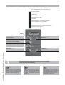
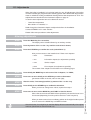
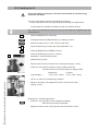
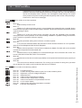
Explanations of symbols and signs on the Control Tower display.
Operation indication
(in the rst display position by technical read out)
0
1
2
3
4
5
6
7
8
9
A
No heat requirement
Ventilation phase
Ignition phase
Burner active on central heating
Burner active on hot water
Fan check
Burner off when room thermostat is demanding
Pump overrun phase for central heating
Pump overrun phase for hot water
Burner off because of to high ow water temperature
Automatic venting programme
display
Central heating
on / off
Domestic hot water (DHW)
on / off
Pump programme
on / off
Installation & Servicing Instructions Strebel Q-boiler range
Mode key
2
Step key
Reset key
Selecting chapters
Selecting chapters
Unlocking the boiler
in case of error
From Good-read out to Technical read out (and vice versa):
- Press 5 sec. on the STEP key.
Water pressure is to low (<0,7 bar), FILL
indication remains continuously visible,
the boiler is taken out of operation. The
installation needs to be topped up.
Water pressure is to low (<1,0 bar), ashing FILL will alternate with indication
of water pressure, boiler power of 50%
is possible. The installation needs to be
topped up.
Water pressure is to high (>2,8 bar), if
HIGH indication remains continuously visible, the boiler is taken out of operation.
The installation pressure needs to be
decreased by draining water.
1
2
3
4
5
6
7
8
9
10
11
12
13
14
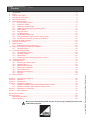
Introduction ....................................................................................................................................4
Rules ............................................................................................................................................4
Scope of the supply........................................................................................................................6
Description of the boiler .................................................................................................................6
Mounting the boiler.........................................................................................................................8
Connecting the boiler .....................................................................................................................9
6.1
Central heating system .......................................................................................................9
6.2
Expansion vessel .............................................................................................................. 11
6.3
Expansion vessel module .................................................................................................12
6.4
Underoor heating system (plastic pipes) .........................................................................13
6.5
Water quality .....................................................................................................................13
6.6
Gas connection .................................................................................................................15
6.7
Hot water supply ...............................................................................................................15
6.8
Condensation drain pipe ...................................................................................................16
6.9
Flue gas exhaust system and air supply system ..............................................................18
6.9.1 Dimensions of the ue gas and air intake duct .................................................................22
External hot water cylinders .........................................................................................................23
Electrical connection ....................................................................................................................24
Boiler controls ..............................................................................................................................26
9.1
Explanation of the function keys .......................................................................................27
Filling and venting the boiler and installation ...............................................................................28
10.1 Hot water supply ...............................................................................................................28
Commissioning the boiler .............................................................................................................29
11.1 Central heating system .....................................................................................................29
11.2 Hot water supply ...............................................................................................................29
11.3 Adjustments ......................................................................................................................30
11.4 Activating factory settings (green key function) ................................................................32
Isolating the boiler .......................................................................................................................33
Commissioning .............................................................................................................................33
13.1 Checking for contamination ..............................................................................................34
13.2 Checking the O2 ...............................................................................................................35
13.3 Maintenance activities.......................................................................................................36
13.4 Draining the installation.....................................................................................................38
13.5 User's instructions .............................................................................................................39
13.6 Maintanance frequency.....................................................................................................39
13.7 Warranty............................................................................................................................39
Error indication .............................................................................................................................40
Annex A
Annex B
Annex C
Annex D
D.1
D.2
Annex E
Annex F
Technical specications ....................................................................................................40
Additives ...........................................................................................................................42
Dimensions .......................................................................................................................43
Installation examples ........................................................................................................45
Radiator installation without thermostatic radiator valves .................................................45
Radiator installation with underoor heating zone ............................................................46
Declaration of Conformity .................................................................................................47
Kiwa certicate ..................................................................................................................48
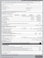
Benchmark Checklist............................................................................................................................49
Service Record .....................................................................................................................................50
Benchmark Checklist ...................................................................................................................45
Service Record.............................................................................................................................46
Work on the installation should only be carried out by qualified personnel with
calibrated equipment.
Installation & Servicing Instructions Strebel Q-boiler range
Content
3
The STREBEL S-HQ is a central heating unit with an optional integrated hot water function.
These units must be connected according to these instructions and all installation norms
in respect of the part of the unit to be connected.
Observe the following rules of safety:
- All work on the unit must take place in a dry environment.
- STREBEL units may never be in operation without their housing, except in connection
with maintenance or adjustments (see Chapter 13 and 14).
- Never allow electrical or electronic components to come into contact with water.
Carry out the following tasks in connection with maintenance, etc. to an already-installed
unit:
- Shut down all programmes
- Close the gas tap
- Remove the plug from the wall socket
- Close the stop cock of the unit’s intake connection
Take note of the following when maintenance or adjustments are needed:
- The unit must be able to function during these activities; for this reason, the unit’s
supply voltage, gas pressure and water pressure must be maintained. Ensure that
these is not a source of potential danger during these activities.
Following maintenance or other activities; always check the installation of all parts
through which gas flows using leak detection fluid (LDF).
Following maintenance or other activities, always replace the housing and secure
it with the screw behind the door at the front of the casing.
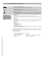
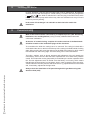
The following (safety) symbols may be encountered in these installation instructions and
on the unit:
This symbol indicates that the unit must be stored away from frost.
This symbol indicates that the packaging and/or contents can be damaged as a
result of insufficient care taken during transport.
KEY-symbol. This symbol indicates that assembly or dismantling, must be
carried out.
ATTENTION symbol. This symbol indicates that extra attention must be paid in
connection with a particular operation.
Useful tip or advice
Installation & Servicing Instructions Strebel Q-boiler range
This symbol indicates that, whilst still in its packaging, the unit must be
protected from weather conditions during transport and storage.
5
3
Scope of the supply
The boiler is supplied ready for use. The supply kit is composed as follows:
•
•
•
•
•
•
4
Condensing
Retrieves heat from
the ue gasses. Water
condensates on the
heat exchanger.
Modulating
Higher or lower burning
according to the heat
demand.
Installation & Servicing Instructions Strebel Q-boiler range
•
•
•
•
Template on the package wrapper;
Installation instructions;
Operating manual;
Warranty card.
Description of the boiler
Room sealed boiler
The boiler retreives its
combustion air to outside then discharges
the ue gasses to the
outside.
6
Boiler with casing;
Automatic vent (inside the boiler);
Safety valve (inside the boiler);
Suspension bracket
Draining valve with T-piece;
Fixing material consisting of plugs and
screws;
Stainless
Super solid kind of
steel which keeps its
quality for life. It will
not rust or erode in
contrast to composition
materials, like aluminium.
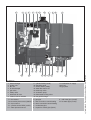
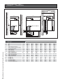
The STREBEL S-HQ boiler is a room sealed, condensing and modulating central heating
boiler, with or without an integrated hot water facility.
The boiler is provided with a compact stainless steel heat exchanger with smooth tubes.
A well thought out principal using durable materials.
The boiler burns gas for supplying warmth. The heat is transferred in the heat exchanger
to the water in the central heating system. By cooling down the ue gasses condensate is
formed. This results in high efciency. The condensate, which has no effect on the heat
exchanger and the function of the boiler, is drained through an internal siphon.
The boiler is provided with an intelligent control system (CMS Control Management
System). The boiler anticipates the heat demand of the central heating system or the
hot water facility.
When an outside sensor is connected to the boiler works weather dependantly. This
means that the boiler control measures the outside temperature and ow temperature.
With this data the boiler calculates the optimal ow temperature for the installation.
Explanation of the type indication:
S-HQ = Type
51 = Nominal load in kW
C = Combi (S = Solo)
STREBEL S-HQ 51C
Statement: No banned materials including asbestos, mercury, CFC's have not or will not
be included in the product.
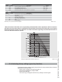
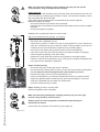
4
2
1
3
5
8 17
16
7
6
18
9
T1 T1a
P1
T2
T3
19
C
R
10
E
K
11 12
13 14
W
15
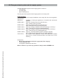
STREBEL Q
1
2
3
4
5
6
7
8
heat exchanger
ignition unit
fan unit
air inlet damper
gas valve
safety valve
automatic air vent
ceramic burner cassette
T1 ow sensor
T1a secondary ow sensor (Q60S)
T2 return sensor
T3 cylinder sensor DHW (combi)
P1 water pressure sensor
gure 4.a
9
10
11
12
13
14
15
16
cylinder DHW (Combi)
operating panel
Control Tower (CMS)
water lter return CH
three-way valve
circulation pump
thermostatic mixing valve
ue gas discharge
17 combustion air supply
18 air box
19 type plate
G
A
R
C
E
gas pipe
ow connection central heating
return connection central heating
condensate pipe
expansion vessel pipe (Q51C)
K cold water pipe (combi)
W hot water pipe (combi)
Installation & Servicing Instructions Strebel Q-boiler range
A
G
7
5
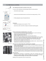
Mounting the boiler
The room where the boiler will be placed must always be frost free.
It is NOT necessary to have a purpose provided air vent in the room or internal space in
which the boiler is installed. Neither is it necessary to ventilate a cupboard or compartment
in which the boiler is installed, due to the extremely low surface temperature of the
boiler casing during operation. Therefore the requirements of BS 6798, Clause 12, and
BS5440:2 may be disregarded.
The boiler can be mounted practically to any wall with the suspension bracket and the
enclosed xing equipment. The wall must be at and of sufcient strength in order to be
able to carry the boiler weight with its water content.
Above the boiler there must be at least 250 mm working space in order to be able to t a
coaxial ue system or a twin supply. On the left side of the boiler at least 50 mm and on
the right side 10 mm must be reserved to allow tting or removing of casing. The location
of the boiler can be determined by using the template located inside the boiler packaging.
Lift the boiler only by the boilers rear wall.
Installation & Servicing Instructions Strebel Q-boiler range
Lifting and carrying precautions:
- Lift only a manageable weight, or ask for help.
- When lifting the boiler, bend the knees, and keep the back straight and feet
apart.
- Do not lift and twist at the same time.
- Lift and carry the boiler close to the body.
- Wear protective clothing and gloves to protect from any sharp edges.
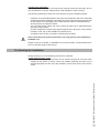
8
Connecting the boiler
The boiler has the following connection pipes;
- The central heating pipes.
These can be connected to the installation by means of compression fittings;
- The gas pipe.
It is provided with a female thread into which the tail piece of the supplied gas isolation
valve can be screwed;
- The condensation drain pipe.
It consists of an oval 24 mm plastic pipe. The drain pipe can be connected to this by
means of an open connection. If the open connection is fitted in a different location,
then the pipe can be lengthened by means of a 32 mm PVC sleeve;
- The ue gas exhaust system and air supply system.
It consists of a concentric connection 80/125 mm.
- Cold and hot water pipes.
Only Combi boilers: These consist of 15 mm copper pipe and can be connected to
the installation by means of compression fittings.
It is recommended that isolation valves are fitted to all heating and hot water
connections to facilitate ease of future maintenance.
It is advisable to spray-clean all of the unit’s connecting pipes and/or to sprayclean/blow-clean the installation before connecting it to the unit.
6.1 Central heating system
Connect the central heating system according to the actual regulations.
The boiler pipes can be connected to the installation by means of compression ttings.
Reducers should be used for connecting to thick-walled pipe (welded or threaded).
When removing the plastic sealing caps from the pipes, contaminated testing
water may be released.
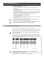
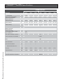
The boiler has a self-adjusting and self-protecting control system for the load and the pump
capacity. This means the temperature difference between the ow and return water is
checked. Table 6.1.a shows the water displacement which supplies the circulation pump
at certain installation resistance.
Boiler type
pump type
water flow rate
permissible installation
resistance
UPER
l/min
l/h
kPa
mbar
Q25C
20-60
16,2
972
29
290
Combi Q38C
20
200
47
470
Solo
20-70
24,6
1478
Q51C
20-70
30,1
1803
Q25S
20-60
9,7
583
Q25S
20-60
16,2
972
32
320
Q38S
20-70
24,6
1478
22
220
Q51S
20-70
30,1
1803
20-70
38,9
2333
Q60S
Installation resistance
table 6.1.a
A low velocity header must be connected to the Q51C, Q51S and Q60S to
prevent flow problems over the boiler.
STREBEL supplies the AA1OV09U Low velocity header for 1 boiler. This can be
connected directly under the boiler on the ow and return pipe.
Installation & Servicing Instructions Strebel Q-boiler range
6
9
external installation pump
with low velocity header
gure 6.1.a
100%
H(m)
UPE
R 20
-70
100
%U
PER
25
%
20-
60
UP
ER
20
Q25
C, Q
38C
Q2
5S,
Q3
8S
If the installation resistance is higher than the stated value the pump will rotate at
maximum pump capacity and the load will be adjusted until an acceptable temperature
difference between ow and return water has been obtained. If, after this, the temperature
difference remains to much then the boiler will switch itself off and wait until an acceptable
temperature has arisen ('T 20°C).
If an unacceptable temperature is detected, then the control will repeatedly try to achieve
water ow, and if this does not work then the boiler will switch off.
If the capacity of the boiler pump is insufcient, an extra external pump can be installed
in combination with a low velocity header in series with the boiler. The electrical side of
this external circulation pump can be connected in the Control Tower, which means this
pump switches at the same times as the boiler pump.
The maximum absorbed current consumption of the external circulation pump may be
230 W (1 Amp). The extra external pump must be selected according the installation
resistance and required ow.
-7
0
25
%
UP
ER
20
-6
0
Q(m³/h)
Installation & Servicing Instructions Strebel Q-boiler range
pump index lines
10
graph 6.1.a
As standard the boiler is provided with a water lter in the return pipe of the boiler. With
this, possible contamination of the central heating water is prevented from ending up in
the boiler. The boiler is also provided with an internal safety valve set at 3 bar. This is
connected to the waste discharge together with the condensation discharge.
If all, or a large part of the radiators are provided with thermostatic radiator valves it is
advisable to use a pressure difference control (bypass) in order to prevent ow problems
in the installation.
The boiler is designed to be used on sealed system only.
Additives in the installation water are only permitted in consultation with the
country distributor. See chapter 6.5.
When using more than one boiler in an installation please refer to the cascade installation
instructions.
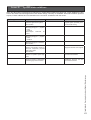
6.2 Expansion vessel
The central heating system must be provided with an expansion vessel. The expansion
vessel which is used should be geared to the water content of the installation. The precharge pressure depends on the installation height above the mounted expansion vessel.
See table 6.2.a.
installation height above
the expansion vessel
pre-charge pressure
of the expansion vessel
5m
0,5 bar
10 m
1,0 bar
15 m
1,5 bar
choice of expansion vessel
table 6.2.a
All Combi boilers are provided with an expansion vessel connection. This pipe is
connected between the three way valve and boiler pump. This prevents the expanding
water, during hot water production, from being closed off from the expansion vessel,
when the thermostatic radiator valves are fully closed. A second expansion vessel in the
installation is not a problem.
In connection with correct functioning of the boiler it is necessary for the
expansion vessel to be connected to the expansion vessel pipe of the boiler.
Installation & Servicing Instructions Strebel Q-boiler range
The Solo boilers are not provided with an expansion vessel connection. When one of
these Solo boilers is combined with a cylinder then one has to take into account that
the expansion vessel should be connected between the three-way valve and the boiler
circulation pump.
11
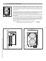
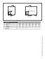
6.3 Expansion vessel module
The STREBEL S-HQ25S and Q38S boilers can be provided with an expansion vessel
module. This means the external expansion vessel is not required. This expansion vessel
module is placed behind the STREBEL S-HQ boiler, which means the expansion vessel
is not noticeable. The content of the two expansion vessels is 20 litres. The pre-charge
pressure is 1 bar.
expansion vessel module
gure 6.3.a
The expansion vessel module can be supplied with the necessary pipes to connect with
the STREBEL S-HQ boiler. The connecting pipes for the installation correspond with
those of the boiler and have the same centre-to-centre distance to the wall.
When checking the expansion vessels these are accessible via the left, right and upper
sides. From these sides the tanks are also removable and the boiler does not have to
be dismantled.
The space which is required for mounting the expansion vessel module corresponds
with the required space for mounting an STREBEL S-HQ boiler. They included template
and mounting strip for the boiler which can be used for the expansion vessel module.
The boiler is tted on to this after the expansion vessel module has been mounted. The
necessary mounting strip for the boiler is present on the module.
Article numbers:
the expansion vessel module without pipe connections AEM0209U
pipe connections for expansion vessel module
ALE0004U
480
155
540
385
12
105
wall
Installation & Servicing Instructions Strebel Q-boiler range
660
270
120
side view of the module with boiler (dimensions in mm)
gure 6.3.b
front view of the module with boiler (dimensions in mm) gure 6.3.c
6.4 Underfloor heating system (plastic pipes)
When connecting or using an underoor heating system, designed with plastic pipes, or
plastic pipes are used elsewhere in the installation,one should ensure that the plastic
pipes used comply with the DIN 4726/4729 standard. It is set out in this standard that the
pipes may not have oxygen permeability higher than 0.1 g/m³.d at 40°C. If the system
does not comply with this DIN standard, the underoor heating component will have to
be separated from the central heating appliance by means of a plate exchanger.
No recourse can be made to the terms of the warranty in the event of failure to
observe the regulations pertaining to plastic underfloor heating pipes.
6.5 Water quality
Fill the installation with drinking water.
In most cases, a heating system can be lled with water according to national standards
for water and treatment of this water is not necessary.
In order to avoid problems with the CH-installations, the quality of the lling water has to
meet the specications mentioned in table 6.5.a:
If the lling water does not meet the required specications, you are advised to treat the
water to such an extent that it does meet the required specications.
Installation:
- The use of groundwater, demi-water and distilled water is prohibited. (on the next
page you will nd an explanation of these denitions)
- If the drinking water quality meets the specications mentioned in table 6.5.a, you
can start ushing the installation before installing the device.
- Whilst ushing, corrosion products (magnetite), tting products, cutting oil and other
undesirable products have to be removed.
- Another possibility is to remove the pollution by installing a lter. The lter type has
to t the type and grain size of the pollution. STREBEL recommends lter usage.
- In this case, the whole piping system should be taken into consideration.
- The CH-installation has to be properly vented before using the system. For that
purpose, we refer to the commissioning chapter.
- If a regularly water top up is required (>5% on an annual basis), then there is a
structural problem and an installer has to solve the problem. Adding regularly fresh
water to the system also adds additional calcium and oxygen implying that magnetite
and calcium residues can continue. The result may be blockages and/or leakages.
- The use of anti-freeze and other additives requires periodical quality checks of the
lling water in accordance with the period laid down by the additives supplier.
- Chemical additions are to be avoided and should only be used after STREBEL has
approved their corresponding use.
- Should you wish to achieve the required water quality by using chemical additives,
then this is your own responsibility. The warranty on the product delivered by
STREBEL expires, if the water quality does not meet STREBEL's specications or
the chemical additives have not been approved by STREBEL.
- On installation and during additions or changes at a later stage, STREBEL recommends
to keep a record of the type of water used, its quality at the time, and if applicable,
which additives and quantities were added.
Installation & Servicing Instructions Strebel Q-boiler range
The warranty becomes invalid, if the installation is not being flushed and/or the
quality of the filling water does not meet the specifications recommended by
STREBEL. Always contact STREBEL in advance, if things are not clear or you
wish to discuss any deviations. Without approval, the warranty becomes invalid.
13
Parameter
Value
Water type
Potable water
Softened water
6.0-8.5
pH
6.0-8.5
Conductivity (at 20°C in S/cm)
Max. 2500
Iron (ppm)
Max. 0.2
Hardness (°dH)
Installation volume/capacity 1-7
<20 l/kW
1-12
Installation volume/capacity
Refer to Additives Attachment
>=20 l/kW
1-7
Oxygen
No oxygen diffusion allowed during operation.
Max. 5% lling water addition annually
Refer to Additives Attachment
Corrosion inhibitors
Refer to Additives Attachment
pH increasing or lowering agents
Refer to Additives Attachment
Anti-freeze additives
Refer to Additives Attachment
Other chemical additives
Refer to Additives Attachment
Solid substances
Not allowed
Residues of processing water not forming Not allowed
part of the drinking water
table 6.5.a
Water quality in DHW facility
Parameter
Value
Water type
Potable water
pH
7.0-9.5
Conductivity (at 20°C in S/cm)
Max. 2500
Chloride (ppm)
Max. 150
Iron (ppm)
Max. 0.2
Hardness (°dH)
1-12
Installation & Servicing Instructions Strebel Q-boiler range
Number of bacterial colonies at 22°C (num- Max. 100
ber/ml). pr EN ISO 6222
14
table 6.5.b
-
-
When the amount of chloride is above the required specications mentioned above
in table 6.5.b, it is necessary to apply an active anode in case of the use of a DHW
cylinder.If this is not met it will void the warranty for DHW parts of the installation.
When the amount of chloride is above the required specications mentioned above in
table 6.5.b, in case of the use of a combi boiler will void the warranty for DHW parts
of the boiler.
Water type denition:
Potable water:
Tap water compliant with the European drinking water guideline:
98/83/EG dated 3 November 1998.
Softened water:
Water with partly de-ionised calcium and magnesium.
Demi-water:
Virtually completely demineralised water (very low conductivity)
Distilled water:
Water no longer containing minerals.
6.6 Gas connection
The appliance pipe is tted with an internal thread, into which the tail piece of the gas
isolation valve can be screwed.
United Kingdom:
The gas supply must comply to the current Gas Safety Regulations.
The connection to the appliance must include a suitable method of disconnection and a
gas control cock must be installed adjacent to the appliance for isolation purposes. The
nominal inlet working gas pressure measured at the appliance should be 20 mbar for Nat
gas (G20).
Make sure that the gas pipe work does not contain dirt, particularly with new
pipes.
When the boiler has to be converted from natural gas to LPG, STREBEL provides special
kits for this purpose. Special instructions are supplied with the kit.
Always check the installation of all of the parts through which gas flows using
leak detection fluid (LDF).
6.7 Hot water supply
Connection of the drinking water installation should be done according to the national
water laws.
The sanitary water pipes can be connected to the installation by means of compression
ttings. The cold water inlet on the Combi boilers must be provided with the following
(counted in the water ow direction):
Dosing valve (supplied), Safety group, Expansion vessel 6bar (potable water, blue).
With a water pressure lower than 1.5 bar it is advisable to remove the inside mechanism
of the dosing valve.
Installation & Servicing Instructions Strebel Q-boiler range
A dosing valve must be tted in the cold water pipe. The dosing valve ensures that
a quantity of water is supplied which has a guaranteed outlet temperature of 60°C
(assuming a cold water temperature of 10°C). The quantity of water is virtually unaffected
by the water pressure.
15
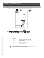
6.8 Condensation drain pipe
All STREBEL wall hung gas red condensing boilers contain a syphonic condensate trap
to collect and realease condensate.
The amount of condensate formed is determind by the type of boilers and the water
temperature produced by the boiler.
Condensate pipework.
Use plastic pipework of a diameter no less than 25mm.
Routing of the pipework,
Wherever possible, the condensate pipework should be routed internally to prevent
freezing.
The condensate pipework must fall at least 50mm per metre towards the outlet and take
the shortest possible route
Support the pipe at least every 50 cm for near horizontal sections and 1 metre for vertical
sections
External pipework
The pipework should be kept to a minimum and the route as vertical as possible.
Do not exceed 3 metres outside the dwelling.
The condensate pipe must be run using suitable corrosion resistant materials (eg. plastic).
Terminate as close to the ground or drain as possible (below the grating and above the
water level) while still allowing for safe dispersal of the condensate.
Connection of a condensate drainage pipe to a drain may be subject to local building
controls.
Pipework subjected to extreme cold or wind chill conditions should be in a 40mm diameter
pipe.
Installation & Servicing Instructions Strebel Q-boiler range
Protect all external pipework with weather resistant insulation and, if necessary, box in,
to reduce the risk of freezing.
16
Making it safe.
Condensate pipework must not leak, freeze or block up.
Condensate traps must be lled before ring the boiler to prevent the possibility of potential
harmfull ue products evacuating via the condensate route.
Do not dispose condensate into a water recovery system where it is recaimed for reuse.
Condensate can be discharged into a rainwater hopper which is part of a sewer carrying
both rain water and foul water.
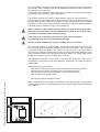
Final discharge options.
The condensate pipe can only terminate into any one of the ve areas as shown in the
diagrams on this page.
Draining of the condensation water to the external rain guttering is not
permitted in view of the danger of freezing.
A
B
C
D
E
F
G
H
J
K
L
Drain requirements
-Condensate from boiler syphon/trap
-Sink with internal overow
-25mm dia. Plastic condensate pipe
-External drain or gully
-Internal soil and vent stack.
-Servicable condensate trap (75mm min.)
-300mm x 100mm dia. sealed plastic tube.
-Ground level
-Drainage holes facing away from the building
-Lime stone chippings
-Weather resistant insulation
figure 6.8.a
Installation & Servicing Instructions Strebel Q-boiler range
Before putting the boiler into operation fill the syphon with 300 ml of
water.
17
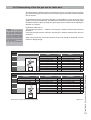
6.9 Flue gas exhaust system and air supply system
The ue gas exhaust system and air supply system consists of:
- Flue gas pipe;
- Air supply pipe;
- Roof or wall terminal.
The ue gas exhaust system and air supply system must comply with:
United Kingdom:
The ue gas outlet and air supply installation must comply with the current regulation
requirements:
IGE/UP/10;
Installation of ued gas appliances in industrial and commercial
premises
BS EN 1856-1;
Chimneys - Requirements for metal chimneys Part 1: System chimney products
BS EN 1856-2;
Chimneys - Requirements for metal chimneys Part 2: Metal liners and connecting ue pipes
BS EN 15287-1; Chimneys - Design, installation and commissioning of chimneys Part 1: Chimneys for non-room sealed appliances
BS EN 15287-2; Chimneys - Design, installation and commissioning of chimneys Part 1: Chimneys for room sealed appliances
BS EN 13384-2; Chimney - Thermal and uid dynamic calculation methods Part 2: Chimneys serving more than one heating appliance
Clean Air Act;
For multiple boiler application where total heat input exceeds
366.4 kW [ or 150 kW as advised within the CAAM, refer to local
authority ]
Furthermore:
- Boiler Class indicated on the boiler’s type plate (Flue category)
- Locally applicable rules.
- The supplier’s installation instructions
Installation & Servicing Instructions Strebel Q-boiler range
When in doubt or if you have any questions, always contact STREBEL Ltd..
18
The boiler can be tted with a parallel connected ue gas outlet and air supply system
(the connection diameter for both channels is ø100mm) or a concentric ue gas outlet
and air supply system. In that case, the connection diameter is ø100/150mm. Refer to
chapter 7.1 or 7.2.
The appliance connection diameter is 80/125 mm, to which the ue gas outlet and air
supply system can be tted, with or without elbow pieces. The maximum permissible
pipe length is set out in Table 6.9.1.a.
All ue gas parts, which are outside the re
resistant cover, need to be in stainless steel.
PP
SS
Air filter
BoilerClass B
Free exhaust area
SS
PP
PP
PP
SS
PP
PP/MW
PP/MW
PP/MW
Boiler Class C
Permitted only
when the air
intake and the flue gas
outlet are in the same
pressure area.
Room sealed system
Open boiler en roomsealed system
gure 6.9.a
Installation & Servicing Instructions Strebel Q-boiler range
Open boiler
19
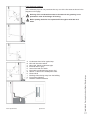
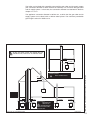
Boiler conversion from concentric to parallel
It is also possible to use a parallel pipe connection of 2x 80mm. In this case a conversion
kit 'concentric to parallel' should be ordered. Art.nr. S4440520.
A
A.
1. Push the 2 clips slightly outwards.
B.
2. Pull the concentric adaptor out of the boiler.
3. Press the cover in the connection at the back from inside out.
C.
4. Pull the rubber seal around the bottom of the ue connector.
5. Push the ue connector in the boiler, in the boiler ue pipe until
‘CLICK’.
6. Push the ø125mm cover over the ue connector in the ø125mm
opening until ‘CLICK’.
7. Push the rubber plug in open position in the O2 measuring opening and
close the stop.
8. Push the gasket around the top of the ue connector.
D.
Connect the parallel ue gas and air intake system (2x ø80mm).
1
B
2
3
C
8
6
5
7
4
Installation & Servicing Instructions Strebel Q-boiler range
D
20
boiler conversion from
concentric to parallel
figure 6.9.a
We advise to build a simple ue gas system and air supply system out of table 6. For
further information about the available components of the ue gas and air supply system
we recommend you consult STREBEL Ltd..
The STREBEL ue gas system is meant and designed solely the use on STREBEL central
heating boilers adjusted for Nat gas or LPG. The maximum ue gas temperatures are
below 70°C (full load 80/60°C)
The proper operation can be inuenced harmfully by changes of or adjustments to the
correct set up.
Possible warranty claims will not be honoured if incorrect changes result in non compliance
with the installation manual or local rules and regulations.
The ue gas systems described in this document are solely suited for STREBEL central
heating boilers of the STREBEL boiler range. For this purpose the CE Certicate has
been supplemented under the Gastec nr: 0063BQ3021, 0063AS3538 and 0063AU3110.
The ue gas system should be built up using only STREBEL program products.
Horizontal ue system should always be installed sloping towards the boiler, in order to
avoid condensate lying in the ue system.
The minimum gradient is 50mm/Mtr. With the condensate running back to the boiler the
risk of ice forming at the terminal is reduced.
minimum
distance
terminal position for fan assisted boiler
A
gure 6.9.b
directly below an open window or other opening
mm
(e.g. air brick)
300
B below gutters, soil pipes or drain pipes
mm
75
C below eaves
mm
200
D below balconies or car port roof
mm
200
E from vertical drain pipes and soil pipes
mm
75
F from internal or external corners
mm
300
G above ground or below balcony level
mm
300
H from a surface facing a terminal
mm
600
I
from a terminal facing a terminal
mm
1200
J
from an opening in the car port (e.g. door
window) into dwelling
mm
1200
K vertically from a terminal on the same wall
mm
1500
L horizontally from a terminal on the same wall
mm
300
M horizontally from a vertical terminal to a wall
mm
300
Dimensions
table 6.9.a
Installation & Servicing Instructions Strebel Q-boiler range
The terminal should be located where dispersal of combustion products is not impeded
and with due regard for the damage or discolouration that might occur to building products
in the vicinity (see g 6.9.b).
21
In certain weather conditions condensation may also accumulate on the outside of the
air inlet pipe. Such conditions must be considered and where necessary insulation of
the inlet pipe may be required.
In cold and/or humid weather water vapour may condense on leaving the ue terminal.
The effect of such ‘plumeing’ must be considered.
The terminal must not be located in a place where it is likely to cause a nuisance.
For protection of combustibles, refer to IS 813 section 9.10.1. where the terminal is less
than 2m (6.6ft) above a pavement or platform to which people have access (including)
any balcony or at roof the terminal must be protected by a guard of durable material.
A suitable guard is available from the country distributor.
Where a terminal is fitted below a window which is hinged at the top, and where
the hinge axis is horizontal, and the window opens outwards, the terminal shall
be 1m below the bottom of the window opening.
If the boiler is to be located under stairs, a smoke alarm meeting the
requirements of I.S. 409 or equivalent must be fitted.
The flue must be terminated in a place not likely to cause a nuisance.
For horizontal sections, the outlet system should always be tted on an incline (50
mm/m) sloping down towards the appliance so that no condensation water is able to
accumulate in the outlet system. The chances of icicles forming on the roof outlet is
minimised by causing the condensation water to run back towards the appliance. In the
case of horizontal outlets the inlet system should be tted on an incline sloping down
towards the outside to prevent rainwater from coming in.
The appliance produces a white wisp of condensation (plumeing). This wisp of
condensation is harmless, but can be unattractive, particularly in the case of outlets in
outside walls.
Cutting the pipe goes as follows:
- Take out the inner tube by turning it until it releases from its security position;
- Cut just as much from the air intake part as from the ue gas part;
- Take off the burrs from the cutting edge to prevent cutting the seals;
- Click the pipes back together again.
Installation & Servicing Instructions Strebel Q-boiler range
Use special grease to simplify the tting
22
When mounting the ue gas system, pay attention to the ow direction. An arrow on the
product points this out. It is not permitted to mount a system upside down and will lead
to complaints.
Dismantlement and shorten pipes
figure 6.9.c
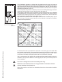
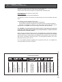
6.9.1 Dimensioning of the flue gas and air intake duct
The ue diameter is determined by the total length of the run, including for the connection
pipe, elbows ttings and terminal covers etc and the type and number of boilers installed
into the system.
An undersized ue pipe can lead to disorders. Look at table 6.9.1.a for the choice of the
system and the correct diameter. The table below shows the maximum ue lengths with
the different boiler outputs. A longer ue gas length can be achieved by increasing the
diameter to ø 100mm.
Example:
A 25kW with a concentric
ue gas system ø80/125mm
has according to the table a
maximum ue straight length
of 31m In the system that is
going to be put in there are 2
x 45° bends, so the maximum
ue gas length is
31 – ( 2 x 1.1 ) = 28.8 meters.
Explanation table 6.9.1.a:
Two pipe ue gas system: maximum noted length = distance between boiler and roof
terminal A
Concentric ue gas system: maximum noted length = distance between boiler and roof
terminal B
When using bends the noted value behind every bend should be deducted from the
maximum straight length.
Two pipe flue system + chimney lining
ø80mm
Maximum straight lenth 80
87° bend resistance length
45° bend resistance length
Maximum straight lenth 80
87° bend resistance length
45° bend resistance length
Maximum straight lenth 80
87° bend resistance length
45° bend resistance length
16-25 kW
26-38 kW
39-60 kW
A
in m
31
-1,5
-0,8
18
-1,5
-0,8
6
-1,5
-0,8
ø100mm
Maximum straight lenth 100
87° bend resistance length
45° bend resistance length
Maximum straight lenth 100
87° bend resistance length
45° bend resistance length
Maximum straight lenth 100
87° bend resistance length
45° bend resistance length
A
in m
40
-1,8
-0,9
39
-1,8
-0,9
18
-1,8
-0,9
B
in m
31
-2,8
-1,1
13
-2,8
-1,1
6
-2,8
-1,1
ø100/150mm
Maximum straight lenth 100/150
87° bend resistance length
45° bend resistance length
Maximum straight lenth 100/150
87° bend resistance length
45° bend resistance length
Maximum straight lenth 100/150
87° bend resistance length
45° bend resistance length
B
in m
40
-2,6
-1,1
34
-2,6
-1,1
10
-2,6
-1,1
ø60/100mm
16-25 kW Maximum straight lenth 60/100
87° bend resistance length
45° bend resistance length
26-38 kW
39-60 kW
Dimensions ue gas system and air supply system
Table 6.9.1.a
Installation & Servicing Instructions Strebel Q-boiler range
Concentric flue system
B
in m
ø80/125mm
12 Maximum straight lenth 80/125
-1 87° bend resistance length
-1 45° bend resistance length
Maximum straight lenth 80/125
87° bend resistance length
45° bend resistance length
Maximum straight lenth 80/125
87° bend resistance length
45° bend resistance length
23
7
External hot water cylinders
Depending of the comfort preferences different external hot water cylinders can be
connected to the boiler. The choice of the cylinder depends on the coil output. The coil
output must comply with the boiler output.
Installation & Servicing Instructions Strebel Q-boiler range
A cylinder which is used in combination with a Q 51S or Q 60S, should have a minimal
capacity of 40 kW resp. 45kW (minimal ø28mm coil). The maximum permitted pressure
drop is respectively 20 and 10 kPa at a ow of respectively 1417 and 1587 l/h.
See installation example 17.2 on page 40 for the hydraulic connection.
24
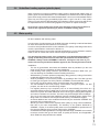
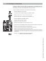
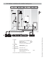
8
Electrical connection
The appliance complies with the CE Machinery Directive 89/392/EEC. The EC Low Voltage
Directive 72/23/EEC and the EC EMC Directive 89/336/EEC.
A 230V -50Hz mains electrical supply is required fused externally at 5A.
The installation must continue to comply with:
United Kingdom:
- the national rules for electrical installations.
The appliance must be connected to an earthed socket. this must be visible and within
reach.
The following general stipulations also apply:
- No changes may be made to the wiring of the appliance;
- All connections should be designed in accordance with the enclosed regulations.;
- Should it be necessary to change it, the mains power supply cable may only be
replaced with an STREBEL mains power supply cable (item No. S4407300).
The STREBEL room thermostat and controls must be connected to their allocated
connections. All other types or makes of room thermostats or controls which are
used must have a Volt free contact.
When using an on/off thermostat or control, it is possible that an anticipating resistance
must be installed in order to prevent too high temperature uctuations. As a standard
rule this means mercury thermostats. This resistance wire is present in the Control Tower
and must be connected to clamps 23 and 27. The anticipating resistance in the room
thermostat has to be set at 0.11 A.
Connection terminal
24 Volts
maximum 100 mA
External safety contact
On/off thermostat or
control (Volt free)
room thermostat
outside sensor
internal or external
three-way valve motor
and cylinder sensor
230 Volts
230 Volts for external control
230 Volts for external pump
mains power
supply
Connection terminalQ
figure 8.a
Installation & Servicing Instructions Strebel Q-boiler range
For more detailed questions regarding the components which are not supplied, the
country distributor should be contacted.
25
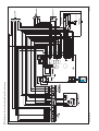
26
electrical diagram
Installation & Servicing Instructions Strebel Q-boiler range
flow sensor (T1a). Only Q60S
gure 8.b
9
Boiler controls
The boiler is provided with a fully automatic microprocessor control, called CMS Control
Management System. This control simplies operation by undertaking all major control
functions. Initially when power to the unit is switched on it will remain on standby. There
is no indication Led on, untill one of the programme keys is pressed. The control panel
display will show the relevant state. When the installation is empty the display will show
FILL.
The various parameters can be called up in two ways:
The Good-state or standard read out
The rst way shows a simple display read out.
The boiler in operation will always show 'Good'. When a message is necessary this will
be shown instead of Good.
Technical read out
The second way is a technical read out. In normal situations the following will be shown:
• on the left the status in which the boiler is active;
• on the right the ow temperature;
• the water pressure in the installation.
When a message (error or blocking code) is necessary this will be shown instead of the
technical read out..
To switch over from the Good-state to the Technical read out (and vice versa):
- Press 5 sec. on the STEP-key.
When the system has been lled the automatic venting program starts, when a programme
has been selected, by pressing the key for Central Heating, DHW or pump programme
(
,
or
). The programme takes 17 minutes and stops automatically. After this
the unit will function normally. (See also 'Filling and venting the boiler and installation).
Installation & Servicing Instructions Strebel Q-boiler range
On a call for heating or hot water the control system will select the required water control
temperature. This water temperature is called the T-set value. On a call for central heating
the boiler ignites rst at low input. The input is then changed slowly to match the load
required. The boiler operates in this way to avoid excessive water noises and temperature
overshoot. On a call for hot water supply the T-set value of central heating return water
temperature is monitored. Depending on the amount of sanitary water which is withdrawn
from the DHW cylinder, the central heating return water temperature, from which the
input is adjusted, will vary.
27
9.1 Explanation of the function keys
When the pump is
switched on continuously
it can lead to undesired
heating up of the central
heating system during the
summer.
-
Central Heating programme key.
Switching the Central Heating on or off (Led on/off);
-
Hot Water programme key.
Switching the Domestig Hot Water (DHW) facility on or off (Led on/off);
-
Pump programme key.
adjusts the pump to continuous water circulation in the central heating system (Led
on), or according to the pump overrun times on the relevant programs (Led off);
•
Mode-key.
After briefly pressing, a selection of the data chapters can be retrieved.
After pressing for 5 seconds it is possible to enter the code as described in chapter
11.3;
Step-key.
After briefly pressing, the water pressure can be retrieved and pages per chapter can
be retrieved.
After pressing for 5 seconds it switches from the Good-state to technical read out and
vice versa;
Reset-key.
After briefly pressing, for:
- unlocking errors;
- ending the access code;
After pressing for 5 seconds an operating stop is made, for example, for activating
the automatic venting programme.
•
•
Installation & Servicing Instructions Strebel Q-boiler range
Some keys have other functions.These functions are only active when according to the
procedure described in chapter 11.3, adjustment has to be changed or data must be
retreived from the CMS.
The other functions are:
28
-
Central Heating programme key :
-
Hot Water programme key:
Pump programme key :
Step-key:
+ function;
- function;
store-function; a modied setting is conrmed;
scrolling in a data chapter.
10
Filling and venting the boiler and installation
The central heating installation needs to be lled with potable water. For lling or topping
up the installation you use the lling loop according to the following procedure:
1
Switch on the power supply;
2 The diplay will show FILL;
3
All functions off (heating, DHW and pump);
4 Push briey the 'STEP'-button: P x.x = water pressure in bar;
5
Open the lling loop (Indication on display increases);
6 Fill up slowly to 1.5 to 1.7 bar;
7
STOP appears on the display;
8 Close the lling loop;
9
De-aerate the complete installation, start at the lowest point;
10 Check the water pressure and if necessary top it up;
11 Close the lling loop;
12 Activate the functions in use (heating
, DHW
and/or pump
);
13 If A xx appears on the display, wait for 17 minutes;
14 Check the water pressure and if necessary top it up to 1,5 to 1,7 bar
15 Close the lling loop;
16 Press the ‘STEP’-button;
17 Be sure that the lling loop is closed.
18 After the automatic de-aeration programm (A xx) is nished the boiler will return to
Check the water pressure regularly and top up the installation when necessary.
The working pressure of the installation should be between 1.5 and 1.7 bar when the
installation is cold.
It can take a while before all air has disappeared from a filled installation.
Especially in the first week noises may be heard which indicate the presence
of air. The automatic air vent in the boiler will make this air disappear, which
means the water pressure can reduce during this period and therefore topping
up with water will have to be done.
10.1 Hot water supply
Apply the water pipe pressure to the cylinder (open main valve and/or stop valve of the
safety group).
Vent the cylinder and the hot water installation by opening a hot water tap. Leave the
tap open for as long as required until all air has disappeared from the cylinder and the
pipes and only water is owing from the tap.
Installation & Servicing Instructions Strebel Q-boiler range
the Good state or Technical read out.
29
11
Commissioning the boiler
Before the boiler is red, ensure that the boiler and the system are well vented and
free of air. Purge the gas line between the gas meter and the boiler and carry out a gas
soundness test as specied in the current Gas Safety Regulations.
The boiler does not require adjustment of the burner pressure and air quantity because
it is self adjusting and is factory set at the correct value.
11.1 Central Heating system
Provided there is a heat requirement from the thermostat or control, the central heating
key (central heating
programme will be put into operation by means of the
programme). The circulation pump will start circulating and the boiler will start the burner.
11.2 Hot water supply
Provided there is a heat requirement from the cylinder the hot water programme will be
put into operation by means of the
key (hot water programme).
Installation & Servicing Instructions Strebel Q-boiler range
Depending on pipework and wiring configurations the boiler will operate with a
priority to hot water.
30
11.3 Adjustments
When the boiler is installed it is in principal ready for use. All adjustments of the boiler
control are already pre-programmed for a heating system with radiators with large surface
areas or underoor heating as additional heatings with a ow temperature of 70°C. The
adjustments are described in the Parameter chapter on page 31.
In certain cases adjustment have to be altered in case of :
-
Lower ow temperature
More boilers in Cascade, i.e..
Read through the Parameter chapter to adjust the boiler to its installation.
Contact STREBEL Ltd. in case of doubt.
Please follow next procudere to alter adjustments:
Altering adjustments
STEP 1
Press the Mode-key for 5 secondss.
The display shows COdE followed by an arbitrary number;
STEP 2
Press by means of the + or the - key until the code C123 is shown;
STEP 3
Press the STORE-key to confirm the code (code blinks1 x).
Now you have acces to the installer level. There are 4 chapters:
• PARA
Parameters
• INFO
Information chapter (no adjustments possible)
• SERV
Service chapter
• ERRO
Error-chapter (no adjustments possible)
STEP 4
Press briefly the MODE-key to select one of the 4 chapters, i.e. PARA;
STEP 5
Press once or more briefly on the STEP-key to select a Parameter
(parameter visible on the left, value on the right) ;
STEP 6
Alter the value, if necessary/possible, by means of the + or the - key
STEP 7
Press briefly on the STORE-key to confirm the alteration.
When you have to change more values, repeat from step 5.
STEP 8
Press once or more on the MODE-key until StBY or Good is shown:
After a few seconds the text StBY will be replaced by the technical read-out or
Good-state (Depending from the position the acces code is keyed in)
When you want to return from an arbitrary position to the original read out press
once or more on the MODE-key until StBY is shown.
After 20 minutes, if no single key is used the display will return automatically to its original
read-out (Good state or technical read out)
Installation & Servicing Instructions Strebel Q-boiler range
The content of the chapters is described on the following pages.
31
Parameter-Mode
PARA
Factory
1
70°C
2*
02
3
4*
5*
6*
7*
10*
11*
14
15*
23
27
31
36
43
45
48
49
60
Installation & Servicing Instructions Strebel Q-boiler range
89
32
.
max.
00
2.3
1.4
-10
0°C
0°C
5
0
-3°C
0°C
63°C
0
max.
0
25% (50%)
100%
03
00
.
Description
Range
maximum flow temperature CH
20 - 85°C
type of CH installation:
radiators; air heating; convectors:
01
T max. flow 85°C; K factor heating line 2.3; gradient 5°C/min; gear
differential 6°C
radiators with large surface areas or underfloor heating as additional heating: 02
T max. flow 70°C; K factor heating line 1.8; gradient 5°C/min; gear
differential 5°C
under floor heating with radiators as additional heating:
T max. flow 60°C; K factor heating line 1.5; gradient 4°C/min; gear
differential 4°C
full under floor heating:
T max. flow 50°C; K factor heating line 1.0; gradient 3°C/min; gear
differential 3°C
maximum power CH in kW
control principal with on / off thermostat:
100 % on / off thermostat
100 % on / off weather dependant
heating line K-factor (see also heating line graph)
heating line exponent (see also heating line graph)
heating line climate zone (see also heating line graph)
fine adjustment heating line day temperature
fine adjustment heating line night temperature
gradient speed
booster after night reduction:
no
yes
Frost Temperature
Min. flow temperature
Cylinder temperature with external cylinder sensor
Type of three way valve cylinder
VC 2010 / VC 8010
VC 6940
Maximum power DHW in kW
No function
Minimum pump capacity (Q60S)
Maximum pump capacity Heating
Type of communication bus:
Automatic recognition of ATAG Bus or ATAG Z-Bus
(30 Seconds waiting time after connecting BrainQ RSC thermostat)
ATAG Z-Bus
ATAG Bus (BrainQ and MadQ)
Address of boiler in cascade
No function
ATAG Bus thermostat (BrainQ, MadQ)
Cascade boiler 1 to 8 (Always set Par. 60 to 03)
.
03
04
min-max
00
01
0.2 - 3.5
1.1 - 1.4
-20 - 0
-5 to 5°C
-5 to 5°C
0 - 15
00
01
-20 to 10°C
0 to 70°C
40 - 80°C
00
01
min-max
00 - 01
25-100 %
40-100 %
01
02
03
-01
00
00 - 07
.
Info-Mode
INFO
.
Factory
.
1
4
5
7
8
16
17
18
20
21
22
23
24
25
26
32
37
46
48
°C
°C
°C
°C
°C
%
kW
kW
.
.
GJ
GJ
GJ
Std
Std
Std
Std
Std
Std
0,1A
Description
.
.
flow water temperature T1
return water temperature T2
DHW temperature T3
outside temperature T4
flow water temperature T1a
actual power in %
actual power in kW
actual load in kW
indication bus communication
consumption total in GJ (.. x 33 = .. m3)
consumption CH in GJ (.. x 33 = .. m3)
3
consumption DHW in GJ (.. x 33 = .. m )
total number of burner run hours
number of burner run hours CH
number of burner run hours DHW
total number of hours counter
total number of run hours pump CH and DHW
within how many hours is service required
Ionisation current
.
Service-Mode
1
2
3
4
SERV
Value
OFF
OFF
OFF
OFF
Description
boiler in operation with burner function on
fan adjustable and burner off
pump adjustable with burner on
showroom position ON = active and OFF = non active
Range
OFF - max.
OFF - max.
OFF - max.
ON - OFF
.
.
.
.
Error-Mode
ERRO
Value
Err.L - Err.5
1
2
3
°C
4
°C
5
kW
6
%
Description
Last saved error until 5 last predecessing errors
error code
operation status boiler
flow water temperature T1
return water temperature T2
load
pump capacity
Parameter-, Info-, Service- and Error-chapters
Table 11.3.a
outside temperature in °C
heating line adjustments Parameter Step 6 and 7
graph 11.3.a
11.4 Activating factory settings (green key function)
To activate the factory settings again please follow the next procedure (Note: all altered
adjustments will be set back):
- Select, when necessary, the technical read out;
- Select with the MODE-key chapter PARA;
- Press the STORE-key.
The word "Copy" will appear and the facory settings are active again.
Installation & Servicing Instructions Strebel Q-boiler range
ow water temperature in °C
* Most of the data in this table can be requested by the BrainQ. Most of the adjustments which are stated in
this table are unnecessary when in combination with the BrainQ thermostat and will be taken care of by the
BrainQ itself and do not have to be adjusted. For further information regarding to the BrainQ thermostat we
refer to the BrainQ installation manual.
33
12
Isolating the boiler
In some situations it may be that the entire boiler must be switched off. By switching
off the three keys with the lamps for central heating, hot water and pump programme
,
or
), the boiler is switched off. Leave the plug in the wall socket, which
(
means the circulation pump and the three-way valve are activated once every 24 hours
in order to prevent jamming.
In the event of frost danger it is advisable to drain the boiler and/or the
installation.
13
Commissioning
Work on the boiler must be carried out by a competent person, (Ref: Gas Safety
Installation, Use and Regulations ) using correctly calibrated instruments with
current test certication.
At the time of commissioning, complete all revelant sections of the Benchmark
Checklist located on the inside back pages of the document.
To commission the boiler the casing has to be removed. The casing is locked with a
screw behind the door on the front and the top of the casing is hooked behind a locking
edge. After removing this screw the casing must be lifted at the bottom by which means
it is released from the locking edge. Then the casing can be removed forward.
The boiler settings, such as burner pressure and adjustment of the air quantity are
unnecessary, due to the fact that the boiler operates with a so-called zero pressure
control. This means the correct gas quantity is controlled by the suction operation of the
fan. The ne adjustment which is carried out at the factory is once-only, which means
that adjusting of these values is unnecessary. Only in case of replacing of the gas valve,
venturi and/or fan the zero pressure and the incorrect O2 adjustment has to be checked
and, if necessary, adjusted at the right value.
Installation & Servicing Instructions Strebel Q-boiler range
Always check the installation of all parts through which gas flows using leak
detection fluid (LDF)
34
13.1 Checking for contamination
In order to be able to check the boiler for contamination in the following years it is
advisable to measure the maximum air displacement in the boiler when putting the boiler
into operation. This value can be different with each type of boiler.
Test nipple
-
Press the MODE-key for 5 seconds.
-
The diplay will show COdE followed by an arbitrary number;
-
Select by means of the + or the - key the code C123;
-
Press the Store-key to conrm the code (code blinks 1 x);
-
Press the MODE-key until SERV is shown;
-
Press the STEP-key until 2 is shown;
alternately 2 and OFF will be shown.
-
Undo the top test nipple on the gas valve (g. 13.1.a);
-
Connect the hose of the digital pressure gauge to the top test nipple of the gas valve
-
Press the + key until the maximum value is achieved;
The fan will function to its maximum revolutions (burner stays off)
-
Measure the under pressure and write down this value.
At the next service visit this value may drop by 20% of its original value recorded on
commissioning. If this value has dropped by more than 20% the boiler requires full
maintanance.
-
Press the - key until OFF is shown (keep key pressed)
With this the procedure is nished.
gure 13.1.a
Installation & Servicing Instructions Strebel Q-boiler range
In order to be able to measure this value follow the next procedure:
35
13.2 Checking the O2
The O2 percentage is factory-set. This has to be checked at commissioning,
maintance and faults.
This can be checked by means of the following procedure:
- Remove the black cover of the gas valve by unscrewing the sealed screw.
-
Put the boiler into operation and take care that it can deliver its heat;
Tip: If there is no demand for heat on CH, turn the hot water tap completely open and
measure the O2.
-
Press the MODE-key for 5 seconds.
-
The diplay will show COdE followed by an arbitrary number;
-
Select by means of the + or the - key the code C123;
-
Press the Store-key to conrm the code (code blinks 1 x);
-
Press the MODE-key until SERV is shown;
-
Press the STEP-key once until 1 is shown;
alternately 1 and OFF will be shown.
-
Calibrate the O2 meter ;
-
Place the lance of the O2 meter into the check point (see g. 13.2.a);
-
Press the + key until the maximum value (in kW) is achieved;
The boiler will burn on full load (value on display in kW)
-
O2 percentage =
-
Let the O2 meter do its measuring procedure.
-
Adjust, if necessary, the adjustment screw to correct the O2 value
(see g. 13.2.b).
checkpoint O2
Installation & Servicing Instructions Strebel Q-boiler range
gure 13.2.a
36
Natural gas
4,7% (-1,2%, +0,8%)
Propane
5,1% (-1,2%, +0,7%)
adjustment screw O2
gure 13.2.b
Ending the O2 measuring procedure:
- Press the - key until OFF is shown (keep key pressed).
With this the procedure has ended..
-
Replace the black cover on the gas valve and x it with the screw.
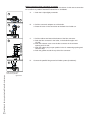
Make sure that during refitting of the clamping rods, they are put into the
correct position. They should be turned vertically.
figure 13.3.e
Ignition electrode
The replacement of the electrode is only necessary when the electrode is worn off. This
can be checked by measuring the ionisation current. The minimum ionisation current
has to be higher the 4A on full load.
If the viewing glass is damaged the complete electrode must be replaced.
Replacement goes as follows:
- remove the electrical connections of the electrode;
- press the clips on both sides of the electrode to both sides and remove the complete
electrode;
- remove and replace the gasket;
Retting of the components is done in reverse order.
9
10
8
Siphon and condensate tray (see g. 13.3.f and g)
Step 1: Siphon
- rst remove the condensate cup (7);
Check this for pollution. If there is no sign of strong pollution it is not necessary to
clean the condensate tray (Go to Step 3). If there is strong pollution in the cup it is
necessary to remove and clean the condensate tray according Step 2;
- remove the inner siphon pipe (8) which remains in the condensate tray;
- check the O-rings of the cup as well as those from the pipe and replace if necessary;
- clean both parts by ushing it with clean water;
- grease the O-rings again with acid free O-ring grease to make tting easier;
- if there is a leak at the condensate cup (7) or tray (9) the complete condensate trap
unit (10) has to be replaced by S4451610;
7
Siphon
figure 13.3.f
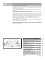
13
Installation & Servicing Instructions Strebel Q-boiler range
14
12
11
38
Condensate tray figure 13.3.g
Step 2: Condensate tray
- remove the plug from the ue gas sensor if present;
- turn the two short clamping rods (11 and 12) ¼ turn and remove them by pulling them
forward; Note the correct turning direction (red indicator, fig. 13.3.h);
- lift the exhaust pipe (13) out of the condensate tray (14);
- press the condensate tray (14) carefully downwards and remove it by pulling it forward;
- replace the gasket between condensate tray and heat exchanger by a new one;
- clean the condensate tray with water and a hard brush;
- check the condensate tray on leaks.
Step 3: Retting is done in reverse order.
Note that all gaskets seals completely.
Make sure that during refitting the clamping rods they are put in the right
position. They should be turned vertical.
Always replace all removed gaskets of dismanteled parts during the
maintenance activities.
Put the boiler into operation and check the O2 (see page 35).
figure 13.3.h
Cylinder (when applicable)
The casing of the cylinder may be cleaned with a damp cloth and a little soap. Do not
use any abrasive or solvent material which could damage the case or ttings.
The following maintenance work has to be carried out by the competent installer.
-
-
-
Inspection of pressure/temperature relief valve and expansion relief valve. Manually
operate each valve by twisting the operating cap, and check if water ows unobstructed
via the tundish to the discharge point. ensure that both valves re-seat satisfactorily.
Check pressure of expansion vessel.
Turn off mains water supply and open nearest hot water tap to depressurise the
secondary water system.
Check the expansion vessel charge pressure gauge at the test point. If the pressure
is below 3.0 bar, top up with suitable air pressure pump.
Complete service section of cylinder commissioning checklist.
In the event that parts require replacement, use only genuine parts supplied by
STREBEL Ltd.
Please contact your installer or STREBEL Ltd. for further details. Contact details can be
found on the back page of this manual.
13.4 Draining the installation
Installation & Servicing Instructions Strebel Q-boiler range
During servicing one of the following items has to be drained:
Central heating system - boiler
The central heating system and boiler can be drained using the fill- and drain valve
installed in the system. If service valves are installed (advised) the boiler can be
drained seperately from the rest of the installation via the drain valves on the service
valves.
39
14
Error indication
A detected error is indicated on the display by means of blocking or error messages. A
distinction should be made between these two messages due to the fact that blocking
can be of a temporary nature, however, error messages are xed lockings. The control
will try its utmost to prevent locking and will temporarily switch off the unit by blocking it.
Hereunder is a list of some messages.
Blocks
with a number in the last 2 positions.
Error
with a number in the last two positions.
Error 00:
Error 02:
Error 04:
Error 05:
Error 18:
Error 19:
Error 28:
Error 69:
Error 80:
FUSE:
Poor ame-forming
no ame-forming. Boiler failed to spark, lite or detect a ame picture.
adjustment or error for voltage interruption
adjustment fault
maximum ow temperature exceeded
maximum return temperature exceeded
number of revolutions not reported back from fan
no or incorrect display
maximum ue gas sensor temperature exceeded
Fuse 24V circuit defective
Installation & Servicing Instructions Strebel Q-boiler range
Block 01:
External safety contact cut off
Block 11:
Maximum 'T of ow and return sensor in central heating has repeatedly been exceeded. During
the block normal operation of the hot water supply is possible. The pump continues to operate at minimum
capacity during the block.
Block 12:
Maximum 'T of ow and return sensor in domestic hot water has repeatedly been exceeded.
During the block normal operation of the central heating installation is possible. During the block the
pump continues to operate at minimum capacity.
Block 60:
Incorrect parameter setting of the minimum or maximum power.
Block 67:
A 'T has been detected between ow and return sensor whereas the burner is not in operation.
After the 'T has disappeared the block will disappear.
Block 80:
Maximum ow temperature T1a has been exceeded (only Q60S). The block will not be cancelled
until the ow temperature has decreased 30K.
Block 81:
The ow sensor T1a (only Q60S) is not connected although it was connected to the control. The
burner is blocked until the ow sensor is reconnected.
Block 82:
The ow sensor has short-circuited (only Q60S), heat requirement blocked and pump capacity at
minimum.
Block 85:
The control has not detected a water ow. The venting cycle is started. If during this cycle water
ow is detected, the venting cycle is ended and the burner is released.
41
Annex A
Technical specifications
STREBEL S-HQ Serie
Q25C
Combi
Q38C
Q51C
Q25S
Q38S
Q51S
Q60S
25
22,5
38
34,2
51
45,9
25
22,5
38
34,2
51
45,9
60
54
31,5
%
109,7
109,1
109,3
109,7
109,1
109,3
109,3
%
97,5
97,4
97,3
97,5
97,4
97,3
97,3
kW
6.0 - 21.9
6.0 - 33.3
8.8 - 44.7
4.4 - 21.9
6.0 - 33.3
8.8 - 44.7
8.8 -52.5
kW
6.8 - 23.9
6.8 - 36.3
9.8 - 48.7
4.9 - 23.9
6.8 - 36.3
9.8 - 48.7
9.8 - 57.3
69
70
70
Boiler type
Input Hs CH
Qn Input Hi CH
Installation & Servicing Instructions Strebel Q-boiler range
Qnw Input Hi DHW
Efficiency class according BED
Efficiency according EN677
(36/30°C part load, Hi)
Efficiency according EN677
(80/60°C full load, Hi)
Modulation range CH
(capacity 80/60°C)
Modulation range CH
(capacity 50/30°C)
Nox class EN483
CO2
Flue gas temp. CH
(80/60°C on full load)
Flue gas temp. CH
(50/30°C on low load)
Gas consumption G20 CH (DHW)
(at 1013 mbar/15°C)
Electr. power consumption max.
Electr. power consumption stand by
Current
Degree of protection acc. EN 60529
Weight (empty)
Width
Height
Depth
Water content CH
Water content DHW
After run time pump CH
After run time pump DHW
PMS Water pressure min./max.
42
PMW Water pressure DHW max.
Flow temperature max.
Pump type
Available pump height CH
DHW flow (at 38°C)
DHW flow (at 60°C)
DHW temperature (T in=10°C)
CE product identification number(PIN)
kW
kW
Solo
5
9
%
°C
68
69
70
31
°C
m3/h
W
W
V/Hz
kg
mm
mm
mm
l
l
min
min
bar
bar
°C
UPER
kPa
l/min
l/min
°C
68
2,38
(3,33)
106
3,62
4,86
2,38
3,62
4,86
5,71
165
150
165
150
168
79
840
79
840
89
1000
53
500
64
660
64
660
5
14
5
14
7
14
106
10
230/50
IPX0D
50
500
680
385
3,5
5
7
7
1
1
1
20-70
22
20-70
20-70
5
1/3
8
20-60
29
13,4
7,5
60
20-70
20
16,6
9,3
60
20-70
85
20-60
32
23,2
13
60
0063BQ3021
Annex B
System water additives
Additive type
Supplier and specications
Max. concentration
Application
Corrosion inhibitors
Sentinel X100 Corrosion resistant
protection agent of CH systems
Kiwa certied
1-2 l/100 litres CH water content
Aqueous solution of organic and
inorganic agents preventing corrosion and scale forming
Anti-freeze
Kalsbeek
50% w/w
Monopropyleneglycol / propane1,2-diol
+ inhibitors
AKWA-Colpro
KIWA-ATA
Nr.
2104/1
Anti-freeze
Tyfocor L
Monopropyleneglycol / propane1,2-diol
+ inhibitors
50% w/w
Anti-freeze
Sentinel X500
Monopropyleneglycol + inhibitors
Kiwa certied
20-50% w/w
Anti-freeze
Sentinel X300
Solution of phosphate, organic heterocyclic compounds, polymers
and organic bases
Kiwa certied
1 litre / 100 litres
For new CH installations Removes
oils/grease and ow control agents
Sentinel X400
Solution of synthetic organic polymers
1-2 litres / 100 litres
For cleaning existing CH-installations Removes sediments.
Sentinel X800 Jeto
Aqueous emulsion of dispersants,
moistening agents and inhibitors
1-2 litres / 100 litres
For cleaning new and existing CHinstallations Removes iron and
lime-related sediments.
System cleaners
Installation & Servicing Instructions Strebel Q-boiler range
When the lling water requirements as referred to in chapter Water Quality have been met, certain additives are allowed for the below mentioned applications and related dosage. Warranty on STREBEL delivered installation products
expires, if these additives and concentrations are not used in accordance with this annex.
43
Annex C
Dimensions
C
B
B
F
D
D
50
E
Minimal 250mm
ceiling
10
wall
wall
wall
A
RQP
G
H
G
J
H
K
J
S
T
U
K
L
N
P
Installation & Servicing Instructions Strebel Q-boiler range
Boiler type
44
A
B
C
D
E
F
G
H
J
K
L
M
N
O
P
Q
R
S
T
U
Height
Width
Depth
Left side / flue gas connexion
Centre to centre flue gas and air supply
Back / flue gas connexion
Left side / gas pipe
Left side / flow pipe
Left side / return pipe
Left side / condensate pipe
Left side / expansion pipe
Left side / return pipe DHW
Left side / cold water pipe
Left side / hot water pipe
Pipe length of g*
Pipe length of c*
Pipe length of a; r*
Back / centre of pipe c*
Back / centre of pipe g*
Back / centre of pipe a and r*
STREBEL S-HQ Serie
Q51C
Q25S
Q38S
Q25C
Q38C
mm
mm
mm
mm
mm
mm
mm
mm
mm
mm
mm
680
840
385
335
120
270
65
185
285
370
430
680
840
385
335
120
270
65
185
285
370
430
680
1000
385
495
120
270
65
185
445
530
590
mm
725
765
18
40
60
25
40
50
725
795
18
40
60
25
40
50
885
955
18
40
60
25
40
50
mm
mm
mm
mm
mm
mm
Q51S
Q60S
680
500
385
335
120
270
65
185
285
370
680
500
385
335
120
270
65
185
285
370
680
660
385
495
120
270
65
185
445
530
680
660
385
495
120
270
65
185
445
530
18
40
60
25
40
50
18
40
60
25
40
50
18
40
60
25
40
50
18
40
60
25
40
50
a
r
c
g
Boiler type
g
a
r
c
e
k
h
d
Concentric flue system
Parallel flue system
Gas pipe
Flow pipe
Return pipe
Condensate pipe
Expansion pipe
Cold water pipe
Hot water pipe
Return pip DHW
mm
mm
mm
mm
mm
mm
mm
mm
mm
a
r
c e
k
Q25C
Q38C
STREBEL S-HQ Serie
Q51C
Q25S
Q38S
80/125
optional
3/4"Rp
28
28
24
22
15
15
80/125
optional
3/4"Rp
28
28
24
22
15
15
80/125
optional
1/2"Rp
35
35
24
22
15
15
80/125
optional
3/4"Rp
28
28
24
80/125
optional
3/4"Rp
28
28
24
w
Q51S
Q60S
80/125
optional
1/2"Rp
35
35
24
80/125
optional
1/2"Rp
35
35
24
Installation & Servicing Instructions Strebel Q-boiler range
g
45
Annex D
Installation examples
D.1 Radiator installation without thermostatic radiator valves
Installation & Servicing Instructions Strebel Q-boiler range
BP
46
A Boiler:
A0
A1
A4
tra
BP
Connection terminal STREBEL S-HQ
BrainQ thermostat
RSC
Outside sensor
ARV12
Thermostatic radiator valve
Automatic by-pass
Use alway a by pass in combination with thermostatic radiator valves.
Low loss header required for Q51 and Q60.
A Boiler:
A0
A4
A9
A10
B Cylinder:
B3
B5
C Direct zone:
C6
D Mixing zone:
D2
D5
D6
Connection terminal STREBEL S-HQ
Outside sensor
ARV12
MadQ zone coltroller
23BC
Connection terminal MadQ built in
Cylinder sensor
Three-way valve cylinder
Pump direct zone
Flow sensor mixing zone
Three way valve mixing zone
Pump mixing zone
See also the installation manual MadQ Zone controller.
230V~
Installation & Servicing Instructions Strebel Q-boiler range
D.2 Radiator installation with underfloor heating zone
47
Annex E
Declaration of conformity
CE DECLARATION OF CONFORMITY
Hereby declares ATAG Verwarming Nederland BV that,
the condensing boiler types: ATAG
Q25S
Q38S
Q51S
Q60S
Q25C
Q38C
Q51C
are in conformity with the provisions of the following EC Directives, including all amendments,
and with national legislation implementing these directives:
Directive
Gas Appliance Directive
2009/142/EC
(ex.90/396/EEG)
Efciency Directive
Low Voltage Directive
92/42/EEC
2006/95/EG
EMC Directive
2004/108//EG
Used standards
EN483: 1999,A2 ;2001C1 ;2006,A4 ;2007
EN50165: 1997
EN677: 1998
EN50165: 1997
EN60335-1: 1994
EN61000-3-2: 2000,A1 ;2001,A2 ;2005
EN61000-3-3: 1995,2006
EN55014-1: 1993;A1;2001,A2;2002
EN50165: 1997,A1;2001
EN55014-2: 1997,A1;2001
Report numbers
GAD
177021
Installation & Servicing Instructions Strebel Q-boiler range
ATAG Q
48
ED
177021
LVD
177021
EMC D
178195-EMC
and that the products are in conformity with EC type-examination certicate number E0430,
as stated by KIWA-Gastec Certication BV, Apeldoorn, The Netherlands.
Date
: 2-11-2010
Signature
:
Full name
:
C. Berlo
CEO
Installation & Servicing Instructions Strebel Q-boiler range
Annex F
Kiwa certificate
49
Failure to install and commission according to the manufacturer’s instructions and complete this Benchmark Commissioning Checklist will invalidate the warranty. This
does not affect the customer’s statutory rights.
Installation & Servicing Instructions Strebel Q-boiler range
If yes, and if required by the manufacturer, has a water scale reducer been fitted?
CONDENSING BOILERS ONLY
The condensate drain has been installed in accordance with the manufacturer’s instructions and/or BS5546/BS6798
Yes
If the condensate pipe terminates externally has the pipe diameter been increased and weatherproof insulation fitted?
Yes
50
Service Record
It is recommended that your heating system is serviced regularly and that the appropriate Service Interval Record is completed.
Service Provider
Before completing the appropriate Service Record below, please ensure you have carried out the service as described in the
manufacturer’s instructions.
Always use the manufacturer’s specified spare part when replacing controls.
Date:
Service 2
Date:
Engineer Name:
Engineer Name:
Company Name:
Company Name:
Telephone No.
Telephone No.
Gas Safe Register No.
Gas Safe Register No.
Comments:
Comments:
Signature:
Signature:
Service 3
Date:
Service 4
Date:
Engineer Name:
Engineer Name:
Company Name:
Company Name:
Telephone No.
Telephone No.
Gas Safe Register No.
Gas Safe Register No.
Comments:
Comments:
Signature:
Signature:
Service 5
Date:
Service 6
Date:
Engineer Name:
Engineer Name:
Company Name:
Company Name:
Telephone No.
Telephone No.
Gas Safe Register No.
Operative ID No.
Comments:
Comments:
Signature:
Signature:
Service 7
Date:
Service 8
Date:
Engineer Name:
Engineer Name:
Company Name:
Company Name:
Telephone No.
Telephone No.
Gas Safe Register No.
Gas Safe Register No.
Comments:
Comments:
Signature:
Signature:
Service 9
Date:
Service 10
Date:
Engineer Name:
Engineer Name:
Company Name:
Company Name:
Telephone No.
Telephone No.
Gas Safe Register No.
Gas Safe Register No.
Comments:
Comments:
Signature:
Signature:
Installation & Servicing Instructions Strebel Q-boiler range
Service 1
51
This renewed publication cancels all previous installation instructions. The company reserves the right to change the specications and dimensions without prior notice.
S T R E B E L LT D . • 1 F, A l b a n y p a r k i n d u s t r i a l e s t a t e • F r i m l e y r o a d , C a m b e r l e y • S u r r e y G U 1 5 2 P L
Telephone: (01276) 685422 • Fax: (01276) 685405 • E-mail: [email protected] • Internet: www.strebel.co.uk
E. & O. E.