1
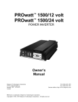
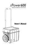
DC to AC
POWER INVERTER
OWNER’S MANUAL
Table of Contents
1 Introduction ................................................................................ 1
2 How Your Portawattz TM 3000 Inverter Works ............................... 1
2.1 Principle of Operation ....................................................................................... 1
2.2 Portawattz TM 3000 Inverter Output Waveform ................................................ 2
3 Physical Layout of the Portawattz TM 3000 Inverter ..................... 3
4 Quick Operational Check (optional) .......................................... 5
4.1 DC Power Source .............................................................................................. 5
4.1.1. Battery ........................................................................................................ 5
4.1.2. DC Power Supply ........................................................................................ 5
4.2 DC Cables ......................................................................................................... 5
4.3 Test Loads .......................................................................................................... 7
4.4 Connections ...................................................................................................... 7
5 Permanent Installation ............................................................... 9
5.1 Where to Install .................................................................................................. 9
5.2 Battery .............................................................................................................. 10
5.2.1 Battery type ................................................................................................ 10
5.2.2. Battery Sizing ............................................................................................ 11
5.2.3. Using Multiple Batteries ............................................................................. 13
5.2.4. Battery Tips ............................................................................................... 14
5.2.5. Alternators and Charging Systems ............................................................. 15
5.3 Battery Cables ................................................................................................. 16
5.4 Connections .................................................................................................... 18
5.4.1 AC Wiring ................................................................................................... 18
5.4.2 Ground Wiring ............................................................................................ 18
5.4.3 DC Wiring ................................................................................................... 19
6 Operation .................................................................................. 2 0
6.1 Front Panel Controls and Indicators ............................................................. 20
6.1.1. ON/OFF Switch ......................................................................................... 20
6.1.2. Remote ON/OFF Jack ............................................................................... 20
6.1.3. Battery Voltage Indicator ............................................................................ 21
6.1.4. Battery Current Indicator ............................................................................ 21
6.1.5. OVERTEMP Indicator ................................................................................. 21
6.1.6 OVERLOAD Indicator .................................................................................. 21
6.1.7 ALARM Indicator ......................................................................................... 22
Portawattz is a trademark of Statpower Technologies Corporation. Copyright © 1998,1999 Statpower
Technologies Corporation. All rights reserved.
6.2 Operating Limits .............................................................................................. 22
6.2.1. Power Output ............................................................................................ 22
6.2.2. Input Voltage ............................................................................................. 22
7 Accessories .............................................................................. 2 3
7.1 Remote ON/OFF switch option ..................................................................... 23
7.2 DC Box-Lug connectors ................................................................................. 23
8 Troubleshooting ........................................................................ 2 4
8.1 Common Problems ......................................................................................... 24
8.1.1. Buzz in Audio Systems .............................................................................. 24
8.1.1. Television Interference ............................................................................... 24
8.2 Troubleshooting Guide ................................................................................... 25
9 Maintenance ............................................................................. 2 6
10 Warranty .................................................................................. 2 6
10.1 Warranty Terms .............................................................................................. 26
10.2 To Obtain Warranty Service .......................................................................... 27
11 Specifications ......................................................................... 2 9
11.1 Electrical Performance ................................................................................. 29
11.2 Dimensions .................................................................................................... 29
12. Other Products from Statpower ............................................. 3 0
1 Introduction
Your new Portawattz 3000 inverter is a member of the most advanced line
of DC to AC inverters available today. It will give you years of dependable
service in your boat, RV, service vehicle or remote home.
To get the most out of your Portawattz 3000, it must be installed and used
properly. Please read the installation and operating instructions in this
manual carefully before installing and using your Portawattz 3000. Pay
special attention to the CAUTION and WARNING statements in this
manual and on the unit. CAUTION statements identify conditions or
practices which could result in damage to your unit or to other equipment.
WARNING statements identify conditions or practices that could result
in personal injury or loss of life.
2 How Your PortawattzTM 3000 Inverter Works
An inverter is an electronic device that converts low voltage DC (direct
current) electricity from a battery or other power source to standard 115
volt AC (alternating current) household power. In designing the Portawattz
3000, Statpower has used power conversion technology previously
employed in computer power supplies to give you an inverter that is
smaller, lighter, and easier to use than inverters based on older technology.
2.1 Principle of Operation
The Portawattz 3000 converts power in two stages. The first stage is
a DC-to-DC converter which raises the low voltage DC at the inverter
input to 145 volts DC. The second stage is the actual inverter stage.
It converts the high voltage DC into 115 volts, 60 Hz AC.
The DC-to-DC converter stage uses modern high frequency power
conversion techniques that eliminate the bulky transformers found in
inverters based on older technology. The inverter stage uses
advanced power MOSFET transistors in a full bridge configuration.
This gives you excellent overload capability and the ability to operate
tough reactive loads like lamp ballasts and induction motors.
1
Figure 1 - Principle of Operation
2.2 PortawattzTM 3000 Inverter Output Waveform
The AC output waveform of the Portawattz 3000 is called a “quasisine wave” or a “modified sine wave”(see Figure 2). It is a stepped
waveform that is designed to have characteristics similar to the sine
wave shape of utility power. A waveform of this type is suitable for
most AC loads, including linear and switching power supplies used
in electronic equipment, transformers, and motors. This waveform
is much superior to the square wave produced by many other DC to
AC inverters.
Figure 2.
Modified Sine Wave
The modified sine wave produced by the Portawattz 3000 is designed
to have an RMS voltage of 115 volts, the same as standard household
power. Most AC voltmeters (both digital and analog), are sensitive
to the average value of the waveform rather than the RMS value.
They are calibrated for RMS voltage under the assumption that the
2
waveform measured will be a pure sine wave. These meters will not
read the RMS voltage of a modified sine wave correctly. They will
read about 2 to 20 volts low when measuring the output of the
Portawattz 3000. For accurate measurement of the output voltage,
a true RMS reading voltmeter, such as a Fluke 87, Fluke 27, Tektronix
DMM 249, or B&K Precision Model 391, must be used.
CAUTION!
RECHARGEABLE APPLIANCES. DO NOT USE THE
PORTAWATTZ TM 3000 WITH THE EQUIPMENT LISTED BELOW.
Certain rechargers for small nickel cadmium batteries can be damaged if connected
to the unit. Two particular types of equipment are prone to this problem:
1) small battery operated appliances such as flashlights, razors,
and night lights that can be plugged directly into an AC
receptacle to recharge.
2) certain battery chargers for battery packs used in hand power
tools. These chargers will have a warning label stating
dangerous voltages are present at the battery terminals.
This problem does not occur with the vast majority of battery operated equipment.
Most of this equipment uses a separate charger or transformer that is plugged into
the AC receptacle and produces a low voltage output. If the label on the AC adapter
or charger states that the adapter or charger produces a low voltage AC or DC
output (less than 30 volts), the Portawattz will have no trouble powering this charger
or adapter safely.
3 Physical Layout of the PortawattzTM 3000 Inverter
Your inverter was designed with a logical and efficient back to front flow in
mind. Battery power is applied to the large terminals on the rear of the
unit and flows forward to the AC receptacles on the front panel. All of the
indicators, controls, and output connections that you will need to access
after a permanent installation are conveniently located on the front panel
(see Figure 3). See Section 6.1, Front Panel Controls and Indicators, for
a detailed explanation of the functions of the various controls and indicators
on your Portawattz 3000.
Forced air cooling also flows in the same direction, with the fan drawing
air in from the rear and blowing it out through the vents on the front panel.
NOTE: It is important to provide an adequate airspace around these
surfaces to allow for convection cooling. See Section 5.1 for installation
notes.
3
Figure 3 - Front and Rear panel
4
4 Quick Operational Check (optional)
This section will give you the information you need if you wish to quickly
hook-up your Portawattz 3000 and check its performance before going
ahead with permanent installation. You will need the following:
a) a 12 volt DC power source
b)two cables to connect the DC power source to the Portawattz 3000
c)a test load of 100 - 1000 Watts.
d)a line cord to connect the test load to the AC receptacle.
4.1 DC Power Source
The power source must provide between 11 and 15 volts DC and
must be able to supply sufficient current to operate the test load. As
a rough guide, divide the wattage of the test load by 10 to obtain the
current (Amps) the power source must deliver (see example).
4.1.1. Battery
Use a fully-charged 12 volt (nominal) battery that can deliver
the required current while maintaining
its voltage above 11 volts. A fullyExample:
charged 12 volt automobile battery
Test load is rated at 250 watts.
is capable of delivering up to 50
Power supply must be able to deliver
amperes without an excessive
250 ÷ 10 = 25 Amps
voltage drop.
4.1.2. DC Power Supply
Use a well regulated DC power supply that has an output
voltage between 11 volts and 15 volts and can deliver the
required current. If the supply is adjustable, make sure that
the output voltage is adjusted to be between 11 volts and 15
volts. The inverter may shut down if the voltage is outside these
limits and may be damaged if the voltage is above 16 volts.
Also ensure that any current limit control is set so that the power
supply can deliver the required current.
4.2 DC Cables
Your cables must be as short as possible and large enough to handle
the required current. This is to minimize the voltage drop between
the power source and the inverter when the inverter is drawing large
currents from the power source. If the cables introduce an excessive
voltage drop, the inverter may shut down when drawing higher
currents because the voltage at the inverter drops below 10 volts.
5
Also, longer and/or thinner cables will reduce the efficiency of the
overall system, since excessive power will be dissipated in the cabling.
For temporary operation at
reduced power levels, the
guidelines listed in Table 1 may
be followed, or you can use the
cable sizes in Table 6.
Ideally, the cables should be no
more than 4 ft (1.5m) long. See
table 2 for a pictorial
representation of the wire
gauges.
Max. Test Load
Power
Consumption for
Short Term Test
Min. Cable Size
(Copper material
only)
100 Watts
#16 AWG
250 Watts
#12 AWG
500 Watts
#8 AWG
Table 1 - Temporary Load Wire Gauge
Chart
CAUTION!
DO NOT operate your inverter for more than 5 minutes or at a higher power
using these cable sizes. Refer to table 6.
Strip approximately 1/2” (1.25cm) of insulation from the ends of the
cables being connected to the inverter. Attach 5/16” ring terminals
to the ends of the wires to be attached to the DC terminals on the
Portawattz 3000. The ring terminals should be crimped with a proper
crimping tool.
Another option is to use Ilsco, or equivalent, box-lug terminals
(available at electrical parts suppliers). The bare cable end can then
be inserted into the lug terminal.
The other ends of the cables, which are connected to the power
source, must be terminated with lugs or other connectors that allow
a secure, low resistance connection to be made to the power source.
For instance, if the power source is a battery, the cables must be
terminated with battery terminals that clamp to the posts on the
battery.
A solid, low resistance connection to the DC power
source is essential for proper operation.
6
4.3 Test Loads
Use only equipment rated for 110 - 120 volt,
60 Hz AC operation that has a power
consumption of 500 watts or less. We
recommend that you start with a relatively
low power load, such as a 100 watt lamp,
to verify your test set-up before trying high
power loads.
4.4 Connections
Follow the connection sequence described
below:
ALPHA Neoprene
Welding Cable
Wire Size
(AWG)
Overall Outside
Diameter
(inches/mm)
#6
0.35/8.89
#4
0.42/10.70
#2
0.48/12.19
#1
0.52/13.21
#1/0
0.58/14.77
#2/0
0.64/16.26
#3/0
0.70/17.78
#4/0
0.82/20.83
STEP 1 - Ensure the ON/OFF switch on Table 2 - Wire size
the Portawattz 3000 is in the
OFF position. If the power
source is a DC power supply, switch it off as well.
Chart
Figure 4. Connections to the Portawattz 3000
STEP 2 - Connect the DC cables to the power input
terminals on the rear panel of the Portawattz 3000.
The Red terminal is positive (+) and the Black
terminal is negative (-). Tighten the wire
connections securely. (see figure 4).
STEP 3-
Connect the cable from the negative (Black)
terminal of the Portawattz 3000 to the negative
terminal of the power source (battery or power
supply). Make a secure connection.
CAUTION!
Loose connectors result in excessive voltage drop and may cause
overheated wires and melted insulation.
7
STEP 4 - Before proceeding further, carefully check that the
cable you have just attached connects the
negative terminal of the Portawattz 3000 to the
negative output terminal of the power source.
Power connections to the Portawattz 3000 must
be positive to positive and negative to negative.
CAUTION!
Reverse polarity connection (positive to negative) will blow the fuses in the
Portawattz 3000 and may permanently damage the unit. Damage caused by
reverse polarity connection is not covered by your warranty.
WARNING!
You may observe a spark when you make the following connection since current
may flow to charge capacitors in the Portawattz 3000. Do not make this
connection in the presence of flammable fumes. Explosion or fire may result.
STEP 5 - Connect the cable from the positive (Red terminal
of the Portawattz 3000 to the positive terminal of
the power source. Make a secure connection.
STEP 6 - If you are using a DC power supply as the power
source, switch it on. Set the ON/OFF switch on
the Portawattz 3000 to the ON position. Check
the meters and indicators on the front panel of
the Portawattz 3000. The battery voltage indicator
should indicate 11 to 14 volts, depending on the
voltage of the power source. If it does not, check
your power source and the connections to the
Portawattz 3000. The other indicators should be
off.
STEP 7 - Set the Portawattz 3000 ON/OFF switch to the OFF
position. The indicator lights may blink and the
internal alarm may sound momentarily. This is
normal. Plug in the test load now, but make sure
that it is first switched off.
STEP 8 - Set the Portawattz 3000 ON/OFF switch to the ON
position and turn the test load on. The Portawattz
3000 should supply power to the load. If it does
not, refer to the troubleshooting section of this
manual. If you plan to measure the output voltage
of the Portawattz 3000, refer to Section 2.2 of this
manual.
8
5 Permanent Installation
5.1 Where to Install
The Portawattz 3000 should be installed in a location that meets the
following requirements:
• Dry - Do not allow water to drip or splash on the Portawattz
3000.
•Cool - Ambient air temperature should be between 0ºC and
25ºC (32ºF and 77ºF). The cooler the better.
• Ventilated - Ensure that the unit is in a compartment that is
ventilated, and that you allow at least 1 inch
(2.5cm) of clearance around the Portawattz 3000
for air flow. Ensure that ventilation openings on
the front and rear of the unit are not obstructed.
• Safe - Do not install the Portawattz in the same compartment
as batteries or in any compartment capable of storing
flammable liquids such as gasoline (see warning
below).
• Close to Battery - Install as close to the battery as possible in
order to minimize the length of cable
required to connect the inverter to the
battery, but not in the same compartment.
It is better and cheaper to run longer AC
wires than longer DC cables, because of
the much lower currents in the AC wires.
CAUTION!
To reduce fire hazard, do not cover or obstruct ventilation openings. Do not
install the Portawattz 3000 in a zero-clearance compartment. Overheating
may result.
WARNING!
This equipment contains components which tend to produce arcs or sparks.
To reduce risk of fire or explosion do not install in compartments containing
batteries or flammable materials or in locations which require ignition protected
equipment.
Mount the Portawattz on a flat surface using the mounting flanges on
the front and rear panels. Mounting hardware should be corrosion
resistant and #10 or larger. The Portawattz may be mounted
horizontally or vertically.
9
5.2 Battery
The battery you use strongly affects the performance you can expect
from your Portawattz 3000. It is important to connect the Portawattz
3000 to the correct size and type of battery. The following information
will help you select the appropriate batteries for your application.
5.2.1 Battery type
The lead-acid battery which is probably most familiar is the
starting battery in your automobile. An automotive starting
battery is designed to deliver a large amount of current for a
short period of time (so it can start your engine). Only a small
portion of the battery’s capacity is used when starting the engine
and it is quickly recharged by the running engine. It is not
designed for repeated charge-discharge cycles where the
battery is almost completely discharged and then recharged.
If it is used in this kind of deep discharge service, it will wear
out very rapidly.
Deep-cycle lead-acid batteries are designed for deep discharge
service where they will be repeatedly discharged and
recharged. They are marketed for use in recreational vehicles,
boats, and electric golf carts so you may see them referred to
as RV batteries, marine batteries, or golf cart batteries.
Figure 5 - Configuration for Medium-Duty Applications
For most applications of the Portawattz 3000, Statpower
recommends that you use one or more deep-cycle batteries
that are separated from the starting battery in your vehicle by a
battery isolator. A battery isolator is a solid-state electronic circuit
which allows equipment to be operated from an auxiliary battery
without danger of discharging the vehicle’s starting battery.
During vehicle operation, the battery isolator automatically
directs the charge from the alternator to the battery requiring
10
the charge. Battery isolators can be obtained at marine and RV
dealers and most auto parts stores.
If your application involves relatively low power loads (i.e. power
consumption of 300 watts or less) and relatively short operating
times before recharging (one hour or less), you may connect
the Portawattz 3000 directly to the vehicle starting battery.
Figure 6. Connection for Light-Duty Applications
CAUTION!
The Portawattz 3000 must be connected only to batteries with a nominal output
voltage of 12 volts. The Portawattz 3000 will not operate from a 6 volt battery,
and will be damaged if it is connected to a 24 volt battery.
5.2.2. Battery Sizing
There are a number of different standards for rating battery
energy storage capacity. Automotive starting batteries are
normally rated by cranking amps. This is not a relevant rating,
for continuous use. Deep-cycle batteries are rated either by
reserve capacity in minutes or by ampere-hour capacity.
Battery reserve capacity is a measure of how long a battery
can deliver a certain amount of current - usually 25 amperes.
For instance, a battery with a reserve capacity of 180 minutes
can deliver 25 amperes for 180 minutes before it is completely
discharged.
Ampere-hour capacity is a measure of how many amperes a
battery can deliver for a specified length of time - usually 20
hours. For example, a typical marine or RV battery rated for
100 ampere-hours can deliver 5 amperes for 20 hours (5
amperes x 20 hours = 100 amp-hrs).
Actual battery capacity decreases as discharge current
increases. A battery rated at 100 ampere-hours which can
deliver 5 amperes for 20 hours, may deliver 20 amperes for
11
only 4 hours, resulting in an actual capacity of 80 ampere-hours.
For this reason, it is difficult to compare rated ampere-hour
capacity with battery reserve capacity. For example a battery
with a reserve capacity of 180 minutes has the following
calculated ampere-hour capacity:
However its actual ampere-hour rating will be closer to 100
ampere-hours because it is
rated at the discharge current
180 min.÷ 60 = 3 hrs
required to get 20 hours of
Therefore...
operation (about 5 amperes).
To determine the battery
3 hr. x 25 amps = 75 amp-hrs
capacity you require, follow
these steps:
STEP 1 - For each piece of equipment you will be operating
from the Portawattz 3000, determine how many
watts it consumes. This can normally be found
on a label on the product. If only the current draw
is given, multiply the current draw by 115 to get
the power consumption in watts.
STEP 2 - For each piece of equipment you will be operating
from the Portawattz 3000, estimate how many
hours it will operate between battery charging
cycles.
STEP 3 - Calculate total watt-hours of energy consumption,
total hours running time, and average power
consumption as in the following example:
Equipment
Power
Watt Hours
Consumption Operating time
( Power x Operating Time)
(Watts)
TV & VCR
115
3 Hrs.
Sewing Machine
150
1 Hr.
150
Waterpik
90
0.25 Hrs. (15 Min.)
22.5
Blender
300
0.25 Hrs. (15 Min.)
75
Coffee Maker
750
0.3 Hrs. (18 Min.)
225
Coffee Grinder
100
0.2 Hrs. (12 Min.)
20
Microwave Oven
1500
0.5 Hrs. (30 Min.)
750
Washing Machine
1500
0.5 Hrs. (30 Min.)
750
6.0Hrs.
2337.5 watt-hours
TOTAL
345
Table 3
STEP 4 - Using Table 3, find the battery size that will give
you the required operating time at the calculated
average power consumption. For instance, from
the example below, the required operating time is
6 hours and the average power consumption is
12
387 watts. From the chart, the smallest battery
size which will give more than 6 hours of operation
at a power level between 300 and 400 watts are
two 400 amp-hr. batteries in parallel, which offers
between 10 and 12 hours of operating time.
Average Power Consumption
= 2337 watt-hrs ÷ 6 hours
= 390 watts
12 volt Ampere-Hours Consumed
Inverter
Ouput
Power
(Watts)
= Watt-hours ÷ 10
= 2337 ÷ 10
= 234 ampere-hours
Battery Size
Typical Load
BCI Group Size
22NF
24
Reserve
Capacity
90 min.
27
8D
AMP-Hrs.
50
75
100
200
400
20 Hrs.
40 Hrs.
80 Hrs.
140 min. 180 min. 400 min.
Dual 8D's
900 min.
50
Stereo System
Operating Time
9 Hrs.
14 Hrs.
100
19" Colour TV
Operating Time
4 Hrs.
6 Hrs.
10 Hrs.
20 Hrs.
40 Hrs.
200
Computer System
Operating Time
2 Hrs.
3 Hrs.
4.5 Hrs.
10 Hrs.
20 Hrs.
300
Blender
Operating Time
1.3 Hrs.
2.2 Hrs.
3 Hrs.
6 Hrs.
12 Hrs.
400
Power Drill
Operating Time
1 Hr.
1.5 Hrs.
2 Hrs.
4.5 Hrs.
10 Hrs.
600
Small Coffee Maker
Operating Time
N.R.
N.R.
1 Hr.
2.5 Hrs.
6 Hrs.
800
Small Microwave
Operating Time
N.R.
N.R.
N.R.
1.5 Hrs.
4 Hrs.
1000
Toaster
Operating Time
N.R.
N.R.
N.R.
1 Hr.
3 Hrs.
1500
Full Size Microwave
Operating Time
N.R.
N.R.
N.R.
0.5 Hrs.
2 Hrs.
2500
Hair Dryer & Washing
Machine
Operating Time
N.R.
N.R.
N.R.
0.2 Hrs.
0.8 Hrs.
N.R. = Not Recommended
Table 4 - 12 Volt Battery Sizing Chart
When sizing your battery, be conservative. More capacity is
better since you will have more reserve capacity, and your
battery won’t be discharged as deeply. Battery life is directly
dependent on how deeply the battery is discharged. The
deeper the discharge, the shorter the battery life. Ideally, the
number of ampere-hours consumed by your loads before
recharging the battery should be no more than 50% of the
battery’s rated capacity.
5.2.3. Using Multiple Batteries
To obtain sufficient battery capacity you may need to use more
than one battery. Two identical batteries can be connected +
to + and - to - in a parallel system that doubles capacity and
maintains the voltage of a single battery. Do not connect
batteries from different manufacturers, or with different amp-hr
ratings, in parallel - decreased battery life may result (see Figure
7).
13
If you are using different
batteries, or need to use more
than two batteries, we
recommend that you set up
two separate battery banks
and use them alternately.
Battery selector switches are
Figure 7. Parallel Batteries
available from marine and RV
dealers which allow you to
select between two banks of batteries, or use both in parallel,
or disconnect both from the load (see Figure 8).
Figure 8. Configuration for heavy-duty Applications
5.2.4. Battery Tips
1. With the exception of sealed batteries, lead-acid batteries
emit hydrogen and oxygen gases, and sulfuric acid fumes
when recharging. Vent the battery compartment to prevent
accumulation of these gases, and do not install electronic
or electrical equipment in the battery compartment. Do
not smoke or carry an open flame when working around
batteries.
14
2. The capacity of lead-acid batteries is temperature sensitive.
Battery capacity is rated at 25ºC (77ºF). At -20ºC (0ºF) the
ampere-hour capacity will be about half the rated capacity.
3. Do not leave batteries in a discharged state for more than a
day or two. They will undergo a chemical process called
sulfation which can permanently damage the batteries.
Also, batteries will self-discharge over a period of 3 to 6
months, so they should be periodically recharged even if
they are not being used.
4. If your batteries are not the “maintenance-free” type, check
the electrolyte fluid level at least once a month. Use only
distilled water to replenish the electrolyte fluid. Excessive
fluid loss is a sign of overcharging.
5. Connections to battery posts must be made with permanent
connectors that provide a reliable, low resistance
connection. Do not use “alligator” clips. Clean the
connections regularly and prevent corrosion by using an
insulating spray coating or Vaseline.
6. Battery state of charge can be
measured with a hydrometer or,
more easily, with a voltmeter. Use
a digital voltmeter that can display
tenths or hundredths of a volt
when measuring 10 to 30 volts.
Make your measurements after
the (12 volt) battery has not been
charged or discharged for several
hours. For a deep-cycle battery
at 25ºC (77ºF), refer to table 5.
Battery
Voltage
State of
Charge
12.7-12.9
100%
12.5-12.6
80%
12.3-12.4
60%
12.1-12.2
40%
11.9-12.0
20%
Table 5 - Battery Charge
State.
5.2.5. Alternators and Charging Systems
A good charging system is important for the health of your
batteries. Poor recharging methods can quickly damage your
batteries. When possible, recharge your batteries when they
are about 50% discharged. This will give you much longer
battery cycle life than recharging when the batteries are almost
completely discharged. The StatpowerTRUECHARGETM family
of battery chargers are designed to maximize your battery’s
performance and useful life (see your Statpower dealer for more
details).
The charging system should be capable of delivering a charging
current equal to 25% of the ampere-hour capacity of your
battery. For instance, if you have a 200 ampere-hour battery,
the charging system should be able to deliver 50 amperes.
The charging system must also be able to charge each 12 volt
15
battery up to approximately 14.4 volts and then drop back to a
“float” voltage of 13.5 to 14 volts (or shut off).
A typical engine alternator may not be able to meet these
requirements if large capacity batteries are used. Alternators
are typically rated for the current they can deliver when they
are cold. In actual use, alternators heat up and their output
current capability drops by as much as 25%. Thus standard
alternators with ratings of 40 amperes to 105 amperes will only
deliver a maximum of 30 to 80 amperes in actual use and will
deliver even less as battery voltage rises. Many alternators
cannot produce more than 13.6 volts when they are hot. As a
result, a standard alternator may not be able to charge a large
battery quickly and completely.
One solution is to install an alternator controller that will bypass
the voltage regulator and boost the alternator’s output voltage
during charging. This will increase the alternator’s charging
rate at higher battery voltages and ensure more rapid and
complete charging. Alternator controllers are available from
marine product dealers.
Another solution is to install a high-output alternator. Heavyduty alternators rated from 100 amperes to 140 amperes are
available from RV and marine dealers, and auto parts suppliers.
These alternators are designed to directly replace standard
alternators but produce the higher current and higher voltage
required to charge multiple battery systems.
When recharging from AC power, use a good quality marine
battery charger or RV converter that meets the requirements
specified above. Do not use chargers intended for occasional
recharging of automotive starting batteries; these chargers are
not intended for continuous use.
Your batteries may also be recharged from alternative energy
sources such as solar panels, wind, or hydro systems. Make
sure that you use the appropriate battery charge controller for
your energy source.
Do not operate the Portawattz 3000 directly from a charging
source such as an alternator or solar panel. The Portawattz
must be connected to a battery or a well-regulated, high-current
DC power supply to work properly.
5.3 Battery Cables
Proper wire and wiring is very important for the safe and proper
operation of the Portawattz 3000. Because the Portawattz 3000 has
a low voltage, high current input, low resistance wiring between the
16
battery and the Portawattz 3000 is essential to deliver the maximum
amount of usable energy to your load. Don’t waste the investment
you have made in batteries and a highly efficient inverter by using
undersized wires.
Use only copper wire. Aluminum wire has about 1/3 more resistance
than copper wire of the same size and it is more difficult to make a
good, low-resistance connection. We recommend 2 x #1AWG or 1
x 3/0AWG copper cable (90ºC insulation rating), as the minimum
size for connecting between the battery and the Portawattz 3000.
Keep the cable as short as possible,
(Max. 10 ft./3 m). This will keep the
overall system running at peak
Lower efficiency means
shorter run-times
efficiency, and will keep the voltage
drop between the battery and the unit
to a minimum.
If the battery cables introduce an excessive voltage drop, the inverter
may shut down when drawing higher currents because the voltage
at the inverter drops below 10 volts. If you must use longer cables,
then refer to Table 6 to decide on the next best size.
Max. Length
of Cable
(ft./m)
Min. Cable
Size if using
Single Cables
Min. Cable
Size if using
Double Cables
10/3
No. 3/0 AWG
2 x No. 1 AWG
15/4.6
250 MCM
2 x No. 2/0 AWG
20/6.1
400 MCM
2 x No. 3/0 AWG
Table 6: DC Cable Sizes (for voltage drop less than
0.5Vdc total - based on 90ºC cable)
CAUTION!
Use cable rated at 90ºC. For cable rated below 90ºC or run in conduit, refer to
applicable codes or standards for your application. Based on Table 1 of the
Canadian Electrical Code, Part 1, and on Table 310-17 of the U.S. National Electrical
Code (NFPA 70), 1993.
Strip approximately 1/2” (12.5mm) of insulation from the ends of the
DC cables being connected to the inverter. Attach 5/16” ring terminals
to the ends of the wires to be attached to the DC terminals on the
Portawattz 3000. The ring terminals should be crimped with a proper
crimping tool.
Another option is to use Ilsco or equivalent box-lug terminals,
(available at electrical parts suppliers). The bare cable end can then
be inserted into the lug terminal.
17
The other ends of the cables, which are connected to the battery,
must be terminated with battery terminals that clamp to the posts on
the battery.
Do not tin the cable ends with solder. Doing so will
result in a poor long-term connection.
A solid, low resistance connection to the DC power
source is essential for proper operation.
5.4 Connections
5.4.1 AC Wiring
You can plug your AC loads directly into the receptacles on the
inverter front panel. Output power to each receptacle is limited
by a circuit breaker, to 1500 Watts (15A).
You may also make a permanent AC connection via the AC
knockout. This connection must be made in accordance with
applicable electrical codes. If you are not familiar with the
applicable electrical codes and wiring practices, we
recommend you have the inverter installed by a qualified
electrician.
5.4.2 Ground Wiring
The Portawattz 3000 has a lug on the rear panel. This is to
connect the chassis of the Portawattz 3000, and therefore the
inverter’s AC output ground, to your AC distribution system
ground. The ground wire in the AC junction box on the front
panel of the Portawattz 3000 is connected to the chassis.
The chassis ground lug must be connected to a grounding
point, which will vary depending on where the Portawattz 3000
is installed. In a vehicle, connect the chassis ground to the
chassis of the vehicle. In a boat, connect to the boat’s
grounding system. In a fixed location, connect the chassis
ground lug to earth ground by connecting to a ground rod (a
metal rod pounded into the earth), or other proper service entrance ground. Use a #8 AWG or larger copper wire (preferably
with green/yellow insulation) to connect the chassis ground lug
to the grounding point.
The neutral (common) conductor of the Portawattz 3000 AC
output circuit is connected to chassis ground. Therefore, when
the chassis is connected to ground, the neutral conductor will
also be grounded. This conforms to National Electrical Code
requirements that separately derived AC sources (such as
inverters and generators) have their neutral conductors tied to
18
ground in the same way that the neutral conductor from the
utility line is tied to ground at the AC breaker panel.
WARNING!
Do not operate the Portawattz 3000 without connecting it to ground. Electrical
shock may result.
5.4.3 DC Wiring
STEP 1 -
Ensure the ON/OFF switch on the Portawattz 3000
is in the OFF position. If you are using a battery
selector switch, switch it off as well.
STEP 2 -
Connect the cables to the power input terminals
on the rear panel of the Portawattz 3000. The red
terminal is positive (+) and the black terminal is
negative (-). Tighten the wire connections
securely.
STEP 3 -
Connect the cable from the negative (black)
terminal of the Portawattz 3000 to the negative
terminal of the battery. Make a secure connection.
CAUTION!
Loose connectors result in excessive voltage drop and may
cause overheated wires and melted insulation.
STEP 4 -
Before proceeding further, carefully check that the
cable you have just attached connects the
negative terminal of the Portawattz 3000 to the
negative terminal of the battery. Power
connections to the Portawattz 3000 must be
positive to positive and negative to negative.
CAUTION!
We recommend a Main Fuse in the battery positive cable to protect against
DC wiring short circuits (external to the inverter). The fuse should be as
close to the battery as possible. We recommend an approved class R or
class J fuse, such as Bussman JJN or FRN, Littelfuse JLLN or FLN or
equivalent. The specific fuse ampere rating should be sized to allow operation
of all your DC powered equipment and to properly protect your battery cables.
WARNING!
You may observe a spark when you make the following connection since
current may flow to charge capacitors in the Portawattz 3000. Do not make
this connection in the presence of flammable fumes. Explosion or fire may
result.
19
STEP 5 -
Connect the cable from the positive (red) terminal
of the Portawattz 3000 to the positive terminal of
the battery Main Fuse, or to the battery selector
switch, if you are using one. Make a secure
connection.
STEP 6 - If you are using a battery selector switch, switch
it to select one of the batteries. Set the ON/
OFF switch on the Portawattz 3000 to the ON
position. Check the meters and indicators on
the front panel of the Portawattz 3000. The
battery voltage indicator should indicate 12 to
13 volts, depending on the voltage of the
battery. If it does not, check your battery and
the connections to the Portawattz 3000. The
other indicators should be OFF.
6 Operation
To operate the Portawattz 3000, turn it on using the ON/OFF switch on
the front panel. The Portawattz 3000 is now ready to deliver AC power to
your loads. If you are operating several loads from the Portawattz 3000,
turn them on separately after the unit has been turned ON. This will ensure
that the Portawattz does not have to deliver the starting currents for all the
loads at once.
6.1 Front Panel Controls and Indicators
6.1.1. ON/OFF Switch
The ON/OFF switch turns the control circuit in the Portawattz
3000 on and off. It does not disconnect power from the
Portawattz 3000.
When the switch is in the OFF position, the Portawattz 3000
draws less than 0.2mA of current from the battery. When the
switch is in the ON position but no power is being supplied to
the load, the Portawattz 3000 draws less than 600 milliamperes
from the battery. This is a low current draw. It would take more
than a week to discharge a 100 ampere-hour battery at this
current, so you don’t have to worry about excessive drain on
your battery if you leave the Portawattz 3000 switched on for a
few days. Do switch the Portawattz OFF if you are not planning
to recharge your battery within a week or so.
6.1.2. Remote ON/OFF Jack
The Portawattz 3000 has a jack which interfaces with the optional
remote ON/OFF switch. The remote switch allows you to mount
20
your Portawattz out of sight and turn your Portawattz ON or
OFF from a conveniently located panel. The remote switch
has a push-button and indicator light showing that the inverter
is ON or OFF (see your Statpower dealer for more details on
the Portawattz Remote ON/OFF switch).
6.1.3. Battery Voltage Indicator
The battery voltage indicator displays the voltage at the input
terminals of the Portawattz 3000. At low input currents, this
voltage is very close to the battery voltage. At high input
currents, this voltage will be lower than the battery voltage
because of the voltage drop across the cables and connections.
Ideally, the voltage should remain in the green area of the
indicator. If the voltage goes into the red area at the top or
bottom of the indicator, the Portawattz 3000 may shut down.
6.1.4. Battery Current Indicator
The battery current indicator displays the current drawn from
the battery by the Portawattz 3000. It will not indicate current
drawn by other loads also connected to the battery.
For long term operation, the current should remain in the green
area of the indicator. Short term operation is possible with
current in the yellow area. If the current rises to the red area,
the Portawattz will reduce its output voltage to protect itself.
6.1.5. OVERTEMP Indicator
The OVERTEMP indicator illuminates and the alarm indicator
sounds when the Portawattz 3000 has overheated and shut
itself down. The Portawattz may overheat because it has been
operated at power levels above its 2500 watt continuous output
rating, or because it has been installed in a location which does
not allow it to dissipate heat properly. The Portawattz 3000 will
restart automatically once it has cooled.
6.1.6 OVERLOAD Indicator
The OVERLOAD indicator illuminates when the Portawattz 3000
has shut itself down because of a severe overload. To Restart
the Portawattz 3000 switch the ON/OFF switch to OFF, correct
the fault condition (disconnect the load), and then switch the
ON/OFF switch back to ON.
21
6.1.7 ALARM Indicator
An audible alarm will sound when any of the following conditions
occur:
• OVERTEMP condition
• Low Battery Voltage (<10.7V)
• Low Voltage Shutdown (<10.0V)
6.2 Operating Limits
6.2.1. Power Output
The Portawattz 3000 will deliver up to 2500 watts or 22 amperes
continuously. It will deliver 3000 watts or 27 amperes for
approximately 5 minutes. The Portawattz must cool for 15
minutes before it can resume operation at 3000 watts. The
wattage rating applies to resistive loads such as heaters while
the current rating applies to reactive loads such as motors.
The Portawattz 3000 will operate most AC loads within these
ratings. Some induction motors require very high surge currents
to start. The Portawattz 3000 may not be able to start some of
these motors even though their rated current draw is within the
PROwatt’s limits. The Portawattz 3000 will normally start single
phase induction motors rated at 1HP or less.
If a motor refuses to start, observe the battery voltage indicator
while trying to start the motor. If the battery voltage indicator
drops below 11 volts while the Portawattz 3000 is attempting
to start the motor, this may be why the motor won’t start. Make
sure that the battery connections are good and that the battery
is fully charged. If the connections are good and the battery is
charged, but the voltage still drops below 11volts, you may
need to use a larger battery. See Battery Sizing notes in Section
4.2.
6.2.2. Input Voltage
The Portawattz 3000 will operate from input voltages between
10 volts and 15 volts. However, optimum performance is
achieved with input voltages between 12.0 volts and 14.0 volts.
If the voltage drops below 10.7 volts, the low battery warning
will sound and the voltage indicator will be in the lower red
zone. The Portawattz 3000 will shut down if the input voltage
drops below 10 volts. This protects your battery from being
over-discharged. The Portawattz will not restart unless the input
voltage exceeds 11 volts.
22
The Portawattz 3000 will also shut down if the input voltage
exceeds 15 volts. This protects the inverter against excessive
input voltage. The voltage indicator will be in the upper red
zone. Although the Portawattz 3000 incorporates protection
against overvoltage, it may still be damaged if the input
voltage exceeds 16 volts.
7 Accessories
7.1 Remote ON/OFF switch option
With this Statpower option installed, the Portawattz 3000 can be
turned on and off from a remote location. The remote ON/OFF
switch is equipped with a cable which allows the switch to be
positioned as far as 20 ft. (6.1 m) away from the Portawattz 3000.
The remote switch has a push-button and indicator light showing
that the inverter is ON or OFF (see your Statpower dealer for more
details on the PROwatt Remote ON/OFF switch).
7.2 DC Box-Lug connectors
These connectors are often used when it is not desirable or practical
to attach ring terminals to wires. They are available at electrical
parts suppliers.
23
8 Troubleshooting
8.1 Common Problems
8.1.1. Buzz in Audio Systems
Some inexpensive and/or portable stereo systems will emit a
buzzing noise from their loudspeakers when operated from the
Portawattz 3000. This is because the power supply in the stereo
amplifier does not adequately filter the modified sine wave
produced by the Portawattz 3000. The solution is to use a
sound system that incorporates a higher quality power supply.
8.1.1. Television Interference
Operation of the Portawattz 3000 can interfere with television
reception on some channels. If this situation occurs, the
following steps may help to alleviate the problem:
1. Make sure that the chassis ground lug on the rear panel of
the Portawattz 3000 is solidly connected to the ground
system of your vehicle, boat, or home.
2. Do not operate high power loads with the Portawattz 3000
while watching television.
3. Make sure that the antenna feeding your television provides
an adequate (“snow free”) signal and that you are using
good quality cable between the antenna and the television.
4. Move the television as far away from the Portawattz 3000
as possible.
5. Keep the cables between the battery and the Portawattz
3000 as short as possible and twist them together with as
many twists per foot as is possible. This minimizes radiated
interference from the cables.
24
8.2 Troubleshooting Guide
Problem and
symptoms
Possible Cause
Solution
Low output voltage
(96Vac to 104Vac)
Using an average
reading voltmeter
Use true RMS reading
meter. See section 2.2
of manual
Low output voltage and
current indicator in red
zone
Overload
Reduce load
No output voltage and
voltage indicator in lower
red zone
Low input voltage
Recharge battery, check
connections and cable
1. Inverter switched OFF
2. No power to inverter
No output voltage, no
voltage indication
3. Internal fuse open
4. Reverse DC polarity
1. Turn inverter ON
2. Check wiring to
inverter. Check battery
fuse.
3. Have qualified service
technician check and
replace.
4. Have qualified service
technician check and
replace fuse, observe
correct polarity.
Make sure unit is
connected to 12V
battery, check regulation
of charging system.
No output voltage,
voltage indicator in
upper red zone
High input voltage
Low battery alarm on all
the time, voltage
indicator below 11 volts
Poor DC wiring, poor
batter condition
Use proper cable and
make solid connections.
Charge battery or use
new battery
No output voltage,
OVERTEMP indicator
ON, load in excess of
2500 Watts/250 ampere
input current
Thermal shutdown
Allow unit to cool down.
Reduce load if
continuous opertion
required.
Thermal shutdown
Improve ventilation,
make sure ventilation
openings in unit are not
obstructed, reduce
ambient temperature.
No output voltage,
OVERTEMP indicator
ON, load less than 2500
Watts/250 ampere input
current
No output voltage,
OVERLOAD indicator ON
1. Short circuit or wiring
error
2. Very high power load
1. Check AC wiring for
short circuit or improper
polarity (hot and neutral
reversed)
2. Remove or reduce
load.
25
9 Maintenance
Very little maintenance is required to keep your Portawattz 3000 operating
properly. You should clean the exterior of the unit periodically with a damp
cloth to prevent accumulation of dust and dirt. The air intake on the rear
panel and air exhaust slots on the front panel are especially prone to dust
and dirt accumulation. A regular maintenance check is recommended,
and the nuts on the DC input terminals should be tightened periodically.
10 Warranty
10.1 Warranty Terms
Statpower manufacturers its hardware products from parts and
components that are new or equivalent to new, in accordance with
industry-standard practices. Statpower warrants the Portawattz 3000
to be free from defects in workmanship or materials for 6 months
from the date of purchase. During this period, Statpower will, at its
option, repair or replace the defective product free of charge. This
warranty will be considered void if the unit has suffered any physical
damage or alteration, either internally or externally, and does not cover
damage arising from improper use, attempting to operate products
with excessive power consumption requirements, or from use in an
unsuitable environment. This warranty will not apply where the
product has been misused, neglected, improperly installed, or
repaired by anyone other than Statpower. In order to qualify for the
warranty, the product must not be disassembled or modified without
prior authorization by Statpower.
Repair or replacement is your sole remedy and Statpower shall not
be liable for damages, whether direct, incidental, special, or
consequential, even though caused by negligence or fault.
Statpower owns all parts removed from repaired products. Statpower
uses new and reconditioned parts made by various manufacturers
in performing warranty repairs and building replacement products.
If Statpower repairs or replaces a product, its warranty term is not
extended.
This is Statpower’s only warranty, and The Company makes no
warranties, express or implied, including warranties of merchantability
and fitness for a particular purpose.
26
10.2 To Obtain Warranty Service
If your Portawattz 3000 requires service, please return it to the place
of purchase. If you are unable to contact your merchant, or the
merchant is unable to provide service, contact Statpower directly.
BY PHONE: (604) 420-1585
BY FAX:
(604) 420-1591
BY MAIL:
Statpower Technologies Corporation
7725 Lougheed Highway
Burnaby, BC V5A 4V8
CANADA
BY EMAIL: [email protected]
WEBSITE:
www.statpower.com
You must obtain a Return Authorization Number from Statpower
before returning a Portawattz 3000 directly to Statpower. Do not return
a Portawattz 3000 to Statpower without first obtaining a Return
Authorization Number. When you contact Statpower to obtain service,
be prepared to supply
• a description of the problem;
• the serial number of the unit (serial number can be located
on the back panel of the unit);
• and the name and address of the dealer, where you
purchased the unit, and the date of purchase.
If you are returning a Portawattz 3000 to Statpower from the USA,
follow this procedure:
1. Obtain a Return Authorization Number from Statpower.
2. Package the unit safely, preferably using the original box
and packing materials. Include the Return Authorization
Number, a return address where the repaired unit can be
shipped, a contact telephone number, and a brief
description of the problem.
3. Ship the unit to the following address, freight prepaid.
Statpower Technologies Corporation
C/O International Parcel Service Warehouse
(P.O. Box 1850) #200 - 14th Street
Blaine, WA 98230
27
If you are returning a Portawattz 3000 from Canada, follow the
procedure above but ship the unit, freight prepaid, to the following
address:
Statpower Technologies Corporation
7725 Lougheed Highway
Burnaby, B.C. V5A 4V8
28
11 Specifications
11.1 Electrical Performance
Output Power (5 minutes)
3000 Watts
Output Power (Max. continuous)
2500 watts
Output voltage
115 VAC RMS +/- 5%
Output waveform
Modified sine wave, phase corrected
Output frequency
60 Hz +/- 0.01Hz.
Input voltage
10 to 15 VDC
Low battery alarm
audible, 10.7 VDC
Low battery cutout
10 VDC
Efficiency.
85-90%
No-load current draw (Switch ON)
No-load current draw (Switch OFF)
< 0.6 ADC
< 0.2 mADC
11.2 Dimensions
Height
6.25” (159mm)
Width
8.0” (203mm)
Length
18.5” (470mm)
Weight
20lbs. (9kg)
All specifications subject to change without notice
29
12. Other Products from Statpower
Statpower Technologies Corporation develops, manufactures and markets
power electronic products. Our goal is to offer you top quality products
that convert and control electric power. We specialize in DC to AC inverters,
battery chargers, backup power supplies and other products associated
with mobile or power backup applications.
Portawattz TM Inverters
These compact and economical DC to AC inverters range from 140
Watts to 3000 Watts. They provide a well regulated quasi-sine wave
output suitable for general applications.
NOTEpowerTM Inverters
These compact, easy to use and affordable DC to AC inverters are
ideal for low power applications (recharging camcorders, cell phones,
laptop computers, etc.) These inverters are offered in the 50 Watt
and 75 Watt range.
PROsineTM Inverters
Superior performance for those demanding applications. These true
sinewave DC to AC inverters can deliver as much as 1800 Watts
continuous and are ideal for those applications that are sensitive to
AC power quality.
PROsine TM Inverter•Chargers
A combined package offering a true sine wave DC to AC inverter
and battery charger. Delivers superior performance for those
demanding applications. These DC to AC inverter•chargers are
designed to deliver as much as 3000 Watts of continuous AC power
and 120 amperes of battery charging current.
TRUECHARGETM Battery Chargers
These microprocessor controlled, multi-step automatic battery
chargers are ideal for deep cycle marine, RV, and industrial batteries.
To get more information on our products or to just find out more about us,
give us a call at (604) 420-1585 or visit us on the world wide web at
www.statpower.com.
30
7725 Lougheed Highway
Burnaby, BC
Canada V5A 4V8
Tel: (604) 420-1585
Fax: (604) 420-1591
Website: www.statpower.com