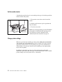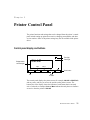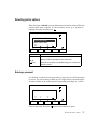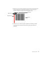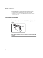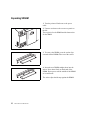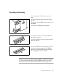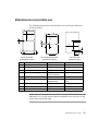
1
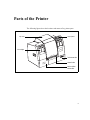
VP2020 Printer
U s e r
G u i d e
Copyright © 2004 VIPColor Technologies Pte Ltd.
This document contains proprietary information that is protected by copyright. All rights are reserved. No part of this document
may be photocopied, reproduced, or translated to another language without the prior written permission of VIPColor
Technologies Pte Ltd.
Warranty
VIPColor Technologies Pte Ltd takes steps to ensure that this user guide is correct; however, errors may occur, and the
information in this guide is subject to change without notice.
VIPColor Technologies Pte Ltd. makes no warranty of any kind with regard to this material, including but not
limited to, the implied warranties of merchantability and fitness for a particular purpose.
VIPColor Technologies, Pte Ltd. shall not be liable for errors contained herein or for incidental or consequential damages in
connection with furnishing, performance, or use of this material.
Trademarks
Microsoft, Windows, Windows NT, Windows 2000, and Windows XP are registered trademarks of Microsoft Corporation in the
U.S.A. and/or other countries.
TrueType fonts are a registered trademark of Apple Computer, Inc.
PCL is a trademark of Hewlett-Packard Company
VIPColor is a trademark of VIPColor Technologies, U.S.A., Inc
All other company and product names may be the registered trademarks or trademarks of their respective owners.
VP2020 User Guide 05/2004
WARNING
Electrical Shock Hazard
Serious shock hazard leading to death or injury may result if you do not take the following precautions:
• Ensure that the AC power outlet (mains) has a protective earth (ground) terminal.
• Disconnect the printer from the power source prior to performing any troubleshooting procedures.
• Prevent water or any other liquids from running onto electrical components or circuits, or through openings in the enclosure.
ii
Contents
Parts of the Printer
v
1 Setting up the Printer
1
Choose a location for the printer . . . . . . . . . . . . . . . . . . . . . . . . . . . . . . . . . . . . 1
Unpack the printer . . . . . . . . . . . . . . . . . . . . . . . . . . . . . . . . . . . . . . . . . . . . . . . 2
Connect the power cable . . . . . . . . . . . . . . . . . . . . . . . . . . . . . . . . . . . . . . . . . . 3
Install printheads and cartridges . . . . . . . . . . . . . . . . . . . . . . . . . . . . . . . . . . . . 4
Install ink cartridges . . . . . . . . . . . . . . . . . . . . . . . . . . . . . . . . . . . . . . . . . . . 4
Install printhead cleaners . . . . . . . . . . . . . . . . . . . . . . . . . . . . . . . . . . . . . . . 5
Install printheads . . . . . . . . . . . . . . . . . . . . . . . . . . . . . . . . . . . . . . . . . . . . . 6
Load continuous media . . . . . . . . . . . . . . . . . . . . . . . . . . . . . . . . . . . . . . . . . . . 8
Run the printhead alignment procedure . . . . . . . . . . . . . . . . . . . . . . . . . . . . . 15
Connect the printer to a computer . . . . . . . . . . . . . . . . . . . . . . . . . . . . . . . . . . 16
Connect the printer to a network . . . . . . . . . . . . . . . . . . . . . . . . . . . . . . . . . . . 17
Enter TCP/IP parameters. . . . . . . . . . . . . . . . . . . . . . . . . . . . . . . . . . . . . . 18
Install the printer driver . . . . . . . . . . . . . . . . . . . . . . . . . . . . . . . . . . . . . . . . . . 20
Set up email warnings (optional) . . . . . . . . . . . . . . . . . . . . . . . . . . . . . . . . . . . 22
2 Printing on Different Types of Media
23
About color profiles . . . . . . . . . . . . . . . . . . . . . . . . . . . . . . . . . . . . . . . . . . . . . 23
Load a new media roll . . . . . . . . . . . . . . . . . . . . . . . . . . . . . . . . . . . . . . . . . . . 24
Set the media selector . . . . . . . . . . . . . . . . . . . . . . . . . . . . . . . . . . . . . . . . 32
Change printer settings . . . . . . . . . . . . . . . . . . . . . . . . . . . . . . . . . . . . . . . 32
Barcode safe mode . . . . . . . . . . . . . . . . . . . . . . . . . . . . . . . . . . . . . . . . . . . . . 33
3 Printer Control Panel
35
Control panel display and buttons . . . . . . . . . . . . . . . . . . . . . . . . . . . . . . . . . . 35
Selecting printer options . . . . . . . . . . . . . . . . . . . . . . . . . . . . . . . . . . . . . . . . . 37
Entering a password . . . . . . . . . . . . . . . . . . . . . . . . . . . . . . . . . . . . . . . . . 37
Main menu . . . . . . . . . . . . . . . . . . . . . . . . . . . . . . . . . . . . . . . . . . . . . . . . . . . . 38
Summary of submenus and options . . . . . . . . . . . . . . . . . . . . . . . . . . . . . 39
Submenus and options . . . . . . . . . . . . . . . . . . . . . . . . . . . . . . . . . . . . . . . . . . 41
PRINTHEAD MAINTENANCE menu . . . . . . . . . . . . . . . . . . . . . . . . . . . . . 41
TEST menu . . . . . . . . . . . . . . . . . . . . . . . . . . . . . . . . . . . . . . . . . . . . . . . . 42
ADVANCED menu . . . . . . . . . . . . . . . . . . . . . . . . . . . . . . . . . . . . . . . . . . . 44
MAINTENANCE menu. . . . . . . . . . . . . . . . . . . . . . . . . . . . . . . . . . . . . . . . 46
iii
OPTIONS menu. . . . . . . . . . . . . . . . . . . . . . . . . . . . . . . . . . . . . . . . . . . . . 47
COUNTRY CONFIG menu . . . . . . . . . . . . . . . . . . . . . . . . . . . . . . . . . . . . 48
INTERFACE menu. . . . . . . . . . . . . . . . . . . . . . . . . . . . . . . . . . . . . . . . . . . 49
PASSWORD menu . . . . . . . . . . . . . . . . . . . . . . . . . . . . . . . . . . . . . . . . . . 50
4 Printer Internal Web Pages
51
Set up a connection. . . . . . . . . . . . . . . . . . . . . . . . . . . . . . . . . . . . . . . . . . . . . 51
Home page . . . . . . . . . . . . . . . . . . . . . . . . . . . . . . . . . . . . . . . . . . . . . . . . 53
Password. . . . . . . . . . . . . . . . . . . . . . . . . . . . . . . . . . . . . . . . . . . . . . . . . . . . . 54
Current Active Stock . . . . . . . . . . . . . . . . . . . . . . . . . . . . . . . . . . . . . . . . . . . . 55
Metrics . . . . . . . . . . . . . . . . . . . . . . . . . . . . . . . . . . . . . . . . . . . . . . . . . . . . . . . 56
Option Install . . . . . . . . . . . . . . . . . . . . . . . . . . . . . . . . . . . . . . . . . . . . . . . . . . 58
Test Functions . . . . . . . . . . . . . . . . . . . . . . . . . . . . . . . . . . . . . . . . . . . . . . . . . 61
Available Fonts . . . . . . . . . . . . . . . . . . . . . . . . . . . . . . . . . . . . . . . . . . . . . . . . 62
Set Up Email Warnings . . . . . . . . . . . . . . . . . . . . . . . . . . . . . . . . . . . . . . . . . . 63
Country Configuration . . . . . . . . . . . . . . . . . . . . . . . . . . . . . . . . . . . . . . . . . . . 65
5 Changing Cartridges and Printheads
67
Replace an ink cartridge . . . . . . . . . . . . . . . . . . . . . . . . . . . . . . . . . . . . . . . . . 68
Replace a printhead . . . . . . . . . . . . . . . . . . . . . . . . . . . . . . . . . . . . . . . . . . . . 69
Replace a printhead cleaner . . . . . . . . . . . . . . . . . . . . . . . . . . . . . . . . . . . . . . 73
6 Troubleshooting
75
Error messages on control panel. . . . . . . . . . . . . . . . . . . . . . . . . . . . . . . . . . . 75
If the carriage is unable to move . . . . . . . . . . . . . . . . . . . . . . . . . . . . . . . . 77
If the media is jammed in the printer . . . . . . . . . . . . . . . . . . . . . . . . . . . . . 77
Print quality problems . . . . . . . . . . . . . . . . . . . . . . . . . . . . . . . . . . . . . . . . . . . 80
Adjustments and calibrations. . . . . . . . . . . . . . . . . . . . . . . . . . . . . . . . . . . . . . 81
Printhead alignment. . . . . . . . . . . . . . . . . . . . . . . . . . . . . . . . . . . . . . . . . . 81
Media calibration . . . . . . . . . . . . . . . . . . . . . . . . . . . . . . . . . . . . . . . . . . . . 85
Printer maintenance . . . . . . . . . . . . . . . . . . . . . . . . . . . . . . . . . . . . . . . . . . . . 88
Clean contacts on the printhead . . . . . . . . . . . . . . . . . . . . . . . . . . . . . . . . 88
7 Optional Accessories
89
Expanding SDRAM . . . . . . . . . . . . . . . . . . . . . . . . . . . . . . . . . . . . . . . . . . . . . 90
Expanding flash memory . . . . . . . . . . . . . . . . . . . . . . . . . . . . . . . . . . . . . . . . . 91
8 Printer Specifications
93
Media dimensions and printable area . . . . . . . . . . . . . . . . . . . . . . . . . . . . . . . 95
iv
Parts of the Printer
The following figures show the locations and names of key printer parts.
top cover
control panel
ink cartridge
front access door
manual cutter
service station
access door
v
USB connector
PCMCIA slot
Ethernet connector
memory
expansion bay
rear access door
Power switch*
power socket
* Always turn the printer off using the Power button on the control panel, to
ensure that the printhead carriage is returned to its proper position at the left side
of the printer.
vi
Chapter 1
Setting up the Printer
To set up the printer, you need to do the following:
• Choose a suitable location for setting up the printer.
• Unpack the printer.
• Connect the power cable.
• Install the ink cartridges, printhead cleaners, and printheads.
• Load continuous media to run the printhead alignment procedure.
• Once complete, replace the continuous media with the media for printing.
• Connect the printer to your computer and/or network.
• Install the printer driver.
Choose a location for the printer
Select a suitable location for the printer, following these guidelines:
• The area must be well ventilated and clean.
• Avoid places where the printer can be exposed to direct sunlight, liquids or
chemicals.
• Avoid places that can be subject to abrupt changes in temperature and
humidity.
• Select a surface that is sturdy enough to take the weight of the printer.
NOTE: It is recommended that the printer be run on an uninterruptable power
supply.
SETTING UP THE PRINTER
1
Unpack the printer
When unpacking the printer, take care as it is heavy. You should always get help
from another person to unpack and lift the printer.
1. Carefully lift the printer out of the box and set it on a level and sturdy surface in
the selected location.
2. Open the top cover of the printer.
3. Push and hold the green lever to lift up the frame that supports the media roll.
4. Carefully remove the packing material inside the printer.
5. Push and hold the green lever to lower the frame, then close the printer cover.
You should see two smaller boxes containing the printheads and ink cartridges
inside the printer box.
Do not throw away the printer box and packing materials in case you need to use
them again.
2
SETTING UP THE PRINTER
Connect the power cable
NOTE: Make sure the packing material inside
the printer has been removed and the printer
cover is closed.
1. Attach the power cable securely to the printer
before plugging the other end into a power outlet.
2. Turn the printer on using the Power switch near
the power connector.
NOTE: Do not turn off the printer using the Power
Power switch
switch at the back of the printer. Always turn it off
using the Power button on the control panel at the
front of the printer. This ensures that the printhead
carriage is returned to its proper position at the left
side of the printer and that the printheads are
protected.
SETTING UP THE PRINTER
3
Install printheads and cartridges
The printer uses four ink cartridges (CMYK – Cyan, Magenta, Yellow and
blacK), five printheads, and five printhead cleaners (there are two black
printheads). The ink cartridges, printheads and printhead cleaners have to be
correctly installed before the printer will function properly.
ink cartridge
printhead
printhead cleaner
Install ink cartridges
Each color cartridge fits in a specific slot, as
indicated by the colored labels over the slots. From
left to right, the colors are magenta, yellow, cyan
and black.
1. Remove a cartridge from its packaging.
2. Push the cartridge firmly into the correct slot.
If you are not able to snap the cartridge in place, it
is probably in the wrong slot.
3. Install the other cartridges in the same way.
4
SETTING UP THE PRINTER
Install printhead cleaners
Each new printhead comes with a printhead cleaner.The printhead cleaners
protect the printheads when the printer is not in use, and keep the printheads
clean for optimum print quality. The printhead cleaners are installed in the
service station at the bottom left of the printer, below the printhead carriage.
Each printhead cleaner is designed to work with a particular color printhead. The
printhead cleaners must therefore be installed in the same order as the
printheads, as indicated by the colored labels on the service station. From left to
right, the colors are magenta, yellow, cyan, black and black.
1. Slide the lock to the right to release the service
station access door.
2. Remove the printhead cleaner from the
packaging.
3. Insert the printhead cleaner into the correct slot
in the service station and push it in firmly by its
top. You should hear a click as it snaps into place.
4. Install the other printhead cleaners in the same
way.
NOTE: When all the printhead cleaners are
installed, they do not line up.
5. Close the access door and slide the lock back to
the left to lock it.
SETTING UP THE PRINTER
5
Install printheads
1. Open the top cover of the printer.
The printhead carriage will move to the center of
the printer.
2. Remove the packing tape from each of the
latches on the carriage.
3. Remove a printhead from its packaging, then
remove the protective cap and tape.
NOTE: Take care not to touch the nozzles of the
printhead.
Keep the protective cap and tape so that you can
replace them on the printhead, if you should ever
need to remove it from the printer.
6
SETTING UP THE PRINTER
4. Look at the carriage, which has colored labels
showing where the printhead for each color should
be installed. Release and flip up the latch for the
printhead you are installing.
5. Push the printhead firmly into the carriage.
NOTE: You will not be able to push the printhead
in place if it is in the wrong slot.
6. Flip the latch down over the printhead and
secure it by pressing down.
7. Repeat steps 3 to 6 until all the printheads have
been installed.
8. Close the top cover.
The printer will check and initialize the printheads.
SETTING UP THE PRINTER
7
Load continuous media
The following cutaway view shows the path of the media through the printer and
important parts inside the printer.
media roll loaded
in spindle
clamp that locks
spindle in place
(one on each
side of the roll)
lever to release
frame
frame that supports
media roll
pinch rollers
manual cutter
media sensor
Media path through the printer
The first time you set up the printer, load the continuous media provided with
the printer. This media is needed to run the printhead alignment procedure.
1. Open the printer’s top cover.
8
SETTING UP THE PRINTER
2. Push and hold the green lever to lift up the
frame that supports the media roll. Make sure you
push the frame up to its highest level so that the
pinch rollers (see the figure on page 8) are raised
above the platen.
3. Push back the clamps (which are marked with
green labels) at both sides of the frame.
clamp
4. Remove the spindle from the frame, by lifting it
slightly upwards and towards yourself.
SETTING UP THE PRINTER
9
5. Pull the green lock ring and the right side of the
spindle off the central core.
6. Insert the spindle into the roll. The free end of
the roll should hang off the front.
7. Replace the right side of the spindle and push it
against the roll. If you can’t fit it back over the
central core, rotate it slightly so that the notches on
the two parts line up properly. Then replace the
lock ring.
10
SETTING UP THE PRINTER
8. Place the spindle into the frame. The gear of the
spindle should be on the left and the free end of the
roll in front.
9. Slip the media loading tool over the free end of
the roll. Align the media against the left side of the
tool.
10. Reach inside the printer and push the green
media width guide to the right.
SETTING UP THE PRINTER
11
11. Feed the loading tool through the opening
above the rollers at the back of the printer.
12. Continue feeding the media in until it appears
under the pinch rollers. Make sure the media runs
under the Top-of-Form sensor (on the left, in front
of the pinch rollers).
13. Finally, feed the media through the cutter.
12
SETTING UP THE PRINTER
14. Remove the media loading tool.
15. Make sure the edge of the media is lined up
against the red alignment mark on the left.
Check that the media has been fed correctly through the printer (steps 11 to 15) as shown below.
under the
Top-of-Form sensor
against the red
alignment mark
under the pinch rollers
through the manual cutter
SETTING UP THE PRINTER
13
16. Move the media width guide against the right
edge of the media.
alignment
arrow
ruler
Placement of media width guide
• Pre-cut labels
4.0
green band
on ruler
alignment
arrow
• Continuous or tag media
4.0
green lever
To position the media width guide correctly, you
can make use of the alignment arrow and the green
bands on the ruler.
The diagram on the left illustrates the correct
placement for 4” media:
• For pre-cut labels, the alignment arrow should be
against the right side of the green band at the 4”
mark.
• For continuous media or tag media, the arrow
should be against the left side of the green band at
the 4” mark.
17. Push and hold the green lever to lower the
frame. Be careful when lowering the frame. The
clamps on both sides of the frame will close
automatically.
18. Close the printer cover.
14
SETTING UP THE PRINTER
ONLINE
Feed
Menu
19. Press the Feed button on the control panel. The
printer will feed the media and correctly position it
for printing.
The control panel will show that the printer is now
ONLINE .
Run the printhead alignment procedure
The automatic printhead alignment procedure must be performed during
installation and whenever you load new printheads in the printer. This will
ensure that all the printheads line up and maximize print quality. If you do not do
this, your printout can look fuzzy or blurred.
PRINTHEAD MAINTENANCE
CLEAN PRINTHEADS
PRINT STATUS LABEL
esc
INSTALL/REPLACE
PRINTHEAD ALIGNMENT
CHECK
esc
1. On the control panel,
– Press the Menu button to enter the main menu.
– Select PRINTHEAD MAINTENANCE .
– Select PRINTHEAD ALIGNMENT.
(Press or to move through the options; press
to select an option.)
The alignment procedure will take between 10 and
30 minutes to complete. A message appears on the
control panel when it is completed.
Once the printhead alignment procedure is completed, remove the 6” continuous
media roll and load the media you will be working with.
See Load a new media roll on page 24 which describes the additional steps
required when loading new media for printing.
SETTING UP THE PRINTER
15
Connect the printer to a computer
To connect the printer to a single computer, use the USB connector at the back
of the printer.
NOTE: If the computer does not have a USB connector or the operating system
does not support USB, connect the printer using a CAT5 cross-over cable as
described in the next section.
1. Insert the USB cable into the USB connector at the back of the printer.
2. Connect the other end of the USB cable to your computer. When you do so, the
computer will display a message that new hardware has been found. Install the
printer driver from CD-ROM provided with the printer (see page 20).
NOTE: It can take up to five minutes for the computer to recognize the printer.
Please do not proceed with printer installation until the computer has discovered
the printer.
16
SETTING UP THE PRINTER
Connect the printer to a network
To connect the printer to a network, use the 10BaseT Ethernet connector at the
back of the printer. If connecting the printer directly to a single computer, use a
CAT5 cross-over cable.
1. Insert the cable into the Ethernet connector at the back of the printer.
2. Connect the other end of the cable to the Ethernet port on your network hub or
computer.
3. Set up the TCP/IP parameters for the printer. Contact your network
administrator for the required parameters.
Detailed instructions for entering the parameters are given on the following
pages. The procedure depends on whether you are connecting the printer to:
• A single computer. You will have to enter the IP address and subnet mask.
• A network that uses DHCP or BOOTP to automatically allocate an IP
address to the printer.
• A network that requires a fixed IP address for the printer. You will have to
enter the IP address together with the subnet mask, gateway, and DNS.
4. IMPORTANT: When you complete the network settings, reset the printer by
turning it off and on again. Always use the Power button on the control panel to
turn the printer on or off.
SETTING UP THE PRINTER
17
Enter TCP/IP parameters
The TCP/IP parameters are entered using the printer’s control panel. On the
control panel, press or to scroll through the menus; and press
to select
an option.
Connecting to a single computer
1. When giving the printer an IP address, you may have to look at or change the IP
setting of your computer, because the first three sets of digits in the IP address of
the computer and printer must be the same. For example, the computer’s IP
address could be 192.168.188.10 while the printer’s IP address is
192.168.188.20.
2. Set up a fixed IP address:
a. On the control panel, press the Menu button to enter the main menu.
b. Select INTERFACE .
c. Select TCPIP.
d. Select MANUAL .
e. Select IP ADDR .
The default IP address will be displayed with the cursor under the first digit.
• Press to scroll to the desired value and press
to select it.
The cursor will move to the next digit.
• Repeat this step to complete the IP address.
• When done, press
again and then press esc .
3. Follow the instructions in step 2, but instead of IP ADDR , select SUBNET MASK .
Set the subnet mask (e.g. 255.255.255.0) but leave the gateway and DNS alone.
Connecting to a network that uses DHCP or BOOTP
1. Specify DHCP or BOOTP:
a. On the control panel, press the Menu button to enter the main menu.
b. Select INTERFACE .
c. Select TCPIP.
d. Select DHCP or BOOTP.
18
SETTING UP THE PRINTER
Connecting to a network that requires a fixed IP address
1. Set up a fixed IP address (network):
a. On the control panel, press the Menu button to enter the main menu.
b. Select INTERFACE .
c. Select TCPIP.
d. Select MANUAL .
e. Select IP ADDR .
The default IP address will be displayed with the cursor under the first digit.
• Press to scroll to the desired value and press
to select it.
The cursor will move to the next digit.
• Repeat this step to complete the IP address.
• When done, press
again and then press esc .
2. Follow the instructions in step 1, but instead of IP ADDR , select SUBNET MASK ,
GATEWAY, and DNS in turn and set the values in the same way.
SETTING UP THE PRINTER
19
Install the printer driver
The printer driver works with Windows 98 and above (for detailed requirements,
see page 94). Install the printer driver from the CD-ROM labeled ‘BarTender
Label Printing Software, VIPColor Special Edition’.
1. Insert the CD-ROM into the drive.
2. From the setup screen, select Seagull Printer Drivers .
3. From the next screen, select Install Printer Driver.
4. Follow the instructions on the screen to complete the installation. The actual
procedure will depend on your operating system.
20
SETTING UP THE PRINTER
You can also install the BarTender Label Printing Software which lets you
design and print labels using various types of image files (including .bmp, .dxf,
.img, .jpg, .pcx, .dcx, .png, and .tif). You may also use other Windows
applications to design labels and use other types of image files.
NOTE: VIPColor Technologies endeavours to test the driver with multiple
software applications, but does not guarantee its error-free operation, and
disclaims any liability resulting therefrom.
Additional information on installing the printer driver can be found on the
CD-ROM or downloaded from the VIPColor website.
SETTING UP THE PRINTER
21
Set up email warnings (optional)
If you are using an Ethernet connection, the printer can be set up to send out
email messages to selected recipients when problems are encountered, so that
action can be taken.
• An email account must be set up for the printer. You will need to know the
account name and password, as well as the POP3 and SMTP server address.
• Email warnings must be enabled from the printer’s control panel (see step 1
below).
• The printer’s email settings and the recipients are set up from the printer’s
internal web pages (see chapter 4).
1. Enable email warnings from the printer’s control panel:
– Press the Menu button to enter the main menu.
– Select INTERFACE .
– Select EMAIL .
– Press
(Enter) to enable email warnings.
(Press
or
to move through the options; press
to select an option.)
2. Log on to the printer’s internal web pages as follows: Enter the printer’s IP
address in your web browser, then enter the user name and password (see
page 51) in the dialog box that appears.
3. From the printer’s home page, select Setup email warnings.
4. Click on the ‘Set up email properties’ link.
5. Enter the printer’s email account settings and click Apply.
6. Enter the email addresses of the people who will be sent the warning messages.
You can specify up to three recipients.
7. Click Apply to save the settings.
22
SETTING UP THE PRINTER
Chapter 2
Printing on Different Types of Media
The printer supports a variety of label types and shapes, from die-cut labels to
continuous media. For best operation, it is strongly recommended that you use
the specially coated media types listed below.
About color profiles
Differences in the composition and thickness of different types of media require
the printer to handle each type differently. For each media type that the printer
supports, a color profile has been created. This color profile not only defines
how color should be printed, but also various other settings that optimize the
output quality for the media type.
It is therefore important, whenever you load a new type of media in the printer,
that you select the same type in the printer driver. This ensures that the
appropriate color profile is used for printing. If you do not select the correct
media type, the output quality may not be optimal.
New profiles can be downloaded and selected using the printer driver. You can
download up to seven other profiles into the printer at any one time. All internal
pre-programmed profiles support all print modes, while new profiles are made
specifically for the print mode that they will be used with (Fast, Normal, High or
Premium). Depending on the print mode you select in the printer driver, the
printer will either optimize quality or speed.
Color profiles are currently available for the following media types:
• STANDARD MATT LABEL 1
• STANDARD MATT TAG
• STANDARD SEMI GLOSS LABEL
• STANDARD MATT LABEL 1
• STANDARD SYNTHETIC LABEL
• STANDARD GLOSS
PRINTING ON DIFFERENT TYPES OF MEDIA
23
Your label supplier can tell you which profile is best for your media.
Load a new media roll
The following cutaway view shows the path of the media through the printer and
important parts inside the printer.
media roll loaded
in spindle
clamp that locks
spindle in place
(one on each
side of the roll)
lever to release
frame
frame that supports
media roll
pinch rollers
manual cutter
media sensor
Media path through the printer
After loading a new roll of media, always check to see if you need to:
• Set the media selector (page 32)
• Change printer settings (page 32)
24
PRINTING ON DIFFERENT TYPES OF MEDIA
1. Open the printer’s top cover.
2. Push and hold the green lever to lift up the
frame that supports the media roll. Make sure you
push the frame up to its highest level so that the
pinch rollers (see the figure on page 24) are raised
above the platen.
3. Push back the clamps (which are marked with
green labels) at both sides of the frame.
clamp
PRINTING ON DIFFERENT TYPES OF MEDIA
25
4. Remove the spindle from the frame, by lifting it
slightly upwards and towards yourself.
If you are replacing the media roll, gently pull the
free end of the roll out of the printer.
5. Pull the green lock ring and the right side of the
spindle off the central core.
Slip the old media roll off the central core.
6. Insert the spindle into the new roll. The free end
of the roll should hang off the front.
26
PRINTING ON DIFFERENT TYPES OF MEDIA
7. Replace the right side of the spindle and push it
against the roll. If you can’t fit it back over the
central core, rotate it slightly so that the notches on
the two parts line up properly. Then replace the
lock ring.
8. Place the spindle into the frame. The gear of the
spindle should be on the left and the free end of the
roll in front.
9. Slip the media loading tool over the free end of
the roll. Align the media against the left side of the
tool.
PRINTING ON DIFFERENT TYPES OF MEDIA
27
10. Reach inside the printer and push the green
media width guide to the right.
11. Feed the loading tool through the opening
above the rollers at the back of the printer.
12. Continue feeding the media in until it appears
under the pinch rollers. Make sure the media runs
under the Top-of-Form sensor (on the left, in front
of the pinch rollers).
28
PRINTING ON DIFFERENT TYPES OF MEDIA
13. Finally, feed the media through the cutter.
14. Remove the media loading tool.
15. Make sure the edge of the media is lined up
against the red alignment mark on the left.
PRINTING ON DIFFERENT TYPES OF MEDIA
29
Check that the media has been fed correctly through the printer (steps 11 to 15) as shown below.
under the
Top-of-Form sensor
against the red
alignment mark
under the pinch rollers
through the manual cutter
alignment
arrow
ruler
30
PRINTING ON DIFFERENT TYPES OF MEDIA
16. Move the media width guide against the right
edge of the media.
Placement of media width guide
green band
on ruler
• Pre-cut labels
alignment
arrow
4.0
• Continuous or tag media
4.0
green lever
To position the media width guide correctly, you
can make use of the alignment arrow and the green
bands on the ruler.
The diagram on the left illustrates the correct
placement for 4” media:
• For pre-cut labels, the alignment arrow should be
against the right side of the green band at the 4”
mark.
• For continuous media or tag media, the arrow
should be against the left side of the green band at
the 4” mark.
17. Push and hold the green lever to lower the
frame. Be careful when lowering the frame. The
clamps on both sides of the frame will close
automatically.
18. Close the printer cover.
ONLINE
Feed
Menu
19. Press the Feed button on the control panel. The
printer will feed the media and correctly position it
for printing.
The control panel will show that the printer is now
ONLINE .
Now check the media selector and printer settings
as described in the following sections.
PRINTING ON DIFFERENT TYPES OF MEDIA
31
Set the media selector
Check that the media selector is set according to the type of media (tag media or
labels) loaded in the printer.
1. Flip open the access door at the front of the
printer.
2. Push the media selector up for tag media and
down for labels.
3. Close the access door.
NOTE: If you change media types and find that the
media selector
print quality is diminished when printing on the
new media type, run the automatic media
calibration procedure described on page 85.
Change printer settings
Whenever you load a new media type in the printer, make sure you select the
same media type in the printer driver before printing. This ensures that the
appropriate color profile is used for printing (see page 23 for information on
color profiles). If you do not select the correct media type, the output quality
may be not be optimal.
In addition to the media type, there are other settings such as the media
dimensions, print mode, and sensor type. For more information on the available
printer settings, refer to the printer driver’s online help.
32
PRINTING ON DIFFERENT TYPES OF MEDIA
Barcode safe mode
The VP2020 has a special Barcode safe mode which ensures that the printing of
barcodes is optimized for the best readability. In this mode, the printer adjusts
the way that it prints to produce better optimized barcodes. You may notice a
reduction in the print speed when printing barcodes.
To turn Barcode safe mode on, do the following:
1. On the printer’s control panel,
– Press the Menu button to enter the main menu.
– Select ADVANCED .
– Select BARCODE SAFE MODE .
(Press
or
to move through the options; press
to select an option.)
PRINTING ON DIFFERENT TYPES OF MEDIA
33
34
PRINTING ON DIFFERENT TYPES OF MEDIA
Chapter 3
Printer Control Panel
The printer functions and settings that can be changed from the printer’s control
panel include setting up optional accessories, changing consumables, and other
service routines. Some of the printer settings may also be available in the printer
driver.
Control panel display and buttons
Error light
Power light
ONLINE
Displays status
and messages
Feed
Menu
Power button
Esc
Enter
or Pause
The control panel displays the printer status (for example, ONLINE or PRINTING )
and any errors, and lets you access the options on the printer’s menu. The
bottom line of the display shows the function of each button that is currently
active. In the above example, Feed and Menu indicate that only these two buttons
are active when the printer is ONLINE .
PRINTER CONTROL PANEL
35
Button/Light
36
Description
Error light
Turns on when errors occur.
Power light
Turns on when the power is turned on.
Flashes when data is being received.
Esc
The leftmost button is the Esc button which is used to cancel the current
function, for example, to cancel the current print job. When a function can
be canceled, ‘Esc’ appears over the button.
Feed
Feeds a single label.
Menu
Enters the menu of printer options.
Enter
Selects an option on the menu or confirms an action. When this button is
active,
appears over the button.
Pause/Resume
Allows you to pause or resume printing. When this button is active, Pause
or Resume shows over the button, to indicate the options.
Power button
Turns the printer on or off. Always turn off the printer using this Power
button (rather than the Power switch at the back of the printer), as it
ensures that the printheads are returned to their storage position at the
side of the printer.
PRINTER CONTROL PANEL
Selecting printer options
When the printer is ONLINE , press the Menu button to take the printer offline and
enter the main menu of options. To select an option, use the or button to
highlight the option and then press .
PRINTHEAD MAINTENANCE
CLEAN PRINTHEADS
PRINT STATUS LABEL
esc
Press this
To do this
Esc
Return to the previous menu.
Move up or down through options in the current menu.
(Enter)
Select the current option, which will either bring you to a submenu or
perform a function.
Entering a password
If a submenu or option has been protected by a password, you will be prompted
to enter it. The password may contain up to five digits and are entered using the
first three buttons on the control panel (corresponding to the digits 0, 1, and 2).
Enter Password
0
1
2
Enter the password, then press
to access the submenu or option.
PRINTER CONTROL PANEL
37
Main menu
The printer options are organized in a hierarchy of menus. The options on the
main menu are as follows:
Option
38
Description
PRINTHEAD
MAINTENANCE
Menu of options that let you replace and check the printheads.
CLEAN PRINTHEADS
Starts a cleaning cycle of the printheads.
PRINT STATUS LABEL
Prints a status label which is useful for troubleshooting.
TEST
Menu of test labels that you can print. This menu is not password
protected.
ADVANCED
Menu of service facilities. This menu can be protected by a level 2
password (see page 50).
MAINTENANCE
Menu of maintenance options. For example, updating the
firmware. This menu is not password protected.
OPTIONS
Menu for setting up optional accessories such as the automatic
cutter. This menu can be protected by a level 1 password (see
page 50).
COUNTRY CONFIG
Menu for selecting the display language and units of measure.
This menu is not password protected.
INTERFACE
Menu for setting up the printer interface. This menu can be
protected by a level 1 password (see page 50).
PASSWORD
Lets you change the level 1 and 2 passwords (see page 50) for the
control panel. This menu can be protected by a level 2 password.
PRINTER CONTROL PANEL
Selecting any of the options on the main menu displays a submenu (except for
the CLEAN PRINTHEADS and PRINT STATUS LABEL options). The submenus and
options are described in the following pages.
Summary of submenus and options
The following charts show the hierarchy of menus and submenus.
PRINTER CONTROL PANEL
39
* For information about passwords, see page 50.
40
PRINTER CONTROL PANEL
Submenus and options
PRINTHEAD MAINTENANCE menu
This shows a menu of options that let you replace and check the printheads.
Option
Description
INSTALL/REPLACE
Displays instructions for changing
printheads.
PRINTHEAD
ALIGNMENT
Runs the automatic alignment
procedure for new printheads. Load a
roll of 6” continuous media before
running this procedure.
CHECK
Checks the printheads.
LIGHT CLEAN
Starts a light cleaning of the
printheads.
HEAVY CLEAN
Starts a thorough cleaning of the
printheads.
MANUAL STOCK
CALIBRATION
[Select the media type]
Lets you make fine adjustments to
the line feed accuracy to compensate
for differences in media thickness.
If the printout shows gaps at regular
intervals, press
to increase the
current value. If the printout shows
overlaps at regular intervals, press
to decrease the value.
PRINTER CONTROL PANEL
41
TEST menu
This shows a menu of test labels that you can print.
Option
Description
TEST PRINTS
TEST PRINT A
TEST PRINT B
Select an option to print the
predefined test labels. Load a roll of
6” continuous media before running
this procedure.
FONT EXAMPLE
ARIAL
ARIAL BOLD
ARIAL BOLD ITALIC
...
Displays a list of fonts that have been
downloaded and are available in the
printer. Select a font to print a
sample.
PAPER STATUS
Displays paper width, height, and gap
as well as number of labels in the last
job sent to the printer.
NOTE: You may need to press esc on the control panel to stop a test.
42
PRINTER CONTROL PANEL
The following is a sample status label:
VIPColor VP2020 Diagnostic Page
Model ID: VIPColor VP2020 Label Printer
Main board firmware version: 3.0
built at April 02, 2004 11:38:41 -ROP
Mech board firmware version: 07000396
Carriage board firmware version: 0010004A
Printer serial number: SG2022302H
Installed SDRAM size (byte): 67108864
Total # inches printed: 39684
Total # labels printed: 6614
IO information
TCP/IP STATUS: READY
Mac address (wired): 00:50:F7:10:01:2E
IP address (wired): 192.168.188.182
Primary DNS address (wired): 255.255.255.255
Gateway address (wired): 192.168.188.254
Subnet mask (wired): 255.255.255.0
No wireless Ethernet card installed
"Type1
"Type2
"Type3
"Type4
cartridges
cartridges
cartridges
cartridges
used:
used:
used:
used:
107"
0"
0"
0"
PRINTER CONTROL PANEL
43
ADVANCED menu
This shows a menu of service options.
Option
FACTORY DEFAULT
READ METRICS
44
Description
Changes all settings back to the
factory defaults and clears the
printer’s Flash and DRAM
memory areas.
[COLOR] PRINTHEAD
[COLOR] CARTRIDGE
[COLOR] PH CLEANER
CARRIAGE
PRINTER
TOTAL CARTRIDGES
TOTAL PRINTHEADS
Displays list of items for which
usage data is available. Select an
item to show one or more of the
following:
Status
Usage Time
Ink Consumed
Last Job
Number of cycles
Total printed length
BARCODE SAFE
MODE
When this option is enabled, the
printer checks the black
printheads prior to printing
barcodes.
FANFOLD SUPPORT
Select this option when you use
fanfold media.
SEEK LABEL HEIGHT
Utilizes sensor to seek physical
height of label prior to printing.
This option will position print with
higher accuracy, but will slow
down printing considerably.
PRINTER CONTROL PANEL
Option
Description
FIRST LABEL MODE
Stops the label from going to the
cutter position after a print job,
thereby preventing unwanted
paper movement back and forth
in between print jobs.
When this option is off, the printer
will position the paper for cutting if
the next print job does not arrive
within a predefined period.
LABEL COUNTER
When printing, displays the
number of the current page on the
control panel.
PRINTER CONTROL PANEL
45
MAINTENANCE menu
This shows a menu of maintenance options.
Option
Option
CHANGE SERVICE
STATION
PRINTHEAD
ALIGNMENT
Lets you change the printhead
cleaners.
AUTO ALIGNMENT
MANUAL ALIGNMENT
STOCK CALIBRATION
Description
Runs the automatic alignment
procedure for new printheads. Load a
roll of 6” continuous media before
starting this procedure.
PRINT PATTERN 1
PRINT PATTERN 2
PLOT 1
PLOT 2
...
Runs the manual alignment
procedure for printheads. Follow the
instructions on page 82.
AUTO STOCK
CALIBRATION
Runs the automatic media calibration
procedure (page 85).
MANUAL STOCK
CALIBRATION
Lets you make fine adjustments to the
line feed accuracy to compensate for
changes in media thickness.
If the printout shows gaps at regular
intervals, press
to increase the
current value. If the printout shows
overlaps at regular intervals, press
to decrease the value.
SETUP LABEL
THRESHOLD
Lets you set up special label types
manually. Follow the instructions that
appear on the control panel.
FIRMWARE VERSION
Shows the firmware version.
DISPLAY ERROR
Prints a list of errors. You may be
asked to print this list when you call
for service.
46
PRINTER CONTROL PANEL
OPTIONS menu
This shows the settings for optional accessories such as the automatic cutter.
Option
Description
AUTO CUTTER
Specifies if the automatic cutter is
installed.
SINGLE DISPENSE
Specifies if single dispense mode is
installed.
MANUAL CUTTER
Specifies if the manual cutter is
installed.
GPIO SETUP
Starts or stops the operation of the
GPIO (General Purpose Input/
Output) board.
PRINTER CONTROL PANEL
47
COUNTRY CONFIG menu
This menu lets you select the display language and unit of measure.
Option
LANGUAGE
SELECTED
ENGLISH*
JAPANESE
Lets you select the language
display for the control panel.
UNITS OF MEASURE
INCHES*
MM
Lets you select the unit of measure
used by the printer.
* indicates the default setting
48
Description
PRINTER CONTROL PANEL
INTERFACE menu
This menu shows the printer interface settings.
Option
ETHERNET
DEFAULT TO CABLE
TCPIP
MANUAL
Option
Description
Specifies whether to use the cable or
wireless network connection.
DNS
IP ADDR
SUBNET MASK
GATEWAY
Select MANUAL to enter settings
manually, or select DHCP or BOOTP.
DHCP
BOOTP
EMAIL
Specifies whether the printer should
send warning messages via email on
encountering errors. Enter the email
settings from the printer’s internal
web pages.
Setting the IP address
If you choose to enter the IP address and other settings manually:
• Press the button to scroll through the characters (0 to 9 and period).
• Press the
button to select a character.
• Press the next button to set the next character.
• When you have finished, press the
button again.
Enter New Value
192.168.188.182_
esc
next
PRINTER CONTROL PANEL
49
PASSWORD menu
This menu lets you change the level 1 and 2 passwords for the control panel.
Description
LEVEL 1 PASSWORD
Lets you set the level 1 password.
LEVEL 2 PASSWORD
Lets you set the level 2 password.
The two levels of passwords control access to different types of options. A
level 1 password protects options that operators may need to access, while a
level 2 password protects options not normally used in daily operations. See
Main menu on page 38 which indicates the level of protection for the various
options. The Password menu itself can be protected by a level 2 password.
When the printer is first set up, no passwords are set. It is recommended that you
set them. Keep a copy of the passwords in a safe place.
Setting the passwords
1. From the PASSWORD menu, select the password to change.
2. Enter the new password using the first three buttons on the control panel
(corresponding to the digits 0, 1, and 2). The password can contain a maximum
of five digits, for example, ‘20121’.
Enter New Password
(max 5 chars)
_
0
3. Press the
50
PRINTER CONTROL PANEL
1
button.
2
Chapter 4
Printer Internal Web Pages
If your printer is on a network, you will be able to check its status and settings
from a remote computer. This information is provided in the printer’s internal
web pages, which you can log on to using a standard web browser.
You can also set up the printer to send out email messages when problems occur,
prompting the recipients to take action. Examples of such situations are when
errors are encountered during printing, an ink cartridge needs to be changed, or a
new media roll has to be loaded.
Set up a connection
To access the printer’s internal home page, enter its IP address in your web
browser, then enter the user name and password (see below) in the dialog box
that appears. If a domain name was set up for the printer, you can enter the
printer’s name instead of the IP address.
NOTE: When the printer is first set up, an administrator should log on and
create a new user name for general use.
Logging on for the first time
The printer is set up with the user name ‘administrator’ and the default password
is ‘vipcolor’. An administrator should log on and change the password, then
create a new user name for general use. It is recommended that you restrict the
use of the user name ‘administrator’, which has access to all functions.
PRINTER INTERNAL WEB PAGES
51
To log on and create a user:
1. Enter the printer’s IP address in your web browser.
2. In the dialog box that appears, enter ‘administrator’ for the User Name and
‘vipcolor’ for the Password.
The Password Setup page will appear.
3. Enter a new administrator’s password in the VIP Web Password field and click
Apply.
The home page will appear.
4. Select Password in the left navigation bar.
5. Create a new User Name and corresponding User Password for general use.
6. When you are done, click Apply.
52
PRINTER INTERNAL WEB PAGES
Home page
Once your user name and password are accepted, the printer’s home page shows
the current printer status, and provides links to other web pages in the left
navigation bar.
Option
Description
Password
Displayed only if you log on as ‘administrator’. It allows you to
change the web passwords, the level 1 and 2 passwords for
accessing the printer’s control panel, and the printer name.
Current Active Stock
Shows the parameters for the media currently in the printer.
Metrics
Shows the usage data for the ink cartridges, printheads, printhead
cleaners, and mechanism.
Option Install
Shows which optional accessories have been installed, and the
available memory. It also lets you check the wireless Ethernet and
SIMM settings.
Test Functions
Allows you to test certain printer functions.
Available Fonts
Shows the fonts that are currently available.
PRINTER INTERNAL WEB PAGES
53
Option
Description
Set Up Email Warnings
Allows you to specify who to send email messages to when
problems occur.
Country Configuration
Allows you to select the language and unit of measure.
Home
Returns to the printer’s start page.
VIPColor Website
Links to the VIPColor Website.
Contact Technical
Support
If available, this launches your email program for you to compose a
message to your distributor’s technical support personnel.
Password
This option allows an administrator to change the passwords for accessing the
printer control panel and web pages. You can also change the printer name.
54
PRINTER INTERNAL WEB PAGES
When making changes to the passwords, follow these rules:
Level 1 and Level 2 Password
Maximum of 5 digits (using ‘1’, ‘2’, and ‘3’ only).
VIP Web* and User Password
Maximum of 8 alphanumeric characters.
Printer name
Maximum of 15 alphanumeric characters.
* The VIP Web Password is used to access the printer’s internal web pages.
Current Active Stock
This option lets you verify the settings for the media in the printer before starting
a print run. It shows the settings that have been selected, as well as the actual
dimensions as measured by the printer.
PRINTER INTERNAL WEB PAGES
55
Metrics
This option shows the usage data for the ink cartridges, printheads, printhead
cleaners, and mechanism. To view the data,
1. Select Metrics from the left navigation bar, then select an item.
2. Select the color, if applicable.
For example, select Ink Cartridges, then select Cyan to see the metrics for the
cyan ink cartridge, as shown in the following screen.
56
PRINTER INTERNAL WEB PAGES
PRINTER INTERNAL WEB PAGES
57
Option Install
This option shows which of the optional accessories have been installed in the
printer, and the amount of available memory.
From this page, you can edit the wireless Ethernet settings and check the SIMM
jumper settings.
58
PRINTER INTERNAL WEB PAGES
Specify wireless Ethernet settings
When you install a wireless Ethernet card, be sure to enter the correct settings
for the card. On the Option Install page, click the ‘Not installed’ hyperlink in the
Wireless Ethernet field. This displays the following page:
Enter the settings and click Apply to save. Refer to the user documentation
provided with the wireless Ethernet card for information on the settings.
PRINTER INTERNAL WEB PAGES
59
Check SIMM jumper settings
On the Option Install page, click the hyperlink in the SIMM Size field to check
the jumper settings.
60
PRINTER INTERNAL WEB PAGES
Test Functions
This option allows you to print test labels and to test a number of printer
functions.
Test
Description
Feed
Feeds media through the printer.
Barcode label
Graphic label
Print test labels. Load 6” media before running these
tests.
Check print head
Check the printhead nozzles and display the test results.
Carriage test
Test the carriage.
Service station test
Test the service stations.
Click on a test to run it. A status page will be displayed to inform you when the
test is completed, and report any errors.
PRINTER INTERNAL WEB PAGES
61
Available Fonts
This option shows the fonts that are currently loaded into the memory.
62
PRINTER INTERNAL WEB PAGES
Set Up Email Warnings
This option allows you to set up the printer to send email messages to selected
recipients when any problems occur.
You can specify up to three recipients. You can also add more details to the
standard message sent by the printer. To do so, enter the text in the Warning Add
On field.
To enter or change the printer’s email settings (its email account, password,
POP3 server and SMTP server), click the ‘Set up email properties’ link.
PRINTER INTERNAL WEB PAGES
63
Set up email properties
Fill in the fields and click Apply to save the settings.
64
PRINTER INTERNAL WEB PAGES
Country Configuration
This option lets you select the language and the unit of measure.
Select from the drop-down lists and click Apply to save.
PRINTER INTERNAL WEB PAGES
65
66
PRINTER INTERNAL WEB PAGES
Chapter 5
Changing Cartridges and
Printheads
The printer displays messages to warn you before an ink cartridge, printhead, or
printhead cleaner needs to be replaced. While the printer will still be able to
print, it is best to get replacements ready when you see these messages.
NOTE: Handle all these consumables with care as ink spills may cause damage
to the electronics of the printer and may stain.
CHANGING CARTRIDGES AND PRINTHEADS
67
Replace an ink cartridge
Remove an ink cartridge
1. Push the ink cartridge in and slightly upwards.
It will pop free, allowing you to remove it from the
slot.
Install an ink cartridge
1. Remove the ink cartridge from its packaging.
2. Push the ink cartridge firmly into the slot.
Make sure you are installing the correct color
cartridge. From left to right, the colors are
magenta, yellow, cyan and black. If you are unable
to push the cartridge fully into the slot, it is
probably the wrong color for the slot.
68
CHANGING CARTRIDGES AND PRINTHEADS
Replace a printhead
Each new printhead comes with a printhead cleaner.
NOTE: Always replace the printhead cleaner together with the printhead. If
the printhead cleaner is not replaced, it can affect the print quality and reduce the
life of the printhead.
Remove a printhead
PRINTHEAD MAINTENANCE
CLEAN PRINTHEADS
PRINT STATUS LABEL
esc
INSTALL/REPLACE
PRINTHEAD ALIGNMENT
CHECK
esc
1. On the control panel,
– Press the Menu button to enter the main menu.
– Select PRINTHEAD MAINTENANCE .
– Select INSTALL/REPLACE .
– Select DISPLAY DATA OR CHANGE .
(Press or to move through the options; press
to select an option.)
DISPLAY DATA OR CHANGE
esc
2. Open the top cover of the printer.
CHANGING CARTRIDGES AND PRINTHEADS
69
The printhead carriage will move to the center of
the printer.
green lever
3. For easier access, you may like to lift up the
frame that supports the media roll. Push and hold
the green lever on the frame to lift it.
4. Release and flip up the latch for the printhead to
be replaced.
70
CHANGING CARTRIDGES AND PRINTHEADS
5. Lift the printhead out of the carriage by pulling
the handle on its top.
Install a new printhead
1. Remove the new printhead from its packaging,
then remove the protective tape and cap.
NOTE: Take care not to touch the nozzles of the
printhead.
Keep the protective cap and tape so that you can
replace them on the printhead, if you should ever
need to remove it from the printer.
2. Push the printhead firmly into the carriage.
NOTE: Do not try to install a printhead for one
color into the slot for another color. From left to
right, the colors are magenta, yellow, cyan, black
and black. You can check the colored labels on the
carriage.
CHANGING CARTRIDGES AND PRINTHEADS
71
3. Flip the latch down over the printhead and
secure it by pressing down.
4. Close the printer’s top cover. This returns the
carriage to the left side of the printer.
5. Every time you replace a printhead, always do
the following as well:
– Replace the printhead cleaner (described on
the next page).
– Run the printhead alignment procedure
(described on page 81).
72
CHANGING CARTRIDGES AND PRINTHEADS
Replace a printhead cleaner
Remove a printhead cleaner
1. Slide the lock to the right to release the access
door. The service station will move forward
automatically.
2. Push and hold the tab up to release the
printhead cleaner and pull it out of the slot.
CHANGING CARTRIDGES AND PRINTHEADS
73
Install a printhead cleaner
1. Insert the new printhead cleaner into the slot
and push it in firmly by its top. You should hear a
click as it snaps into place.
2. Close the access door and slide the lock to the
left to lock it.
74
CHANGING CARTRIDGES AND PRINTHEADS
Chapter 6
Troubleshooting
This chapter provides solutions to some basic problems.
Error messages on control panel
The printer normally detects problems and displays messages for preventive
actions or remedies. You can check the control panel for these messages. You
can also set up the printer to send these messages via email to selected
recipients. This is done through the printer’s internal web pages (see Set up
email warnings (optional) on page 22).
When consumables need to be replaced
The printer displays warning messages when consumables need to be replaced.
For example, when a print cartridge is low on ink or when a printhead or
printhead cleaner is near the end of its life. At that point the printer is still able to
print, but it is recommended that you get a replacement ready whenever you see
these messages.
TROUBLESHOOTING
75
The following table shows some other messages you may see on the display
panel, as well as the action to take.
Message
Possible Reason
Check that the media is loaded correctly.
Media out
•
•
•
•
•
Error: Media Jam
The media is jammed in the printer.
Turn off the printer and clear the jam (refer to
the instructions on page 77).
Error: Carriage Jam
The carriage is unable to move.
Turn off the printer and clear the jam (refer
the instructions on page 77).
Print Job Cancelled
Invalid print job
The print job could not be created.
There may be something wrong with the file
you are printing. Try printing again using
another file.
Print Job Cancelled
Internal error (xx)
Hardware related errors.
Try printing again. If the error persists, report
the error code to technical support personnel
Error Trap: 0xnnnn
Printer system errors.
Turn the printer off and on again. If the error
persists, report the error code to technical
support.
Print Job Cancelled
Label height mismatch
The label height setting does not match
the media loaded in the printer.
Correct the setting in the printer driver (see
the online help) and print again.
Print Job Cancelled
Label gap not found
• The wrong media is loaded in the
printer.
• Continuous media is loaded in the
printer.
• The media is not loaded correctly.
• Faulty gap sensor
• Correct the setting in the printer driver (see
the online help) to match the loaded media,
or load the correct media. Then print again.
• If the settings are correct, set up the printer
for this media manually. From the
ADVANCED menu on the printer control
panel, select SET UP LABEL THRESHOLD
and follow the instructions.
• If the error persists, contact technical
support.
VIPColor is not
responsible for damage
from used printhead
cleaner
The printer detects that a printhead has
been replaced.
Ensure that you install a new printhead
cleaner every time you change the printhead.
Press
to continue printing.
76
TROUBLESHOOTING
Wrong media sensor selected
Media is not fed under the sensor
Media is not fed correctly
Media is jammed in printer
Media has run out
Remedy
If the carriage is unable to move
If the media is crushed under the carriage and it is unable to move, follow these
instructions to clear the jam.
1. Make sure you turn the printer off by pressing the Power button on the control
panel. Then flip the Power switch at the back of the printer to the Off position.
2. Open the top cover of the printer.
3. Push and hold the green lever to lift up the frame that supports the media roll.
4. Cut the jammed media from the roll.
5. Remove all the printheads from the carriage (see Remove a printhead on
page 69).
6. Carefully remove the jammed media from the path of the carriage.
7. Replace the printheads in the carriage (see Install a new printhead on page 71).
8. Turn the printer on and run the printhead alignment procedure (page 81).
9. Re-load the media for printing (see Load a new media roll on page 24).
If the media is jammed in the printer
1. Make sure you turn the printer off by pressing the Power button on the control
panel. Then flip the Power switch at the back of the printer to the Off position.
2. Open the top cover of the printer.
3. Push and hold the green lever to lift up the frame that supports the media roll.
4. Cut off the jammed media from the roll and try to remove it from inside the
printer.
Continue with the following steps if you are unable to remove the media.
TROUBLESHOOTING
77
5. Unscrew and remove the rear access door of the
printer.
6. Reach beneath the rear media guide and push
the green lever to the left. The rear media guide
will drop down.
7. Remove the jammed media.
green lever
rear media guide
8. If any of the media remains inside the printer,
pull the main media guide out of the printer.
Note: If the media is stuck inside, gently try to
remove it. If you are unable to do so, call your
authorized reseller. Never use any sharp
objects such as knives, cutters and
screwdrivers inside the printer. Doing so
could damage the printer.
main media guide
78
TROUBLESHOOTING
9. If adhesive from labels has been left on the
rollers or other surfaces, gently clean it off using a
soft lint-free cloth moistened with isopropyl
alcohol.
10. When you have cleared all the media from the
printer, place the arms of the main media guide
into the guide rails on both sides, and slide it into
the printer.
rail
arms
11. Push the rear media guide up till it clicks into
place.
12. Fit the hooks at the bottom of the access door
into the corresponding slots on the printer. Close
the door and tighten the screw.
13. Cut off any torn or crumpled media from the
media roll and then reload it. See Load a new
media roll on page 24.
TROUBLESHOOTING
79
Print quality problems
This section describes the print quality problems you may see and the remedies.
• Horizontal gaps, overlapping swaths, or slight changes in color between
swaths can be seen in the printouts.
horizontal gaps or
overlaps occurring at
regular intervals
(0.85” or 0.425” apart)
This may occur when a new type of media is used in the printer for the first
time, and the actual thickness of the media differs from the expected
standard. You will need to calibrate the printer for the new media. To do so,
run the manual media calibration procedure as described on page 85.
• Printouts show some shading in areas of solid color.
If you have just installed a new printhead, make sure you run the automatic
printhead alignment procedure described on page 81. If you are printing on a
new type of media for the first time, run the manual media calibration
procedure as described on page 85.
NOTE: It is normal to see minor variations in color or banding within a label
in the printed output. This effect may vary from media to media and depends
greatly on which print mode you have selected.
80
TROUBLESHOOTING
• Straight lines do not print properly but seem to shift, like in the following
example.
Run the automatic printhead alignment procedure described below. If the
problem persists, perform manual alignment as described on page 82.
Adjustments and calibrations
Printhead alignment
Automatic alignment
The automatic printhead alignment procedure must be performed whenever you
load new printheads in the printer.
Before you begin, load a roll of 6” Demandjet 200U continuous media in the
printer.
PRINTHEAD MAINTENANCE
CLEAN PRINTHEADS
PRINT STATUS LABEL
esc
INSTALL/REPLACE
PRINTHEAD ALIGNMENT
CHECK
esc
1. On the control panel,
– Press the Menu button to enter the main menu.
– Select PRINTHEAD MAINTENANCE .
– Select PRINTHEAD ALIGNMENT.
The procedure will take between 10 and 30
minutes to complete. A message appears on the
control panel when it is completed.
You can then remove the 6” continuous media roll
and load the media you intend to print on.
TROUBLESHOOTING
81
Manual alignment
Always run the auto printhead alignment before attempting manual alignment. If
you are still not satisfied with the print results after the auto alignment
procedure, then perform manual alignment as described below.
Manual alignment uses a series of four test patterns or plots. You check the plots
and make adjustments where necessary. When straight lines do not print
properly, check and adjust Plot 4 (300 dpi bidirectional printing). When the print
quality problem is due to a change in the media thickness, check and adjust
Plot 3 (600 dpi bidirectional printing) and Plot 4.
If you see an error message prompting you to perform ThetaZ adjustment, use
the THETAZ RETRY option.
1. On the control panel,
– Press Menu to enter the main menu.
– Select MAINTENANCE .
– Select PRINTHEAD ALIGNMENT.
– Select MANUAL ALIGNMENT.
The MANUAL ALIGNMENT submenu contains the following options:
PRINT PATTERN 1
PRINT PATTERN 2
PLOT 1
PLOT 2
PLOT 3
PLOT 4
THETAZ RETRY
2. First, select PRINT PATTERN 1 to print the test patterns.
82
TROUBLESHOOTING
In the printout, the four plots will look similar to the following:
Each plot consists of a number of colored bands. The squares in each color band
are numbered -3 to 3 from left to right. In each color band, the lightest square
should be at zero. If the lightest square is not at zero, change the value for that
color.
3. Follow these instructions to change the values for a plot:
– From the MANUAL ALIGNMENT submenu, select the plot (e.g. PLOT 1 ).
– Select the color to be adjusted.
– Enter the value of the lightest square (use the or button to find the value
you want) and press .
– Do the same for the other colors if needed.
– When done, press esc to return to the MANUAL ALIGNMENT submenu.
NOTE: You need not make changes if the lightest square is already at zero.
TROUBLESHOOTING
83
4. When you have finished making adjustments, select PRINT PATTERN 2 to print
the following test pattern and check the result of the alignment. All the lines
should print correctly.
84
TROUBLESHOOTING
Media calibration
If you are using media for which a color profile is available, the printer is
automatically calibrated to produce the best output on that media and you can
now start printing.
However, you will need to run the media calibration procedure when:
• You import a color profile for a new media type, and you are using this media
in the printer for the first time.
• You load new media which is of a different thickness than the media
previously used in the printer, and find that the print quality is diminished.
• Horizontal gaps, overlapping swaths, or slight changes in color between
swaths can be seen in the printouts. This occurs when the actual thickness of
the media differs from the expected standard.
Manual calibration
It is recommended that you carry out manual calibration. You can make fine
adjustments to compensate for differences in media thickness.
1. On the control panel,
– Press Menu to enter the main menu.
– Select MAINTENANCE .
– Select STOCK CALIBRATION .
– Select MANUAL STOCK CALIBRATION .
2. Select the media type.
3. If the printout shows gaps at regular intervals, press
value.
4. If the printout shows overlaps at regular intervals, press
to increase the current
to decrease the value.
TROUBLESHOOTING
85
Automatic calibration
Automatic calibration is normally only used to set up the printer after
maintenance.
1. Load the media.
• To set up the printer after maintenance, load a roll of 6” Demandjet 200U
continuous media.
• To set up the printer for one specific media type, load that media type.
2. On the control panel,
– Press Menu to enter the main menu.
– Select MAINTENANCE .
– Select STOCK CALIBRATION .
– Select AUTO STOCK CALIBRATION .
3. Cut the media when prompted. The printer then prints a test pattern and prompts
you to cut the media to get a test strip like the following:
4. Remove the media roll.
86
TROUBLESHOOTING
5. Rotate the test strip clockwise and place it on the platen, in front of the paper
sensor and against the red alignment mark. Make sure that it lies flat; if
necessary, feed the front edge of the strip through the cutter.
pinch rollers
paper sensor
alignment mark
test strip
6. Close the top cover and let the printer complete the calibration procedure.
A message on the control panel will inform you when the calibration is
completed.
TROUBLESHOOTING
87
Printer maintenance
It recommended that you clean the printer after every 20 rolls of media.
• Clean ink and dust from the platen and rollers using a soft cloth.
• If adhesive is present, use a soft cloth lightly moistened with isopropyl
alcohol to remove it.
Clean contacts on the printhead
If the printer prompts you to clean the contacts on a printhead, remove it from
the printer and use a dry cotton swab or soft lint-free cloth to gently clean the
contacts.
NOTE: Hold the printhead by its top. You should never touch the contacts with
your fingers.
88
TROUBLESHOOTING
Chapter 7
Optional Accessories
The wireless LAN card is an optional accessory you can install in the VP2020
printer. The PCMCIA slot is at the back of the printer, between the USB and
network connectors. Follow the instructions provided with the card to install it.
You can also upgrade the printer memory:
• SDRAM upgrade to 128 MB (DIMM)
The amount of SDRAM determines the maximum size of the labels you can
print.
• Flash upgrade to 32 MB (SIMM)
Flash memory is used for fonts and color profiles.
This chapter shows how to install the memory upgrades.
NOTE: Always use a grounding device when installing or un-installing
memory.
OPTIONAL ACCESSORIES
89
Expanding SDRAM
1. Turn the printer off and remove the power
cable.
2. Unscrew and remove the rear access panel on
the left.
The top slot is for the DIMM and the bottom slot
for the SIMM.
3. To remove the DIMM, press the socket clips
outwards till the DIMM slides out of the socket.
4. Insert the new DIMM straight down into the
socket. Press down firmly on both ends of the
DIMM. Do not press near the middle of the DIMM
as it could break.
The socket clips should snap against the DIMM.
90
OPTIONAL ACCESSORIES
Expanding flash memory
1. Turn the printer off and remove the power
cable.
2. Unscrew and remove the rear access panel on
the left.
The top slot is for the DIMM and the bottom slot of
the SIMM.
3. Remove the SIMM from its packaging.
4. Align the notch at the side of the SIMM with
the notch in the socket.
5. Hold the SIMM at a 30 degree angle and push it
firmly into the slot.
6. Rotate the SIMM downwards till the clips at the
side of the socket snap into place. The SIMM
should be lying horizontally and the clips should
show through the holes in the SIMM.
NOTE: You may need to change jumper settings for the SIMM. The jumpers
are located just under the right side of the SIMM slot. Refer to the printer’s
internal web pages for the required settings (Option Install on page 58).
OPTIONAL ACCESSORIES
91
92
OPTIONAL ACCESSORIES
Chapter 8
Printer Specifications
Print technology
Based upon HP inkjet technology
CMYK scanning heads
Printing language: HP PCL XL
Printing modes
300 x 600 dpi or 600 x 600 dpi and barcode safe selectable
Throughput
Up to 50, 6” x 3” full-color labels per minute
Up to 90, 6” x 3” monochrome labels per minute
Label width
1.5” to 6.0” wide
Image size
Image size is dependant on print width, resolution and memory
up to approx. 180 square inches.
Special functions
Manual media cutter module
Internal web pages for consumable forecasting and diagnostics
Built-in ROM
4 MB Flash expandable to 32 MB (SIMM)
Built-in RAM
32 MB SDRAM expandable to 128 MB (DIMM)
Interfaces
USB (v1.1)
TCP/IP Ethernet (10BaseT)
Optional wireless Ethernet (CISCO Aironet 350)
Synchronization port for connection to external accessories
Supported connectivity
Set up IP address, subnet mask, gateway server
Supports DNS, BOOTP and DHCP protocols
Supports POP3 and SMTP email protocols
Printer/user interaction
Back-lit display, indicator lights and operator menu
Informational messages sent via the driver and email
Printer internal web pages accessed via standard internet
browser
Printer security
Multiple level operator menu structure
Printer web pages are password controlled
Electrical
Universal Power Supply 96VAC/240VAC at 50Hz/60Hz
Maximum 180W
Standards
UL, FCC, CE, CSA, TUV, GS
PRINTER SPECIFICATIONS
93
Print media
Media type
Die cut labels
Tag media
Black mark media
Label roll sizes
Internal core cardboard: 3” (76 mm) diameter
Maximum external roll size: 8” (203 mm) diameter
Maximum width 6”
Media thickness
7 mil to 11 mil
Media loading
Label roll loaded from the front of the printer
Label roll protected from dust and pollutants
Open paper path: visible media roll and printing path
Fonts
Character Fonts/Sets
Auto font caching
International character sets
Downloaded fonts (TrueType)
Bar Code Symbologies
Code 39, code 93, UCC 128
Code 128 auto select
Codabar, EAN 128
Interleaved 2 of 5, UPC-A
UPC-E, EAN-8, EAN-13
POSTNET, Maxicode, PDF-417
Hardware and software
Hardware and operating
systems
Minimum processor speed: 450 MHz
Recommended processor speed: 900 MHz and higher
Minimum memory: 128 MB
Recommended memory: 256 MB
Operating system: Windows 98 and later
Recommended operating system: Windows 2000 and later
Hardware interfaces: USB or Ethernet
CD-ROM drive
Software and drivers by
Seagull Scientific
BarTender UltraLite will allow access to advanced features during
a trial period of 30 days. After this trial period, features indicated
by the word “Trial” in menus and dialog boxes will only work in
demonstration mode. See the BarTender user documentation for
more information.
Dimensions
94
Size
Height = 18” (450 mm), length = 24” (610 mm),
width = 17” (425 mm)
Weight
94.2 lb. (41.9 kg)
PRINTER SPECIFICATIONS
Media dimensions and printable area
The following diagram shows the dimensions of the media types that can be
used in the printer.
D
E
A
E
A
E
D
F
B
G
C
H
D
Face of die-cut label
(for transmissive sensor)
Face of perforated tag media
(for transmissive sensor)
Rear of tag media
(for reflective sensor)
Dimension
Minimum
Maximum
A
Gap height
0.125” (3.2 mm)
5.00” (152.0 mm)
B
Left margin
0.05” (1.3 mm)
0.16” (4.0 mm)
C
Right margin
0.05” (1.3 mm)
NA
D
Full width of the backing paper
1.50” (38.0 mm) label
2.00” (51.0 mm) tag
6.15” (156.0 mm)
E
Top of one label to top of next label
0.75” (19.05 mm)
F
Gap width (of perforated tag media)
Notch or hole to be
supported shortly
Notch or hole to be supported
shortly
G
Black mark height
0.125” (3.2 mm)
1.00” (25.4 mm)
H
Black mark width
0.40” (10.0 mm)
6.15” (156.0 mm)
Media thickness
7 Mil
10 Mil
NOTE: There is an unprintable zone of 0.05” (1.3 mm) all around the label. An
additional 0.12” (3.0 mm) must be added to unprintable zone at the top of a tag
or label when using black mark.
PRINTER SPECIFICATIONS
95
96
PRINTER SPECIFICATIONS
Index
A
accessing printer web pages 51
adhesive, removing 88
ADVANCED menu 44
aligning printheads 81
auto calibration 85
auto printhead alignment 81
B
back view of printer vi
barcode safe mode 33, 44
buttons on control panel 35
error messages on control panel
Esc button 36
Ethernet connector 17
expanding flash memory 91
expanding SDRAM 90
76
F
Feed button 36
flash memory expansion
front view of printer v
91
H
home page 53
C
calibration for different media types 85
carriage is jammed 77
cartridges 4
installing 68
replacing 68
changing cartridges 68
changing printer settings 32
changing printheads 69
choosing a location 1
cleaning the printer 88
cleaning the printhead contacts 88
color profiles 23, 32
connecting the power cable 3
connecting to a computer 16
connecting to a network 17
contacts on printhead, cleaning 88
control panel 35
COUNTRY CONFIG menu 48
cutaway view 24
E
email warnings 22, 63
Enter button 36, 37
entering a password 37
Error light 36
identifying printer parts v, 24
ink cartridges
See cartridges
inside the printer 24
installing a DIMM 90
installing a SIMM 91
installing cartridges 68
installing printhead cleaners 74
installing printheads 71
installing the printer driver 20
INTERFACE menu 49
IP address 49
J
jumper settings 60
jumpers, location of 91
L
D
diagnostic page 43
dimensions of media roll
DIMM installation 90
I
95
lights on control panel 35
loading stock 24
location of jumpers 91
logging on to the printer 51
M
main menu 38
MAINTENANCE menu 46
manual printhead alignment
82
97
media calibration 85
media jam 77
media path 24
media roll dimensions 95
media selector 32
media types 23
memory expansion bay vi
memory upgrades 89
Menu button 36
metrics, viewing 56
N
network connection 17
network settings 49, 59
O
optional accessories 89
OPTIONS menu 47
P
paper jam 77
paper path 24
paper types 23
parts of the printer v, 24
password for web page 54
PASSWORD menu 50
passwords for control panel 37, 50
Pause button 36
PCMCIA slot vi
Power button 3, 36
power connector 3
Power light 36
power switch 3
precautions 1
print quality problems 80
printable area 95
printer control panel 35
printer driver 20, 32
printer maintenance 88
printer memory upgrade 89
printer metrics 56
printer options, selecting 37
printer parts v, 24
printer settings 32
printer specifications 93
printer status label 43
printer web pages 51
printhead alignment
auto alignment 81
manual alignment 82
printhead cleaners 4
installing 74
98
PRINTHEAD MAINTENANCE menu 41
printheads 4
aligning 82
installing 71
replacing 69
printing barcodes 33
problems, solving 75
protecting the printheads 3
R
remedies for printer problems 75
remote access to printer functions 51
removing adhesive build-up 88
replacing cartridges 68
replacing printheads 69
Resume button 36
S
SDRAM expansion 90
selecting a location 1
selecting printer options 37
setting the IP address 49
setting the media selector 32
setting the password 50
setting up email notification 63
setting up email warnings 22
setting up the printer 1
SIMM installation 91
SIMM jumper settings 60, 91
solving printer problems 75
specifications of this printer 93
status label 43
stock calibration 85
stock path 24
stock roll dimensions 95
stock types 23
suitable location for printer 1
summary of printer options 38
T
TEST menu 42
troubleshooting 75
U
unpacking the printer 2
unprintable zone 95
upgrading printer memory 89
usage data on consumables 56
USB connector 16
V
view inside the printer
24
W
warning via email 22
warnings via email 63
web page access to printer functions
web page password 54
wireless Ethernet card 89
wireless Ethernet settings 59
51
99
VIPColor Technologies Pte Ltd