1
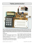
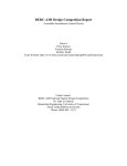
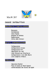
Antenna Rotator Controller
A stand-alone or PC-controlled rotator controller with true azimuth indication & control
D
uring the last VHF contest I came to the realization that my portable station was in
dire need of an antenna rotator. As a single operator I found myself caught in the
frantic pace of manually aiming antennas, working contacts, and logging duties.
After the contest, I resurrected my old TV antenna rotator from the garage and did a quick
check to assure that it was still working. While it was hooked up, I taped a GPS on top of
the rotator and compared the controller and GPS readings for several rotations. I was
surprised to discover that not only were the controller indicator lines off by as much as 25°,
but the controller also had poor repeatability. This discovery led me to think about building
a new controller with better accuracy. While searching the internet I came across a compass
sensor that senses the earth’s local magnetic field and outputs a 0-359° signal. If the sensor
was mounted on the mast I could read the rotator’s magnetic position. A simple math
routine could then add my local declination to the magnetic reading and display true
azimuth. Intrigued, I decided to build a prototype to test the idea.
The Antenna Rotator Controller (ARC) was successfully built and debugged over the next
several months and has proven to be a valuable asset to my station. It features a back-lit
LCD displaying the current azimuth, target azimuth, rotator status, and control input. It uses
software defined limits to restrict the rotation to 0-359° and features motor overload
protection. The ARC is not an add-on unit as it replaces the existing controller and supplies
power for the rotator motor, microcontroller circuitry, and compass sensor. The
microcontroller program is easily customized to the builder’s magnetic declination using
free software.
The ARC is unique in that it senses, displays, and controls to the earth’s true magnetic field.
The compass sensor, mounted in a waterproof enclosure, is attached to the mast and sends
its signal to a microcontroller. The ARC can receive azimuth commands from its internal
keypad, MixW1, or ARC VB (a custom grid square program) and will control many low
cost 24V rotators to a level of precision not found in the original controller.
Rotator (Magnavox M61415)
The antenna rotator used in this project is representative of the light duty single-axis
rotators that employ a 24VAC motor. These rotators are usually north-centered and feature
a mechanical stop between 359° and 0°. Comparable models from Channel Master, Gemini,
Philips, Radio Shack, and Zenith work well for small VHF antenna arrays with at least one
company selling the rotator alone for $452.
Antenna Rotator Controller, KG4JJH
1 of 14
Microcontroller, U1 (Cubloc CB220)
A new type of microcontroller is available that combines Basic programming with PLC
(Programmable Logic Controller) ladder logic. The chip features two serial ports, 16 I/O
ports, 80K flash memory, eight 10-bit A/D analog inputs, I2C bus, and three 16-bit PWM
analog outputs in a 24 pin DIP that is pin compatible with the Basic Stamp BS2. Serial port1 is dedicated to the LCD display and serial port-2 is shared between program downloading
and computer control. The power requirement at 5VDC is 40mA. The chip has a built-in
5V regulator that allows it to run from 5.5 to 12VDC power sources.
Keypad and Controller, M1 & M2 (Cubloc P02007 & U07008)
A 16-button keypad and controller provides operator input to U1. U1 has a dedicated port
for keypad inputs and can create interrupts when a key is pressed, simplifying the
programming. The keys are labeled using dry transfer lettering or labeling machine by
removing the clear key covers and applying the labels.
Compass sensor, M3 (Devantech CMPS03)
This 2-axis compass sensor was designed for use in robots as an aid to navigation. The
module uses two Philips KMZ51 magnetic field sensors, which are sensitive enough to
detect the earth’s magnetic field. The output from two sensors mounted at right angles to
each other are used to compute the direction of the horizontal component of the earth’s
magnetic field. The outputs are pulse width modulation or I2C bus, and the power
requirement is 5VDC@15mA. The I2C bus is used in this application.
I2C Bus Extender, U2-U3 (82B715)
Due to cable loading capacitance the I2C bus is restricted to a maximum distance of 12 feet.
In this application the compass sensor will be mounted up to 100 feet away on the antenna
mast. By adding a bus extender chip at each end of the cable, distances up to 4000 feet are
possible. A 100-foot length of twisted-shielded 2-pair cable connects the compass sensor to
the ARC.
LCD Display Module, DS1 (Cubloc CLCD420-B)
This module features a blue 20x4 digit back-lit LCD display with communications via RS232 or I2C bus. The Cubloc I2C bus normally supports multiple devices, but when used for
displays only one device is permitted. Therefore, the display uses channel-1 of the
microcontroller’s two RS-232 ports. Set the module’s baud rate to 115200 on the rear by
setting DIP switches 1, 2 and 3 to ON. The power requirement with the backlight on is
5VDC@100mA.
Power Supply
Transformer T1 provides 24VAC to the rotator motor and 12VAC from one side to the
center tap to full wave bridge rectifier D1. Capacitor C1 provides filtering and feeds voltage
regulator U4 to provide 12VDC to U1 and the two relays. The output of U4 feeds voltage
regulator U5 which provides 5VDC to the rest of the circuitry. Both voltage regulators are
mounted on heat sinks to dissipate the heat.
Antenna Rotator Controller, KG4JJH
2 of 14
Rotator Motor Drive & Protection
Digital outputs on U1 ports P8 and P9 turn on transistors Q1 and Q2 to drive relay coils
RLY1 and RLY2, respectively. The relay contacts then switch one side of a non-polarized
capacitor (C4) to each of the two motor windings to obtain CW and CCW rotation. Diodes
D2 and D3 serve as spike suppressors when the coil is turned off, protecting Q1 and Q2.
Current transformer T2 monitors the motor current and outputs a proportional AC voltage.
A one-turn loop of #18AWG insulated wire through the coil serves as the transformer’s
primary winding. The secondary is sent to a full wave rectifier formed by D4-D7. Filter
capacitor C11 and load resistor R10 converts the AC voltage to DC. An A/D converter in
U1 then translates this voltage to a value of 0-1023. Whenever the current exceeds a preset
amount in software (750) the ARC removes power from the rotator motor and displays
“Stalled” in the status line. This feature protects the motor from damage in the event that
the rotator attempts to rotate past its stops or is otherwise unable to turn.
Construction
The circuit layout is not critical and can be built on perf-board with point-to-point wiring
using component leads and small gauge wire-wrap wire. Terminal strips serve as a
convenient transition point between perf board wiring and external components.
Transformer T1 and capacitor C4 are mounted on top of the enclosure’s internal chassis. To
minimize the amount of metal around the compass sensor, nylon hardware is used for the
standoffs and the compass sensor perf board is mounted in a plastic enclosure. A cable grip
clamp is used on the compass sensor enclosure to reduce the risk of water leakage. SW1
turns power on and off, SW2 selects keypad or computer input, and SW3 is used to
calibrate the compass sensor.
Programming
To program the microcontroller, download Cubloc Studio4 from the manufacturer’s
website. Install this free software on your PC and practice opening, editing, and saving
programs while connected to U1 (CB220). If your PC doesn’t have a serial port, use a USB
to serial adapter such as the IOGear GUC232A, and set up the communication port in
Cubloc Studio to match your port number. When you first connect your PC to the CB220
the software may prompt you to do a firmware download from their website. This is a good
idea as it will install the latest firmware and bug fixes to the microcontroller. The firmware
version used for this project is version 2.2.f.
Next, download the ARC.zip5 file which contains two Cubloc files. Look up the desired
magnetic declination and direction (E or W), and inclination from a Magnetic Field
Calculator6 and jot these down. To customize the program for your declination follow the
instructions in program lines 286-288 and then edit line 290 using Cubloc Studio. Save the
program and then load it into the CB220 by typing Ctrl R. Unplug the serial cable and the
microcontroller is ready to run on its own.
Antenna Rotator Controller, KG4JJH
3 of 14
Software Features & Operation
Upon power up, the display will show the title, author, software version, and initialize
program parameters. During initialization, the target azimuth is set equal to the current
azimuth. All values are updated every 200mS or less and displayed during rotation. The
displayed values are:
o
o
o
o
Azimuth: 0-359° (current true azimuth)
Target: 0-359° (desired true azimuth)
Status: Idle, Turning CW, Turning CCW, Jog CW, Jog CCW, and Stalled
Control: Keypad or PC
The output of the compass sensor is 0-3599, with the last number representing tenths of a
degree. True azimuth is calculated by adding the user’s local declination value to the
magnetic reading as sensed by the compass sensor. Based on whether the declination is
positive or negative, math routines then add or subtract 3600 to prevent the true azimuth
from reading greater than 359 or less than zero. After the declination math has been
performed only the first three digits are displayed.
When SW2 is switched to KEYPAD the controller operates in stand-alone mode and
receives all commands from the built-in keypad. When CLR is pressed the Target value
clears and the user enters a three digit azimuth. Azimuth values are restricted to values from
000° to 359°, and values less than three digits (i.e. 8°) must be preceded by zeros (008°).
Pressing CLR at any time clears the entered value and waits for a new value. If an invalid
azimuth has been entered and GO is pressed, the target azimuth will clear and the display
backlight will flash several times and wait for a new target. When a valid Target azimuth
has been entered and GO is pressed, the rotator will begin turning to the desired azimuth.
Pressing STOP at any time during rotation cuts power to the rotator. Pressing GO continues
turning to the Target. Pressing JOG CW or JOG CCW will move the rotator approximately
2° in each respective direction. The RST button resets the microcontroller and reinitializes
the software. If the rotator is unable to travel in the desired direction the motor current will
increase. Power is then removed from the motor and the status line will indicate STALLED
for several seconds.
When SW2 is switched to PC, the controller receives azimuth target values from MixW via
J1, and rotator movement is controlled from the program. MixW sends the target azimuth to
the ARC, starts rotation, and then simulates rotator movement with on-screen graphics (see
Figure 1). Rotator status can then be monitored on the ARC display which displays the
same information as it does in KEYPAD mode except the keypad is nonfunctional.
To set up the ARC in MixW (Figure 1), first ensure that your latitude and longitude have
been entered (Configure/Personal Data). Then, turn on the World Map display
(View/World Map), select Yaesu rotator (Configure/Rotor/Yaesu), and serial port number
(Configure/Rotor/Settings). Set the baud rate to 38400, 8 data bits, no parity, 1 stop bit, and
the azimuth offset to 0. When a call sign is entered the short path azimuth is displayed on
the world map. Click on the World Map Up Arrow (lower left) to move to the short path
azimuth and the Down Arrow (lower right) to move to the long path azimuth. There is also
Antenna Rotator Controller, KG4JJH
4 of 14
a command to turn to a user specified azimuth (Configure/Rotor/Turn To). Clicking on the
CCW and CW arrows at the top left and top right will jog the rotator 2° in its respective
direction. A black line emanating from the center of the globe simulates the rotator turning
by moving approximately 1° per second. This speed is very close to the rotator’s actual
turning speed.
This rotator does not have braking, so to prevent the rotator from exceeding the target
azimuth, rotation stops when the azimuth is within 2° of the target. The microcontroller
programming port and the MixW port are shared, so if the MixW cable is connected when
starting MixW the ARC will reset.
Figure 1
ARC VB (Figure 2)
A custom grid square program was written to control the ARC from a computer serial port.
It supports Yaesu and Orion rotator formats, com ports 1 through 12, and communicates at
38400 baud, 8 data bits, no parity, and 1 stop bit. Enter your grid square, the target grid
square, and click the “Calculate” button to see the azimuth and distance to target. Then,
click on “Rotate” to rotate to the target heading. Once there, click on “Jog CW” or “Jog
CCW” to fine-tune the azimuth in 2° increments.
Figure 2
Antenna Rotator Controller, KG4JJH
5 of 14
Accuracy and Calibration
Like a compass or GPS, the compass sensor must be level to get accurate readings.
Similarly, keep the unit away from magnets, motors and large metallic objects to reduce
interference. The resolution of the compass sensor is listed as 0.1°, but due to calibration
accuracy and local interference the accuracy is +2°.
Calibration of the CMPS03 compass sensor only needs to be done once - the calibration
data is stored in EEPROM on the compass module. The module has been factory calibrated
to an inclination of 67°, and if your location is close to this you may want to try the
compass without re-calibrating7. The inclination at my QTH is 65°, so I chose to recalibrate. You will need a flat level surface free of motors, magnets, and metal and a decent
compass to perform the calibration. I found it helpful to place the sensor and reference
compass on a rotatable board and align them along parallel drawn lines. The compass
points can be set in any order, but all four points must be calibrated to magnetic compass
points. With the compass sensor level, press SW3 and hold it down for one to two seconds
at each compass point, N, E, S, and W. To aid in calibration, I added an LED from pin 5 to
+5VDC through a 390Ω resistor. The LED will light when calibration is in progress.
Setup and Operation
Connect all cables between the ARC, rotator, and compass sensor. Turn the ARC on and set
the rotator to 0° by moving CCW until the rotator will not turn. Secure the rotator to a
stationary pipe and make every effort to ensure that it is plumb. Mount the mast on the
rotator loose enough so that it can be manually turned. Mount the compass sensor on the
mast in an area away from large metallic objects or motors. (For installation on the side of
an RV or camper, mount the compass sensor 2-3 feet above the vehicle.) Next mount the
antenna(s) and align the antenna beam direction and compass sensor so they are aligned to
true north. Tighten the rotator’s U-bolts on the mast and confirm that the displayed azimuth
is 0°. Finally, perform a trial run to ensure that the mast is turning unobstructed.
A newly constructed 222 MHz transverter and Yagi provided an opportunity to test the
ARC in the upcoming 2008 ARRL January VHF Sweepstakes. With the rotator mounted on
a length of galvanized pipe driven into the ground, the compass sensor and antenna were
mounted on a painter pole and extended to 16 feet. Although conditions were less than
optimum, the ARC performed well.
Subsequent testing was performed with the arrival of warm weather. The compass sensor, 3
VHF/UHF Yagi’s, and a 6m Moxon were mounted on a fiberglass mast (Max-Gain
Systems MK-6). The rotator had no problems turning this 35 pound load and the ARC
repeatedly rotated to the target azimuth within 2° from either direction. Additional testing
with 10 through 17m wire Moxon antennas worked equally well. No RFI problems were
observed using power levels up to 100 watts.
One problem was observed during clockwise rotation to azimuths near 359°. If the compass
sensor indicates 0° or higher due to high winds or mast slippage, the ARC will misinterpret
the next command. It will attempt to rotate clockwise and the mechanical stop between
359° and 0° will prevent this. However, no damage will result because the motor overload
Antenna Rotator Controller, KG4JJH
6 of 14
protection removes power. The easiest solution is to jog counter-clockwise until the
azimuth is 359° and then move to the next target. When time permits, re-align the compass
sensor and rotator to 0°.
Summary
The ARC has a level of accuracy and repeatability not available from the rotator’s original
controller. It is unique among all commercial controllers in that it continually senses the
earth’s magnetic field instead of relying on a potentiometer, and when connected to one of
the light duty rotators it presents an economical package that works well for small beams.
So, if you have an unused rotator lying around or just want to update the controls, the ARC
is ideal as it will free the busy contest operator to do other tasks. I am looking forward to
the next VHF contest as well as general HF use with this new setup. Good luck and happy
building!
73,
Allen Baker, KG4JJH
http://www.kg4jjh.com
[email protected]
Notes
1. MixW, Digital Mode Software, N. Fedoseev (UT2UZ), D. Nechitailov (UU9JDR);
http://mixw.net
2. Magnavox M61415 Replacement Rotor Motor, Part # M-61415, Summit Source;
http://www.summitsource.com/antenna-rotor-motor-rotator-antennacraft-universal-3wire-replacement-for-philips-magnavox-m61415-steren-automatic-signal-locatoroutdoor-offair-tv-antenna-rotator-replacement-rotor-motor-part-m61415-p-9152.html
3. ExpressPCB; http://www.expresspcb.com/
4. Cubloc Studio, Comfile Technology.; http://www.comfiletech.com/
5. KG4JJH website; http://kg4jjh.com/program/ARC.zip
6. Magnetic Field Calculator, National Geophysical Data Center;
http://www.ngdc.noaa.gov/seg/geomag/jsp/IGRFWMM.jsp
7. Calibrating the CMPS01, CMPS03 Robot Compass sensors;
http://www.robot-electronics.co.uk/htm/cmps_cal.shtml
Antenna Rotator Controller, KG4JJH
7 of 14
Figure 3
Antenna Rotator Controller, KG4JJH
8 of 14
KG4JJH
ANTENNA ROTATOR CONTROLLER
1
2
3
GO
4
5
6
STP
7
8
9
CLR
JOG
CW
0
JOG
CCW
RST
J2
J3
J1
F1
PC
POWER
KEYPAD
FRONT VIEW
REAR VIEW
DESIGN: KG4JJH
09/23/07
TESTED: KG4JJH
01/15/08
KG4JJH
ANTENNA ROTATOR CONTROLLER
ASSEMBLY
SCALE: 1:1
SHEET 1 OF 5
Figure 4
Antenna Rotator Controller, KG4JJH
9 of 14
REV. 0
ANTENNA ROTATOR CONTROLLER
KG4JJH
1.312
4.094
6.000
1
2
3
GO
4
5
6
STP
7
8
9
CLR
4.250
3.000
JOG
CW
0
JOG
CCW
1.750
RST
0.750
Ø 0.875
J2
J3
J1
1.000
F1
POWER
PC
0.375
KEYPAD
0.375
FRONT VIEW
REAR VIEW
DESIGN: KG4JJH
09/23/07
TESTED: KG4JJH
01/15/08
KG4JJH
ANTENNA ROTATOR CONTROLLER
LAYOUT
SCALE: 1:1
SHEET 2 Of 5
Figure 5
Antenna Rotator Controller, KG4JJH
10 of 14
REV. 0
J1
F1
J3
J1
F1
J2
J2
J3
3
~
+
+
C1
4
5
D4
D5
D6
D7
6
D1
+ C11
T1
T1
2
-
1
~
TS3
TS3
T1
C4
T2
R12
9
10
TS2
U4
7
8
RLY2
RLY1
C5
+
C2
6
D2
T1
C4
4
R8
R9
Q2
C6
5
+
C4
D3
Q1
U5
C3
C7
R6
R2
2
R1
R7
3
C8
U2
1
U1
R5
2
3
4
5
6
7
8
9
10
11
12
TS1
1
KEY
PAD
SW
1
SW
2
CHASSIS TOP VIEW
SCALE: 1:1
CHASSIS SIDE VIEW
SCALE: 1/2:1
DS1
CHASSIS BOTTOM VIEW
SCALE: 1:1
DESIGN: KG4JJH
09/23/07
TESTED: KG4JJH
01/15/08
KG4JJH
ANTENNA ROTATOR CONTROLLER
CHASSIS & PERF BOARD DETAILS
SCALE: NOTED
SHEET 3 OF 5
Figure 6
Antenna Rotator Controller, KG4JJH
11 of 14
REV. 0
1-3/4" RESIN SUPPORT BLOCK CLAMP
DX ENGINEERING DXE-RSB-I13400
M1
CMPS03
U1
3
4
N
5
3
4
R4
R3
R4
2
2
DSP2
C9
R11
1
M1
CMPS03
SW3
C9
DSP2
U1
1
C10
R11
R3
SW3
C10
5
ANTENNA MAST
PERF BOARD ASSEMBLY
3.50
EXISTING ENCLOSURE HOLE
CORD-GRIP
1" X 1" X 3.5"L X 1/8"THK
ALUMINUM ANGLE
VIEW A-A
09/23/07
TESTED: KG4JJH
01/15/08
KG4JJH
ANTENNA ROTATOR CONTROLLER
MAGNETIC SENSOR DETAILS
A
A
DESIGN: KG4JJH
SCALE: 1:1
SHEET 4 OF 5
Figure 7
Antenna Rotator Controller, KG4JJH
12 of 14
REV. 0
TO
CONTROLLER
P3
P2
ROTATOR
COMPASS
MODULE
MAST
PIPE FLOOR
FLANGE
PIPE NIPPLE
DESIGN: KG4JJH
09/23/07
TESTED: KG4JJH
01/15/08
KG4JJH
ANTENNA ROTATOR CONTROLLER
MOUNTING DETAILS
SCALE: NTS
SHEET 5 OF 5
Figure 8
Antenna Rotator Controller, KG4JJH
13 of 14
REV. 0
Antenna Rotator Controller Materials List
Part
Qty
Description
Part Number
Source
U1
1
Microcontroller, 24-Pin DIP, Cubloc CB220
U2-U3
2
IC, I2C Bus Extender, 8-Pin DIP, Philips P82B715
U01002
comfiletech.com
C7-P82B715
U4
1
Voltage Regulator, TO-220, 12V@1A
511-L7812ACV
comfiletech.com
mouser.com
U5
1
Voltage Regulator, TO-220, 5V@1A
511-L7805ACV
mouser.com
M1
1
Keypad Module, 4x4, Cubloc (Note-2)
P02007
comfiletech.com
M2
1
Keypad Controller Module, Cubloc (Note-2)
U07008
comfiletech.com
M3
1
Compass Module, Daventech
DS1
1
Display, LCD, 20x4, Cubloc CLCD420-B (Note-2)
T1
1
Transformer, Primary 120VAC, Secondary 24VAC CT@2A
RLY1-RLY2
2
Relay, 12VDC, SPDT, 10A Contacts
Q1-Q2
2
Transistor, NPN, 2N3904
D1
1
Diode Bridge,
D10-D11
2
Diode, 1N4148
SW1
1
SW2
CMPS03
D08001
snailinstruments.com
comfiletech.com
553-F192X
893-812H1CS12VDC
mouser.com
512-2N3904_D10Z
mouser.com
583-DB107
mouser.com
512-1N4148
mouser.com
Switch, Toggle, DPDT
108-1MD1T2B3M1QE-EVX
mouser.com
1
Switch, Toggle, SPDT (Note-2)
108-1MS1T2B3M1QE-EVX
mouser.com
SW3
1
Switch, Pushbutton, Momentary
10PA018
mouser.com
F1
1
Fuse Holder & 1A Fuse
441-R3-13-GRX
mouser.com
2
Heatsink, TO-220
mouser.com
C1
1
Capacitor, Electrolytic, 1000uF@50V
707-821902B00
140-XRL50V1000-RC
mouser.com
C2-C3
2
Capacitor, Electrolytic, 1uF@50V
140-XRL50V1.0-RC
mouser.com
C4
1
Capacitor, Electrolytic, Non-Polarized, 160uF@125VAC
C5-C10
6
Capacitor, Ceramic, 0.01@50V
87F1264
581-SR215C103JAR
mouser.com
R1-R5
5
Resistor, Metal Film, 1/4W, 4.7K
271-4.7K-RC
mouser.com
R6-R7
2
Resistor, Metal Film, 1/4W, 330
271-330-RC
mouser.com
R8-R9
2
Resistor, Metal Film, 1/4W, 10K
271-10K-RC
mouser.com
-
mouser.com
newark.com
R10
1
Resistor, Metal Film, 1/4W, 1K
271-1K-RC
mouser.com
R11
1
Resistor, Metal Film, 1/4W, 390
271-390-RC
mouser.com
J1
1
Connector, DB-9, Female, Chassis Mount
152-5109
mouser.com
J2
1
Connector, XLR, 3-Pin, Female, Chassis Mount
565-5113A
mouser.com
J3
1
Connector, XLR, 5-Pin, Female, Chassis Mount
565-6854
mouser.com
P2
1
Connector, XLR, 3-Pin, Male Plug
565-6851
mouser.com
P3
1
Connector, XLR, 5-Pin, Male Plug
565-5126A
mouser.com
TS1-TS2
2
Terminal Strip, 12 Contact, PCB Mount
158-P02ELK508V12-E
mouser.com
TS3-TS4
2
Terminal Strip, 5 Contact, PCB Mount
158-P02ELK508V5-E
mouser.com
-
1
Enclosure, Controller, Bud PortaCab WA-1540
-
1
Chassis, Controller, Bud AC-402
-
1
Enclosure, Azimuth Sensor, Hammond 1555EGY
-
1
Power Cord, 6 ft.
-
AR
-
1
Socket, 24-Pin DIP
-
2
Socket, 8-Pin DIP
-
50
Cable, Rotator, 3-Conductor, 20 AWG, Radio Shack
-
50
Cable, Twisted-Shielded 2-Pair, Alpha 5472C
-
1
-
WA-1540
adproductsco.com
AC-402
adproductsco.com
546-1555EGY
mouser.com
173-53101-E
mouser.com
Perf Board, 0.1-inch hole spacing
mouser.com
575-11044624
mouser.com
575-893308
mouser.com
15-1150
602-5472C-100
mouser.com
Strain Relief, Controller Enclosure, Heyco
836-3210
mouser.com
1
Strain Relief, Sensor Enclosure, Heyco
836-3207
mouser.com
-
4
Standoff, Hex, 0.25x0.50, Aluminum
534-2203
mouser.com
-
16
Screw, 4-40NCx0.25
5721-440-1/4SS
mouser.com
-
1
Clamp, Resin Support Block, 1-3/4"
DXE-RSB-I13400
radioshack.com
dxengineering.com
Table 1
Antenna Rotator Controller, KG4JJH
14 of 14