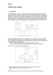
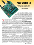
1
“QuickieLab” Assembly & User Manual
… a BASIC Stamp platform for ham radio experiments
Figure 1: The QuickieLab is a BASIC Stamp-powered experimenters’ platform with a 16x2 character LCD for data and status display, keypad
for numeric data and command entry, general purpose input/output devices (potentiometer, pushbuttons, LEDs, speaker), a frequency counter,
A/D and D/A converters, a digital pot and an RS-232 serial port for downloading of Basic program experiments. Provision is also made to
accommodate an AD9850 DDS DaughterCard, separately available from the NJQRP Club. The Stamp’s sixteen input/output pins may be
jumpered to an “experimenter’s plugboard” for temporary addition of circuit components that work with the downloaded software in the BASIC
Stamp to perform the experiments. [A prototype PC board is shown here. The production version is soldermasked and silkscreened to assist in
assembly.]
INTRODUCTION
bed for experimentation, measurement and simple control.
Further, we thought it would be great if this experimenters’
platform were tightly coupled with the string of “N2CX
Quickies” presented in each issue of QQ magazine. This
would provide Joe with a computing module to help illustrate
his points and the readers with a quick and easy way to
reproduce the Quickie material. Hence the name of this
project was born … the QuickieLab.
Great feedback is regularly received now from readers on the
latest string of microcomputing projects in QRP
Homebrewer and QRP Quarterly magazines. It’s very
gratifying and encouraging to know that many QRPers are
interested in these digital projects.
When considering even more useful projects that QRPers can
easily build right now, the light bulb clicked on once again
over a lunch with Joe Everhart, N2CX. We decided then that
a perfect project would be one that provides a reusable test
QuickieLab Assembly & User Manual, v1.0
1
Copyright 2003, G. Heron N2APB
THE BASIC STAMP
As mentioned, a number of common I/O devices are
provided on the QuickieLab board for use in the various
experiments. Three pushbuttons and three LEDs are provided
for simple input and output controls and indicators.
Sometimes the most instructive experiment is to press a
button and see a corresponding LED be illuminated under
program control. A built-in potentiometer is provided and is
quite useful as a control that delivers a continuously variable
0-255 binary input to the Basic program. A program can read
the pot and adjust a software algorithm based on the specific
setting. A simple D-to-A converter is provided to produce a
DC voltage from 0-to-5V for controlling other hardware
under software control. And lastly, a speaker is provided to
enable the Basic program to output an audio tone that can
range from 200 Hz up to 10 KHz. Can’t you just imagine a
an upcoming Joe’s Quickie application using this speaker to
produce an audio dip when measuring SWR?!
The QuickieLab is a 4.5” x 6” printed circuit board with
keypad, LCD, switch input and LED output capabilities built
around the popular BASIC Stamp processor from
Parallax.inc. The Stamp was selected because of its easy to
program BASIC language and its simple hardware interface
– just connect +5V to this Stamp chip and you can download
a BASIC program from your PC to wiggle the output pins
and read the input pins as desired.
Readers wishing to follow along with N2CX and his BASIC
language experiments could certainly purchase one of the
many fine Stamp -based experimentation boards from
Parallax.com and have a ready-to-go hardware platform with
most of the capabilities described here. However, one could
save quite a few pennies by building the QuickieLab from
the plans in this article and end up with a more capable
platform that is specifically geared to the Joe’s Quickie
experiments coming in future installments.
Each of these built-in I/O devices is wired to a specific I/O
pin of the Stamp through pinheader P1. When the
corresponding pins of P1 are jumpered with configuration
blocks, the respective signals are wired directly to I/O pins
on the Stamp. In this way you could easily configure the
QuickieLab to use its built-in components for experiments
without necessarily using additional components on the
plugboard. When a given built-in I/O device is not needed
for the current experiment, its pins on P1 can be left open
and the Stamp’s I/O pin on J10 may be jumpered over to
something else on the plugboard.
Refe rring to the schematic, you can see that the QuickieLab
is based on use of a BASIC Stamp microcontroller.
The Stamp merely needs to be powered with 6-to-12V dc
from the QuickieLab’s connector J1 and this self-contained
“system on a chip” is ready to go. It contains an onboard 5V
regulator for its computing logic and its own RS-232 levels
for serial port connection to a PC. Further, the Stamp
contains an internal non-volatile memory that allows
retention of the software program even after power is
removed. With this capability the QuickieLab can be
programmed once (i.e., it’s software program needs only to
be downloaded once from the PC), and it can forevermore
operate independent from the PC umbilical cord. Take it out
to the field with an appropriate battery supply or to your
buddy’s house and it’ll operate the same as it last did on your
bench!
I/O EXPANDER
Perhaps the most attractive feature of the QuickieLab, as
compared to commercially-available Stamp boards, is the
custom-designed I/O expansion processor U2. Readers of the
Digital QRP Homebrewing column in QQ will recognize the
SX-28 microcontroller used for I/O expansion here as also
being used in the PSK31 Audio Beacon and Badger
smartbadge projects. This time I programmed the SX-28 to
enhance the QuickieLab by having it serve as an intermediate
processor that helps in the input and output of some
additional built-in components. The IOX project website
provides complete details on interfacing and using the I/O
Expander, but here’s a quick overview of the function
provided in this versatile controller.
I/O PINS DO ALL THE WORK
The main purpose of any microcontroller is to input various
signals, do some computations based on those signals, and
then output other signals based on those computations. Thus
the Stamp’s 16 I/O pins are of great interest and utility to us
in the QuickieLab. Each of the I/O pins is under software
control and can be used to read the state of pushbuttons and
keypad actuations, as well as to send data to human-readable
devices like the LEDs and the LCD. The I/O pins are wired
to a jumper block J10 located directly above the plugboard
and the user may jumper any of them to components placed
on the plugboard. In this way, the components called out in
the experiment may be temporarily “wired” to the Stamp and
controlled by the software program. For example, you could
mount a diode, resistor and a couple of capacitors on the
plugboard, jumper the output of that network to the built-in
A/D converter (see following section) and have yourself a
rudimentary-but-useful RF voltmeter. Of course you’d have
to have the Voltmeter software loaded on the Stamp from the
N2CX Quickie website – Joe intends on having many such
software programs and application notes available for the
QuickieLab.
QuickieLab Assembly & User Manual, v1.0
Serial LCD Display Driver – The SX-28 accepts serial
commands from the BASIC Stamp to display the specified
ASCII character directly, or a command character to control
the cursor position and other LCD functions like clear
display and scroll control. The SX-28 duplicates the simple
command structure found in other “serial LCD” controllers,
allowing the QuickieLab programmer (i.e., you) to easily
display messages to the LCD display. You can clear the
display, home the cursor, control scrolling and blinking, and
simply display characters all by means of a serial output
command from the BASIC Stamp software you’ve written.
Frequency Counter – Another unique feature of this I/O
Expander chip is its ability to measure frequency. Since this
fast SX processor is sitting idle most of the time waiting to
be commanded by the Stamp to display characters, I dropped
2
Copyright 2003, G. Heron N2APB
in a tried-and-true software routine that samples the signal on
the RTCC pin and determines its frequency. Thus when the
Stamp commands a frequency measurement, the SX
processor sends back certain data that represents the
frequency of the input signal up to 30 MHz. This is a pretty
useful feature for a QuickieLab such as ours!
follow that may help you assemble the components to the PC
board.
IC sockets should be used for all integrated circuits.
Single in-line 0.1”-spaced female sockets are used
throughout the PC board to provide “patchable access”
between the various signals and the additional components
that you will plug into the experimenter’s plugboard. These
female sockets are also used to connect the LCD and keypad
modules, which are held up off the board with standoffs and
plug into connectors on the PC board to facilitate easy access
to components beneath them during the construction and test
phases. The strips are purchased in 36- or 72-position
lengths and must be snipped off to create the individual
pieces for each connector. When snipping off a length of the
strip, you will likely lose (destroy) one position and need to
file down the rough end to make it a clean edge.
Alternatively, a fine-tooth hobby saw may be used to create
the individual pieces without losing a connector position in
the process.
A-to-D Converter – Since it is important in most of our ham
experiments to read an analog voltage of some sort, we felt it
would great to add a simple 8-bit A/D converter as part of the
built-in arsenal of components. The I/O Expander interfaces
to the ubiquitous ADC0831 chip and the BASIC program in
the Stamp can issue an ADC command instructing the analog
conversion to be done. The 8-bit value is then returned to the
Stamp controller for possible computation and display.
Keypad – Yet another important I/O component contained in
the I/O Expander chip is that of the software driver and
hardware interface to a keypad. Useful for numeric and
command entry, this 4 row x 3 column matrix keypad is
constantly scanned by the SX controller. Whenever a
keypress is detected, a message is sent to the main BASIC
program in the STAMP controller and specific action can be
taken. In this way, the programmer (i.e., N2CX with his
application note software, or you with your own software
experiment) may input data, set frequencies to be later
output, etc.
Stamp I/O signals socket -- The socket strip containing the
Stamp I/O pin signals is located directly to the left of the
plugboard to allow the user to easily place a wire jumper
from any given BS2 signal to a component on the plugboard.
Built-in I/O Header -- Jumpers placed along a dual row 0.1”
pinheader to patch in the built-in IO devices located above
the plugboard.
Digital Potentiometer – The final built-in I/O device
controlled by the I/O Expander is a non-volatile “digital
potentiometer”. This device is essentially an electronic pot
that can be adjusted under program control to move its wiper
to be at any of 100 positions. If, for example, this digital pot
were jumpered into the feedback loop of an op amp on the
plugboard, your BASIC Stamp program could output a
command to the I/O controller to adjust the pot up or down
to change gain of the amplifier stage. This is a pretty neat
capability to have in our experimenter’s platform!
Speaker -- The thin, 16-o r-32-ohm speaker is glued to the
bottom side of the PC board and its leads are soldered to the
noted pads.
Rubber feet should be attached to the bottom of the PC
board to allow it to stand comfortably on your work table
when in use.
LCD – The QuickieLab PC board was layed out using a
popular 2x16 LCD from BG Micro. This part was very
inexpensive and in large supply at the time of the kit design.
However from time to time, specific discount/surplus parts
may be temporarily unavailable and a homebrewer may need
to use displays from other manufacturers. In general any
2x16 or 2x20 character LCD that uses the HD44780
controller and has a 4-bit interface available will functionally
work with the QuickieLab board and software. Other
manufacturers’ display form factors will likely be different
and you will need to make up a simple 10-wire harness to
connect the display to the appropriate pads on the board
connector J13. Just adapt your specific display to the
QuickieLab and you’ll be in business!
DDS DaughterCard – Provisions are made on the
QuickieLab to accommodate the newest addition in the
HC908 Digital Breadboard project family - a DDS
daughtercard. This small board contains the AD9850 Direct
Digital Synthesis chip, its oscillator and the low pass output
filters that all conspire to produce very precise and low-noise
frequencies from the sub-hertz basement up to 30 MHz. The
1”x 2” daughtercard plugs into socket J6 on the QuickieLab
and enables the homebrewer/programmer to generate a very
precise and accurate signal source. It can be useful as a VFO,
a test signal source, a local oscillator in a test receiver or
even as an audio oscillator when patched into the built-in
speaker on the QuickieLab.
Voltage Regulator VR1 – If you use the heatsink
(recommended), it would be good to drill a 1/8” hole at the
marked location and screw the heatsink and VR1
combination to the pc board. You should also use thermal
grease between VR1 and the heatsink, as this will ensure a
good thermal connection and give you the widest safety
factor for power dissipation.
CONSTRUCTION
Building up the QuickieLab is straightforward. The list of
parts is provided in this manual and components are easily
acquired from Mouser Electronics, Dig -Key and the NJQRP
Club. You might even have some of these common parts
already in your own junkbox.
Assemble all components on the PC board by carefully
following the Parts Layout diagram. Some specific notes
QuickieLab Assembly & User Manual, v1.0
3
Copyright 2003, G. Heron N2APB
Potentiometer R10 – You can use any mini pot for this
component. Just glue it to the board and wire its three
connections to the respective pads nearby the component.
Any implementation of a Stamp microcontroller might be
seen as an expensive computing solution. The BASIC Stamp
starts out at $49, and the other components add up from
there. A complete QuickieLab might well cost the
homebrewer over $100 by the time it’s completed. But
“expensive” is a relative term and some homebrewers will
likely see this investment as valuable in terms of its
educational and long-time reusable nature.
ERRATA
1) “J12” was inadvertently used as the reference designator
for two connectors: the Keypad and the Digital Pot.
2) Pin 1 of the LCD connector J13 was inadvertently left
ungrounded. You should ground this square pad by placing a
short jumper on the bottom side of the board from from the
pad to the grounded side of the trim potentiometer next to it.
The QuickieLab is not a performance-oriented or extensible
microcomputing platform. A very limited number of I/O pins
limits how many hardware components can be connected at
one time. Further, the effective speed of the Stamp is
significantly slower than the HC908 Digital Breadboard
project or any other native-language PIC processor, mainly
because the Stamp interprets its high-level BASIC
commands individually at run time, greatly slowing down its
overall computing process. In contrast, the HC908 Digital
Breadboard project is a far better choice for a flexible and
dedicated high-performance control and measurement piece
of equipment for your bench.
USING THE QuickieLab
The QuickieLab is first and foremost based on the BASIC
Stamp. The vendor of this ingenious device (Parallax.com)
provides an excellent development suite to support hobbyists
in their programming and use of the Stamp. When you
purchase the microcontroller from Parallax, you can request
a CD-ROM containing software for your PC that allows you
to create/modify your BASIC programs and download them
to the Stamp contained on the QuickieLab. Otherwise, all
software contained on the CD-ROM is also available for free
download from their Stamp web pages at www.parallax.com.
However even with these limitations, the QuickieLab is a
great educational solution for quick-and-easy experiments
that don’t require lots of high speed operations. N2CX
regularly tells me how utterly cool it is to be able to program
an algorithm into the QuickieLab and see immediate results.
Parallax “PBASIC” commands are tailored to real time
control of simple hardware devices and there are many useful
extensions to the language which are of great value to
homebrewers. The CD-ROM also contains many sample
programs illustrating basic operation of the commands and
chip features.
Any way you look at the QuickieLab, it’s easy to build, fun
to use and you can bet that we’ll be seeing lots of
applications for it in future “Joe’s Quickies”. And for
starters, have a go at the “Audio Voltmeter” application
elsewhere in this issue!
You can quickly test your assembled QuickieLab by running
a BASIC software program provided on the project website.
This “QuickieLab Monitor Program” exercises most of the
board’s features and customizing the Monitor program is an
excellent starting point for you in making your own
programs and experiments.
PARTS LIST
BASIC Stamp IC – U1 www.parallax.com
I/O Expander IC – U2, Y1 resonator & PCB – NJQRP Club
A/D converter, – U3, Digi-Key ADC0831CCN- ND
NV Trim Pot IC – U4, Digi-Key DS1804-100-ND
LCD – 16x2 character LCD, BG Micro MDL 16264,
www.bgmicro.com
Keypad – 4 row x 3 column, Digi-Key GH5001-ND
Plugboard – Radio Shack 276-175
RS-232 DB9F connector – J5, D-style, Jameco 104951
Coaxial power connector – 2.1mm , P3, Mouser 163-5004
BNC jacks – J8, J9 , Mouser 523-31-5538-10-RFX
Voltage regulator – 1A 5V, VR1 , Mouser 511-L7805 ABV
Heatsink – Mouser 532-577102B00
Pushbutton (4) -- PB1,2,3,4 – Digi-Key P8075SCT- ND
SIP sockets – J2,3,4,6,7,10,11,12, Mouser 517-974-01-36
Pinheader – 2x12 pinheader, P1, Mouser 517-6121TN
Jumper shunts (16) – 0.1”, Mouser 571-3828155
Speaker – 32-ohm, Mouser 65-AT-42 or RS p/n 273-0093)
Transistor – 2N4401 transistor, Q1, Mouser 512-2N4401
LED (3) – Digi-Key 160-1104-ND
Capacitor – 4.7pF disc, Mouser ____
Capacitor – .0022uF disc, Mouser _____
Capacitor –.1uF mono, Future-Active SR215E104MAA
Capacitor – 1uF electrolytic, Mouser 140-XRL50V1.0
Capacitor – 10uF electrolytic, Mouser 140-XRL16V10
IC socket (2) – 8-pin, Mouser 575-193308
IC socket – 24-pin, Mouser 575-193624
IC socket – 28-pin, Mouser 575-193328
Potentiometer – 10K-ohm, Mouser 31CW401 or 317-2090-10K
Trim Pot – 10K-ohm, Mouser 72-T93XA-10K
Resistor – 220-ohm, Mouser 291-220
Resistor -- 470-ohm resistors (3) – Mouser 291-470
A Users Manual is provided in PDF format on the Parallax
CD to guide first time users through typical BASIC program
creation and debug sessions. A complete PBASIC language
guide is also in the Users Manual for detailed use as a
programming reference.
With all this neat development stuff provided by Parallax,
you can easily have your QuickieLab up and running within
an hour. All you then need to do is download the specialized
QuickieLab Application Notes from the project website
(www.njqrp.org/quickielab), send that specific BASIC
program to your QuickieLab and you’ll be able to keep right
in step with N2CX when he comes out with the next “Joe’s
Quickie” in the pages of QQ.
Any convenient source from 9V to 12V may be used to
power the QuickieLab. The supply current is only about
85ma, so even battery operation is feasible.
LIMITATIONS
The BASIC Stamp as a microcontroller and the QuickieLab
as an experimenter’s platform each has great potential for
instruction and utility on your workbench. However I’d be
remiss not to caution readers about some limitations.
QuickieLab Assembly & User Manual, v1.0
4
Copyright 2003, G. Heron N2APB
Resistor – 1.5K-ohm Mouser 291-1.5K
Resistor – 2K-ohm, Mouser 291-2K
Resistor – 10K-ohm, Mouser 291-10K
Resistor – 100K-ohm, Mouser 291-100K
4) Read all about the BASIC Stamp at the Parallax.com
website (www.parallax.com). All software, application
notes and documentation are free for the download, and
great fun can be had while perusing this vendor’s
website.
NOTES
5) Questions concerning the QuickieLab may be directed to
George Heron, N2APB ([email protected]) or Joe
Everhart, N2CX ([email protected]). We’ll do our
best to help you out as soon as possible.
1) The QuickieLab was designed by George Heron,
N2APB. Copyright 2002 by George L. Heron. All
rights reserved.
2) The QuickieLab project website can be found at
www.njqrp.org/quickielab. It contains more detailed
construction and test information, color photos, I/O
Expander source code, BASIC Stamp sample programs,
QuickieLab application notes, and a complete listing of
I/O Expander commands and control characters.
6) Peter Anderson sells a “BS2 Homebrew Kit” that can be
used with the QuickieLab PC board. You can find
details of this at:
www.phanderson.com/stamp/bs2_homebrew.html. This
3-chip set of parts is about half the price of a BASIC
Stamp 2 chip.
3) The I/O Expander IC and Resonator may be purchased
from the NJQRP Club. See www.njqrp.org/iox for
ordering details.
QuickieLab pc board layout
QuickieLab Assembly & User Manual, v1.0
5
Copyright 2003, G. Heron N2APB