1
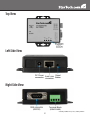
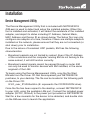
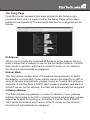
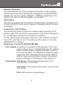
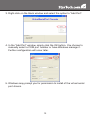
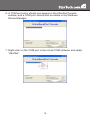
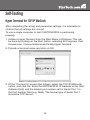
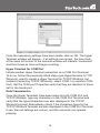
NETRS2321E
NETRS2321EEU
NETRS2321EGB
Instruction Manual
Serial Over IP Ethernet
Device Server
1 Port RS-232/422/485 Serial
over IP Ethernet Device Server
Manual Revision:10/13/2010
For the most up-to-date information, please visit www.startech.com
FCC Compliance Statement
This equipment has been tested and found to comply with the limits for a Class B digital
device, pursuant to part 15 of the FCC Rules. These limits are designed to provide
reasonable protection against harmful interference in a residential installation. This
equipment generates, uses and can radiate radio frequency energy and, if not installed
and used in accordance with the instructions, may cause harmful interference to radio
communications. However, there is no guarantee that interference will not occur in a
particular installation. If this equipment does cause harmful interference to radio or
television reception, which can be determined by turning the equipment off and on, the
user is encouraged to try to correct the interference by one or more of the following
measures:
• Reorient or relocate the receiving antenna.
• Increase the separation between the equipment and receiver.
• Connect the equipment into an outlet on a circuit different from that to which the receiver
is connected.
• Consult the dealer or an experienced radio/TV technician for help.
Use of Trademarks, Registered Trademarks, and other Protected Names and Symbols
This manual may make reference to trademarks, registered trademarks, and other
protected names and/or symbols of third-party companies not related in any way to
StarTech.com. Where they occur these references are for illustrative purposes only
and do not represent an endorsement of a product or service by StarTech.com, or an
endorsement of the product(s) to which this manual applies by the third-party company
in question. Regardless of any direct acknowledgement elsewhere in the body of
this document, StarTech.com hereby acknowledges that all trademarks, registered
trademarks, service marks, and other protected names and/or symbols contained in this
manual and related documents are the property of their respective holders.
Table of Contents
Introduction...................................................................... 1
Packaging Contents.....................................................................1
System Requirements..................................................................1
Top View.......................................................................................2
Left Side View...............................................................................2
Right Side View............................................................................2
LED Indicators..............................................................................3
Wiring Architecture.......................................................................3
Installation........................................................................ 4
Device Management Utility...........................................................4
Web Console Configuration..........................................................6
Controller Update.........................................................................11
Virtual COM Port..........................................................................11
Factory Default Setting.................................................................14
Self-Testing...................................................................... 15
Hyper Terminal for TCP/IP WinSock.............................................15
Troubleshooting............................................................... 17
Specifications................................................................... 18
Technical Support............................................................ 19
Warranty Information....................................................... 19
i
Introduction
The StarTech.com RS-232/422/485 Serial Over IP Adapter is the
ideal solution for remotely controlling serial devices across a TCP/
IP network. Featuring a user-friendly, browser-based configuration of
network settings, serial port line settings, UART transmit/receive buffer
trigger levels and serial port flow control.
The serial over IP adapter also offers remote Telnet configuration and
support for IP, HTTP, ICMP and TCP network protocols, while providing
data transfer rates of up to 115.2Kbps per port.
Packaging Contents
• 1 x NETRS2321E / GB / EU adapter
• 1 x Power Adapter
• 1 x Instruction Manual
• 1 x Software CD
System Requirements
• 10/100 Mbps compatible TCP/IP Ethernet network
• Available power outlet at adapter location
• Virtual COM software: Microsoft® Windows® XP (32/64-bit)/Vista
(32-bit)/7 (32-bit)
1
Top View
Left Side View
Right Side View
*actual product may vary from photos
2
LED Indicators
• PWR (Green) - Power indicator
• Data (Red) - Data sent and received indicator
• 10/100 (Green) - Network signal indicator. When illuminated,
network connection is present.
• LED (Red) - Device status indicator. When operating under normal
status, this LED will blink once per second.
Wiring Architecture
3
Installation
Device Management Utility
The Device Management Utility that is included with NETRS2321E
(EM.exe) is used to detect and setup the installed adapter. When this
tool is installed and activated, it will detect the existence of the installed
adapter, and depict its status including IP Address, Subnet Mask,
MAC Address and Device ID as shown below. The Setup Tool can only
configure one adapter at a time, therefore if there are multiple adapters
installed on the network, please ensure that they are not connected (or
shut down) prior to installation.
Due to the nature of broadcast UDP packets, EM has the following
characteristics:
• Broadcast packets are not limited by subnet. Even if the IP Address
of the converters and the computer running EM do not belong to the
same subnet, it will still function correctly.
• Broadcast packet signals cannot be passed through a router. EM
can only be used to monitor devices with EM installed, in the same
segment of the LAN.
To begin using the Device Management Utility, copy the file titled
EM.exe from the Driver CD that accompanied your NETRS2321E
purchase, to your desktop. The file can be located in the following path
on the Driver CD:
E:\IO_over_IP\Utilities\Em (E: represents the CD/DVD-ROM drive)
Once the file has been copied to the desktop, connect NETRS2321E
to your LAN, using the available LAN port. Connect the included power
adapter (9V DC, 500mA) to the power port provided on NETRS2321E.
Wait for a few moments for the device to be detected, and double click
on the EM.exe icon to launch the application:
4
To refresh the status of the adapter network connection, click on View,
then Refresh. This should be performed following any configuration
changes.
To configure the IP Address assigned to NETRS2321E, click on
Config, then IP Address. Assign an IP Address with the same Subnet
Mask of your computer, ensuring that the address that is assigned is
not already in use on the network. When you press the OK button, the
IP Address will be refreshed within 2-3 seconds.
5
NOTE: Because the Device Management Utility uses broadcast UDP
packets, configuration is only allowed when the device’s password is
left empty.
Web Console Configuration
In addition to basic IP Address and subnet mask, specific device
settings can be set using an Internet browser, such as Internet
Explorer or Netscape etc.
If the IP Address of the adapter is already known (default is
192.168.0.10), enter it into the browser address line to launch the
Login Page.
The Login Page
Once the Login Page has been launched (as shown on page 6), the
following will be displayed:
System time elapsed
The time elapsed since the adapter was connected to the LAN will be
displayed here.
Firmware version
The installed firmware will be identified here by date code.
Serial number
The adapter serial number consists of five digits and a unique MAC
address used by the network in hexadecimal format.
Password (Setup login)
This field allows you to enter the administration password for
authentication. By default, the password is left empty. If you have
changed the password to something other than the default, press and
hold the Reset button (located next to the RJ45 port) for five seconds.
The adapter will power cycle; once it has been re-detected on the
network, the password will have been reset to default. Please note that
if there are more than three consecutive incorrect password attempts,
the login function will be disabled for 15 minutes. During this period,
even if the correct password is supplied, the login will not proceed
6
The Setup Page
Once the correct password has been entered in the Setup Login
password field, click on Login to enter the Setup Page, which offers
advanced configurability. The elements that can be configured are as
follows:
IP Address
Allows you to modify the assigned IP Address of the adapter. Do not
enter a value that is already in use on the connected network. If DHCP
client mode is enabled, and there is a DHCP server on the network,
this field will automatically be assigned.
Subnet Mask
This field allows configuration of the subnet mask address, to which
the adapter is connected. If your subnet mask is provided by an ISP or
internal network administrator, please inquire as to what this setting is,
and enter it into this field. If DHCP client mode is enabled, and there is
a DHCP server on the network, this field will automatically be assigned.
Gateway address
This field contains the gateway or router IP address. If your gateway
address is provided by an ISP or internal network administrator, please
inquire as to what this setting is, and enter it into this field. If DHCP
client mode is enabled, and there is a DHCP server on the network,
this field will automatically be assigned.
7
Network link speed
This field indicates the Ethernet physical link speed. “Auto” indicates
that the speed has automatically been assigned by the NETRS2321E
adapter. You can also specify 10Mbps or 100Mbps, depending on the
speed of the hub to which the adapter is connected.
DHCP client
This field will indicate either enabled or disabled status. Enable DHCP
if there is a DHCP server on your network, otherwise, leave this value
as disabled.
Socket Port of HTTP Setup
The socket port used to conduct the browser setup. Normally, HTTP
protocol uses TCP port 80 for communication. If the field is changed to
81, port 80 will be reserved as an Internet connection.
To enter the browser setup page, “http://x.x.x.x:81” should be entered
for port 81, and “http://x.x.x.x” for socket port 80, where x.x.x.x is the
NETRS2321E IP address.
Socket port of serial I/O (RS-232/422/485):
•Port number: A socket port assigned to the serial port. This 16-bit
number ranges from 1 to 65535. Because the numbers
below 1000 are used for specific purposes (i.e. 80 is
for the http protocol), it is advisable to select a number
larger than 1000. Generally, the port number 4660 is
used for serial communication. However, you should
specify a different port number for each serial port.
•Socket type: TCP Server: TCP protocol, passive open, to be
connected from TCP clients.
TCP Client: TCP protocol, active open, connect to the
TCP Server.
UDP: UDP protocol, connectionless.
8
Destination setting:
•Destination IP Address: The server IP Address and socket port
would be connected in TCP client and
UDP client mode for a certain server IP
Address.
•Destination socket port: The server socket port would be
connected in TCP Client and UDP Client
mode for a certain serial port.
•Connection: The connection can be selected in two modes, Auto or
Manual.
•Serial I/O setting: Baud rate, parity, data bits, stop bits
Baud rate: 300 - 115200bps
Parity: None, Even, Odd
Data Bits: 7,8
Stop Bit: 1 or 2
•Serial I/O Interface: RS-232: TxD, RxD for data stream, no flow
control
RS-232 (RTS/CTS): TxD, RxD for data stream,
RTS/CTS for flow control
RS-232 (RTS/CTS, DTR/DSR): TxD, RxD for
data stream, RTS/CTS for flow control. DTR
for socket status, DSR for socket open/close
control
RS-485 (Half duplex): Half duplex RS-485
interface
RS-422 (Full duplex): Full duplex RS-422
interface
•Packet mode of serial input: Packet mode could be in enabled/
disabled mode. If packet mode is enabled,
the data input from UART will be deferred
until the input buffer is full, or NETRS2321E
9
detects a 10-character packet gap and no
more characters have arrived. The block
waiting time is extended, to avoid splitting
the complete packet.
•Device ID: User assigned ID number for NETRS2321E. Available ID
range includes 0-65535
•Report device ID when connected: In TCP mode, if this parameter
is enabled, every time the socket is connected,
NETRS2321E will immediately report its
device ID in the following formats:
Serial #1 - nnnnnA[LF][CR]
Serial #2 - nnnnnB[LF][CR]
Digital I/O - nnnnnC[LF][CR]
The total length is 8 bytes, where “nnnnn” is a
5-digit device ID, assigned by the user; [LF] is
decimal 10; [CR] is decimal 13.
•Setup password:Administration password used to login to the
Controller Setup page. It may be left as empty, or
up to 15 characters long.
•Access password: During socket connection, the Access/
Authentication password may be empty or
up to entered as 15 characters long. If the
Access password is left empty, authentication
is disabled. Otherwise, the authentication will
proceed as normal. If authentication fails, or no
password is supplied within 10 seconds, the
socket will be closed.
10
Controller Update
Once you have entered the necessary parameters, press the Update
button. NETRS2321E will save all parameters in internal non-volatile
memory and then reboot. It will take roughly 5 or 10 seconds to
complete the whole process following which a new login page will be
presented, indicating that the Controller has been updated and that
NETRS2321E is restarting.
You can re-login and check if all parameters have been correctly saved.
Once you have confirmed accuracy, you can close the browser.
NOTE: If the domain under which NETRS2321E is operating is
different from that of the computer running the browser, the login page
won’t appear unless the NETRS2321E Gateway Address has correctly
been set.
Virtual COM Port
The virtual COM port software, VSerPortConsole, is used to map
a NETRS2321E unit on the network, to a COM port on the local
computer system. The computer will treat the COM port as a regular
serial port that is directly on the computer system. To use the virtual
COM port feature:
1.Ensure that the NETRS2321E unit has already been configured
properly, and is accessible on the network.
2.Copy the virtual COM port software onto the computer’s hard drive
from the CD, if not already and run the software. Make sure to only
run the version appropriate for your operating system.
NOTE: The latest version of the virtual COM port software can be
downloaded from www.startech.com
11
3.Right-click on the blank window and select the option to “Add Port”.
4.In the “Add Port” window, simply click the OK button. You choose to
manually select a COM port number or have Windows manage it.
Further configuration will occur later.
5.Windows may prompt you for permission to install of the virtual serial
port drivers.
12
6.A COM port entry should now appear in the VSerPortConsole
window, and a COM port should also be visible in the Windows
Device Manager.
7.Right-click on the COM port in the virtual COM software and select
“Add Net”.
13
8.The “Add Net” window will allow you to configure the COM port to
the settings used by the NETRS2321E unit you wish to associate
with. Select the proper operating mode, network settings used
to configure the NETRS2321E unit previously (see Web Console
Configuration).
Factory Default Setting
If you forget the setup password, or have incorrect settings making the
converter inoperable, reset the settings to factory default:
You can remove power from NETRS2321E and use any point tip to
push the Reset button (next to the RJ45 port) and hold it for 5 seconds.
This will automatically turn NETRS2321E back on, and reset the
password to default.
14
Self-Testing
Hyper Terminal for TCP/IP WinSock
After completing the wiring and parameter settings, it is advisable to
confirm that all settings are correct.
To use a single computer to test if NETRS2321E is performing
properly:
1.Initiate a Hyper Terminal from the Start Menu in Windows. This can
be done by clicking on the Start button, selecting All Programs, then
Accessories, Communications and finally Hyper Terminal.
2.Provide a terminal name and click on OK.
3.At the “Connect to” screen that follows, select the TCP/IP(Winsock)
option, and click OK. Enter the NETRS2321E IP Address in the Host
Address Field, and the Socket port number set for Serial Port 1 in
the Port number field (e.g. 4660). The Socket type of Serial Port 1
should be TCP Server:
15
Once the necessary settings have been made, click on OK. The Hyper
Terminal window will appear - if all settings are correct, the time clock
at the lower left corner of the terminal window will indicate “connected”
and the hh:mm:ss timer will begin counting.
Hyper Terminal for COM Port
Initiate another Hyper Terminal connection as a COM Port Terminal.
To do so, follow the previously listed steps (see HyperTerminal for TCP
Winsock), used to create a Hyper Terminal for TCP/IP WinSock, but
instead of selecting TCP/IP (Winsock), select COM 1 (or another COM
Port). Set the COM port Properties such that they are identical to those
set for the Serial port.
Data Transmission
Once the Hyper Terminals have been setup for both COM Port and
TCP/IP Winsock, type any characters in the COM Port Terminal and
verify that the typed characters are also displayed in the TCP/IP
Winsock terminal. Alternatively, check if the characters typed in the
TCP/IP WinSock Terminal are also displayed in the COM Port Terminal.
If yes, then all settings are correct, and the converter can operate
properly.
16
Troubleshooting
If the Device Management Utility (EM.exe) doesn’t detect the
converter on the network:
Please verify:
• The power is properly connected to NETRS2321E
• The network cable is properly connected between NETRS2321E
and the hub
• There is no firewall interference. If the computer you are using
is Windows XP, the Windows Firewall function may be enabled,
which will block the Device Management Utility from detecting the
NETRS2321E IP Address. Therefore, you may temporarily disable
the Windows Firewall function, and re-enable it once the necessary
parameters have been configured.
If you cannot setup the NETRS2321E using Internet Explorer:
Please verify that the network domain of the PC is the same as the
converter.
17
Specifications
1 x DB9 male
1 x 4-wire Terminal Block
Connectors
1 x RJ45 Ethernet female
1 x DC Power
LEDs
Power, Data, LAN Link, System
Supported Serial Protocol
RS232/422/485
Ethernet Link Speed
10/100 Mbps
Maximum Data Transfer Rate
115.2 Kbps
Power Adapter
9VDC, 500mA, type M plug
Operating Temperature
0°C ~ 60°C (32°F ~ 140°F)
Storage Temperature
-10°C ~ 70°C (14°F ~ 158°F)
Humidity
0 ~ 80% RH
Dimensions
90.0mm x 90.0mm x 26.0mm
Weight
105 g
18
Technical Support
StarTech.com’s lifetime technical support is an integral part of our
commitment to provide industry-leading solutions. If you ever need
help with your product, visit www.startech.com/support and access our
comprehensive selection of online tools, documentation, and downloads.
Warranty Information
This product is backed by a one year warranty.
In addition, StarTech.com warrants its products against defects in
materials and workmanship for the periods noted, following the initial
date of purchase. During this period, the products may be returned
for repair, or replacement with equivalent products at our discretion.
The warranty covers parts and labor costs only. StarTech.com does
not warrant its products from defects or damages arising from misuse,
abuse, alteration, or normal wear and tear.
Limitation of Liability
In no event shall the liability of StarTech.com Ltd. and StarTech.com USA
LLP (or their officers, directors, employees or agents) for any damages
(whether direct or indirect, special, punitive, incidental, consequential, or
otherwise), loss of profits, loss of business, or any pecuniary loss, arising
out of or related to the use of the product exceed the actual price paid
for the product. Some states do not allow the exclusion or limitation of
incidental or consequential damages. If such laws apply, the limitations
or exclusions contained in this statement may not apply to you.
19
StarTech.com has been making “hard-to-find easy” since 1985,
providing high quality solutions to a diverse IT and A/V customer
base that spans many channels, including government, education
and industrial facilities to name just a few. We offer an unmatched
selection of computer parts, cables, A/V products, KVM and Server
Management solutions, serving a worldwide market through our
locations in the United States, Canada, the United Kingdom and
Taiwan.
Visit www.startech.com today for complete information about all
our products and to access exclusive interactive tools such as the
Cable Finder, Parts Finder and the KVM Reference Guide.