1
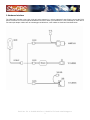
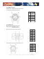
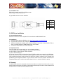
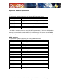
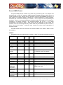
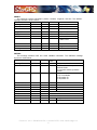
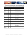
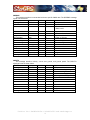
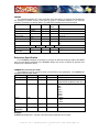
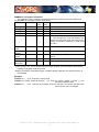
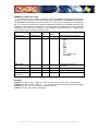
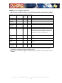
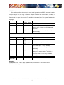
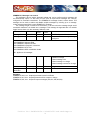
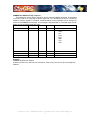
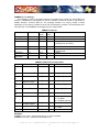
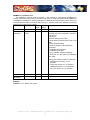
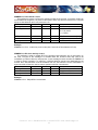
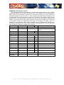
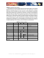
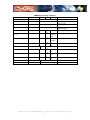
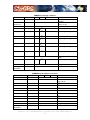
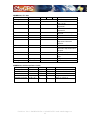
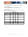
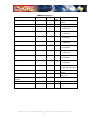
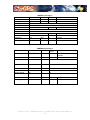
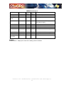
?
Ultra Low Power, High Sensitivity
GPS-NX01 Receiver
User Guide
PixSoft Inc. Tel: +1.204.885.4936 Fax: +1.204.895.4173 E-mail: [email protected]
1
?
1. Introduction
1.1 Overview
The GPS-NX01 Smart Receiver is an ultra low power GPS receiver based on the proven technology of the
NemeriX NJ1030A chipset. The positioning application meets strict needs such as car navigation, mapping,
surveying, security, agriculture and so on. Only a clear view of the sky and a power supply are needed. With its
ultra low power consumption, the smart receiver tracks up to 16 satellites at a time, re-acquires satellite signals in
1 second (average) and updates position data every second.
The GPS-NX01 can be used as a general purpose GPS receiver with NMEA-0183 output. However, its most
unique feature is the ability to transfer GPS data (time, date, latitude and longitude) to a wide variety of telescopes
that understand the Meade LX200 Command Set or Celestron NexStar Communication Protocol.
1.2 Features
The GPS-NX01 provides a host of features that make it easy to use:
? Fast time-to-first-fix and ultra low power consumption
? High performance NemeriX chipset tracks up to 16 satellites in parallel
? Compact design with integrated antenna/receiver
? Rechargeable Lithium cell sustains internal clock and memory (recharges during normal operation)
? One full duplex serial port with selectable baud rates and NMEA messages
? Supports standard NMEA-0183, Meade LX200 and Celestron NexStar communication protocols
? Automatically detects telescope type (Meade, Celestron or none)
? Switches to standard NMEA output after 30 seconds if no telescope is detected
? LED power indicator blinks to indicate receiver status
? Switches to sleep mode (LED off) 20 minutes after the telescope accepts GPS data
? Automatic cold start with no user initialization required
1.3 Specifications
The GPS-NX01 technical specifications are listed below:
? Size: 47 x 39 x 16 mm (1.9" x 1.5" x 0.6")
? Weight: 70 g (2.5 oz)
? Tracks up to 16 satellites (-152 dBm sensitivity)
? Warm start in 38 seconds (50%), cold start in 45 seconds (50%)
? Position accuracy: 3 meters CEP (50%), 7m (90%)
? Velocity: 0.1 meters/second, without SA
? Time: +/- 100 nanosecond synchronized to GPS time
? Altitude: 18,000 meters (60,000 feet) max
? Velocity: 515 meters / second (1000 knots) max
? Acceleration: 4 G, max
? Interface: RS-232 with 2 m (78") cable (PS/2 Female)
? Baud rate: 9600 (default), 4800, 19200, 38400
? NMEA-0183 Version 2.2 ASCII output: GPGGA, GPGSA, GPGSV, GPRMC, GPVTG, GPGLL, GPZDA
? Meade LX200 Command Set
? Celestron NexStar Communication Protocol (requires firmware version 2.3, 104.0 or 4.0+)
? Power: 3.6 to 5.5 V @ 35 ma (normal) or 16 ma (sleep mode)
? Backup power: 3V rechargeable lithium cell (350 hours)
? Operating temperature: -40 to +85°C (-40 to +185°F)
? Relative humidity: 5% to 90% non-condensing
PixSoft Inc. Tel: +1.204.885.4936 Fax: +1.204.895.4173 E-mail: [email protected]
2
?
2. Hardware Interface
The GPS-NX01 includes a low noise, high gain active antenna in a unique waterproof case. Simply connect the PS/2
female connector to one of the optional accessories and link to either your notebook PC, PDA, telescope or other device.
For telescope adapter cables refer to www.stargps.ca/cables.htm, other cables are listed and described below:
PixSoft Inc. Tel: +1.204.885.4936 Fax: +1.204.895.4173 E-mail: [email protected]
3
?
2.1 GPS-NX01 Connector
Standard cable: 2 meters with female PS/2 connector.
Pin Assignment of standard PS/2 Din Jack
Pin
1
2
3
4
5
6
Signal
Tx
(RS-232)
+5VDC
Tx (TTL)
GND
Rx (TTL)
Rx
(RS-232)
2.2 GPS-DB9 Cable
Mini Din Female and PS/2 male connector:
Cable Length: To GPS-NX01: 1 meter
RS-232 to PS/2: 45 cm
Mini Din Female connector function definition:
Pin Signal
1
N.C.
2
TX
3
RX
4
N.C.
5
GND
6
N.C.
7
N.C.
8
N.C.
9
N.C.
PS/2 composite connector function definition (to PC):
Pin Signal
1 +5VDC
2
N.C.
3
N.C.
4
GND
5
N.C.
6
N.C.
PixSoft Inc. Tel: +1.204.885.4936 Fax: +1.204.895.4173 E-mail: [email protected]
4
?
2.3 GPS-USB Cable
PS/2 male connector and A Type USB connector:
Cable Length: USB to PS/2: 50 cm
A Type USB connector function definition:
Pin Signal
1 +5VDC
2
D+
3
D4
GND
3. USB Driver Installation
3.1 System Requirements
Pentium or above and other compatible PC with Windows 98/ME/2000/XP /Vista
3.2
1.
2.
3.
Installation
Download and install the USB driver from http://www.stargps.ca/pub/pl2303.zip
Plug the USB connector into a USB port on the computer.
After the installation is complete, go to <Device Manager> and select <Ports (COM & LPT)> to
verify if a virtual COM port <USB to Serial Port> was created.
4. Connect the GPS-NX01 to the GPS-USB cable.
3.3 Important Notice
Verify the COM port # to start using your own navigating software.
1. Click <Start> menu, select <Settings>, then enter <Control Panel>
2. After entering <Control Panel>, select <System>
3. Select <Device Manager>
4. Find the <Connect Port> and check the Virtual COM Port, which was created by the USB driver.
Please note that the Virtual COM Port number might be different from every computer. Before
using navigating software, please confirm the COM Port numbers created by your computer and
provided by your navigation software. They must be the same Com Port numbers. Otherwise, the
navigating software won’t receive the satellite signal for the un-matched COM Port setting.
4. Warranty
The GPS-NX01 receiver is warranted to be free from defects in material and functions for one year
from the date of purchase. Any failure of this product within this period under normal conditions will
be replaced at no charge (excluding shipping costs).
PixSoft Inc. Tel: +1.204.885.4936 Fax: +1.204.895.4173 E-mail: [email protected]
5
?
Appendix : Software Specification
NMEA Protocol
The software is capable of supporting the following NMEA message formats:
NMEA Message Prefix Format
Direction
$GPGGA(1)*
GPS fix data.
Out
$GPGLL(0)
Geographic position Latitude / Longitude.
Out
$GPGSA(3)*
GNSS DOP and actives satellites
Out
$GPGSV(3)*
Satellites in view.
Out
$GPRMC(1)*
Recommended minimum specific GNSS data. Out
$GPVTG(1)*
Velocity and track over ground.
Out
$GPZDA (0)
Date and time.
Out
* The GPS will operate in telescope mode if all NMEA messages are off (this is the default setting).
In this mode the GPS attempts to determine the telescope protocol (Meade or Celestron). If no
telescope is found after 30 seconds the GPS LED will blink rapidly for 5 seconds and then NMEA
output will begin as shown in the above table (0=none, 1=every second, 3=every three seconds).
NMEA Extensions
The software is capable of supporting the following NMEA extensions:
NMEA Message Prefix Format
$PNMRX100
Set serial port parameters.
$PNMRX101
Navigation initialization
$PNMRX103
NMEA message rate control
$PNMRX104
LLA navigation initialization
$PNMRX106
Set Datum.
$PNMRX107
NemeriX messages rate control
$PNMRX108
NMEA message sequence control
$PNMRX110
Fix Settings
$PNMRX111
Software Reset
$PNMRX112
Operating Mode Control
$PNMRX113
Fix and Extraction control
$PNMRX300
Almanac data transfer
$PNMRX301
Ephemeris data transfer.
$PNMRX302
Ionospheric correction
$PNMRX303
UTC Time
$PNMRX304
GPS Constellation Health Status
$PNMRX600
SW Version report
$PNMRX601
ISP mode
$PNMRX603
Settings Report
Direction
In
In
In
In
In
In
In
In
In
In
In
In / Out
Out
Out
Out
Out
Out
In
Out
PixSoft Inc. Tel: +1.204.885.4936 Fax: +1.204.895.4173 E-mail: [email protected]
6
?
General NMEA Format
The general NMEA format consists of an ASCII string commencing with a ‘$’ character and
terminating with a <CR><LF> sequence. NMEA standard messages commence with ‘GP’ then a
3-letter message identifier. NemeriX specific messages commence with $PNMRX followed by a 3
digit number. The message header is followed by a comma delimited list of fields optionally
terminated with a checksum consisting of an asterix ‘*’ and a 2 digit hex value representing the
checksum. There is no comma preceding the checksum field. When present, the checksum is
calculated as a bytewise exclusive of the characters between the ‘$’ and ‘*’. As an ASCII
representation, the number of digits in each number will vary depending on the number and
precision, hence the record length will vary. Certain fields may be omitted if they are not used, in
which case the field position is reserved using commas to ensure correct interpretation of
subsequent fields.
The tables below indicate the maximum and minimum widths of the fields to allow for buffer
size allocation.
$GPGGA
This message transfers global positioning system fix data. The $GPGGA message structure is
shown below:
Field
Format
Min
Max
Notes
chars
chars
Message ID
$GPGGA
6
6
GGA protocol header.
UTC Time
hhmmss.sss 2,2,2.3
2,2,2.3
Fix time to 1ms accuracy.
Latitude
float
3,2.4
3,2.4
Degrees * 100 + minutes.
N/S Indicator
char
1
1
N=north or S=south
Longitude
float
3,2.4
3,2.4
Degree * 100 + minutes.
E/W
Char
1
1
E=east or W=west
indicator
Position Fix
Indictor
Int
1
1
0: Fix not available or invalid.
1: GPS SPS mode. Fix available.
Satellites
Used
Int
2
2
Number of satellites used to calculate fix.
HDOP
MSL Altitude
Units
Geoid
Separation
Units
Age of
Differential
Corrections
Diff
Reference
Corrections
Checksum
Message
terminator
Float
Float
Char
Int
1.1
1.1
1
(0) 1
3.1
5.1
1
4
Horizontal Dilution of Precision.
Altitude above mean seal level
M Stands for “meters”.
Separation from Geoid, can be blank.
Char
int
1
(0) 1
1
5
M Stands for “meters”.
Age in seconds Blank (Null) fields when
DGPS is not used.
int
4
4
0000.
*xx
<CR> <LF>
(0) 3
2
3
2
2 digits.
ASCII 13, ASCII 10.
PixSoft Inc. Tel: +1.204.885.4936 Fax: +1.204.895.4173 E-mail: [email protected]
7
?
$GPGLL
This message transfers Geographic position, Latitude, Longitude, and time. The $GPGLL
message structure is shown below:
Field
Format
Min chars Max chars Notes
Message ID
$GPGLL
6
6
GLL protocol header.
Latitude
Float
1,2.1
3,2.4
Degree * 100 + minutes.
N/S Indicator
Char
1
1
N=north or S=south.
Longitude
Float
1,2.1
3,2.4
Degree * 100 + minutes.
E/W indicator
Character
1
1
E=east or W=west.
UTC Time
hhmmss.sss 1,2,2.1
2,2,2.3
Fix time to 1ms accuracy.
Status
Char
1
1
A Data Valid.
V Data invalid.
Mode Indicator
Checksum
Message terminator
Char
*xx
<CR><LF>
1
(0) 3
2
1
3
2
A Autonomous
2 digits.
ASCII 13, ASCII 10.
$GPGSA
This message transfers DOP and active satellites information. The $GPGSA message
structure is shown below:
Field
Format
Min chars Max
Notes
chars
Message ID
$GPGSA
6
6
GSA protocol header.
Mode
Char
1
1
M Manual, forced to operate in
selected mode.
A Automatic switching between
modes.
Mode
Int
1
1
1 Fix not available.
2 2D position fix.
3 3D position fix.
Satellites Used
Satellites Used
…
Satellites Used
PDOP
HDOP
VDOP
Checksum
Message terminator
Int
Int
.
Int
Float
Float
Float
*xx
<CR> <LF>
2
2
..
2
1.1
1.1
1.1
0
2
2
2
..
2
3.1
3.1
3.1
3
2
SV on channel 1.
SV on channel 2.
..
SV on channel 12.
2 digits
ASCII 13, ASCII 10
PixSoft Inc. Tel: +1.204.885.4936 Fax: +1.204.895.4173 E-mail: [email protected]
8
?
$GPGSV
This message transfers information about satellites in view. The $GPGSV message structure
is shown below. Each record contains the information for up to 4 channels, allowing up to 12
satellites in view. In the final record of the sequence the unused channel fields are left blank with
commas to indicate that a field has been omitted.
Field
Format
Min
Max
Notes
chars
chars
Message ID
$GPGSV
6
6
GSA protocol header.
Number of
Int
1
1
Number of messages in the message
messages
sequence from 1 to 3.
Message
number
Int
1
1
Sequence number of this message in
current sequence, form 1 to 3.
Satellites in view
Satellite Id
Elevation
Azimuth
SNR
Int
Int
Int
Int
Int
1
2
1
1
(0) 1
2
2
3
3
2
Number of satellites currently in view.
Satellite vehicle 1.
Elevation of satellite in degrees.
Azimuth of satellite in degrees.
Signal to noise ration in dBHz, null if the sv
is not in tracking.
Satellite Id
Elevation
Azimuth
SNR
Int
Int
Int
Int
2
1
1
(0) 1
2
3
3
2
Satellite vehicle 2.
Elevation of satellite in degrees.
Azimuth of satellite in degrees.
Signal to noise ration in dBHz, null if the sv
is not in tracking.
Satellite Id
Elevation
Azimuth
SNR
Int
Int
Int
Int
2
1
1
(0) 1
2
3
3
2
Satellite vehicle 3.
Elevation of satellite in degrees.
Azimuth of satellite in degrees.
Signal to noise ration in dBHz, null if the sv
is not in tracking.
Satellite Id
Elevation
Azimuth
SNR
Int
Int
Int
Int
2
1
1
(0) 1
2
3
3
2
Satellite vehicle 4.
Elevation of satellite in degrees.
Azimuth of satellite in degrees.
Signal to noise ration in dBHz, null if the sv
is not in tracking.
Checksum
Message
terminator
*xx
<CR>
<LF>
(0) 3
2
3
2
2 digits.
ASCII 13, ASCII 10.
PixSoft Inc. Tel: +1.204.885.4936 Fax: +1.204.895.4173 E-mail: [email protected]
9
?
$GPRMC
This message transfers recommended minimum specific GNSS data. The $GPRMC message
format is shown below.
Field
Format
Min chars Max chars Notes
Message ID
$GPRMC
6
6
RMC protocol header.
UTC Time
hhmmss.sss 1,2,2.1
2,2,2.3
Fix time to 1ms accuracy.
Status
char
1
1
A Data Valid.
V Data invalid.
Latitude
N/S Indicator
Longitude
E/W indicator
Speed over ground
Course over ground
Date
Magnetic variation
E/W indicator
Mode
Checksum
Message terminator
Float
Char
Float
Char
Float
Float
ddmmyy
Blank
Blank
Char
*xx
<CR> <LF>
1,2.1
1
1,2.1
1
1,1
1.1
2,2,2
(0)
(0)
1
(0) 3
2
3,2.4
1
3,2.4
1
5.3
3.2
2,2,2
(0)
(0)
1
3
2
Degrees * 100 + minutes.
N=north or S=south.
Degrees * 100 + minutes.
E=east or W=west.
Speed over ground in knots.
Course over ground in degrees.
Current date.
Not used.
Not used.
A Autonomous
2 digits.
ASCII 13, ASCII 10.
$GPVTG
This message transfers Velocity, course over ground, and ground speed. The $GPVTG
message format is shown below.
Field
Format
Min chars Max chars Notes
Message ID
$GPVTG
6
6
VTG protocol header.
Course (true)
Float
1.1
3.2
Measured heading in degrees.
Reference
Char
1
1
T = true heading.
Course (magnetic)
Float
1.1
3.2
Measured heading (blank).
Reference
Char
1
1
M = magnetic heading.
Speed
Float
1.1
4.2
Speed in knots.
Units
Char
1
1
N = knots.
Speed
Float
1.1
4.2
Speed
units
Char
1
1
K = Km/h.
Mode
Char
1
1
A Autonomous
Checksum
*xx
(0) 3
3
2 digits.
Message terminator <CR> <LF> 2
2
ASCII 13, ASCII 10.
PixSoft Inc. Tel: +1.204.885.4936 Fax: +1.204.895.4173 E-mail: [email protected]
10
?
$GPZDA
This message transfers UTC Time and Date. Since the latency of preparing and transferring
the message is variable, and the time does not refer to a particular position fix, the seconds
precision is reduced to 2 decimal places. The $GPZGA message format is shown below.
Field
Format
Min chars Max
Notes
chars
Message ID
$GPZDA
6
6
ZDA protocol header.
hhmmss
UTC time
2,2,2.2
2,2,2.2
00000000.00 to 235959.99
.ss
UTC day
dd
2
2
01 to 31, day of month.
UTC month
mm
2
2
01 to 12.
UTC Year
Local zone hours
yyyy
4
(-)2
4
(-)2
1989-9999.
Offset of local time zone (-13) to
13.
Local zone minutes
Checksum
Message
terminator
Unsigned
2
*xx
(0) 3
<CR> <LF> 2
Int
2
3
2
2 digits.
ASCII 13, ASCII 10.
Extensions Specification
For all $PNMRX messages it is possible to configure an alternative string to replace the NMRX
part, the node always responds to the $PNMRX strings and can be configured to generate and
respond to the alternative string.
$PNMRX100, Set serial port mode
This message is sent to control the serial
message format is shown below.
Field
Format
Min chars
Message ID
$PNMRX100 6
Protocol
Char
1
communications port parameters. The $PNMRX100
Max chars
6
1
Baud
Int
4
6
Parity
Char
1
1
Checksum
*xx
(0) 3
3
Notes
PNMRX100 protocol header.
0 NMEA mode
1 NemeriX Binary Mode (under dev)
1200.
2400.
4800.
9600.
19200.
38400.
57600.
0. None.
1. Odd.
2. Even.
2 digits.
Message
terminator
<CR> <LF>
2
2
ASCII 13, ASCII 10.
Example:
$PNMRX100,0,4800,0*xx : sets the UART baud rate to 4800 bps and no parity.
PixSoft Inc. Tel: +1.204.885.4936 Fax: +1.204.895.4173 E-mail: [email protected]
11
?
$PNMRX101, Navigation Initialization
This message is sent to initialize navigation parameters to speed up initial acquisition time.
The $PNMRX101 message format is shown below.
Field
Format
Min
Max
Notes
chars
chars
Message ID $PNMRX101 6
8
PNMRX101 protocol header.
ECEF_X
Int
(-)7
(-)7
Signed ECEF x co-ordinate in meters
ECEF_Y
Int
(-)7
(-)7
Signed ECEF y co-ordinate in meters
ECEF_Z
Int
(-)7
(-)7
Signed ECEF z co-ordinate in meters
Clock offset Int
(0) 1
6
Clock offset of GPS receiver, in [Hz x 100] wrt
L1. This changes the clock bias stored in the
settings not the actual clock bias used by the
system. A cold start is necessary, in order to use
this value.
Time of
week
Week
number
Channel
count
Checksum
Message
terminator
Int
1
6
Offset from start of week in seconds
Int
1
4
GPS week number
Int
1
2
*xx
<CR> <LF>
(0) 3
2
3
2
Maximum number of TM to be used. Min 12,
max 16.
2 digits.
ASCII 13, ASCII 10.
- If used, all three X,Y, and Z components of the ECEF position must be provided, otherwise the
message is declared invalid as a whole
- Modifying the ECEF coordinates triggers a software system reset after successful execution of
the message
Examples:
$PNMRX101,,,,,,,,8,*xx : Executes a factory reset
$PNMRX101,-742507,-5462738,3196706,,,,,,*xx: Sets the receiver position to ECEF (,,) and
executes a software reset
$PNMRX101,,,,,,,,4,*xx : Sets the fix procedure mode the cold start. This will be valid after each
reset, until this value is changed.
PixSoft Inc. Tel: +1.204.885.4936 Fax: +1.204.895.4173 E-mail: [email protected]
12
?
$PNMRX103, NMEA rate control
This message is sent to enable or pause the output of an NMEA message and to determine its
output rate. The sequence of the output sequence is determined by the $PNMRX107 message.
The $PNMRX103 message format is shown below. The rate of each message can individually be
set. If ‘0’ is used, the output of the message is skipped (according to the message sequence). The
message length is limited to 80 characters, in the event that the message length would exceed 80
characters it is divided into 2 messages. This message is supported also in a variable length
format, where only the necessary fields are used.
Field
Format
Min
Max
Notes
chars
chars
Message ID
$PNMRX103 8
8
PNMRX103 protocol header.
Mask ID
Int
3
3
Mask identifier: possibilities are
GGA
GLL
GSA
GSV
RMC
VTG
ZDA
ALL (applies to all
messages)
Mask value
Int
1
1
Mask ID
Checksum
Message
terminator
Int
*xx
<CR> <LF>
2
(0) 3
2
2
3
2
Output rate in seconds
(0=paused)
Mask identifier.
2 digits.
ASCII 13, ASCII 10.
Examples:
$PNMRX103, GSV, 2,GGA, 1,ZDA, 0*xx: GSV is output every 2s, GGA every 1s and no ZDA.
$PNMRX103, GSV, 2,GGA, 1,ZDA, 0,,,,,,,,,*xx : same as above, but using a fixed length message
$PNMRX103, ALL, 2*xx: all messages are output every 2s.
$PNMRX103, ALL, 0*xx: skips all messages.
PixSoft Inc. Tel: +1.204.885.4936 Fax: +1.204.895.4173 E-mail: [email protected]
13
?
$PNMRX104, LLA navigation initialization
This message enables the receiver to be initialized using LLA data to speed up satellite
acquisition. The first 4 values defining the position (if used) must be all present in the message.
Otherwise the whole massage is considered invalid.
Field
Format
Min
Max
Notes
chars
chars
Message ID
$PNMRX104 8
8
PNMRX104 protocol header. (under dev.)
Latitude
Float
1,2.1
3,2.4
Degrees * 100 + minutes. (under dev.)
N/S
Char
1
1
N=north or S=south. (under dev.)
Indicator
Latitude
Float
1,2.1
3,2.4
Degrees * 100 + minutes. (under dev.)
E/W
Char
1
1
E=east or W=west. (under dev.)
Indicator
Altitude
Int
(-) 1
(-) 6
Altitude above MSL, in meters.
Clock offset
Int
(0) 1
6
Clock offset of GPS receiver. This changes the
clock bias stored in the settings, not the actual
clock bias used by the system. A cold start is
necessary, in order to use this value.
Time of
week
Week
number
Channel
count
Checksum
Message
terminator
Int
1
6
Int
1
4
Int
1
2
*xx
<CR> <LF>
(0) 3
2
3
2
Offset from start of week in seconds. (under
dev.)
GPS week number.
Maximum number of TM to be used. Min12,
max 16.
2 digits.
ASCII 13, ASCII 10.
- If used, all five components (Lat, N/S, Long E/W, alt) of the LLA position must be provided,
otherwise the message is declared invalid as a whole
- Modifying the LLA coordinates triggers a software system reset after successful execution of the
message.
PixSoft Inc. Tel: +1.204.885.4936 Fax: +1.204.895.4173 E-mail: [email protected]
14
?
$PNMRX106, Datum
This message defines the conversion model used for mapping the ECEF coordinates into the
LLA ones. The default transformation uses WGS84 approximation. The transformation method
can be changed into one using a reference Ellipsoid combined with a local datum, to obtain a
specific estimation of the local earth geometry. Once the datum has been changed it will be
applied to all LLA data, including the LLA navigation initialization Data. This message enables the
receiver to be configured to use map datum from an internal table, or datum supplied as part of the
message.
Field
Format
Min
Max
Notes
chars
chars
Message ID
$PNMRX106 6
8
PNMRX106 protocol header.
Correction
Unsigned
1
1
If 1 apply EGM96 geoid correction (warning:
Mode
should be applied only when Map Datum is
equal to 216). If 0 there is no EGM96 geoid
correction.
Map Datum
Int
(0) 1
3
Reference number of the appropriate map
datum to apply.
(-)5
X offset in meters (-9999 to 9999)
(-)5
Y offset in meters (-9999 to 9999)
(-)5
Z offset in meters (-9999 to 9999)
8
Inverse flatness of reference geode. The value
to be used is (IFlat – 290) * 1000000).
The value must be in the range [6000000,
12000000]
Semi major axis of reference geode. The
values to be used is (MajorA – 6370000) *
1000).
The value must be in the range [6000000,
9000000]
2 digits.
ASCII 13, ASCII 10.
0-218 Map datum from internal table
500 User defined Datum
Dx
Int
Dy
Int
Dz
Int
Iflat
Int
(0)
(-)1
(0)
(-)1
(0)
(-)1
(0) 1
Majora
Int
(0) 1
8
Checksum
Message
terminator
*xx
<CR> <LF>
(0) 3
2
3
2
Examples:
$PNMRX106, 0,500, -2000,-2000,-2000,8257224,8137000*00*xx : User defined Datum
$PNMRX106, 1,216,,,,,*xx : WGS 84 Datum
PixSoft Inc. Tel: +1.204.885.4936 Fax: +1.204.895.4173 E-mail: [email protected]
15
?
$PNMRX107, Messages rate control
This message is sent to set the automatic update rate, and to configure which messages will
be automatically output, it is also sent from the node to report which messages are currently
configured for automatic transmission. The $PNMRX107 message format is shown below. This
message can be used to enable and disable multiple messages by including up to 4 message
codes and associated fields in each $PNMRX107 message.
The message length is limited to 80 characters, in the event that the message length would
exceed 80 characters it is divided into 2 messages. This message is supported also in a variable
length format, where only the necessary fields are used.
Field
Format
Min
Max
Notes
chars
chars
Message ID
$PNMRX107 8
8
PNMRX107 protocol header.
Message code
Char
3
3
Determines which message is being
configured.
300
301
302
303
304
PNMRX300 Almanac Data
PNMRX301 Ephemeris Data
PNMRX302 lonospheric corrections
PNMRX303 UTC Time
PNMRX304 GPS constellation health
ALL Applies to all messages
Mode
Int
1
1
0
1
2
3
Checksum
Message
terminator
*xx
<CR> <LF>
(0) 3
2
3
2
Disable message
Send message now
Send message on change
Send message now and on change
2 digits.
ASCII 13, ASCII 10.
Examples:
$PNMRX107,300,1*xx : Output the almanac stored in NVRAM
$PNMRX107,301,2*xx : Output Ephemeris will be output on change
$PNMRX107,ALL,2*xx : Output all output messages (300,301,302,303,304)
PixSoft Inc. Tel: +1.204.885.4936 Fax: +1.204.895.4173 E-mail: [email protected]
16
?
$PNMRX108, NMEA message sequence
This message is used to set the sequence used to output the NMEA messages. All messages
in the list are set to be output with a default output rate. The messages that are not included are
disabled. Once the sequence is defined, individual settings for the messages can be changed by
means of the $PNMRX103 message. This message is supported also in a variable length format,
where only the necessary fields are used.
Field
Format
Min chars Max chars Notes
Message ID
$PNMRX108 6
8
PNMRX108 protocol header.
Mask ID
Int
3
3
Mask identifier: possibilities are
GGA
GLL
GSA
GSV
RMC
VTG
ZDA
Mask ID
Checksum
Message terminator
Int
*xx
<CR> <LF>
3
(0) 3
2
3
3
2
Mask Identifier.
2 digits.
ASCII 13, ASCII 10.
Example:
$PNMRX108,GGA,GLL,GSA*xx :
Enables the GGA, GLL and GSA in this sequence, output every second. All other messages are
disabled
PixSoft Inc. Tel: +1.204.885.4936 Fax: +1.204.895.4173 E-mail: [email protected]
17
?
$PNMRX110, Fix Settings
This message is used to set various settings and masks which control how the software will
behave in relationship to the satellites in view, for example a mask can be set for the minimum
satellite elevation, minimum SNR etc. The message consists of a varying number of fields
depending on the number of masks to be set. Each mask setting consists if a mask identifier and
new value pair. The $PNMRX110 message format is shown below.
list
Notes
$PNMRX110
Int
Variant
PNMRX110 field
Min
Max
chars
chars
6
8
2
2
1
8
Mask ID
Value
Int
Variant
2
1
2
8
Checksum
Message
terminator
*xx
<CR> <LF>
(0) 3
2
3
2
Mask identifier.
New value for mask, dependent on the
preceding field.
2 digits.
ASCII 13, ASCII 10.
Field
Format
Message ID
Mask ID
Value
Mask Id
PNMRX110 protocol header.
Mask identifier, see below.
New value for mask, dependent on the
preceding field, see below.
PNMRX110 Mask Field interpretation
format
width units
Int: unsigned 2:2
Hours : Miuntes
mask
Local Time Zone
0
1
1
Maximum PDOP
Unsigned
4
x10, [0-100]
Maximum HDOP
Unsigned
4
x10, [0-100]
Maximum VDOP
Unsigned
4
x10, [0-100]
Minimum SNR
Unsigned
2
dB/Hz, [20-45]
Minimum Elevation
Unsigned
2
Degrees, [0-90]
Noise Floor
Unsigned
4
-, [400-1000]
Navigation Mode 1
1 Unsigned
1
1 = Auto (hold alt)
2 = 2D Mode
4 = 3D Mode (calc alt)
Unsigned
6
Meters above MSL
0 = Auto
1 = Static
Meters.
2
3
1
4
5
6
7
8
1
2D Mode Altitude
1
9
Navigation Mode 2
Boolean
1
10
Maximum Altitude
Unsigned
6
Examples:
$PNMRX110,0,-2:0*xx : Set the local time to –2 hours 0 minutes.
$PNMRX110,4,35*xx : Set the minimum SNR to 35
PixSoft Inc. Tel: +1.204.885.4936 Fax: +1.204.895.4173 E-mail: [email protected]
18
?
$PNMRX111, Software reset
This message is used to reset the systems. If the message is sent without parameters the
receiver reboots according to the fix procedure (hot, warm or cold) configured with the PNMRX101
or PNMRX104 messages. A second parameter can optionally be used to specify which actions are
executed after the reset. If the last bit field is set to ‘1’, then the actions are repeated permanently
at each reset, until this bit is cleared.
Field
Format
Min
Max
Notes
chars
chars
Message ID
$PNMRX111
6
8
PNMRX111 protocol header.
Invalidate
Integer OR
1
7
If integer, the bit field have the following
parameter
String
meaning (the action described is executed
if the bit is 1):
Field Action
0 Reload settings from Flash
1 Clear almanac data and don’t load if from
flash
2 Clear Ephemeris data
3 Clear lonospheric and tropospheric
corrections
4 Invalidate stored position
5 Invalidate stored time
6 Copy oscillator offset from Settings
7 Sticky bit –if ‘1’ the action are repeated at
each reset
If String, the following values are allowed:
FACTORY See Section 2.1 for
definition.
COLD See Section 2.1 for definition.
WARM See Section 2.1 for definition.
HOT See Section 2.1 for definition.
Checksum
Message
terminator
*xx
<CR> <LF>
(0) 3
2
3
2
2 digits.
ASCII 13, ASCII 10.
Example:
$PNMRX111*xx : Resets the system
PixSoft Inc. Tel: +1.204.885.4936 Fax: +1.204.895.4173 E-mail: [email protected]
19
?
$PNMRX112, Power Mode Control
This message is used to configure the operating modes of the receiver. Low power modes can
be activated and configured. Low power mode starts to work only after the receiver has a complete
and up to date almanac and it can produce the fix.
Field
Format
Min chars Max chars Notes
Message ID
$PNMRX112 6
8
PNMRX112 protocol header.
Operating Mode
Int
1
1
0 = Fully Active
1 = LDCM1
OFF period
Checksum
Message terminator
Int
*xx
<CR> <LF>
1
(0) 3
2
2
3
2
RF off time in seconds [5:10]
2 digits.
ASCII 13, ASCII 10.
Example:
$PNMRX112,1,5*xx : enable low power mode (with 5 seconds off time between 2 fixes)
$PNMRX113, GPS Core Activity Control
This message is used to disable GPS Core activities (data extraction and fix generation) on
the node. The goal of this message is to disable these two functions when they need to be
overwritten by external values for test purpose. A reset message must be set after the PNMRX113
in order to resume operation. For instance if a different almanac needs to be downloaded to the
receiver then, data extraction must be disabled, then the new almanac can be downloaded. A
reset command will then be used to restore operation with hen new almanac.
Field
Format
Min chars Max chars Notes
Message ID
$PNMRX113 6
8
PNMRX113 protocol header.
Checksum
*xx
(0) 3
3
2 digits.
Message terminator <CR> <LF>
2
2
ASCII 13, ASCII 10.
Example:
$PNMRX113*xx : Stops GPS Core activities.
PixSoft Inc. Tel: +1.204.885.4936 Fax: +1.204.895.4173 E-mail: [email protected]
20
?
$PNMRX300, Almanac Data Transfer
This message format is used to transfer the almanac data between nodes, it uses a packed
hexadecimal format to transfer almanac data for each of the available SV’s. Since the Almanac
data is large and can take time to transfer over a slow serial interface, the data is divided into
individual messages for each of the SV’s. These messages are transmitted sequentially and can
be interleaved with other messages to prevent the Almanac data blocking higher priority
messages such as scheduled PVT information. The data for these messages is expressed as
signed or unsigned fixed point values which have been scaled from the floating point values used
in the position solution. The appropriate scaling factors are included in the table. There is 1
message for each satellite for which data is available. When transmitted these messages are
generated in ascending order of SV Id, when being sent to the node these can be sent in any order,
each message is individually interpreted and processed.
Field
Format
width
scale Notes
Message ID
$PNMRX300
8
PNMRX300 protocol header.
SV Id
Int
2
Decimal Satellite vehicle Id from 1
to 32.
-21
e
Hex
4
16 bit signed int, scale.
2
Health
Toa
d
i
Omegadot
Root_A
Omegazero
Perigee
Mean
Hex
Hex
Hex
2
2
4
2
Bitmap of satellite health.
Week Number
16 bit signed int.
Hex
4
2
16 bit signed int.
Hex
Hex
Hex
Hex
Mean anomaly
af0
Hex
Hex
6
6
6
6
6
6
af1
Hex
6
Checksum
Message
terminator
*xx
<CR> <LF>
(0) 3
2
-19
-38
-11
2
-23
24 bit unsigned int.
2
24 bit signed int.
2
24 bit signed int.
-23
-23
2
-23
24 bit signed int.
2
24 bit signed int.
2
11 bit signed int.
-20
-68
2
11 bit signed int.
2 digits.
ASCII 13, ASCII 10.
PixSoft Inc. Tel: +1.204.885.4936 Fax: +1.204.895.4173 E-mail: [email protected]
21
?
$PNMRX301, Ephemeris Data Transfer
This message format is used to transfer the ephemeris data between nodes, it uses a packed
hexadecimal format to transfer ephemeris data for each of the available SV’s. Since the
Ephemeris data is large and can take time to transfer over a slow serial interface, the data is
divided into individual messages for each of the SV’s. These messages are transmitted
sequentially and can be interleaved with other messages to prevent the Ephemeris data blocking
higher priority messages such as scheduled PVT information. The data for these messages is
expressed as signed or unsigned fixed point values which have been scaled from the floating point
values used in the position solution. The appropriate scaling factors are included in the table. The
ephemeris data for each satellite is divided into 3 separate messages with sequence numbers to
identify them, the contents of these frames reflects the contents of the appropriate subframes
1,2,3 transmitted from the SV’s. When transmitted these messages are generated in ascending
order of SV Id and sequence number, when being sent to the node these can be sent in any order,
provided that the 3 messages for any individual satellite are grouped together, each message is
individually interpreted and after a group of 3 valid messages for an SV the ephemeris for that SV
is updated independently. The 3 message formats are illustrated in the following tables
Subframe Id
Week number
Health
URA
Time Group Delay
PNMRX301 message 1 field list
Format
width scale
Units
Notes
$PNMRX301 8
PNMRX301 protocol header.
Int
2
Decimal satellite vehicle Id
from 1 to 32.
Int
1
Subframe number 1.
Hex
3
Weeks
10 bit week number.
Hex
2
6 bits.
Hex
1
User range accuracy.
-31
Hex
2
Seconds
8 bits.
2
IODC
Toc
Hex
Hex
3
4
2
Af2
Hex
2
2
Field
Message ID
Satellite vehicle Id
Af1
Hex
4
Af0
Hex
6
Checksum
Message
terminator
*xx
<CR> <LF>
(0) 3
2
10 bit integer.
16 bits.
-4
-31
-43
2
-31
2
2
sec/sec
sec/sec
8 bit signed integer.
Seconds
22 bit signed integer.
16 bit signed integer.
2 digits.
ASCII 13, ASCII 10.
PixSoft Inc. Tel: +1.204.885.4936 Fax: +1.204.895.4173 E-mail: [email protected]
22
?
Field
Message ID
Satellite Vehicle Id
PNMRX301 message 2 field list
Format
width scale units
$PNMRX301
8
Int
2
Subframe Id
Iode
Int
Hex
1
2
Crs
Hex
4
-5
2
-43
Motion difference
(? n)
Hex
4
2
Mean anomaly
Hex
8
2
Cuc
Hex
4
2
E
Hex
8
2
-31
-29
-33
-29
Cuc
Hex
4
2
Root A
Hex
8
2
Toe
Hex
4
2
Checksum
Message terminator
*xx
<CR> <LF>
(0) 3
2
-19
4
Meters
Notes
PNMRX301 protocol header.
Decimal satellite vehicle id
from 1 to 32.
Subframe number 2.
8 bits, lower 8 bits of
matching iodc.
16 bit signed integer.
Semicircles/
sec
Semicircles
16 bit signed integer.
Radian
s
16 bit signed integer.
32 bit signed integer.
32 bit signed integer.
Radian
s
Meters
16 bit signed integer.
second
s
16 bit unsigned integer.
1/4
32 bit signed integer.
2 digits.
ASCII 13, ASCII 10.
PixSoft Inc. Tel: +1.204.885.4936 Fax: +1.204.895.4173 E-mail: [email protected]
23
?
PNMRX301 message 3 field list
width scale units
8
Field
Message ID
Format
$PNMRX301
Satellite
Vehicle Id
Subframe Id
Cic
Int
2
Int
Hex
1
4
2
Radians
Notes
PNMRX301 protocol
header.
Decimal satellite vehicle id
from 1 to 32.
Subframe number 3.
16 bit signed integer.
Semi- circles
32 bit signed integer.
radians
16 bit signed integer.
Semi- circles
32 bit signed integer.
Meters
16 bit signed integer.
Semi- circles
32 bit signed integer.
Semi- circles/sec
24 bit signed integer.
Semi- circles/sec
Lower 8 bits of matching
iodc.
14 bit signed integer.
-29
-31
Omega zero
Hex
8
2
Cis
Hex
4
2
-29
-31
I Zero
Hex
4
2
Crc
Hex
4
2
-5
-31
Perigree
Hex
8
2
Omega dot
Hex
6
2
Iode
Hex
2
I dot
Hex
4
Checksum
Message
terminator
*xx
<CR> <LF>
(0) 3
2
-43
-43
2
2 digits.
ASCII 13, ASCII 10.
a 0
$PNMRX302, Ionospheric correction
Format
width scale
units
Notes
$PNMRX302
8
PNMRX301 protocol header.
Int
2
Decimal satellite vehicle id
from 1 to 32.
-30
Hex
2
2
a 1
Hex
2
2
a 2
Hex
2
2
a 3
Hex
2
2
ß 0
Hex
2
2
ß 1
Hex
2
2
ß 2
Hex
2
2
ß 3
Hex
2
Checksum
Message
terminator
*xx
<CR> <LF>
(0) 3
2
2
2 digits.
ASCII 13, ASCII 10.
Field
Message ID
Satellite Vehicle Id
-27
-24
-24
11
14
16
16
PixSoft Inc. Tel: +1.204.885.4936 Fax: +1.204.895.4173 E-mail: [email protected]
24
?
$PNMRX303, UTC time
Field
Format
Message ID
$PNMRX303
Satellite Vehicle Id
Int
width
8
8
Data – A0
Hex
2
Data – A1
Hex
2
Delta t LS
Hex
2
Tot
WNt
WNlsf
Hex
Hex
Hex
2
2
2
DN
Delta t LSF
Hex
Hex
2
2
NumBlocks
TimeOffset
Hex
Hex
2
2
Checksum
Message terminator
*xx
<CR> <LF>
(0) 3
2
$PNMRX304, GPS Constellation Health
Field
Format
Min chars
Message ID
$PNMRX304 8
Health Code
Char
TBD
Health Code
Char
TBD
Checksum
*xx
(0) 3
Message terminator <CR> <LF>
2
scale
units
Max chars
8
TBD
TBD
3
2
Notes
PNMRX301 protocol header.
Decimal satellite vehicle id
from 1 to 32.
Constant term of the
polynomial
First-order term of the
polynomial.
Delta time due to leap
seconds.
Reference time for UTC.
UTC reference week number
Week number at which the
leap second becomes
effective.
Day number B2.
Delta time due to leap
seconds if leap second is ini
the past.
Number of 20 year blocks
Time offset for current time
zone
2 digits.
ASCII 13, ASCII 10.
Notes
PNMRX110 protocol header.
SV health code if ? 0.
SV health code if ? 0.
2 digits.
ASCII 13, ASCII 10.
PixSoft Inc. Tel: +1.204.885.4936 Fax: +1.204.895.4173 E-mail: [email protected]
25
?
$PNMRX600, Report Software Version
By sending the $PNMRX600*00 string to the receiver, the version of the software is output.
$PNMRX601, Enter ISP mode
By sending the $PNMRX601*00 string to the receiver, the receiver enters ISP mode.
DO NOT USE THIS COMMAND since it is used to reprogram the GPS.
$PNMRX603, Settings report
By sending the $PNMRX603*00 string to the receiver, the current value of the settings is
output. The content of settings is split into 4 messages.
Field
Message ID
Message Nb
Message Sequence
(7 times)
PNMRX603 message 0
Format
Min
Max
chars
chars
$PNMRX603 8
8
Int
1
1
7xInt
1
1
Notes
PNMRX603 protocol header.
0
Message Sequence
Message Delay
(7 times)
7xInt
1
1
Message Delay
NMRX Message Enabled
Hex
8
8
Nemerix Message Enabled
Uart Settings
Checksum
Message terminator
Hex
*xx
<CR> <LF>
8
(0) 3
2
8
3
Uart settings
2 digits.
2 ASCII 13, ASCII 10.
PixSoft Inc. Tel: +1.204.885.4936 Fax: +1.204.895.4173 E-mail: [email protected]
26
?
Field
PNMRX603 message 1
Format
Min chars
Message ID
$PNMRX603
8
Max
chars
8
Message Nb
Ionospheric Data A0
Int
Hex
1
2
1
2
Ionospheric Data A1
Hex
2
2
Ionospheric correction
a 1 coefficient.
Ionospheric Data A2
Hex
2
2
Ionospheric correction
a 2 coefficient.
Ionospheric Data A3
Hex
2
2
Ionospheric correction
a 3 coefficient.
Ionospheric Data B0
Hex
2
2
Ionospheric correction
ß 0 coefficient.
Ionospheric Data B1
Hex
2
2
Ionospheric correction
ß 1 coefficient.
Ionospheric Data B2
Hex
2
2
Ionospheric correction
ß 2 coefficient.
Ionospheric Data B3
Hex
2
2
Ionospheric correction
ß 3 coefficient.
Ionospheric Data Valid
Hex
1
1
Ionospheric Data Valid.
If 0 the data are invalid.
Num Blocks
Hex
1
1
Time Offset (Local zone hours)
Int
(-)2
(-)2
Number of 20 year
blocks
Offset of local time zone
(-13) to 13
Time Offset (Local zone
minutes)
Int
(-)2
(-)2
Checksum
Message terminator
*xx
<CR> <LF>
(0) 3
2
3
2
Notes
PNMRX603 protocol
header.
1
Ionospheric correction
a 0 coefficient.
2 digits.
ASCII 13, ASCII 10.
PixSoft Inc. Tel: +1.204.885.4936 Fax: +1.204.895.4173 E-mail: [email protected]
27
?
Field
Message ID
Message Nb
MaxPDOP
MaxHDOP
Invalid Sv
Min CNO
Min Elevation
Max TM
Max Sv for fix
Checksum
Message terminator
NMRX603 message 2
Format
Min chars Max chars
$PNMRX603
8
8
Int
1
1
Float
Float
Hex
8
Float
Float
Int
2
Int
2
*xx
(0) 3
3
<CR> <LF>
2
2
Message ID
PNMRX603 message 3
Min chars Max
chars
$PNMRX603
8
8
Message Nb
Acq threshold 1
Int
Int
1
3
1
8
Acq threshold 2
Int
3
8
Noise floor
Kalman Mode
Default altitude
Int
Hex
Int
3
1
1
8
1
8
Checksum
Message terminator
*xx
<CR> <LF>
(0) 3
2
3
2
Field
Format
Notes
PNMRX603 protocol header.
2
8
2
2
2 digits.
ASCII 13, ASCII 10.
Notes
PNMRX603 protocol
header.
3
2 digits.
ASCII 13, ASCII 10.
PixSoft Inc. Tel: +1.204.885.4936 Fax: +1.204.895.4173 E-mail: [email protected]
28
?
Field
Format
Message ID
Message Nb
Correction
Mode
$PNMRX603
Int
Int
PNMRX603 message 4
Min
Max
Notes
chars
chars
8
8
PNMRX603 protocol header.
1
1
4
1
1
EGM96 geoid correction
Map Datum
Int
1
8
Reference number of the appropriate
map datum to apply
Dx
Dy
Dz
Inverse flatness
Int
Int
Int
Int
1
1
1
1
8
8
8
8
x offset in meters
y offset in meters
z offset in meters
Inverse flatness of reference geode
Major axis
Checksum
Message
terminator
Int
*xx
<CR> <LF>
1
(0) 3
2
8
3
2
Semi major axis of reference geode
2 digits.
ASCII 13, ASCII 10.
Example:
$PNMRX603*xx : Display the content of the Settings stored in NVRam
PixSoft Inc. Tel: +1.204.885.4936 Fax: +1.204.895.4173 E-mail: [email protected]
29